
Challenges Assessing Rock Slope Stability Using the Strength Reduction Method with the Hoek–Brown Criterion on the Example of Vals (Tyrol/Austria)

Abstract
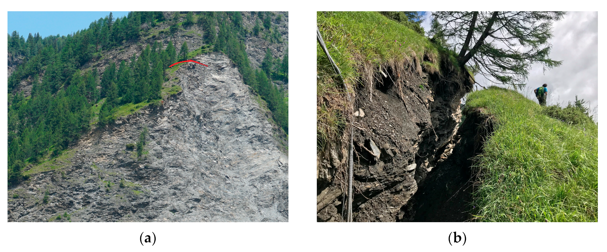
:1. Introduction
2. Geological Settings
3. Applied Known Methods and Facts
3.1. The Strength Reduction Method (SRM) in FLAC3D
3.2. Apparent and Equivalent Mohr–Coulomb Parameters
3.3. Construction of the HB Limit Equilibrium Envelope for a Given Reduction Factor F
4. The Challenge
5. Method to Overcome the Challenge: Deriving the HB Parameters Close to the Limit Equilibrium Envelope by Varying GSI and/or D
6. Stability Analysis of the Valley Flank Vals
6.1. Model Procedure
- Model 1a: Mohr–Coulomb before the rock fall event 2017;
- Model 1b: Mohr–Coulomb after the rock fall event 2017;
- Model 2a: Hoek–Brown before the rock fall event 2017; and
- Model 2b: Hoek–Brown after the rock fall event 2017.
6.2. Model 1—Mohr–Coulomb
Comparison of ‘Before’ and ‘After’ MC Model
6.3. Model 2—Hoek–Brown
6.3.1. Model 2a—‘Before’
6.3.2. Model 2b—‘After’
6.3.3. Comparison of ‘Before’ and ‘After’ HB Model
6.4. Model Calibration
- Critical success index (CSI);
- Heidke skill score (HSS);
- Distance to perfect classification (D2PC);
- Accuracy index (ACC).
6.4.1. Calibration of the MC Model ‘After’
6.4.2. Calibration of the HB Model ‘After’
6.5. Failure Prediction
7. Discussion
8. Conclusions
Author Contributions
Funding
Institutional Review Board Statement
Informed Consent Statement
Data Availability Statement
Acknowledgments
Conflicts of Interest
References
- Materialversuchsanstalt_Strass. Laborversuchsergebnisse BBT; Pöyry Infra GmbH: Strass, Austria, 2014. [Google Scholar]
- Dawson, E.M.; Roth, W.; Drescher, A. Slope stability analysis by strength reduction. Geotechnique 1999, 49, 835–840. [Google Scholar] [CrossRef]
- Thiele, O. Das Tauernfenster. In Der geologische Aufbau Österreichs; Oberhauser, R., Ed.; Springer: Wien, Austria, 1980; pp. 300–314. [Google Scholar]
- Frisch, W. Gradierte Serien am Tauernwestende—Zentralanstalt für Meteorologie und Geodynamik. Geol. Tiefbau Ostalpen 1978, 230, 23–24. [Google Scholar]
- Schmid, S.M.; Scharf, A.; Handy, M.R.; Rosenberg, C.L. The Tauern Window (Eastern Alps, Austria): A new tectonic map, with cross-sections and a tectonometamorphic synthesis. Swiss J. Geosci. 2013, 106, 1–32. [Google Scholar] [CrossRef] [Green Version]
- Frank, W.; Höck, V.; Miller, C. Metamorphic and tectonic history of the central Tauern Window. In Geodynamics of the Eastern Alps; Flügel, H.W., Faupl, P., Eds.; Deuticke: Vienna, Austria, 1987; pp. 34–54. [Google Scholar]
- Staub, R. Der Bau der Alpen. Beiträge zur Geologischen Karte der Schweiz; Francke: Bern, Switzerland, 1924. [Google Scholar]
- Fügenschuh, B.; Seward, D.; Mancktelow, N.S. Exhumation in a convergent orogen: The western Tauern Window. Terra Nova 1997, 9, 213–217. [Google Scholar] [CrossRef]
- Marinos, P.; Hoek, E. GSI—A geologically friendly tool for rock mass strength estimation. In Proceedings of the GeoEng 2000, Melbourne, Australia, 19 November 2000; pp. 1422–1446. [Google Scholar]
- Itasca. FLAC3D: Fast Lagrangian Analysis of Continua in 3D, Version 7.0; Itasca Consulting Group: Minneapolis, MN, USA, 2021. [Google Scholar]
- Li, A.J.; Merifield, R.S.; Lyamin, A.V. Stability charts for rock slopes based on the Hoek–Brown failure criterion. Int. J. Rock Mech. Min. Sci. 2007, 45, 689–700. [Google Scholar] [CrossRef]
- Hoek, E.; Carranza-Torres, C.; Corkum, B.C. Hoek-Brown criterion—2002 edition. In Proceedings of the 5th North American Rock Mechanics Symposium NARMS 2002, Toronto, ON, Canada, 7–10 July 2002; pp. 267–273. [Google Scholar]
- Balmer, G. A general analytical solution for Mohr’s envelope. Am. Soc. Test. Mater. 1952, 52, 1260–1271. [Google Scholar]
- Hammah, R.; Yacoub, T.; Corkum, B.; Curran, J.H. The Shear Strength Reduction Method for the Generalized Hoek-Brown Criterion. In Proceedings of the Alaska Rocks 2005, The 40th US Rock Mechanics Symposium USRMS, OnePetro, Anchorage, AK, USA, 25–29 June 2005. [Google Scholar]
- Mergili, M.; Fischer, J.-T.; Krenn, J.; Pudasaini, S.P. r. avaflow v1, an advanced open-source computational framework for the propagation and interaction of two-phase mass flows. Geosci. Model Dev. 2017, 10, 553–569. [Google Scholar] [CrossRef] [Green Version]
- Rocscience. RocData 5.011; Rocscience Inc.: Toronto, ON, Canada, 21 September 2014. [Google Scholar]
- Poisel, R.; Preh, A. Rock slope initial failure mechanisms and their mechanical models. Felsbau 2004, 22, 40–45. [Google Scholar]
- Preh, A.; Illeditsch (former Zapletal), M. The perfect mesh for FLAC3D to analyze the stability of rock slopes. In Proceedings of the 4th International FLAC Symposium on Numerical Modeling in Geomechanics, Madrid, Spain, 29–31 May 2006; pp. 1–5. [Google Scholar]
- Eccel, M. Comparison of the applicability of the Hoek-Brown and the Mohr-Coulomb failure criterion using the example of the Vals rock slope/Vergleich der Anwendbarkeit des Hoek-Brownschen und des Mohr-Coulombschen Bruchkriteriums am Beispiel der Felsböschung Vals. Master’s Thesis, Vienna University of Technology, Vienna, Austria, 26 November 2021. [Google Scholar]
- Hyvärinen, O. A Probabilistic Derivation of Heidke Skill Score. Am. Meteorol. Soc. Weather Forecast. 2014, 29, 177–181. [Google Scholar] [CrossRef]
- Formetta, F.; Capparelli, G.; Versace, P. Evaluating performance of simplified physically based models for shallow landslide susceptibility. Hydrol. Earth Syst. Sci. 2016, 20, 4585–4603. [Google Scholar] [CrossRef] [Green Version]
- Wyllie, D.C.; Mah, C.W. Rock Slope Engineering, Civil and Mining, 4th ed.; Taylor & Francis: New York, NY, USA, 2004. [Google Scholar]


| State | Initial (Before and After) | Limit Equilibrium | ||
|---|---|---|---|---|
| Before | After | After Best Fit | ||
| Model 1: Equivalent MC Parameters | ||||
| φ | 42 | 32.4 | 31.5 | |
| c (MPa) | 0.5 | 0.353 | 0.340 | |
| σt (MPa) | 0.026 | 0.026 | 0.026 | |
| Funstable | 1.420 | 1.473 | ||
| Model 2: Laboratory and HB Parameters | ||||
| σci (MPa) | 45.8 | 45.8 | 45.8 | 45.8 |
| Ei (MPa) | 30,000 | 30,000 | 30,000 | 30,000 |
| γ (MN/m3) | 0.02728 | 0.02728 | 0.02728 | 0.02728 |
| GSI | 34 | 34 | 34 | 34 |
| D | 0 | 0.37 | 0.37 | 0.35 |
| mi | 12 | 12 | 12 | 12 |
| mb | 1.14 | 0.6654491 | 0.6654491 | 0.6891914 |
| s | 6.53 × 10⁻⁴ | 2.329 × 10⁻⁴ | 2.329 × 10⁻⁴ | 2.480 × 10⁻⁴ |
| a | 0.52 | 0.5170641 | 0.5170641 | 0.5170641 |
| Funstable | 1.207 | 1.211 | ||
| Model 1 MC | Fstable | Funstable |
|---|---|---|
| 1a ‘Before’ | 1.418 | 1.420 |
| 1b ‘After’ | 1.470 | 1.473 |
| Model 2 HB | Fstable | Funstable |
|---|---|---|
| 2a ‘Before’ | 1.200 | 1.207 |
| 2b ‘After’ | 1.207 | 1.211 |
Publisher’s Note: MDPI stays neutral with regard to jurisdictional claims in published maps and institutional affiliations. |
© 2022 by the authors. Licensee MDPI, Basel, Switzerland. This article is an open access article distributed under the terms and conditions of the Creative Commons Attribution (CC BY) license (https://creativecommons.org/licenses/by/4.0/).
Share and Cite
Illeditsch, M.; Preh, A.; Sausgruber, J.T. Challenges Assessing Rock Slope Stability Using the Strength Reduction Method with the Hoek–Brown Criterion on the Example of Vals (Tyrol/Austria). Geosciences 2022, 12, 255. https://doi.org/10.3390/geosciences12070255
Illeditsch M, Preh A, Sausgruber JT. Challenges Assessing Rock Slope Stability Using the Strength Reduction Method with the Hoek–Brown Criterion on the Example of Vals (Tyrol/Austria). Geosciences. 2022; 12(7):255. https://doi.org/10.3390/geosciences12070255
Chicago/Turabian StyleIlleditsch, Mariella, Alexander Preh, and Johann Thomas Sausgruber. 2022. "Challenges Assessing Rock Slope Stability Using the Strength Reduction Method with the Hoek–Brown Criterion on the Example of Vals (Tyrol/Austria)" Geosciences 12, no. 7: 255. https://doi.org/10.3390/geosciences12070255