Comment

Comment on Nasir et al. The Mahout Structure in the Central Desert of Oman: A Possible Simple Impact Crater. Geosciences 2023, 13, 363

Postgraduate Program in Geology, Institute of Geosciences, University of Brasília, Campus Darcy Ribeiro, Brasília CEP 70910-900, DF, Brazil
Geosciences 2024, 14(4), 105; https://doi.org/10.3390/geosciences14040105
Submission received: 15 February 2024 / Revised: 1 April 2024 / Accepted: 3 April 2024 / Published: 18 April 2024

Abstract

:
A possible impact crater at Mahout in Oman was recently proposed by Nasir et al. (2023 [1]). They alleged that “crater” morphology, shatter cones, shock metamorphic evidence in quartz, plagioclase, and calcite, as well as initial geochemical information and geophysical data supported this proposal. Their conclusion was that “All current analyses suggest the impact origin of the Mahout structure” (p. 20 of the article). In this Comment, their evidence is critically discussed and largely refuted. It is demonstrated that the basis to consider the Mahout structure a possible impact structure is very limited and that further detailed, state-of-the-art analyses of the mesoscopic and microscopic de-formation features are required to obtain credible evidence. Beyond the discussion of the article by Nasir et al., this Comment emphasizes the general need for careful and comprehensive analysis of the geological structures that might, a priori, suggest a possible impact origin if, ultimately, a new impact structure can be successfully confirmed.

1. Introduction

Nasir et al. [1] reported a geological structure with alleged features of a simple impact crater. The elliptical structure at Mahout (Oman) was formed through an oblique impact (impact angle < 30°). They also claimed (compare item 3 of their Conclusions, page 21 of their article) the presence of an ejecta blanket with a bilateral shape, the observation of the high-pressure mineral coesite, and various shock deformation features such as planar fractures (PFs), feather features (FFs), and shatter cones. Three types of melt -rich polymict breccia supposedly occurred in the structure as well. These authors discussed in their Introduction that the identification of impact structures/craters has to be based on three possible lines of evidence: the identification of shock metamorphism, remnants of a meteoritic projectile or chemical traces thereof, and/or identification of mesoscopic to macroscopic shatter cones (see also [2,3,4,5,6,7,8]).
Nasir et al. also mentioned that the recognition of small impact craters may especially provide a challenge because of the limited volume of sufficient strongly shock-metamorphosed target rocks. Thus, gathering evidence for the presence of small impact structures obviously requires particularly careful investigation. Unfortunately, the work under discussion, according to four lines of investigation, namely field work, petrography, geochemistry, and geophysics, does not live up to the basic requirements for the identification of a (possible) impact structure, as will be discussed in the subsequent sections.
Quite regularly, potential new impact structures are reported in the international literature. This will, eventually, be tremendously helpful to further strengthen the terrestrial impact record. However, the evidence required for the positive identification of an impact structure must be obtained using rigorous research and according to the well-known principles of analysis of shock metamorphic features. The latter is obviously continuously refined. French and Koeberl (2010; [2]) published a comprehensive review of what serves to identify an impact structure and what would be insufficient. Any team attempting to confirm the presence of a potential new impact structure has to work with state-of-the-art methodology to confirm that the known recognition criteria are fulfilled.

2. Field Observations

In the following sections, the aspects of the work by Nasir et al. [1] that are problematic will be identified and then discussed.
In the “Geology of the Mahout Structure” section (p. 5), the authors already talk about an “impact crater”, which is not called for, as at this point, no evidence that in their view would permit to refer to an impact origin, has been introduced yet. As I will demonstrate below, they failed to do this anyway. Furthermore, they stated that a “sheet of melt-bearing polymict breccia” occurred in the structure’s interior. They described the occurrence of “… breccia, impact melt lapilli, and bombs” in the cover of the outer crater rim. For neither of these claims did they present any evidence, especially not for any occurrence of these latter phases. What is the evidence to allow the description of “impact melt lapilli”? Do they have melt? And if so, what is the proof for the presence of impact melt? They also referred to an “ejecta mixture to form a blanket to the north and northeast of the crater rim” and “blanket rays” without illustrating these. What is the evidence for the presence of ejecta? Where is the necessary comparative description and discussion of the debris in the proximal and distal areas around the structure?
Finally, these authors claimed that “At the crater wall, the bedrock strata are inverted and fall radially outward”. Outward dips are also indicated with dip/strike values—but only in the outermost stratigraphic layer around the structure—in their figure 3. The illustrated values would normally indicate the presence of a domal geological structure. In order to prove their claim of stratigraphic inversion, evidence of different strata orientations should have been provided for the lithologies along the inner “crater wall” and on top, in comparison to the orientations on the outer rim wall. Proof for older strata having been deposited on top of younger ones is required to confirm the overturn of strata (inverted stratigraphy).

3. Shatter Cones

Shatter cones are a most important tool for the identification of impact sites and have been used abundantly to identify bona fide impact structures. Thus, should this rock deformation phenomenon (for detailed recent treatments of this phenomenon, see [5,6], and more detail is provided in the Discussion section of this Comment; in Figure 1, a few examples of true shatter cones from confirmed impact structures are shown) be identified at Mahout, this would constitute strong evidence for the presence of an impact structure.
Nasir et al. [1] claimed that they had found “four samples showing shatter cone features and many samples showing ridges, grooves, striations, and streaks” (p. 6) in dolomite and breccia ejecta. They showed these four samples in their figure 6a,b and their Supplementary Material figure S5a,b. These images are extremely important, as they could constitute valuable support for the claim of a Mahout impact crater. However, from the imagery at hand, it is not clear whether this deformation phenomenon characteristically involving divergent striae of distinct morphometry was indeed observed, or not. This is further elaborated in the Discussion section against a summary of the characteristics/recognition criteria for shatter cones. The text by Nasir et al. does not provide further characterization of these fracture surfaces on their samples from Mahout and their associated striations, so that a detailed comparison with the reviews of shatter cone characteristics in Baratoux and Reimold (2016 [5]) and in other publications in this special issue of Meteoritics and Planetary Science is not possible.

4. Shock Metamorphic Effects

The authors [1] claimed to have shock metamorphic evidence in the form of planar microdeformations in quartz, plagioclase, and calcite, besides the presence of glass in so-called polymict breccias, and coesite had also been identified in a sample of polymict breccia. On their page 11, they also claimed that plagioclase showed planar deformation features (PDFs) and alternate twin deformation. I will discuss these claims on the basis of their imagery, which, in the absence of any further description/discussion, provides the only support for these various claims:
-
The allegation of PDFs in plagioclase remains entirely unsupported and seems to constitute an error of the authors, who probably meant to refer to PFs. Their observation of alternate twin deformation should have been illustrated/described in detail.
-
Their figure 8 allegedly shows “yellowish brown globular clasts of glasses” (p. 9) in both plane- and cross-polarized light images. The reader remains surprised and disturbed by the fact that in cross-polarized light, these “glass” clasts do not show isotropism. In figure 12, black glass is alleged to occur in black groundmass. The illustrations do not support this claim of presence of glass. And again, in figure 14, a brown glass phase is alleged that does not show optical extinction in cross-polarized light. Thus, whether any of the alleged polymict breccias are glass-bearing remains highly dubious.
-
Planar fractures (PFs), when occurring in multiple sets of (sub)planar, parallel features in quartz, are widely considered an impact-diagnostic phenomenon. According to Nasir et al. [1], PFs are present in Mahout quartz. In figure 9a, PFs should be visible, but they are not. The white lines used to indicate their presence and orientation are supposed to be 2–5 μm apart, but the spacing is more like 10 μm. It is not clear which phase (quartz?) is shown in figure 9b, but anyway, the alleged planar features remain obscure (either the thin section is of poor quality, or the grain is recrystallized). There is one set of subplanar features (fractures?) in quartz in figure 10a; however, they are partially divergent, as marked by the authors themselves with divergent white lines, and not parallel like planar fractures of shock origin should be. If there are PFs in quartz in figure 10b, they would be, in part, clearly divergent. Finally, in Supplementary Material (SM3) figure S2a, PFs are supposed to be shown in quartz as well. Unfortunately, the complex topography (?) of this grain does not allow to verify this. The same holds for the quartz grain in SM figure S3a.
-
Planar fractures in plagioclase are supposedly shown in figure 9a, where the white-line annotations again indicate divergence; the alleged fractures are invisible anyway. In figure 10b, divergent white lines mark “something” indeterminate in plagioclase, and in the lower part of this crystal, possible broad fluid inclusion trails may occur. Their figure 11a,b may show some planar features in this mineral, but whether they are fractures, cleavage, or something else is not clear. The white lines drawn onto figure 11b again seem to indicate divergence in orientation. In figure 15a,b, planar features remain invisible, and many white-line markings are divergent. In figure S1a of the SM, a set of subparallel but frequently curved features is shown. Whether this image shows two sets of planar fractures remains to be proven (by the authors). The alleged PFs in figure S1b are marked with white lines that are strongly divergent; PFs are, in this microphotograph, essentially invisible. SM3 figure S2a does not show planar fractures but rather plagioclase twinning, as does figure S2b. Whether there is partial isotropization as claimed cannot be judged on the basis of this image. If the authors want to prove this, further analytical work is required. In figure SM3 S3b, undulous extinction and PFs are supposed to be shown. The former is not a diagnostic shock effect, and the latter are invisible.
-
Planar fractures in calcite are alleged for SM3 images S4a,b. What the authors are showing are undoubtedly cleavage traces, likely parallel to twin planes. Even if there were planar fractures in this calcite grain, PFs in this mineral with excellent cleavage are not considered bona fide shock deformation.
-
Feather features (FFs) in quartz and plagioclase are mentioned in conjunction with a number of illustrations but remain elusive. It must be pointed out that FFs have never been described from feldspar minerals, and as such, are not recognized as shock (impact) evidence. Their figures 9a,b, 10a, 11a, and 13b supposedly show FFs, but they are not visible. The quality/resolution of the photomicrographs is insufficient. Further evidence for the existence of FFs in these samples is not provided either.
-
Coesite aggregates are alleged to occur in a breccia sample from Mahout. The authors claimed to have confirmed this using X-ray diffraction and provide a diffractogram that mainly displays peaks for quartz and minor phyllosilicate. Whether there are peaks for coesite must be demonstrated much better. Whether there are coesite aggregates in this sample must be verified by state-of-the-art analysis, such as Raman spectroscopy or transmission electron microscopy. As it stands now, this cited evidence must be considered with doubt.

5. Geochemistry

Nasir et al. [1] provided a series of chemical analyses of various crater facies, including what they call breccias, oxides, and glasses. A first-order observation is that the regionally occurring lithotypes have not been analyzed for comparison, so that it is entirely impossible to determine what the possible target rock chemical composition may have been. The determination of this so-called indigenous component is essential in any discussion of possible chemical enrichment of impact breccias derived from the target by a possible impactor component. To speak of “enrichment in specific elements” in Mahout crater facies is, thus, not permissible. The authors did point out quite correctly that some of the crater facies have relatively high elemental values (e.g., of Cr), but the abundances of other siderophile elements in such samples do not correspond to these selective high abundances. These observations should have been a strong indication to the authors that these geochemical data do not support an enrichment from an impactor component, i.e., an origin of Mahout by impact cratering.
The authors also pointed out that iron oxide-rich samples have high concentrations of Co and Ni without observing that these two elements generally do not occur in their samples in a correlative trend, and that high abundances of these siderophile elements in Fe-rich samples must be expected anyway (under any geochemical process). And yet, they consider, for example, that “The silica–iron breccia from the rim area shows intermediate composition between the lithic silica breccia and iron oxide samples, indicating mixing between the iron oxide rock and the lithic silica breccia, possibly during impact” (p. 15 of the article). This reference to impact is clearly unjustified. Nasir et al. proceeded with a short discussion of possible impact-induced hydrothermal activity, which, in light of the present critique of alleged evidence of impact, is not significant. However, it would have been good to discuss the geology of the environs around Mahout for a comparative discussion of the geology, facies, and possible hydrothermal mineralization at the structure and in its environs, and then the hydrothermal mineralization in the structure’s area may have become relevant indeed.

6. Geophysics

Magnetics and gravity data for the Mahout area are discussed, with the support of respective anomaly maps (their figure 22a and b, respectively). It is repeatedly stated that the elliptical shape of the structure was evident in these images: this is not so. It is also impossible to positively locate the structure on these images, which have a UTM coordinate notation, as the geological representation of their figure 3 entirely lacks geographic coordinates (and, by the way, figure 22a,b are lacking scale bars). Thus, it is also impossible to compare the geology (e.g., the extent of the alleged breccia lens) with the geophysical anomalies. One may also wonder to what extent it is possible to interpret the geophysical model in figure 23, as nothing is known about the resolution of the data. It does appear though that density may be decreasing below the structure, which is certainly an aspect that might be consistent with a damage zone below a simple impact crater. However, regarding this discussion of evidence for impact, geophysical observations may provide hints at a setting consistent with the consequences of impact, but they themselves are not of impact-diagnostic value.

7. Discussion and Conclusions

Let us assume that Mahout could represent an impact structure. What would be in favor of this suggestion? After a comprehensive critique of the alleged shock petrographic evidence offered by Nasir et al. [1], what remains is the following:
-
Allegation of stratigraphic inversion at the top of the structure’s rim: This must be fully demonstrated by further structural geological and stratigraphic analysis.
-
Presence of ejecta inside and outside of the crater: An ejecta blanket is inferred but not demonstrated (such as a mapped distribution of fragments under the consideration of the particular topography at the site and the desert environment, orientation of rock fragments, definition and orientation of ejecta rays, and in any case, melt-bearing lithologies (see below). As mentioned above, the possible difference between proximal and distal debris on the surface around the alleged crater structure must be evaluated.
-
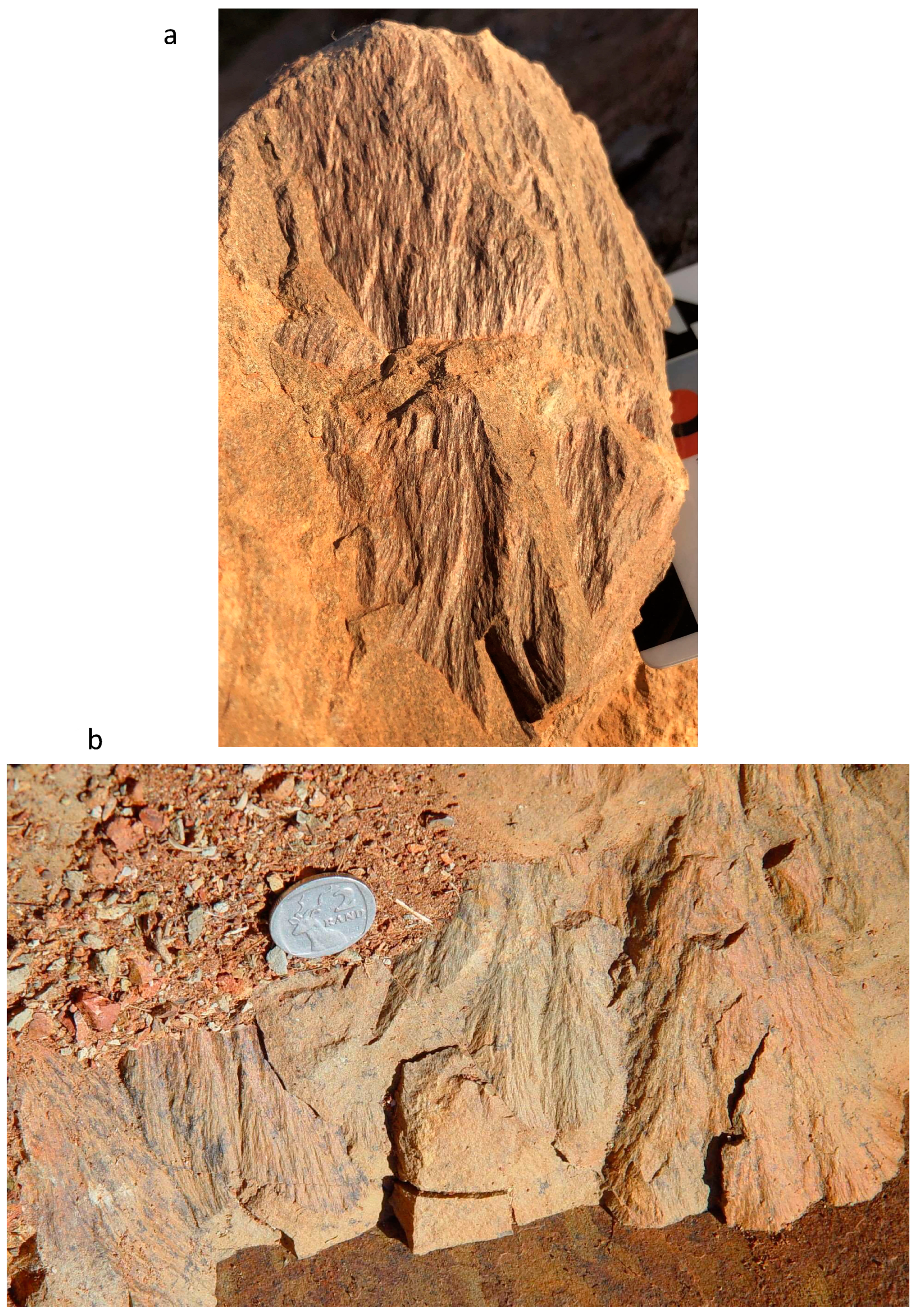
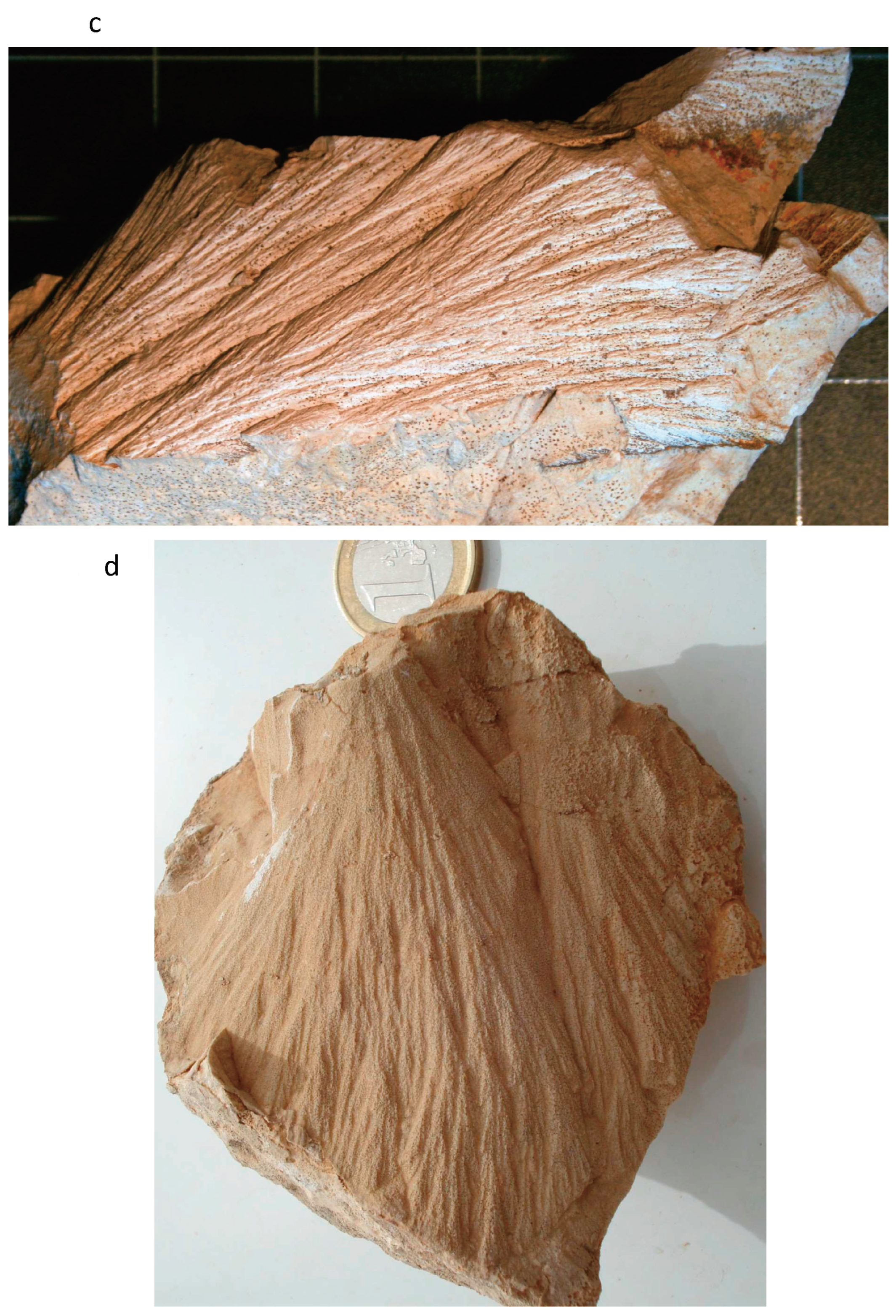
Allegation of four samples with possible shatter cones: The illustrations provided do not allow the confirmation of this claim. Thus, further work on these possibly crucial samples is required. This should also involve a petrographic analysis of the samples’ interiors, as planar fractures and planar deformation features (PDFs) have been occasionally observed inside samples with shatter cone surfaces. A detailed characterization of where these critical samples were observed and of the samples’ morphologies is mandatory. How do these samples compare against bona fide, impact-generated shatter cones (compare Figure 1)?
-
Alleged presence of “coesite aggregates”: The X-ray diffractogram provided does not allow the confirmation of this claim. Further state-of-the-art analysis using SEM and especially Raman spectroscopy, perhaps even TEM, are required to confirm the presence of this high-pressure polymorph in a sample from Mahout.
In particular, the alleged finding of shatter cones at Mahout is of importance and requires more detailed discussion. The images of Nasir et al.’s alleged shatter cones fail to provide sufficient resolution and satisfactory lighting/shadow conditions to demonstrate that the visible striations are indeed of a rounded shape (figure 6a,b) or divergent from the apex side of the sample to the base of the cone fractures (figure 6b). Additional images in S5 of the Supplementary Material (SM) show a carbonate sample that apparently has rounded striations, but the surface shown has been subjected to weathering. Both images of the alleged shatter cones in S5 of the SM do not show the divergence of striations.
In fact, shatter cones are characterized by the conical geometry of the specific fracture surface, in addition to the presence of bundles/garbens of divergent striations that may or may not bifurcate. These striations extend between an apex or apical area of the cone/partial cone and clearly diverge towards the opposite side, sometimes with well-expressed flaring of the striae in the basal section of the conical fracture surface (compare examples shown in Figure 1). Shatter cones may have sizes ranging from centimeters to several meters. They are generally best developed in fine-grained lithologies, such as limestone or pelitic rocks. Detailed microscopic and electron microscopic studies have shown that the striae alternate with groove features, and both may be, at least partially, coated by melt. Ridges are invariably rounded in contrast to other striation phenomena such as slickensides, which are characterized by angular step-like striations. Shatter cones do not represent a pure surface phenomenon but are formed by fracture systems that penetrate the affected rock volume. These fractures/joints frequently occur in multiple sets of parallel fractures that are invariably striated (multipli-striated fracture surfaces described in the relevant literature: e.g., [9]). Despite these clear recognition criteria, field situations may not always allow the straightforward determination of the presence of shatter cones, and confusion with other phenomena such as the already-mentioned slickensides, plumose fractures, ventifacts, diagenetic cone-in-cone structures, percussion features, cleavage phenomena, and man-made blast fractures from quarrying or roadwork can occur [6,10]. Finally, the imagery provided by Nasir et al. [1] lacks convincing evidence for the specific branching, bifurcation, and superposition of sub-cones generally observed on bona fide, impact-generated shatter cone surfaces.
The geochemical and geophysical observations in [1] are, as discussed above, without impact-diagnostic value. As the impact origin of the alleged Mahout structure is not demonstrated, it is premature to further address, at this point, other aspects of the authors’ Discussion section, such as ideas pertaining to their envisaged impact formation process.
The shock formation of coesite may require significant shock pressure: in a nonporous target, >20 GPa [[11], their Table 4]; in a porous target rock (e.g., sandstone with > 10% porosity), for the formation of traces of coesite, >5.5 GPa [ibid, their Table 9]; and for the significant formation of coesite, >13 GPa [ibid]. Thus, it is strange that the large number of samples analyzed by the authors did not yield bona fide shock metamorphic evidence, for example, in the form of planar deformation features (PDFs). These could form in nonporous target rocks at shock pressures above about 8 to 10 GPa, and in porous target rocks, above 15 GPa [11]. Contrary to the limited observation of PDFs in shocked porous sandstone referenced in [11], Kowitz et al. [12] observed the formation of diaplectic quartz glass from shock pressures as low as 5.5 GPa. Notably, no diaplectic quartz glass has been offered in [1] from Mahout.
Should there be extensive presence of impact-generated melt at Mahout, this would—for the case of a nonporous target—indicate shock pressures in excess of 45 GPa [11]. However, as shown by Kowitz et al. [12], in the case of porous target rocks (specifically sandstone), this would indicate a minimum shock overprint of 12.5–15 GPa (10–20% diaplectic glass/shock melt). Likely, such pressures would also result in at least some generation of planar deformation features.
Shock petrographic work is generally focused on microdeformations in the mineral quartz. This mineral occurs abundantly and is very widespread in the Earth’s upper crust. It is quite resistant against alteration as well as against metamorphism. And, as demonstrated by Stoeffler et al. [11] and the literature referenced there, quartz is a great shock barometer, as it may develop a range of different shock effects with increasing shock pressure. The formation conditions of these shock effects have been reasonably well pressure-calibrated. Kowitz et al. [12] provided a shock calibration for quartz in porous material.
Nasir et al. [1] alleged the significant formation of planar fractures in plagioclase. Shock deformation in feldspars, in general, has been investigated abundantly (see references in Stoeffler et al. [11]) for two reasons: feldspars represent the most abundant minerals in the Earth’s crust, and furthermore, plagioclase is a major rock-forming mineral in extraterrestrial rocks, too. In comparison with quartz, however, feldspars have a serious deficit as a shock barometer, namely that their crystal structures result in ample cleavage, often in multiple crystallographic orientations. Twinning of feldspar, in general, and polysynthetic twinning in plagioclase, in particular, provide a basis for fracturing along preferred orientations in the crystal structures. This kind of fracturing does, however, not require the high pressures related to shock compression, but can already be achieved by “normal” crustal-tectonic processes. Thus, particular caution is required when observing (sub)planar fractures in feldspar and equating such observations with shock deformation.
Twinning and fracturing also go hand in hand in calcite deformation, so that the claim by Nasir et al. [1] to have shock deformed calcite at Mahout is considered rather suspect and presented without any supporting evidence.
Consequently, the claim by Nasir et al. [1] that Mahout could be “a possible simple impact crater” is, at this time, not tenable. Whilst it is appreciated here that the authors refer, e.g., in their title, to a possible impact structure at Mahout, their article is misleading insofar as they persistently claim throughout the article to provide impact-diagnostic evidence. This claim is refuted in this Comment. To refer to impact, impact deformation (shatter cones, shock metamorphic effects), or impact breccia requires a priori verification of the veracity of any evidence. Further detailed work is necessary on the Mahout structure along all lines of investigation, but particularly regarding the suggested shatter cones and alleged shock deformation from Mahout. This conclusion does—at this point in time—not mean that this structure is not of possible merit for further study; on the contrary, it is encouraged to make additional efforts to better understand this structure and its formation. It is hoped that Nasir et al. will proceed with further state-of-the-art research to try to obtain the currently missing diagnostic evidence regarding the origin of the Mahout structure.
This discussion of the Mahout case may provide an example for other researchers who think or suspect that they are onto something interesting, such as a potential impact structure. First-order observations, such as a morpho-structure reminiscent of a crater shape, or a circular/elliptical geophysical anomaly, may provide intrigue but, by themselves, are not of diagnostic value. However, such observations must be followed up by detailed, dedicated forensic work. The eventual results must be presented in sufficient detail and supported by quality illustrations in order to allow one to judge and then, possibly, appreciate the value of the outcomes.
The necessity to particularly demonstrate a presence of planar deformation features (PDFs), the prime impact-diagnostic shock metamorphic effect, is obvious. The formation of PDFs is exclusively related to bona fide shock metamorphism. The demonstration of the presence of PDFs, i.e., the presence of shock metamorphism generated in the shock pressure range from ca. 8 to 15 GPa in the case of single sets of PDFs per host grain, and from ca. 15 to 35 GPa in the case of multiple sets of PDFs of different crystallographic orientations per host grain, involves that all criteria of these features, as laid out in, e.g., French and Koeberl (2010—[2]), are fulfilled. This relates to the planarity of the features (distinct straightness of their traces in a thin section), exact parallelism, thickness of the individual features (1–2 μm, whereby a TEM analysis will reveal that such features are indeed bundles of much thinner features with thicknesses in the 100 nm range), spacing (ca. 2–10 μm), and a precise crystallographic orientation along specific lattice planes. The latter requirement can only be fulfilled through a detailed universal-stage analysis, application of a spindle stage in the case where individual grains can be separated, or use of a transmission electron microscope (TEM).
Where a universal-stage or TEM and relevant experience are not available, it is recommended to seek the assistance (cooperation) of a well-reputed worker in the field of shock metamorphism. The recent literature on shock metamorphism of quartz and zircon (e.g., [3,11,12,13,14]) can lead to relevant institutions, which involve both natural history museums and academic departments. Those colleagues with shock metamorphic experience will not hesitate to assist. In the end, it is understandably attractive to participate in the discovery and confirmation of a new impact structure.
It is, furthermore, recommended here to make use of the full mineralogy provided by the rock samples from a potentially interesting structure for shock deformation investigations. Indeed, Nasir et al. did look at feldspar and calcite in addition to quartz, as discussed above, but there is a host of other minerals that could potentially evidence shock deformation. A mineral that has received particular attention by shock workers in recent years is zircon, a common accessory in all kinds of possible target rocks. Claims to have found diaplectic glass in quartz and planar deformation features in quartz and feldspar must consider that these shock deformation effects result from shock metamorphism in excess of 10–15 and up to 40 GPa. Thus, further support for this should be sought through the shock petrographic analysis of other minerals, such as zircon, monazite, sphene, apatite, and other accessories.

Funding

The author’s research at the University of Brasília was partially supported by the Brazilian Coordination for the Improvement of Higher Education Personnel (Coordenação de Aperfeiçoamento de Pessoal de Nível Superior—Brazil (CAPES)), under Finance Code 001.

Acknowledgments

I would like to thank the two anonymous reviewers for their supportive statements and valuable suggestions that allowed me to expand this Comment with further detailed discussions, especially regarding the characterization of shatter cones and planar deformation features.

Conflicts of Interest

The author does not declare any conflicts of interest.

References

  1. Nasir, S.; Economou, N.; Al Hooti, K.; Al Hosni, T.; Spratley, S.; Spratley, B. The Mahout structure in the central desert of Oman: A possible simple impact crater. Geosciences 2023, 13, 363. [Google Scholar] [CrossRef]
  2. French, B.M.; Koeberl, C. The convincing identification of terrestrial meteorite impact structures: What works, what doesn’t, and why. Earth-Sci. Rev. 2010, 98, 123–170. [Google Scholar] [CrossRef]
  3. Ferrière, L.; Morrow, J.R.; Amgaa, T.; Koeberl, C. Systematic study of universal-stage measurements of planar deformation features in shocked quartz: Implications for statistical significance and representation of results. Meteorit. Planet. Sci. 2009, 44, 925–940. [Google Scholar] [CrossRef]
  4. Reimold, W.U.; Koeberl, C. Impact structures in Africa: A review. J. Afr. Earth Sci. 2014, 93, 57–175. [Google Scholar] [CrossRef]
  5. Reimold, W.U.; Ferrière, L.; Deutsch, A.; Koeberl, C. Impact controversies: Impact recognition criteria and related issues. Meteorit. Planet. Sci. 2014, 49, 723–731. [Google Scholar] [CrossRef]
  6. Baratoux, D.; Reimold, W.U. The current state of knowledge about shatter cones: Introduction to the special issue. Meteorit. Planet. Sci. 2016, 51, 1389–1434. [Google Scholar] [CrossRef]
  7. Koeberl, C. The geochemistry and cosmochemistry of impacts. In Treatise on Geochemistry, 2nd ed.; Holland, H.D., Turekian, K.K., Eds.; Elsevier: Oxford, UK, 2014; Volume 2, pp. 73–118. [Google Scholar] [CrossRef]
  8. Kenkmann, T. The terrestrial impact crater record: A statistical analysis of morphologies, structures, ages, lithologies, and more. Meteorit. Planet. Sci. 2021, 56, 1024–1070. [Google Scholar] [CrossRef]
  9. Nicolaysen, L.O.; Reimold, W.U. Vredefort shatter cones revisited. J. Geophys. Res. 1999, 104, 4911–4930. [Google Scholar] [CrossRef]
  10. Osinski, G.R.; Ferrière, L. Shatter cones: (Mis)understood? Sci. Adv. 2016, 2, e1600616. [Google Scholar] [CrossRef] [PubMed]
  11. Stöffler, D.; Hamann, C.; Metzler, K. Shock metamorphism of planetary silicate rocks and sediments: Proposal for an updated classification system. Meteorit. Planet. Sci. 2018, 53, 5–49. [Google Scholar] [CrossRef]
  12. Kowitz, A.; Güldemeister, N.; Schmitt, R.-T.; Reimold, W.U.; Wünnemann, K.; Holzwarth, A. Revision and recalibration of existing shock classifications for quartzose rocks using low-shock pressure (2.5–20 GPa) recovery experiments and mesoscale numerical modeling. Meteorit. Planet. Sci. 2016, 51, 1741–1761. [Google Scholar] [CrossRef]
  13. Wittmann, A.; Kenkmann, T.; Schmitt, R.T.; Stöffler, D. Shock metamorphosed zircon in terrestrial impact craters. Meteorit. Planet. Sci. 2006, 41, 433–454. [Google Scholar] [CrossRef]
  14. Timms, N.E.; Erickson, T.M.; Pearce, M.A.; Cavosie, A.J.; Schmieder, M.; Tohver, E.; Reddy, S.M.; Zanetti, M.R.; Nemchin, A.A.; Wittmann, A. A pressure-temperature phase diagram for zircon at extreme conditions. Earth Sci. Rev. 2017, 165, 185–202. [Google Scholar] [CrossRef]
Figure 1. Examples of shatter cones from 4 confirmed impact structures, selected to emphasize some important characteristics of this impact-diagnostic deformation phenomenon. Shatter cones occur in shocked target rocks of the crater structure or in clasts of target rocks in impact breccia. (a) Shatter cone fractures in a sandstone clast within polymict impact breccia from the Araguainha Dome structure, Brazil. Black scale bar: 1 cm wide, so the length of this aggregate of cone fractures is about 10 cm. Note: the well-developed striations on a large number of cone features partially superpose each other. This clast contains a number of subparallel to parallel fractures, all of which have cone structures on them. Other fractures terminate the extension of cones and represent the loci where cone fractures originate from. (b) Aggregate of shatter cones along an exposure of shale within the prime shatter cone location in Booysens Shale Formation on Rooderand farm in the western collar of the Vredefort Dome, the erosional remnant of the central uplift structure of the Vredefort impact structure in South Africa. This image has been chosen as it illustrates the curvature of the cones, and the apices/apical areas (the latter where apices have broken off, but apical areas may also be related to the fracture surfaces at which shatter cones were formed). The partial superposition of cones and of garbens of striations from different cones is visible. The termination of cones against fractures of various orientations is also shown. The ZAR 2 coin has a diameter of 2.3 cm. (c) A ca. 14 cm long shatter cone sample in limestone from one of world’s best shatter cone locations, the Steinheim Basin impact structure of Southern Germany. This image was chosen, as it demonstrates the true conical character of these partial shatter cones, as well as the superposition of cones. In the lower right corner, a partial cone is developed on a fracture of a distinctly different orientation from that which hosts the main cone aggregate. (d) Aggregate of shatter cones in marl from the Waqf as Suwwan impact structure in Jordan. A EUR 1 coin, for scale, has a diameter of 2.33 cm. This image shows many cone structures, with often bifurcating striations that jointly represent a larger cone structure with a small apical area at the top. Striations of some of the cone structures diverge more strongly at the base (flaring).
Geosciences 14 00105 g001aGeosciences 14 00105 g001b
Disclaimer/Publisher’s Note: The statements, opinions and data contained in all publications are solely those of the individual author(s) and contributor(s) and not of MDPI and/or the editor(s). MDPI and/or the editor(s) disclaim responsibility for any injury to people or property resulting from any ideas, methods, instructions or products referred to in the content.

