Abstract
The potential contamination of underground drinking water (UDW) caused by CO2 leakage is a critical decision input for risk assessment and management decision making. This paper presents an overview of the potential alterations to UDW quality caused by CO2 and the relevant quality guidelines on drinking water. Furthermore, a framework and numerical simulator have been developed to (i) predict and assess the potential consequences of CO2 leakage on the quality of UDW; and (ii) assess the efficiency of groundwater remediation methods and scenarios for various UDW leakage conditions and alterations. The simulator was applied to a Canadian CO2 disposal site to assess the potential consequences of CO2 leakage on groundwater quality. The information, framework, and numerical tool presented here are useful for successful risk assessments and the management of CO2 capture and sequestration in Canadian geological formations.
1. Introduction
Human activities have altered the chemical composition of the atmosphere through emissions of greenhouse gases (GHGs), primarily carbon dioxide (CO2), methane (CH4), and nitrous oxide [1,2,3]. GHGs tend to warm the Earth’s surface by absorbing infrared radiation reflected by it. The principal anthropogenic GHG is CO2 [3].
This suggests that there is an urgent need to drastically reduce the quantity of GHGs, particularly CO2, which is released into the atmosphere, and stabilize the concentration of CO2. A potential contribution to solving this problem is the development and implementation of carbon-capture and sequestration technology (CO2 storage in deep geological formations). CO2 capture and storage (CCS) is an attractive option because it can be implemented on a large scale and also has the potential capacity for deep emission reduction [4,5,6,7].
However, before implementing CO2 storage on a large scale, its viability with regard to the long-term safety of both humans and the environment is crucial. Public safety could be jeopardized if the stored CO2 leaks into overlying sources of potable groundwater. Indeed, the interactions between the intruding CO2, water, and rocks would lower groundwater pH and thereby enhance the solubility of hazardous inorganic constituents (such as lead or arsenic) present in the aquifer rocks [8]. The release of these hazardous constituents would lead to the contamination of underground drinking water (UDW). This could impact the environment, human health, and wildlife habitats, restrict or eliminate the agricultural use of land, and pollute surface waters. It is well known that geochemical reactions that affect drinking-water quality happen in very diluted waters where minor mineral dissolution can alter water quality in such a way that environmental laws are violated [9]. This is particularly the case for trace metals where water quality standards for human consumption are high. as set by the World Health Organization (WHO, Geneva, Switzerland; e.g., arsenic: 10 µg/L, lead: 10 μg/L). Thus, an understanding of the potential alteration of groundwater quality caused by CO2 storage is crucial for successful and safe CCS. Furthermore, demonstration through modeling that CO2 leakage is unlikely to affect UDW quality would provide a strong argument in terms of obtaining a license where injection of CO2 is anticipated to take place in reservoirs or layers overlain by potable aquifers, which is the case for most onshore injection sites, including those in Canada. Furthermore, the potential contamination of UDW by CO2 leakage is a critical decision input for risk-assessment (RA) and risk-management (RM) decision making. RA and RM decision making fail if assessment of the potential consequences of CO2 leakage on UDW is lacking, or not considered.
Major research efforts are being made around the world to develop appropriate RA and RM frameworks and guidelines, as well as to establish the best practice procedures for CCS. For example, the National Risk Assessment Partnership (NRAP), which includes five U.S. national labs executing collaborative research for DOE-Fossil Energy’s Carbon Sequestration Program, has been developing defensible, integrated science-based methodology and a platform for quantifying risk at many types of CO2 storage sites to guide decision making and risk management with respect to the long-term storage of CO2 [10]. The assessment and prediction of potential impacts of CO2 storage on groundwater quality and systems is one of the key research tasks within NRAP (e.g., References [11,12,13]). In Canada, a relatively similar program (Carbon Management Canada, CMC, Calgary, AB, Canada) has been in place to support collaborative research among Canadian researchers on CCS. For example, the primary objective of one of the projects supported by CMC is, in a transdisciplinary collaboration, to develop a tailored-for-Canada framework for CCS risk assessment and management, based on best practices being developed around the world, as well as on the Canadian experience to date. The paper presents results obtained from this project with regards to potential groundwater contamination by CO2 storage.
The objectives of the present paper are:
- -
- to present a framework and a numerical simulator that have been developed at the University of Ottawa to predict and assess the potential consequences of CO2 leakage on the quality of UDW;
- -
- to provide an overview of the potential alterations in UDW quality caused by CO2 and drinking-water quality guidelines (which are relevant for groundwater contamination caused by CO2) that exist in Canada and other countries; and
- -
- to present an example of the application of the developed simulator to assess the consequences of CO2 leakage on the quality of groundwater located in a Canadian CO2 storage site.
2. Developed Framework
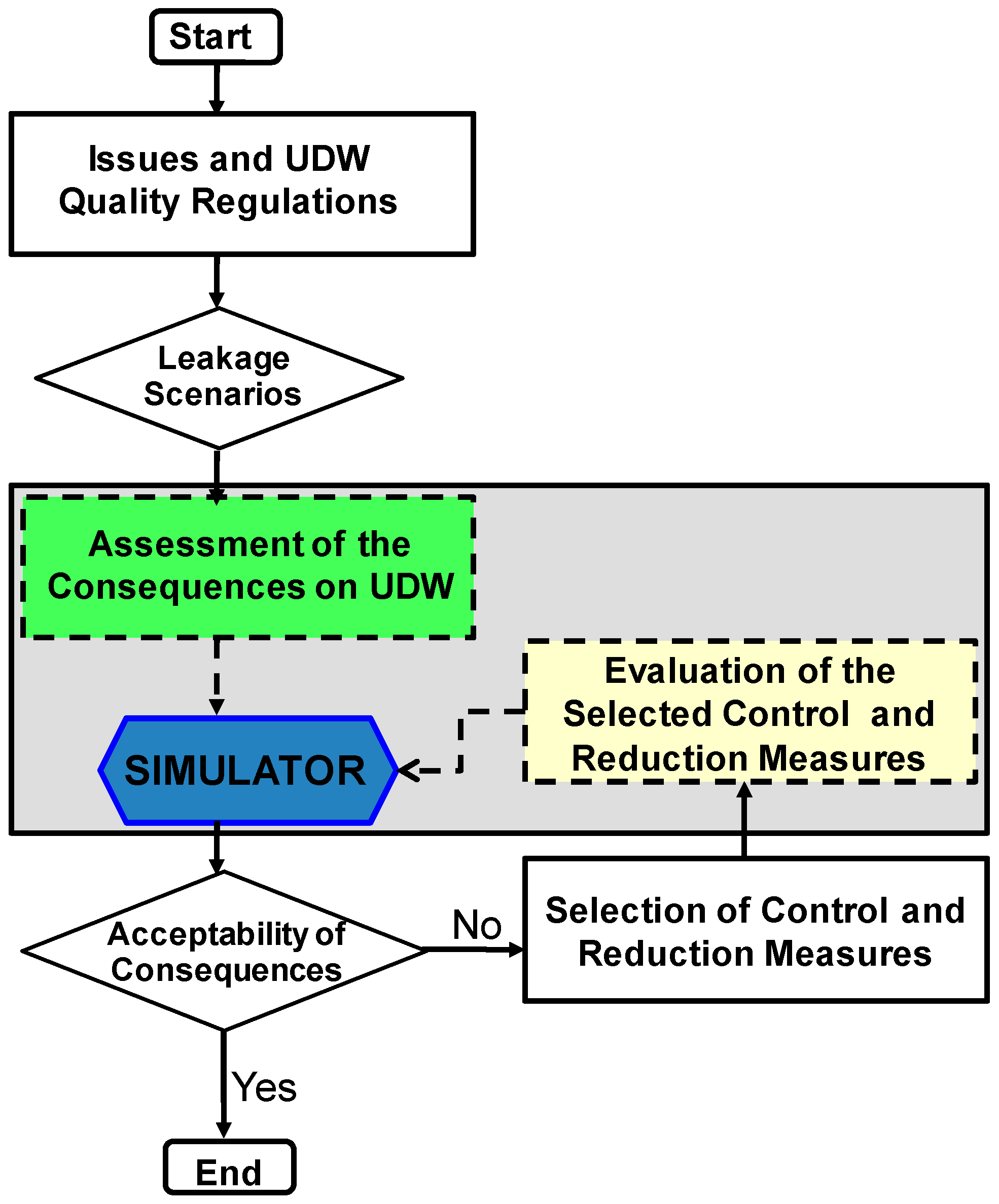
Figure 1 presents the key building blocks of the framework developed to evaluate the consequences of CO2 leakage on the quality of UDW and to assess the efficiency of groundwater remediation methods and scenarios. The framework involves:
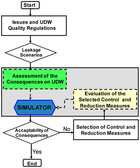
Figure 1.
Framework to predict and to assess the potential consequences of CO2 leakage on the quality of underground drinking water (UDW) as well as assess the efficiency of groundwater mitigation methods and scenarios.
- (i)
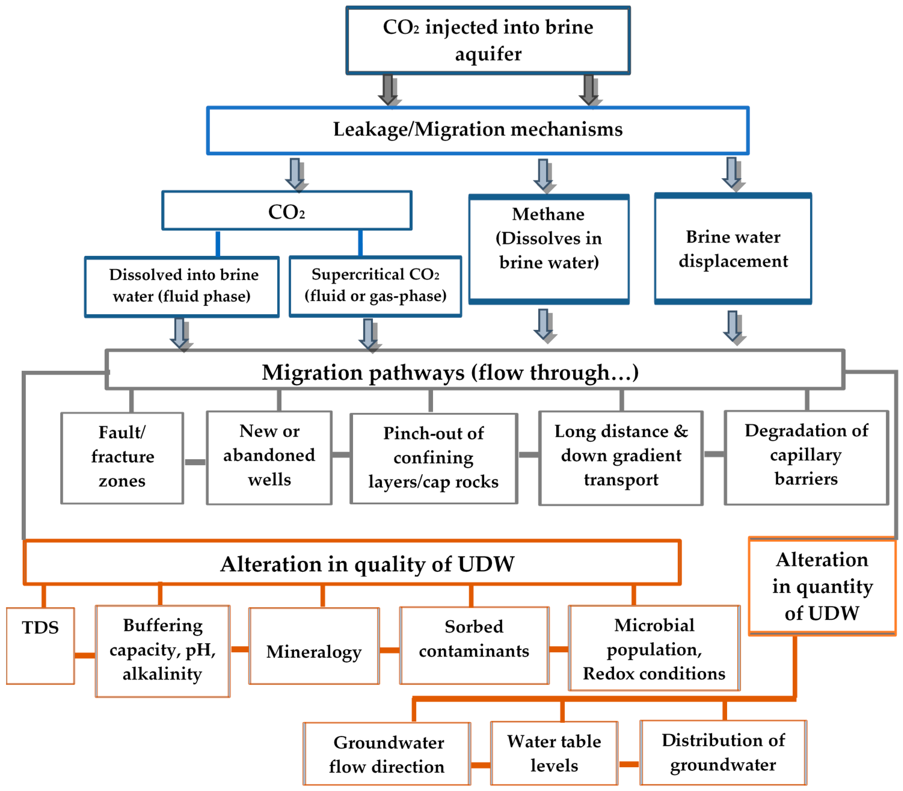
- an understanding and the identification of all potential mechanisms and processes of UDW quality alteration caused by CO2 disposal and/or leakage. Figure 2 depicts the potential mechanisms and processes of UDW alteration by unanticipated leakage and/or migration of CO2;
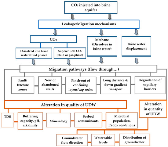 Figure 2. Mechanisms of alteration in UDW caused by CO2.
 - (ii)
- the identification of UDW guidelines or standards (which describe the quality parameters set for drinking water) that apply to the CO2 injection site or region. Table 1 shows current worldwide guidelines for drinking water quality in terms of the chemical parameters (relevant to CCS), and Table 2 shows the Canadian guidelines for the main chemical and physical parameters. These guidelines establish the maximum acceptable concentrations (MACs) of various chemical substances in drinking water. The WHO guidelines are used as the basis for regulation and the setting of standards in many countries.
 Table 1. Maximum acceptable concentrations (MACs) of various chemical parameters reported by the World Health Organization (WHO), European Union (EU), Environmental Protection Agency (EPA), and Australian Government National Health and Medical Research Council (NHMRC).
 Table 2. Summary of MACs of various chemical and physical parameters reported in Canadian water quality guidelines *.
 - (iii)
- the identification and development of all potential CO2 leakage scenarios by using an appropriate modeling tool and approach. Models that apply numerical, analytical, and semianalytical solution methods have been successfully used to simulate the injection of CO2 into subsurface formations, the reactive transport of CO2 and potential leakage scenarios (e.g., References [14,15,16,17,18,19,20,21,22,23,24,25,26,27,28,29,30,31,32]);
- (iv)
- the modeling and prediction of the impact of leaked CO2 on the quality of UDW for each leakage scenario previously identified by using a thermo-hydro-mechanical-chemical (THMC) simulator developed in this study (Section 3). This modeling allows evaluating the evolution of the quality or chemical composition and characteristics of the UDW in response to the intrusion of CO2;
- (v)
- (vi)
- a selection of appropriate techniques for groundwater contamination mitigation (e.g., Reference [33]) if the changes in the UDW quality induced by CO2 intrusion are judged as inacceptable;
- (vii)
- the modeling and prediction of the impact of selected mitigation techniques on the improvement in UDW quality by using the THMC simulator. The predicted chemical parameters of the remediated groundwater are then compared with those set by the selected drinking-water quality guidelines to evaluate its acceptability.
3. THMC Tool for Modeling Consequences of CO2 Leakage on UDW Quality
3.1. Introduction
The migration of leaking CO2 into groundwater systems and its interactions with aquifers, which causes potable aquifer contamination as a consequence of the leakage, involves complex thermal (T), hydraulic (H), mechanical (M), and chemical (C) couplings (e.g., Reference [34,35]). Therefore, an analysis of the consequences of this migration and related interactions requires a coupled THMC numerical tool.
In this study, a new numerical tool (TOUGHREACT-FLAC3DDM) for the coupled thermo-hydro-mechanical-damage-chemical analysis of CO2 migration and CO2–rock–water interactions has been developed. The tool is established based on the extension of TOUGH-FLAC [15]. Compared to the original scheme of Reference [15], the developed tool expands the area of applications, i.e., geochemical reactions as well as mechanical damage, and their coupled influences can be handled well by the new tool. With this new tool, not only can the injection-induced ground heave and deformation be simulated (as evidenced by Reference [15]), but it can also help study the complex geochemistry evolution happening underground. Coupling geochemistry with a THM simulator is a known trend of efforts in the numerical simulation field. It enables tremendous potential in the study and assessment of various key geoscience projects, for example, the deep geological repository for nuclear wastes, greenhouse gas, and geothermal exploration. One of the typical and successful application is in CCS projects as demonstrated in this study.
First, the T, H, and fluid–rock chemical (C) interaction capabilities of TOUGHREACT, a well-established numerical code, are coupled with the strong geomechanical (M) modeling capabilities of a finite volume formulation, FLAC3D. Then, an elastoplastic damage model is developed and implemented into FLAC3D. This results in the development of the TOUGHREACT-FLAC3DDM simulator, with the capability of modeling CO2 migration in geological media and the associated fluid–rock interactions by taking into consideration the coupled thermal, hydraulic, geochemical, and mechanical-damage processes [36].
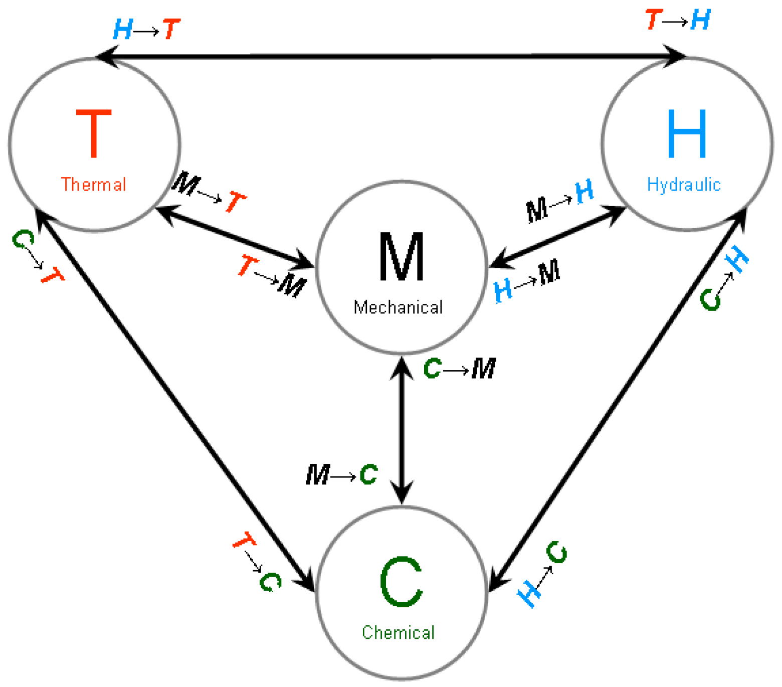
The key processes and their couplings considered by the simulator are shown in Figure 3. Some typical important multiphysics interactions are: M–H: permeability increases induced by excess stress or mechanical damage; H–M: pore collapse induced by fluid drainage and effective stress change induced by pore-pressure modifications; H–C: solute transport due to advection; H–T: thermal transport process due to advection flow; T–H: permeability changes induced by heat gradient; T–C: rate of chemical reaction changes induced by temperature changes; C–M: chemically induced porosity changes; C–H: chemically induced permeability changes. It is noteworthy that the proposed THMC numerical simulator has several novelty aspects: (1) a new mechanical constitutive model was developed and implemented in the simulator; (2) the porosity variation induced by chemical reactions (related to permeability inherently in TOUGHREACT) was further incorporated into the mechanical constitutive model in the simulator; (3) H–M coupling involving re-equilibration of pore pressure and effective stress, which is fundamental to the geomechanical assessment of well stability and groundwater flow, is taken into account by the simulator.
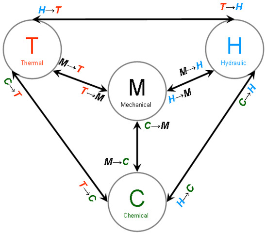
Figure 3.
Conceptual model of thermo-hydro-mechanical-chemical (THMC)-coupled processes by the developed simulator.
The developed numerical tool has been validated and tested against experimental data of CO2 or gas-injection tests on sedimentary host rocks [36,37]. The simulator structure and couplings, a description of the mathematical statements, and the governing equations of the THMC tool and examples of the validation results are presented in the following paragraphs.
3.2. Simulator Structure and Couplings
Two numerical codes, FLAC3D (designed for mechanical (M) analysis) and TOUGHREACT (THC code), have been coupled to act as a robust THMC-coupled simulator for assessment purposes to investigate potential groundwater contamination in response to CO2 leakage.
FLAC3D is a robust finite-difference program for mechanics computation, and especially professional and convenient in light of its capability to simulate the behavior of various geomaterials that undergo plastic flow when deviatoric stress yielding has been reached [38]. Specific numerical algorithms, e.g., the Lagrangian calculation scheme and the mixed-discretization zoning technique, are used to ensure accurate plastic-flow modeling. FLAC3D can handle any constitutive model with no adjustment to the solution algorithm, and is most effective when applied to nonlinear or large strain problems [38].
FLAC3D is compatible with built-in programming, thus providing a convenient interface for users to define new constitutive models. In this study, an elastoplastic damage model was developed and scripted into a dynamic link library (DLL) compatible to FLAC3D to form a new FLAC3DDM module.
TOUGHREACT, which is based on the TOUGH code, considers THC and permeability–porosity couplings as well as geochemical reactions, and multiphase solute transport that result from adsorption, interphase exchange, mineral dissolution, and precipitation. A sequential iteration approach is used by first running the solution of the multiphase flow equations, and then by using the fluid velocities and phase saturations for chemical-transport simulation. Chemical transport is solved on a component-by-component basis [39]. TOUGHREACT has proven to be efficient and reliable in the modeling of the time-dependent transport of nonisothermal multiphase/unsaturated flow and reactive transportation of chemical species in porous media.
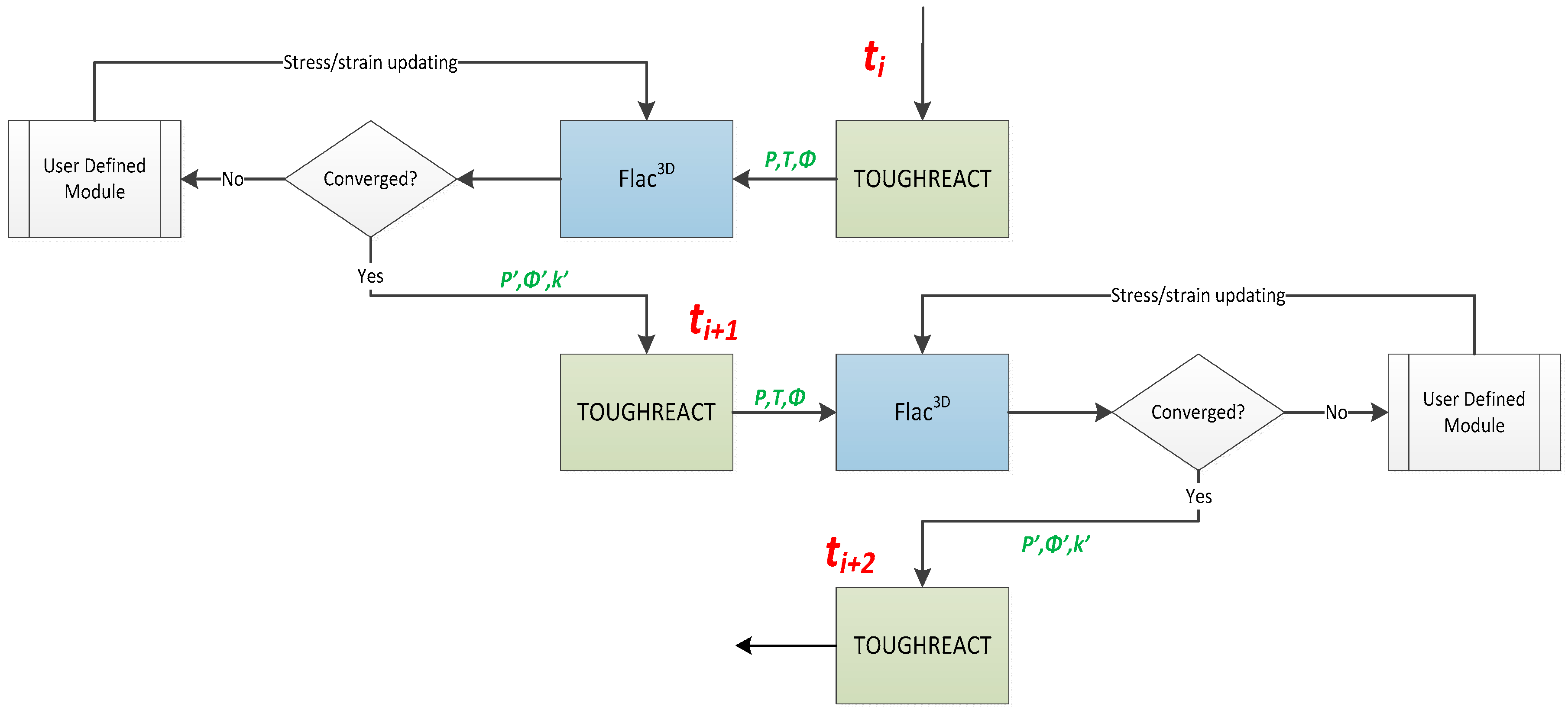
Via a series of scripted programs that were developed with the C++ and FISH languages, the primary variables, e.g., pore pressure, temperature, and porosity, were exchanged between FLAC3DDM and TOUGHREACT while meshing of the Finite Element Model (FEM) models for the both programs were kept consistent and compatible with each other. Figure 4 shows the schematic diagram of this coupling process. As variables are applied into grids in FLAC3D instead of elements as in TOUGHREACT, data interpolation was carried out when introducing these data from the simulation results of TOUGHREACT. On the other hand, the FLAC3D can output results that are represented at the elemental centers, and hence no interpolation is necessary to transfer data into the input files for TOUGHREACT. The coupling was achieved by a sequential iterative approach that can largely save memory and computation requirements.
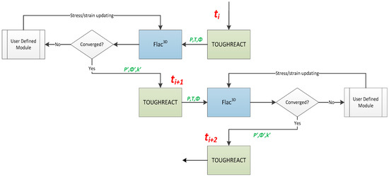
Figure 4.
Schematic diagram of algorithmic and data exchange between FLAC3DDM and TOUGHREACT.
3.3. Description of the THMC Model
A brief description of the THMC model is presented here. The THC component of the formulation adopted here is based on the THC formulation proposed in TOUGHREACT [40,41]. THC formulation is defined by a set of governing equations, constitutive equations, and equilibrium restrictions. The M component is based on the formulation proposed in Reference [38] with the extension of the elastoplastic mechanical constitutive model to an elastoplastic damage model.
3.3.1. Governing Equations and Constitutive Functions for the THC Model
The key governing equations for multiphase fluid and heat flow and chemical transport have identical structure and are derived from the principle of mass (or energy) conservation. These equations are summarized below. The main processes considered include: (1) fluid flow in both liquid and gas phases happening under pressure, viscous, and gravity forces; (2) interactions between flowing phases are represented by characteristic curves (relative permeability and capillary pressure); (3) heat flow occurring by conduction, convection, and diffusion. The governing equations were complemented with constitutive local relationships that express all parameters as functions of fundamental thermophysical and chemical variables [10,41]. The constitutive functions adopted in this study are given in References [36,37,40,41,42]. The governing equations for chemical equilibrium are given in Reference [40].
The mass conservation equation is given as [40]:
where M is mass accumulation, F is relative mass flux, q is the source/sink, and superscript k indicates the phase state (gas and liquid), heat or chemical species.
The mass accumulations of gas and liquid are in the form of:
where S is saturation, ρ is dry density, X is the mass fraction between the liquid and gas phases, and Φ is porosity.
Mass flux is expressed as follows:
The source and sink item is given as:
The mass accumulation of chemicals is written as:
where C is the chemical concentration in the liquid (Cj) and gas phases (Ck), respectively.
For chemical species in aqueous and gas phases, the mass flux is a function of fluid flow and the effective diffusion coefficient,
where subscript k is the chemical component in the gas phase, j is the chemical component in the aqueous phase, De is the effective diffusion coefficient, v is the fluid velocity, superscript l is the liquid phase, and g is the gas phase, respectively.
The source and sink item for the chemical component in the aqueous phase includes:
However, only a species in the gas phase is considered in the source and sink item for gas,
Heat balance and dissipation equations are given as:
where U is the internal energy (U = C*T, C is specific heat), h is specific enthalpy, λ is the heat-conductivity constant, T is the temperature, and superscript h is heat.
The relationship between the amount of solid precipitation and the pore space available to the fluid phases was also considered. The matrix permeability changes were calculated from changes in porosity by using permeability ratios calculated from the Carman–Kozeny relation, and ignoring changes in grain size, tortuosity, and specific surface area, as follows [40]:
where Φ is the updated porosity, and Φ0 is the original porosity before accounting for the precipitation or dissolution effects on porosity change. Gas permeability is directly dependent on porosity and relative saturation in such a form:
where Sl is the liquid-phase saturation and Sgr is the irreducible saturation for the gas phase.
A stress-related relationship for the permeability of rocks was used for easy handling of data exchange, i.e., matrix permeability between FLAC3DDM and TOUGHREACT [43]. The matrix permeability variation with respect to the mechanical coupling effect was computed by updating porosity change in the input file for TOUGHREACT. FLAC3DDM not only outputs the stress state for data exchange with TOUGHREACT, but also provides information about the volumetric strain increment (), based on which the porosity can be calculated:
where Φ is the updated porosity and Φ0 is the original porosity before mechanical coupling. The change in the porosity computed from the mechanical equilibration in FLAC3DDM is used to estimate changes in permeability by means of empirical equations. Both mechanical damage and compression could be accounted as discussed below. More details on the THC model are given in Xu and References [36,37,40,41,42].
3.3.2. Governing Equations and Constitutive Functions in FLAC3DDM
FLAC3D solves the following equation of motion [38],
where is the stress, ρ is the density of the matrix material, b is the body force, and v is motion.
The stress increment is given as:
where H is the stiffness matrix and is the strain rate. The later is governed by:
where tr means the transpose of a tensor.
For EP theory, a strength criterion must be imposed to identify the necessary conditions for the initialization of the plastic flow. The well-known Mohr–Coulomb model can be written in the following form:
where , , , J2 is second deviatoric stress invariant, I1 is the first stress invariant, C is cohesion, θ is the Lode angle, and Φ is the internal frictional angle.
The total strain increment consists of elastic and plastic strains as following:
The elastic strain reads:
where Cijkl is the compliance tensor that is representative of the elasticity.
Using associative flow rule, the strength criterion (F, Mohr–Coulomb theory in this study) can be treated as the yield function. In this regard, the plastic strain rate takes this form:
where λ is the consistency parameter that can be determined by classical elastoplastic theory with appropriate rearrangement of the differentiated form of the yield function.
FLAC3D allows users to extend the mechanical modeling database by defining new constitutive models. A user-defined model can be incorporated into FLAC3D by using the C++ dynamic link library (DLL) file. The original source code for the Mohr–Coulomb model was modified to account for mechanical damage by using continuum damage mechanics [44,45,46]. The elastic–plastic Mohr–Coulomb model was supplemented with the damage concept with respect to its influence on the elastic-modulus and shear-strength criteria.
In this case, the tool’s elastoplastic damageable (EPD) model enabled us to model the plastic strain-induced damage and the impact on permeability change. Permeability was updated by the plastic strain in an exponential manner in terms of a damage factor that was defined as a parabolic function of the plastic strain.
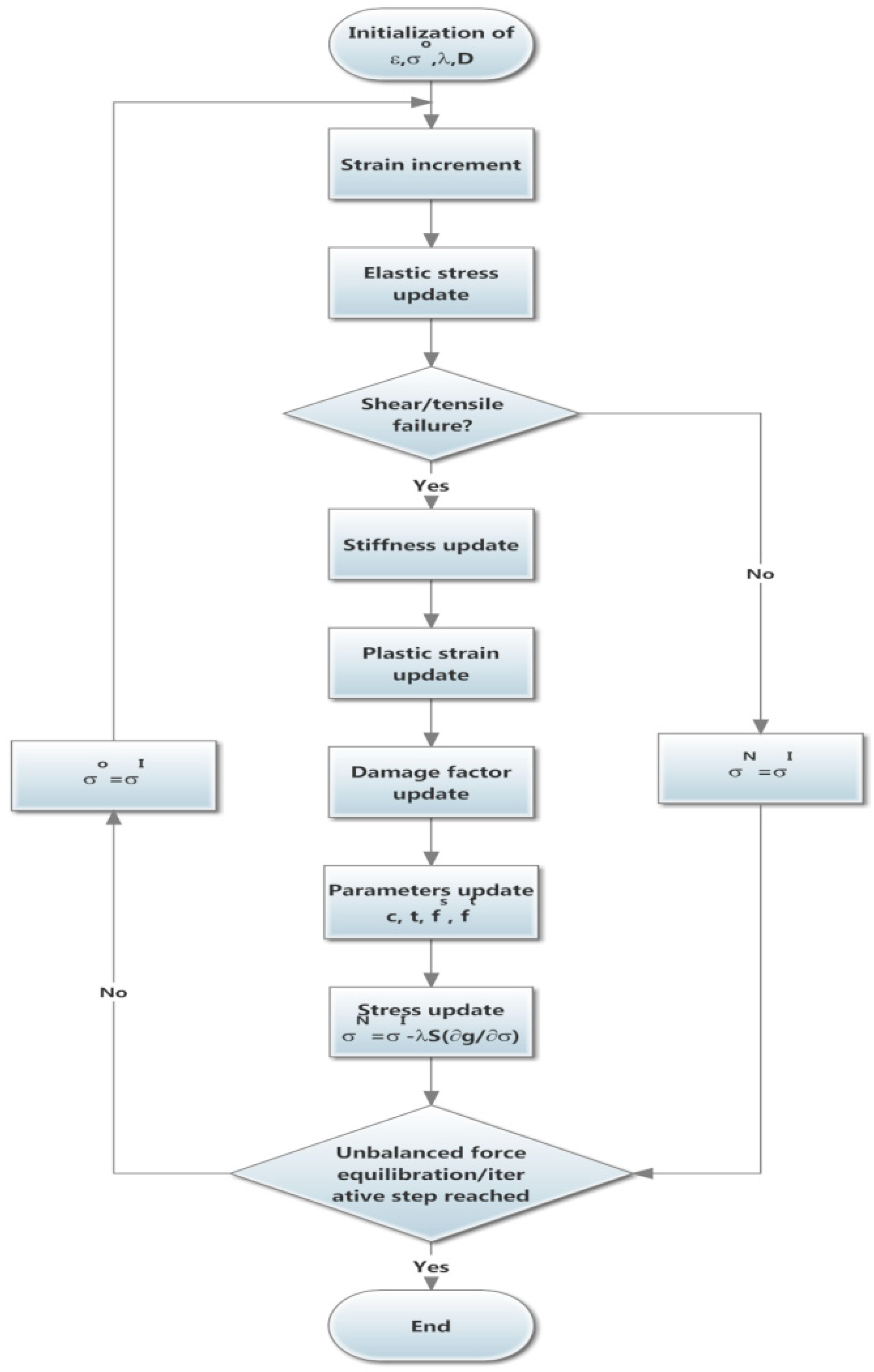
As plastic strain is required for the calculation of the damage coefficient, strain correction is supplemented from the original code. The compiled DLL file can be loaded into FlAC3D by the Fish command. Figure 5 depicts the schematic diagram for the numerical implementation of this EPD model into FLAC3D.
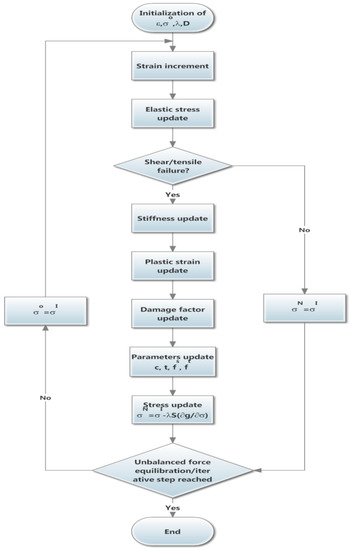
Figure 5.
Computational scheme for numerical implementation of the EPD model into FLAC3D.
In this study, an exponential evolution law is adopted [15]:
where D is damage factor, κ’ is the model constant, 1 < κ’ < 3, kD is the permeability related to the damaged material, and k0 is the permeability of the intact sample under a certain confining stress. With THMC coupling in mind, the parameter k0 in Equation (26) is equivalent to the updated permeability after porosity updating due to chemical precipitation/dissolution.
3.4. Simulator Validation
The developed modeling tool is based on two established commercial codes (TOUGHREACT, FLAC3D) that have been extensively scrutinized and successfully validated by the research community for over 15 years. Furthermore, TOUGHREACT has been successfully tested and used in many CO2 storage problems by numerous investigators from around the world. FLAC3D has been successfully applied to a wide range of problems related to geomechanical processes in geological media. Moreover, each code (FLAC3D, TOUGHREACT) is “qualified” for regulated programs, such as the Canadian and U.S. nuclear-waste program. In this study, additional validation examples of the developed TOUGHREACT–FLAC3DDM tool have been performed. The capabilities of the THMC tool to simulate CO2 migration and CO2–rock–water interactions with the associated consequences on UDW have been tested against well-controlled laboratory and field-experiment CO2 or gas-injection tests.
Validation was carried out in a trial-and-error approach. The conceptual model was first developed based on the experiment. Appropriate boundary and initial conditions were kept consistent to the test conditions. Material properties were obtained from corresponding reports and were assigned in the model. Critical parameters were identified and varied in a range for respectively running simulations until the monitored key parameters were comparable against the test data. Only the best results are presented here. The validation considers the geochemical reactions and permeability evolution laws. The validation results showed good agreement between the experimental and predicted results. Some typical examples of the validation and simulation results are presented below. Additional examples of the validation results were published elsewhere [36,37].
3.4.1. First Validation Example
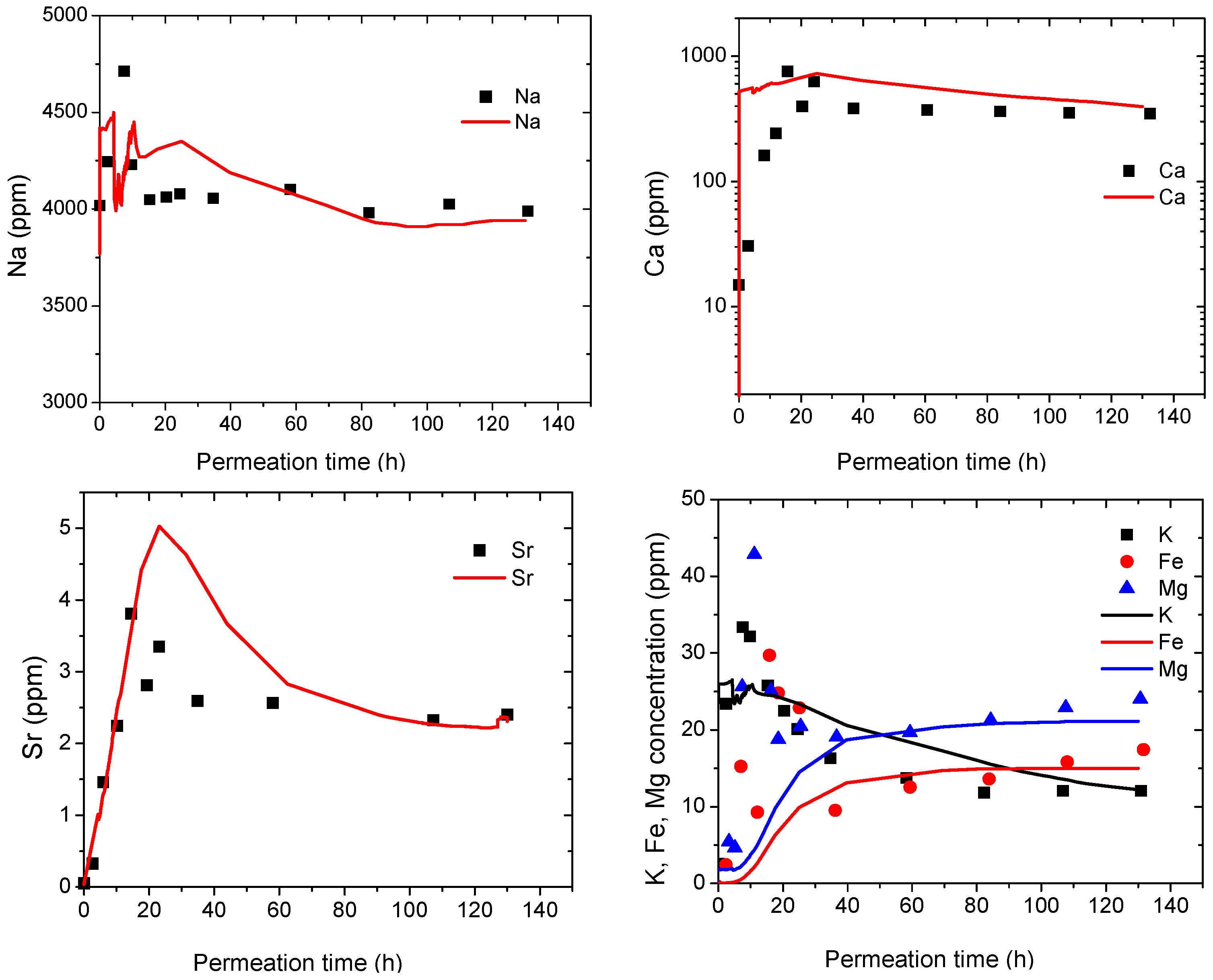
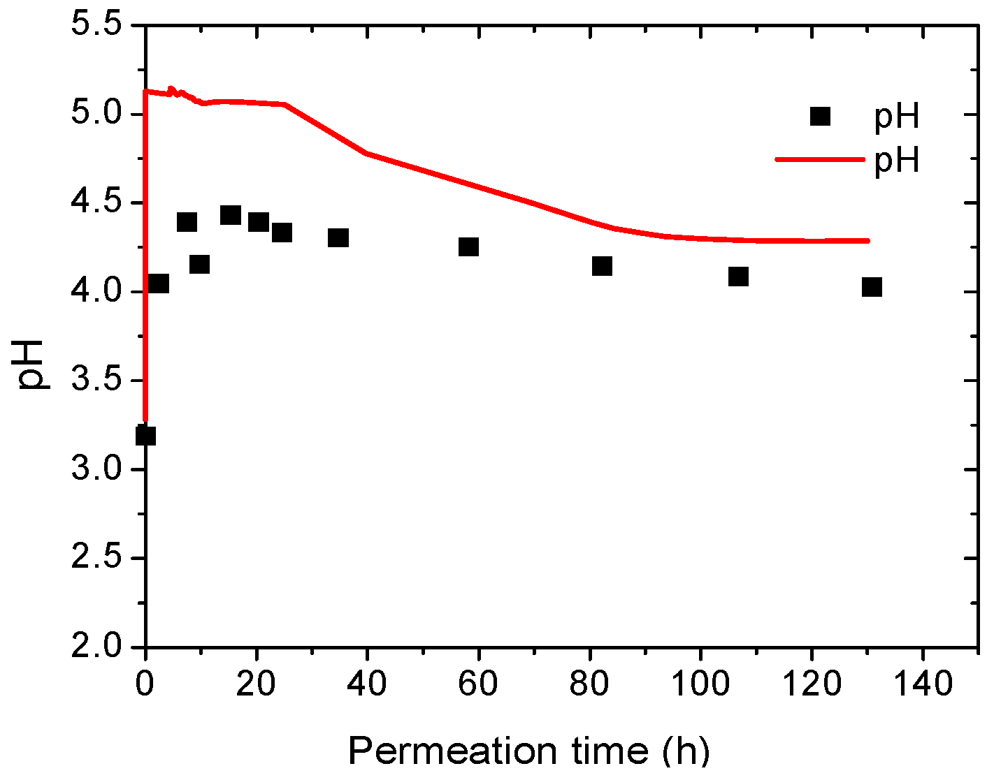
The first validation example consists of simulating a laboratory test performed by Reference [41]. These authors reported a detailed experimental study on CO2 permeation through sandstone sampled from an oil field. The rock sample was permeated with a CO2 saturated brine solution under a confining pressure of 24 MPa and temperature of 100 °C. Permeation velocity was maintained at 2.5 mL/min and sustained for 130 h. Chemical species in the leachate and mineral compositions in the porous media were analyzed, along with discussions on the permeability-reduction mechanism. The experimental work was numerically simulated by using the developed simulator with the appropriate initial and boundary conditions. Figure 6 shows a comparison example of the test data with the simulated results for the evolution of various chemical species in the leachate. It can be seen that most of the primary chemical species fit with good agreement. It is noteworthy that the simulated Ca concentration and pH are, on average, larger than the experimental results. This could be related to the assumption that calcite exists as an equilibrium mineral without taking into consideration the reaction kinetics. The current version of TOUGHREACT only allows equilibrium calculation for calcite–CO2 reactions in view of their comparatively high reaction rate (1000 times that of albite) and the large time scale. In addition, the solution pH greatly relies on the hydration reactions of surface functional groups of a variety of minerals. A better prediction of pH requires more detailed information about the surface properties, aqueous species, concentrations, and equilibration constants. Regardless of these limitations, the current simulation provides an appropriate approximation of the chemical species, and generally reflects the chemical reactions.
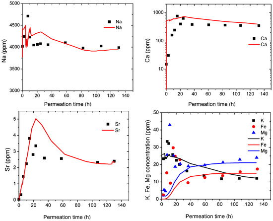
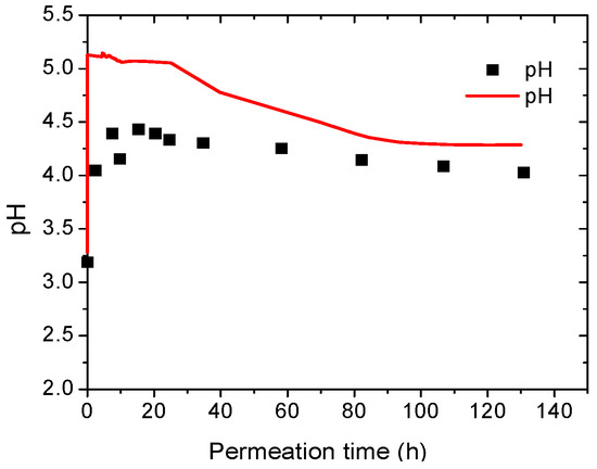
Figure 6.
Variations in chemical concentration and solution pH of leachate with permeation time (scatter is test data and curve is simulated results; simulated curve considers effects of cation exchange).
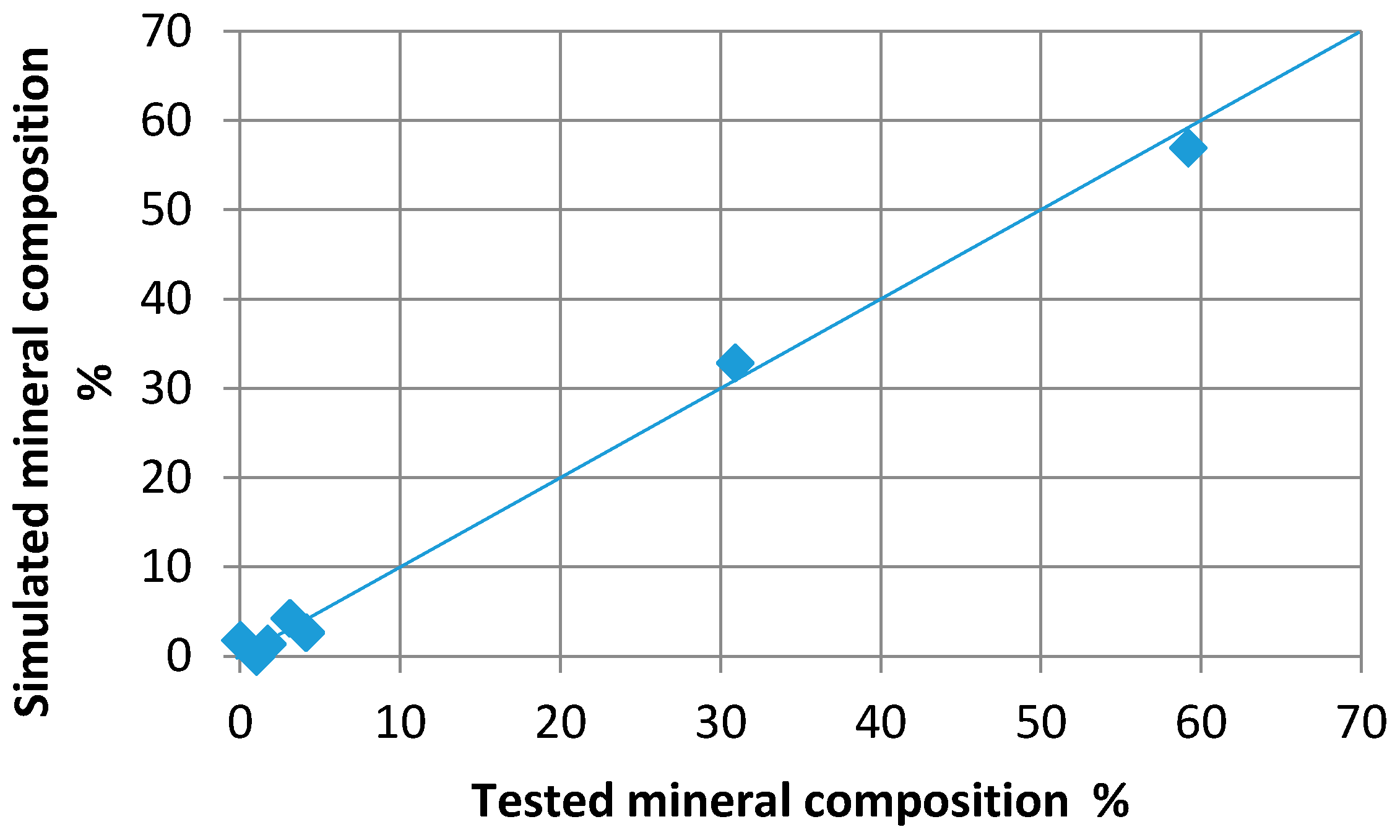
Moreover, the predicted volume fractions (%) of the different minerals (albite, calcite, celestine, illite, kaolinite, k-feldspar, quartz, and smectite) present in the sandstone were compared with the experimentally obtained data. Figure 7 shows a comparison of the simulated mineral composition with the test data. We can observe relatively good agreement between the experimental data and the predicted values.
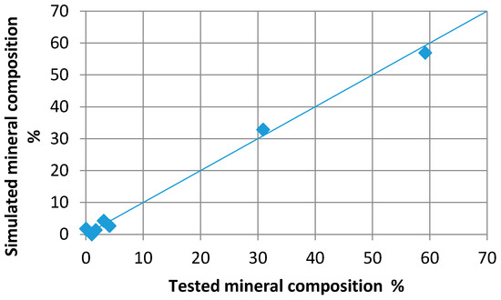
Figure 7.
Comparison of the predicted and experimentally determined volume fraction of the minerals present in sandstone.
3.4.2. Second Validation Example
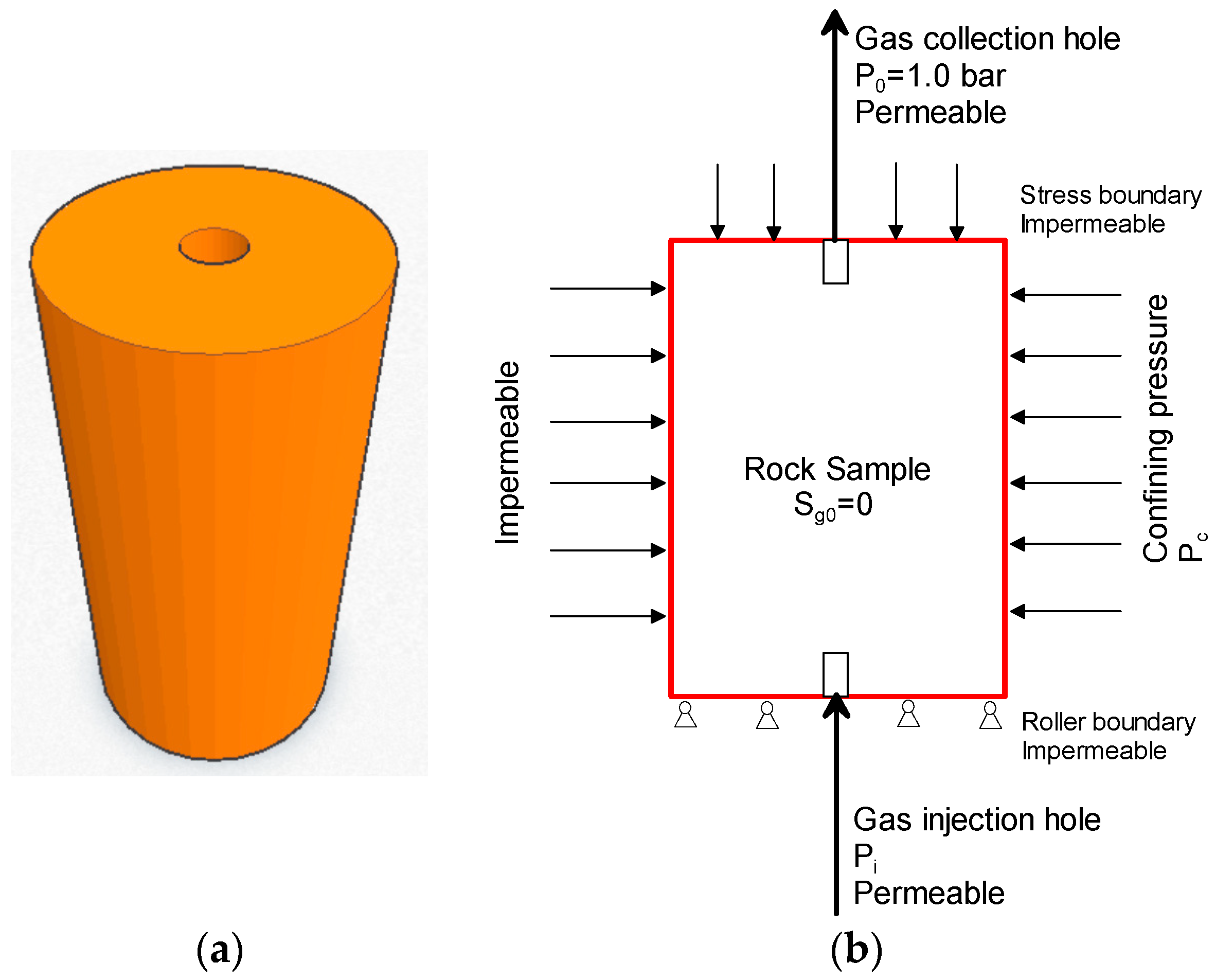
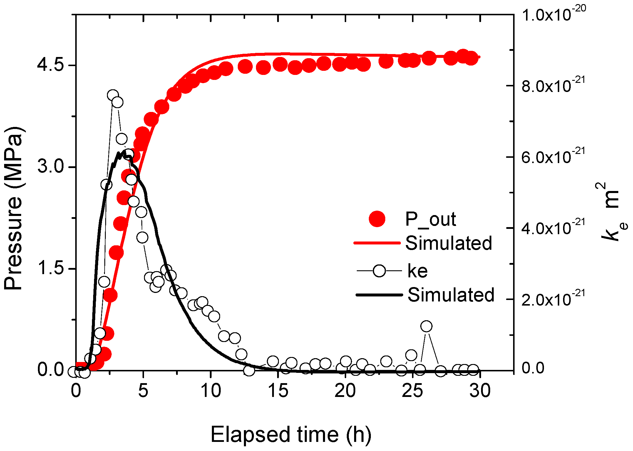
The second validation example deals with the simulation of a series of gas-breakout experiments carried out by Reference [47] to study the sealing efficiency of various types of intermediate-to-low permeable sedimentary rocks. This is a typical hydraulic–mechanical coupling problem. The test sample and relative boundary conditions are shown in Figure 8. To verify the prediction ability of the developed tool, the authors simulated a typical test on the permeation of highly pressurized CO2 through a clay stone. The cell sample was sized as 2.0 cm × 2.85 cm (L × D) and presaturated with water at 50 °C before being subjected to gas permeation. The outlet was sealed to allow the accumulation of permeated gas. The experimental procedure is explained in detail in Reference [47]. The confining pressure (also the initial stress) was maintained to at least 300 bar to ensure a leak-tight seal around the sample plugs.
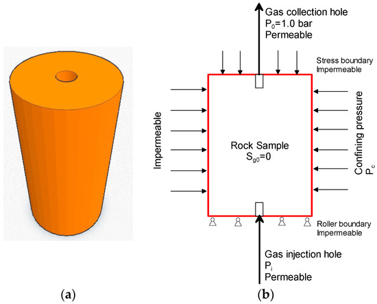
Figure 8.
Test sample (a) 3D view and (b) cross-section with boundary conditions.
Figure 9 shows a comparison of the results from the developed simulator and the results obtained by Reference [47] with respect to the evolution of the gas pressure and the effective permeability for CO2 (ke). The results show good agreement between the experimental and modeling results.
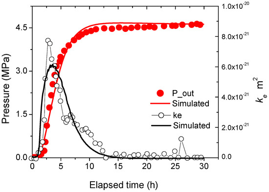
Figure 9.
Comparison of test data and simulated curve with respect to the evolution of gas pressure and effective permeability for CO2 (ke) (source: Reference [47]).
3.4.3. Third Validation Example
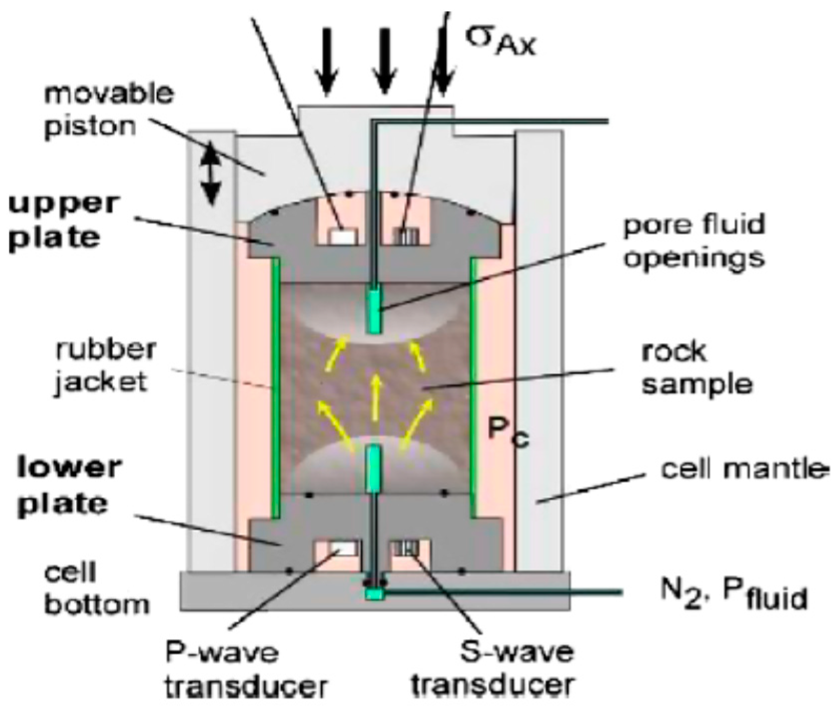
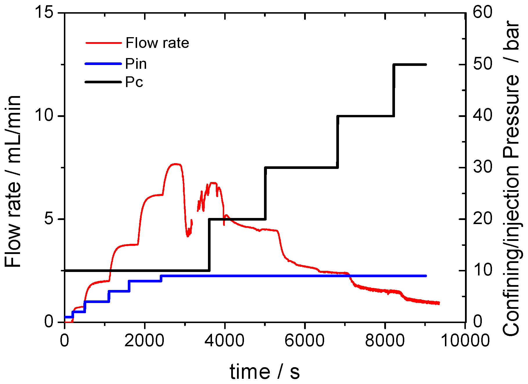
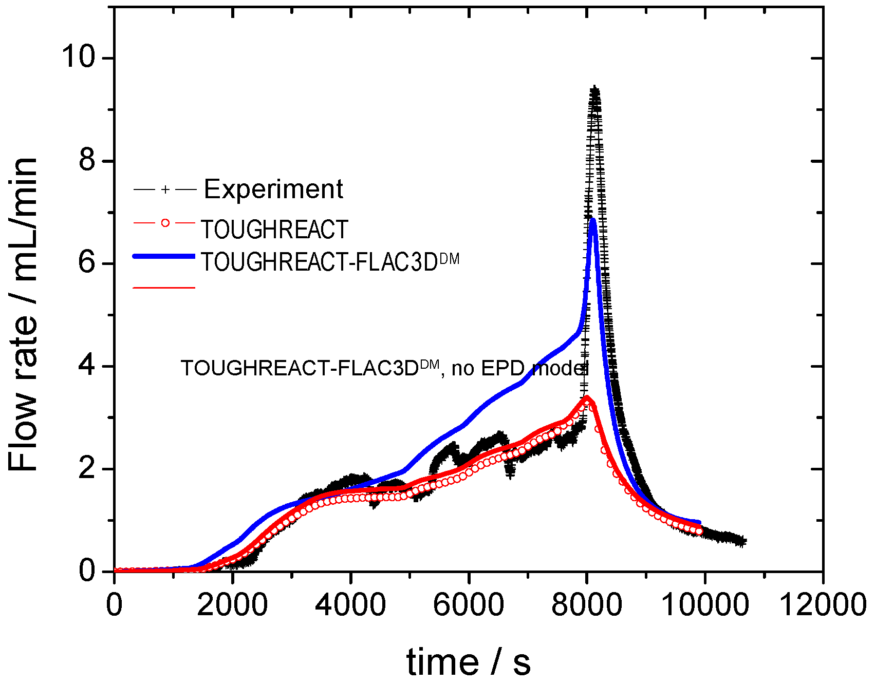
The third validation example consists of simulating one of the laboratory-scale gas-injection tests carried out on Opalinus clay [48,49]. Triaxial loading, strength, and gas-injection tests were performed on clay samples in a standard Kármán cell in a servohydraulic testing machine that allowed for independent control of the radial () and axial stresses () (Figure 10). The size of the cylindrical rock sample was 40 × 160 mm2 (radius × length). The gas (nitrogen) was injected at controlled pressure in a central borehole situated at the bottom of the sample (Figure 10). The gas flow rate at the upper outflow borehole was monitored. The gas-injection tests performed with increased confinement pressure (Pc) were selected for this validation. The confining pressure varied from 10 to 50 bar during the test. Hydrostatic loading was applied with increased confinement and step-wise increase of the gas pressure as shown in Figure 11. The details of the experimental setup and procedures, as well as the rock properties, are available in Reference [48]. The validation results are presented in Figure 12. This figure illustrates the comparison between measured and simulated gas-flow rate. To study the significance of the impact of mechanical damage (e.g., rock microcracking) induced by high gas pressure on the gas migration within the sedimentary rock, two simulation results are presented in Figure 12: (i) a simulation performed by using the TOUGHREACT–FLAC3DDM (THMC tool), i.e., one that includes the developed EPD model (mechanical component); and (ii) a simulation carried out by using TOUGHREACT alone, i.e., one that only considers the multiphase flow modeling capability of TOUGHREACT. From Figure 12, it can be seen that the THMC tool can adequately predict the gas migration within the Opalinus clay. However, Figure 12 shows that TOUGHREACT alone (that does not include a mechanical component) cannot adequately predict the gas flow rate for high gas-injection pressure. These results suggest that the THMC tool can satisfactorily describe the gas migration within the laboratory sample as well as capture the main physical processes that occur in the samples.
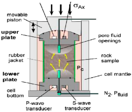
Figure 10.
High-pressure triaxial cell used for the gas-injection tests [48].
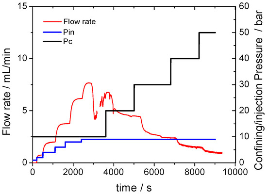
Figure 11.
Gas-injection pressure (Pin) versus time and evolutive confinement pressure (pc) vs out-flow rate.
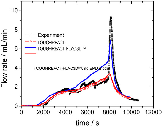
Figure 12.
Comparison between predicted and experimental gas flow rate.
4. Application to Potential Canadian CO2 Disposal Sites
4.1. Introduction
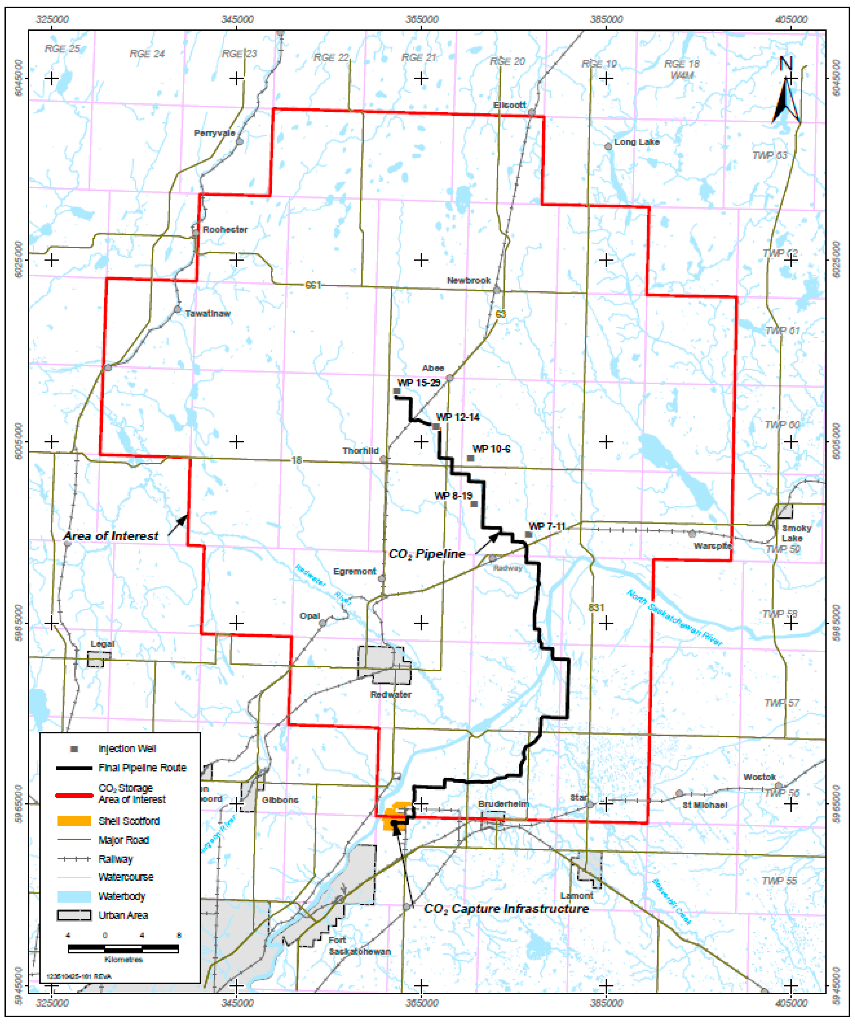
Shell Canada Limited (Shell, Calgary, AB, Canada), on behalf of the Athabasca Oil Sands Project (AOSP), has made an application to the Energy Resources Conservation Board to construct and operate a CCS project (Quest CCS Project) in Alberta (Canada). The goal of the project, which is a key component of the GHG abatement strategy for Shell, is to capture CO2 (at the Scotford upgrader facility), transport it (via pipeline), and permanently store it in the Basal Cambrian Sands (BCS) formation, at a depth of approximately 2 km below ground level (Figure 13). It is expected that approximately three to 10 injection wells will be drilled for injecting CO2 into this deep saline geological formation [50]. The lifespan of the Quest CCS Project is considered to be greater than 25 years [50]. However, concerns have been raised that CO2 leakage from deep geological storage could adversely impact the water quality in the aquifers that overlie the BCS. Therefore, to better understand the consequences of CO2 leakage on the quality of the groundwater present in the project area, numerical simulations have been performed by using the THMC simulator developed in this study. Several results have been obtained. The geological characteristics of the project site, a model setup, and some examples of the typical modeling results with regards to the quality of the groundwater are presented and discussed in the following sections.
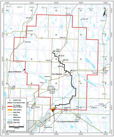
Figure 13.
Quest project area of interest (source: [50]).
4.2. Site Description
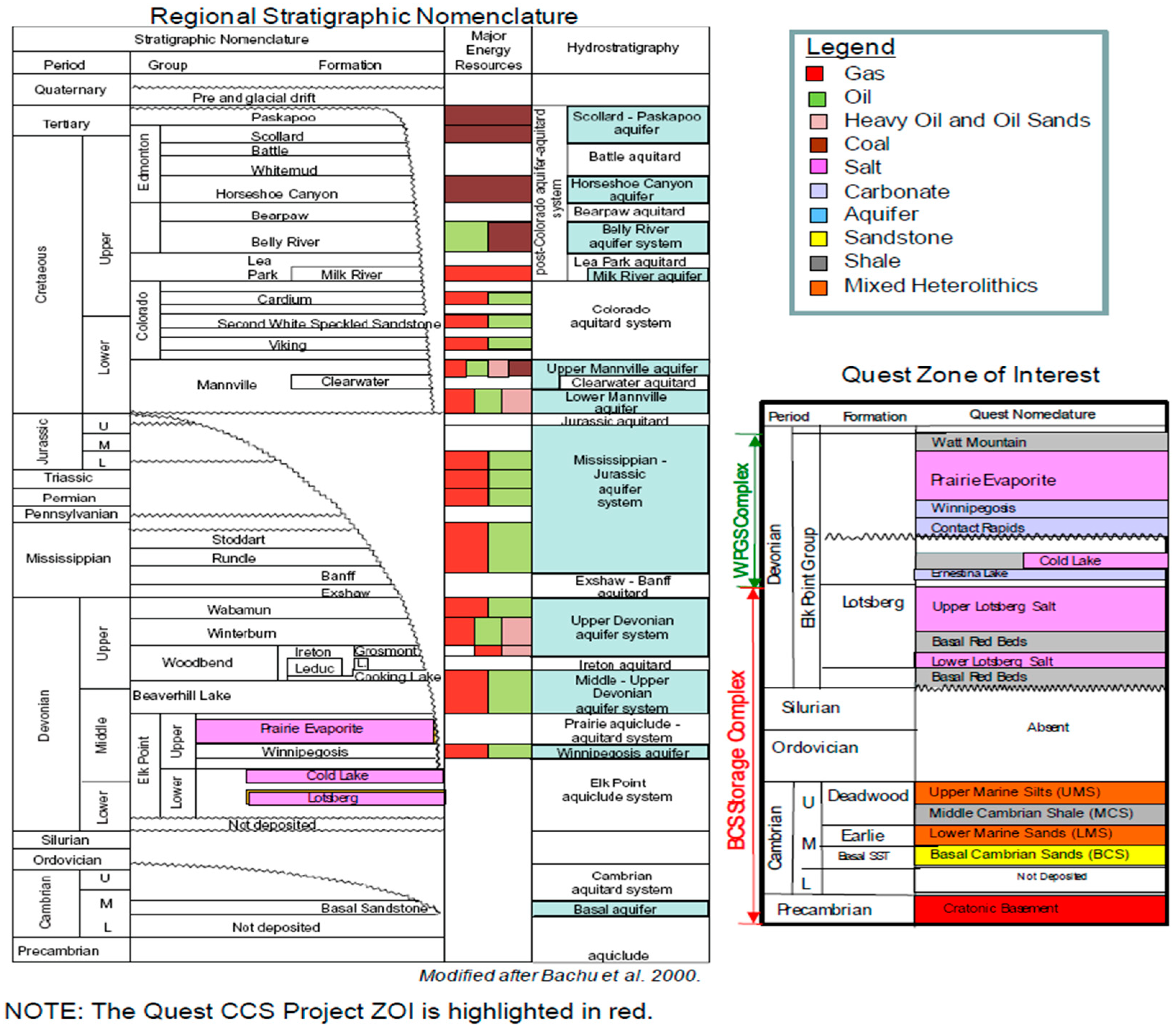
The targeted CO2 injection and disposal zone of the Quest Project, i.e., the BCS, is a deep saline aquifer, which is overlain by a succession of low permeability seals that act as barriers between the BCS and the nonsaline groundwater system. The BCS is in the Western Canadian Sedimentary Basin, which consists of clastic and chemical deposits that are approximately 2000 m in thickness [51]. A stratigraphic description of the region of interest is shown in Figure 14. The BCS is composed of sandstone with upper-fine to upper-coarse and round to subrounded grains [51]. Above the BCS lies a sequence of Middle and Upper Cambrian deposits. The Upper Cretaceous Lea Park Formation is composed of marine shales and siltstones with minor sandstone stringers that have a thickness of over 100 m. The Belly River Group forms the uppermost bedrock in the region, and hosts aquifers above the base of groundwater protection (BGWP) [51]. Quaternary deposits above the bedrock surface include glacially derived deposits with a thickness that varies between 0 and 100 m across the project area [50]. The mechanical properties, porosity, permeability, ground stress, maximum stress direction, and capillary pressure of the rock formations in this area are provided by References [52,53,54,55]. They reported that the level of ground stress at the Quest site can be predicted with the Equation (27):
where Sv is the vertical stress, SHmin is the minimum horizontal stress, and z is the depth.
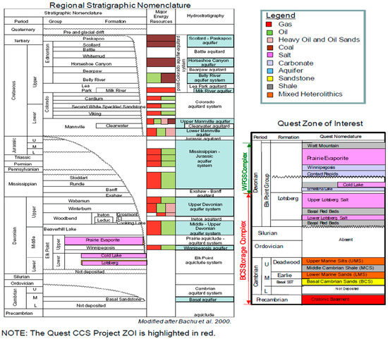
Figure 14.
Geological profile of the southern and central Alberta basin, and the injection site for the Quest CCS project [51].
4.3. Model Setup
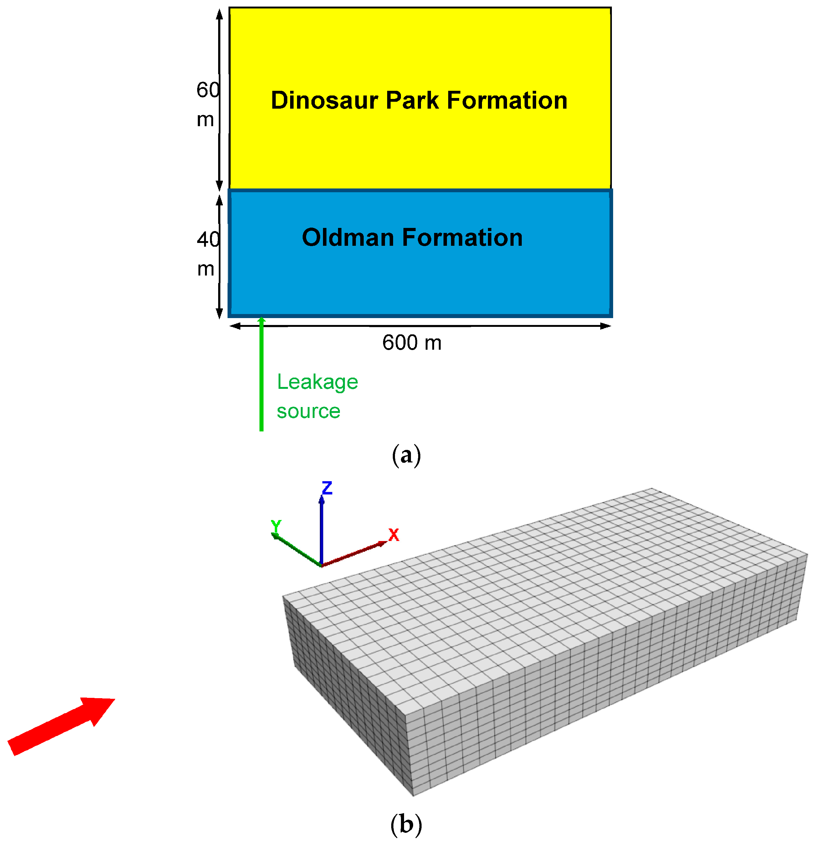
The intrusion of leaking CO2 into the Belly River aquifer and the consequences on water quality were simulated. This targeted aquifer outcrops at the Quest CCS injection site. The overall thickness of the Belly River aquifer is about 100 m, which consists of the Oldman and Dinosaur Park Formations [50]. This formation layer is predominantly interbedded mudstones to very fine grained sandstones with subordinate, but prominent coarser-grained sandstone beds. The Oldman Formation of the Belly River Group overlies the Foremost Formation and subcrops beneath the remainder of the area of interest [50]. The Oldman Formation is made up of continental deposits of interbedded sandstone, siltstone, shale, and coal. The model setup used for most of the simulations is depicted in Figure 15a. The model setup was based on the characteristics of the Belly River aquifer. The dimension of the modeling region was 600 × 300 × 100 m3 for the X × Y × Z coordinate directions, which cover a wide range of typical aquifers as shown in Figure 15b. A three-dimensional FEM gridding of the analysis zones was carried out. The modeling started with the basic assumption that CO2 stored in deep geological units can escape via preferential pathways (Figure 2) and locally enter the Belly River aquifer from below at a constant rate. This is a conservative approach. A similar approach was used by other researchers (e.g., References [11,56,57] to investigate the effect of CO2 leakage on groundwater quality. To deal with the uncertainties associated with the leakage rate or CO2 intrusion rate into the aquifer, scenarios with two leakage rates were defined and taken into consideration in the simulations. The first is considered as a normal scenario (7.5 × 10⁻⁵ kg/s), and the second as the worst-case scenario (conservative approach with a leakage rate at 3.3 × 10⁻³ kg/s). Only simulation results related to the worse scenario are presented below.
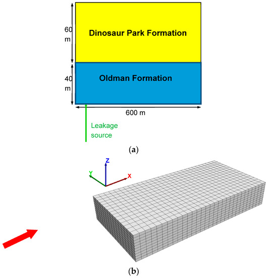
Figure 15.
Schematic view of the model setup and (a) the FEM meshing for (b) modeling the consequences of CO2 intrusion into a shallow aquifer (red arrow indicates groundwater flow direction).
4.4. Initial and Boundary Conditions
Temperature linearly varies with depth, and a geothermal gradient of 2.6 °C per 100 m in depth was assumed, as suggested by Reference [58]. Moreover, it was assumed that the formations were initially water-saturated. A linear hydrostatic condition and the self-weight of the rock formations were assumed to be based on rock density for the starting hydraulic and mechanical conditions. The bottom boundary of the FEM model was fixed in displacement, while the side boundaries were confined with ground stress varying with depth. Groundwater flow directs to the downstream at 1.3 × 10⁻⁹ m/s.
The mineralogical, geomechanical and hydrogeological input data for our model are shown in Table 3, Table 4 and Table 5 and were taken from References [54,55], whereas the data with regard to the chemical composition of the Belly River formation were obtained from the Alberta Geological Survey [59,60]. As a conservative measure, a moderately high level of permeability anisotropy was assumed in this study. The vertical to horizontal ratio of the permeability kv/kh was regarded as 0.1 for both layers of sedimentations in the Belly River formation. The van Genuchten model was used to calculate the capillary pressure and relative permeability of the two-phase flow of CO2 and water. The air-entry value depends on permeability in accordance with the Davies relationship [61]. The hysteresis of the capillary pressure and relative permeability were not considered in the model. Equilibrium runs were conducted prior to simulating CO2 intrusion to create geomechanical and hydrogeological equilibrium, as well as establish the initial chemical composition of the groundwater at equilibrium with the selected mineralogy.

Table 3.
Hydrogeological parameters for the modeling of CO2 intrusion into the shallow aquifers.

Table 4.
Mineral components and abundance in volume.

Table 5.
Geochemistry of groundwater in both the Belly River formation [60] and Alberta basin [66].
With regard to the boundary conditions, side boundaries were set to be impermeable, and a confining stress of 300 bar for the second validation example, and 10 to 50 bar for the third validation example were applied, respectively. The inlet and outlet boundaries were considered permeable, with one end fixed in displacement, while the other end was confined with confinement stress.
4.5. Examples of Results and Discussions
4.5.1. Spatial Distribution and CO2 Evolution
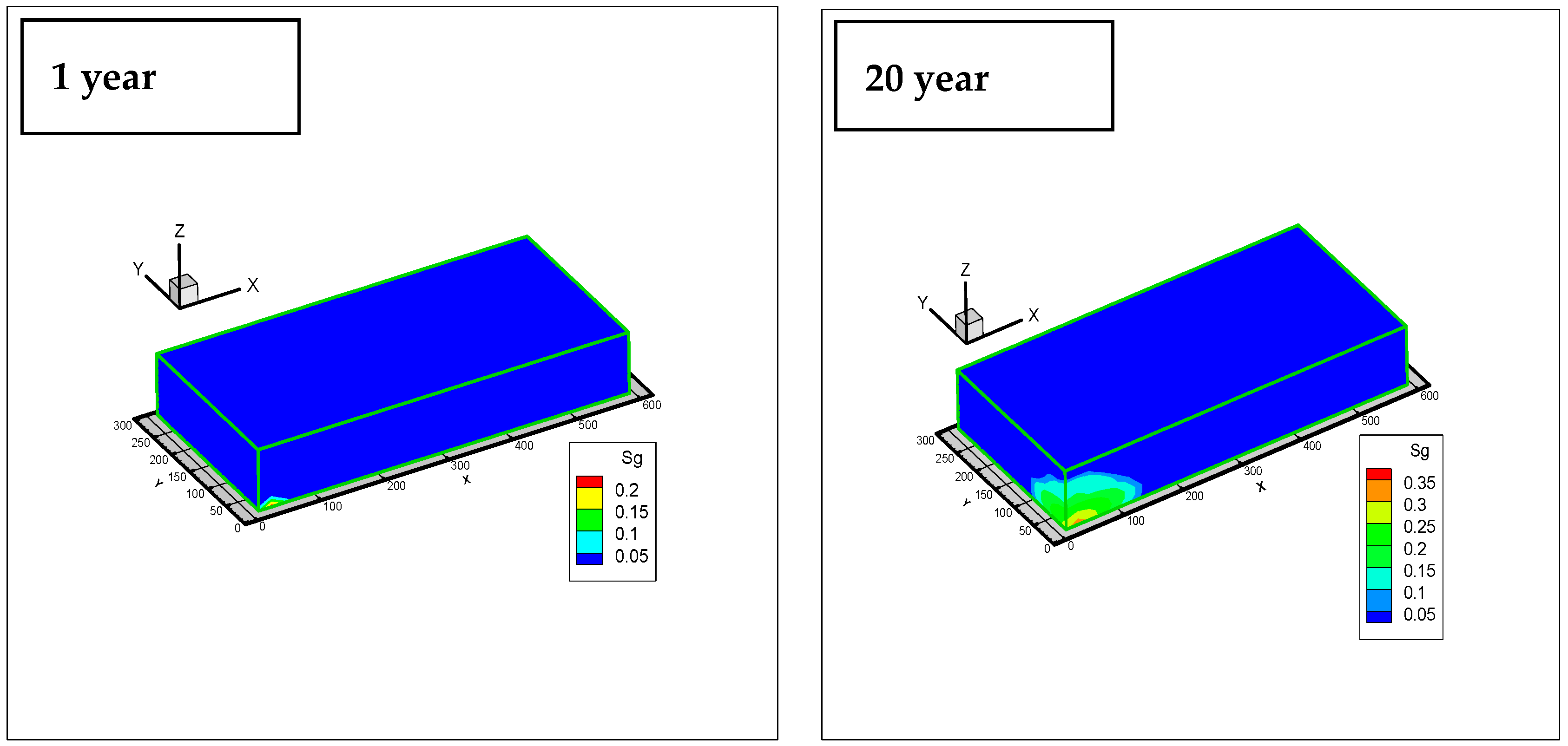
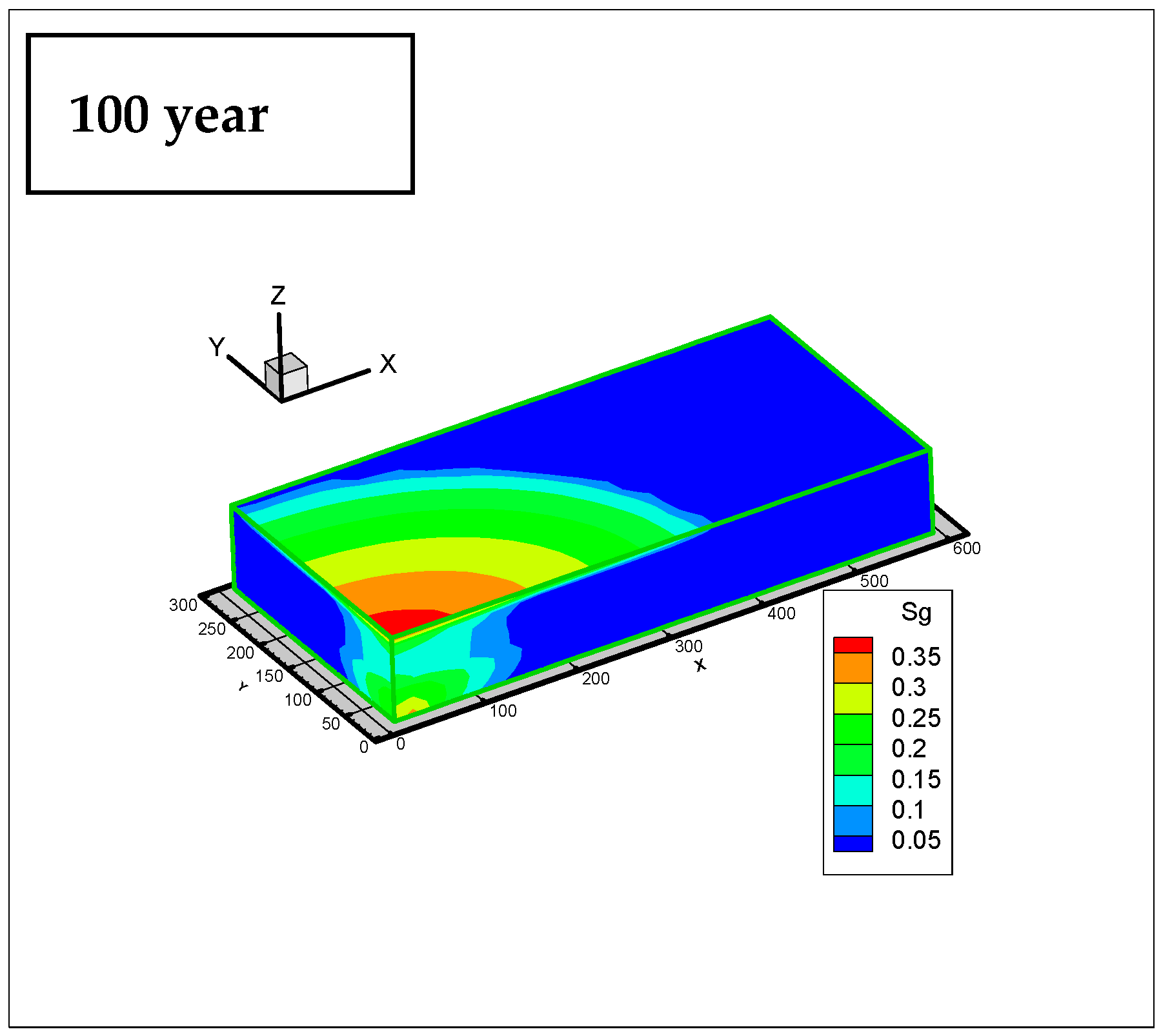
Figure 16 shows the evolution of the leaked CO2 gas concentration in time and space. It can be observed that, after one year of leakage, the CO2 gas phase evolved close to the intrusion area. This CO2 plume then migrated laterally and upward. Once the CO2 plume broke through the lower layer of the Oldman Formation, the higher permeability in the upper layer (Dinosaur Park Formation) resulted in the faster spreading of the CO2. After 100 years of CO2 intrusion, the largest lateral plume appeared in the Dinosaur Park Formation. This can be explained by the higher permeability of this formation.
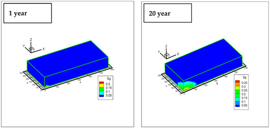
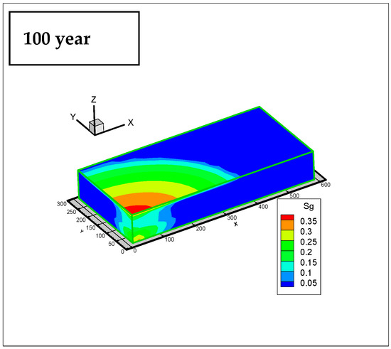
Figure 16.
Contour maps of gas saturation at subsequent durations of CO2 leakage (one year of leakage; 20 years of leakage; 100 years of leakage).
4.5.2. Changes in Groundwater Acidity
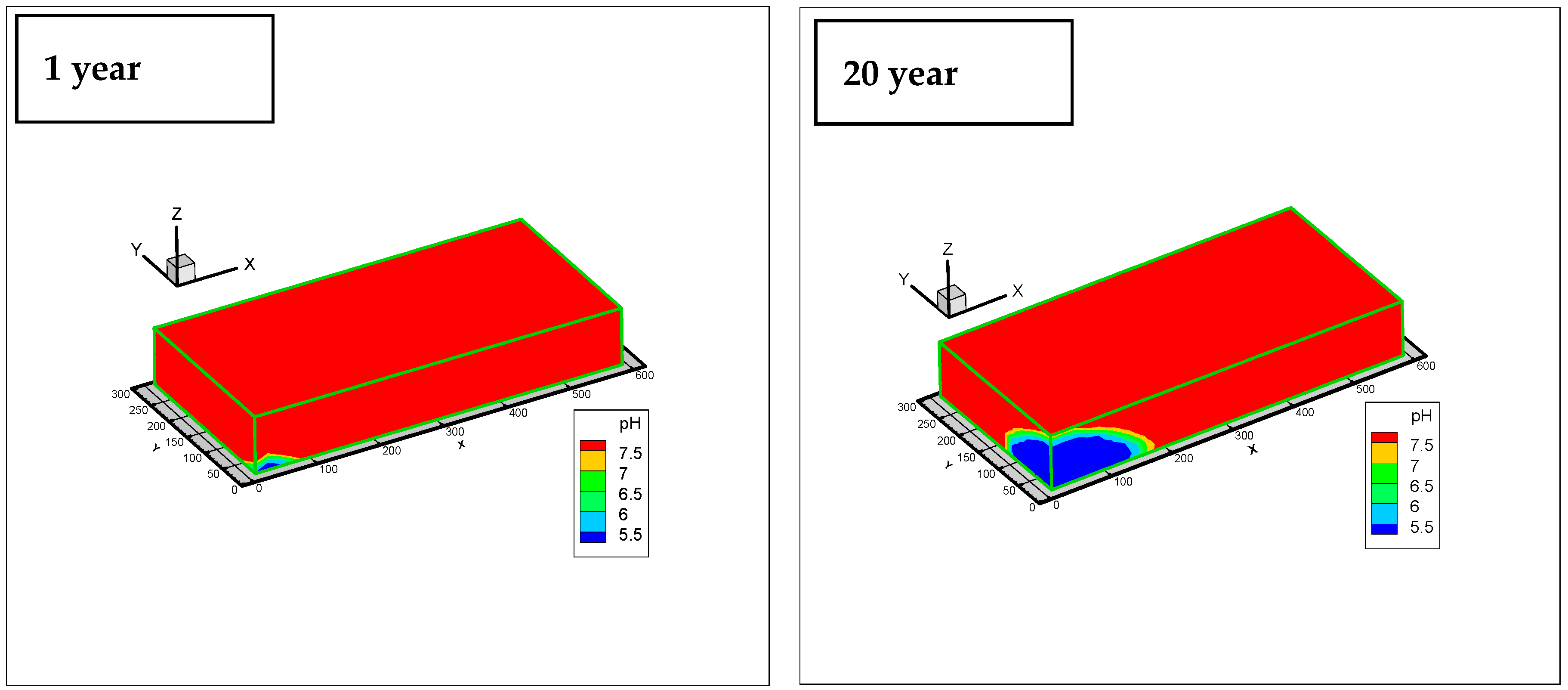
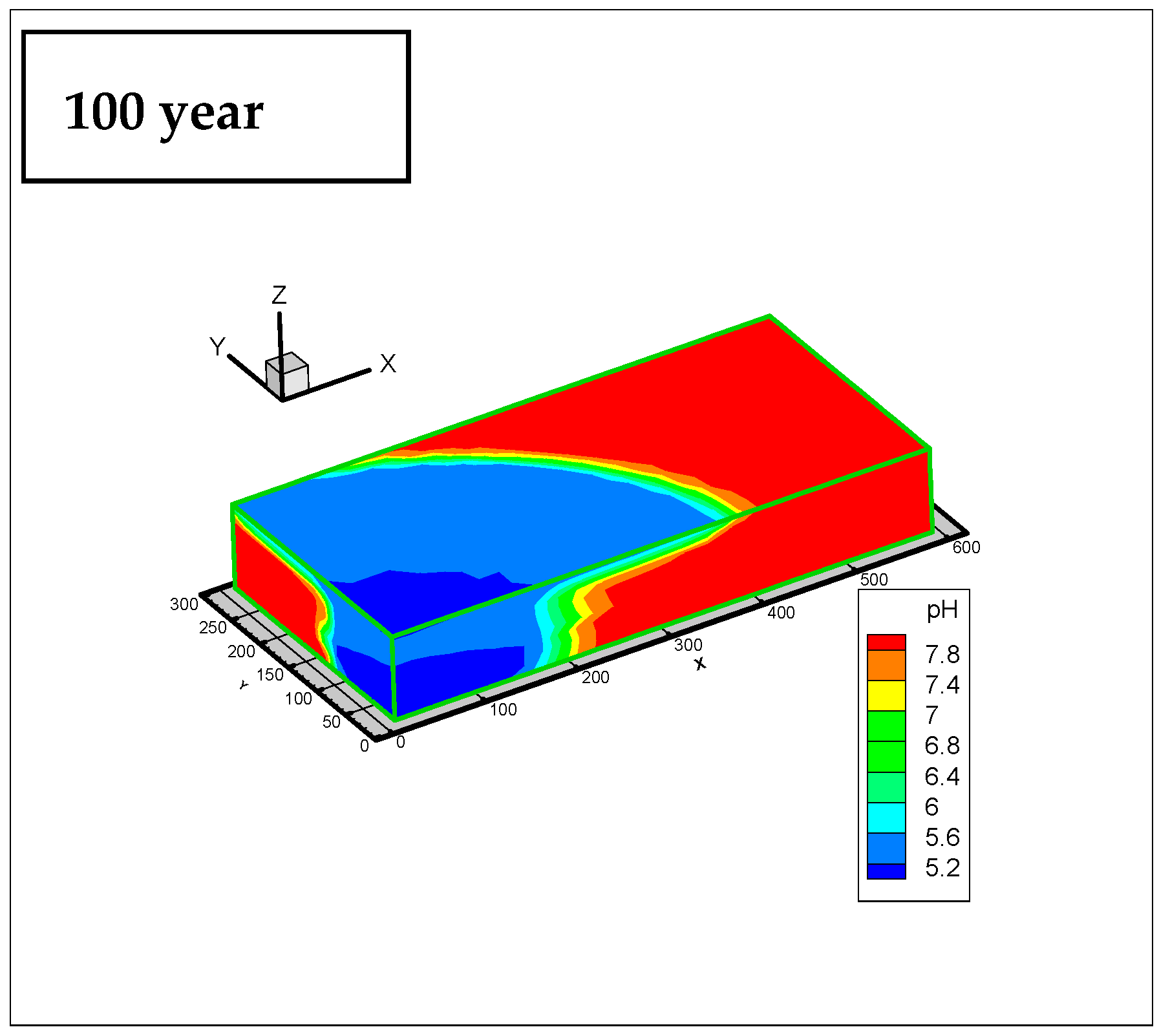
The variation of pH with time is shown in Figure 17. The initial pH of 7.5 sharply declined to 5.5 after 20 years of CO2 leakage. However, only areas close to the intrusion point were affected. Then, the low pH-plume migrated upward and spread laterally up to about 300 m from the intrusion point. The vertical extension can be explained by the upward migration of gaseous CO2 driven by density contrast. Again, the largest lateral pH-plume appeared in the Dinosaur Park Formation due the reasons mentioned before. This observed sensitivity of the aquifer pH to CO2 intrusion might be a useful parameter to detecting any CO2 leakage zones.
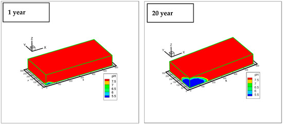
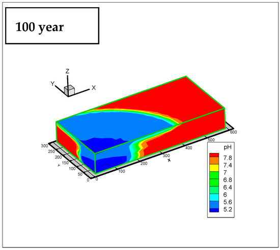
Figure 17.
Contour maps of solution pH at subsequent durations of CO2 leakage (one year of leakage; 20 years of leakage 100 years of leakage).
4.5.3. Prediction of Heavy-Metal Concentrations
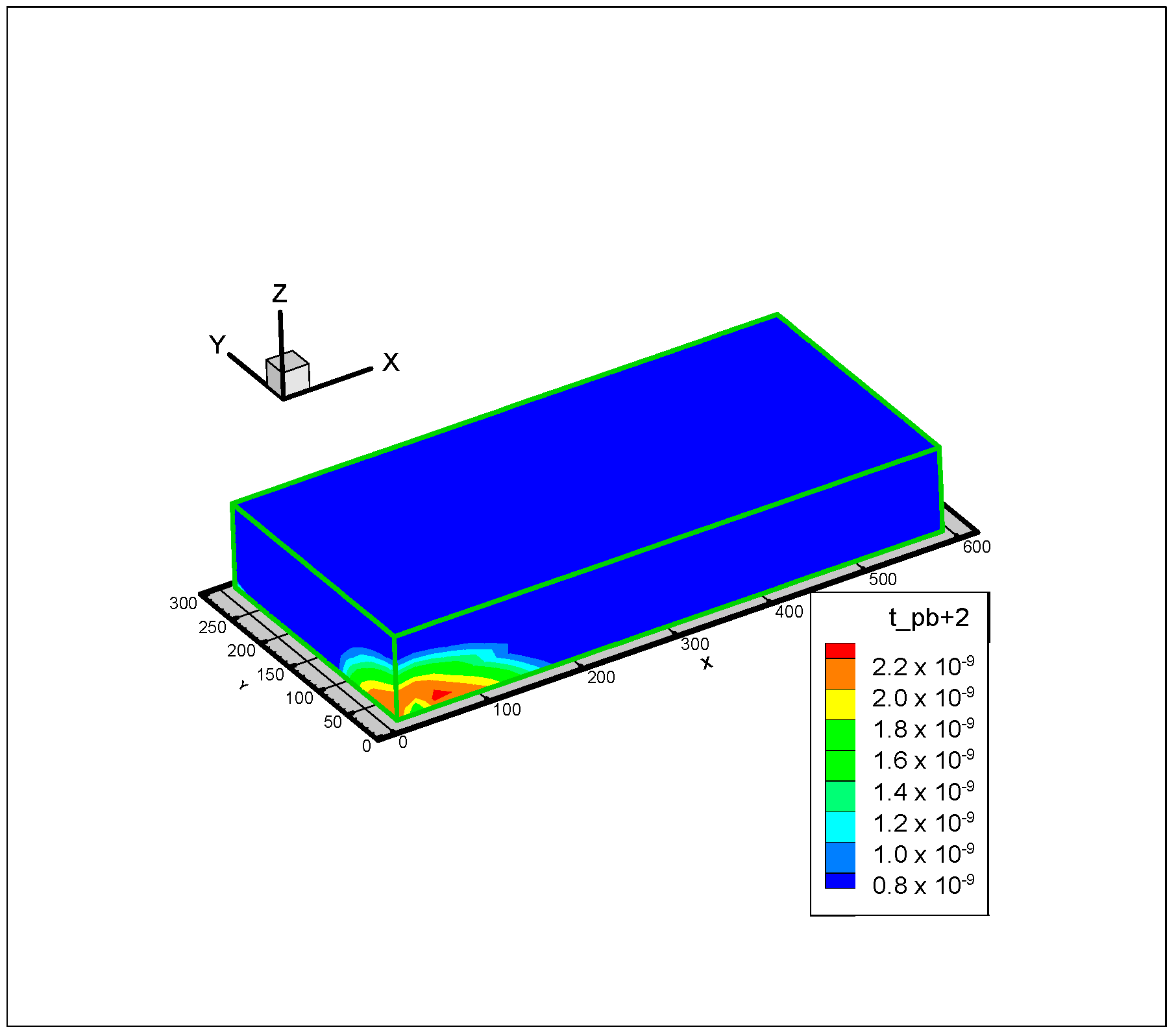
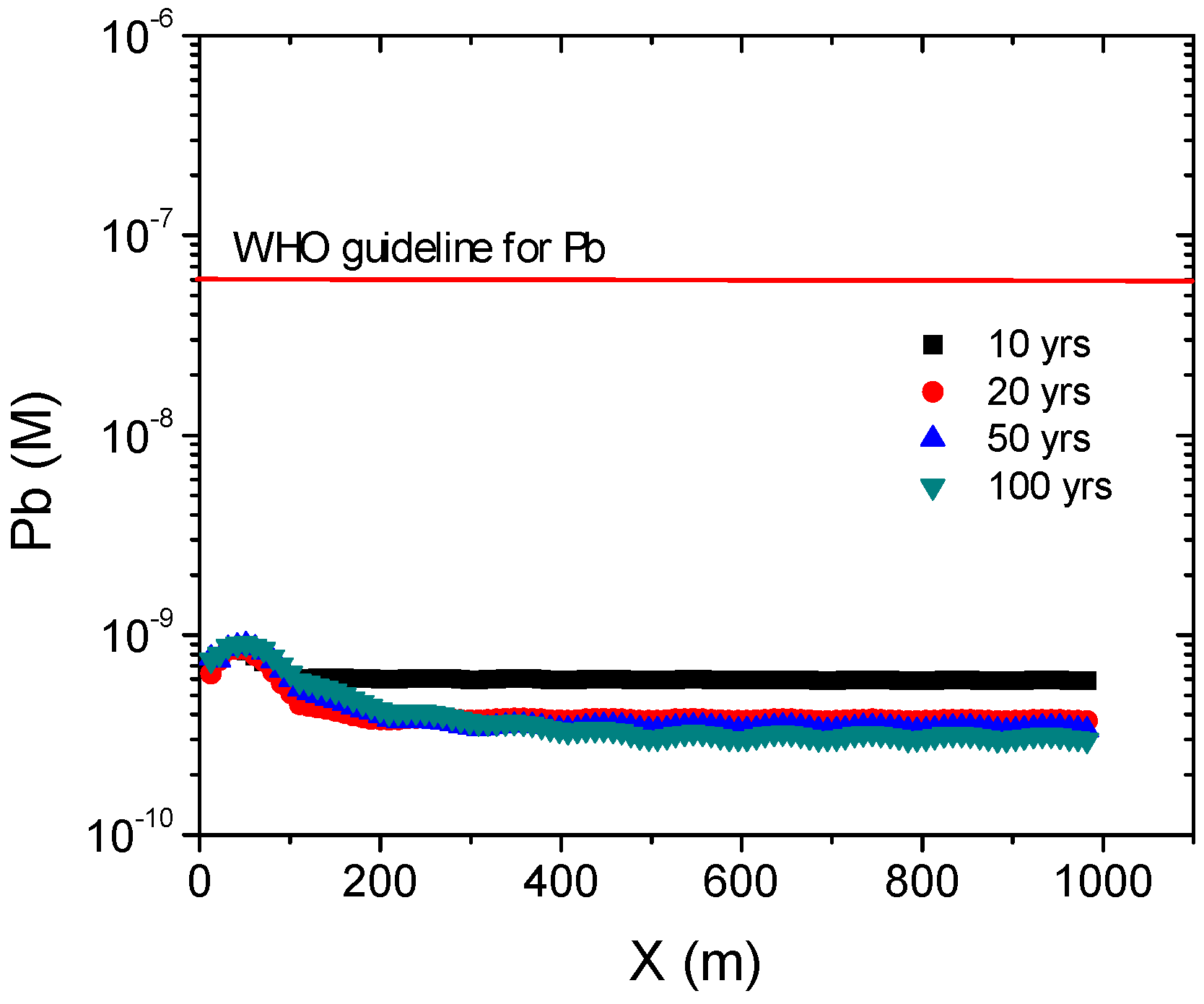
It is well known that, with increasing acidity, contaminants such as heavy metals can be mobilized from aquifer rocks via mineral dissolution and desorption from mineral surfaces. Therefore, the evolution of the concentration of lead (Pb) in the targeted aquifer with time was simulated. Geological survey in the western Canada sedimentary basin revealed considerable abundance of galena grains in surficial sediments (one to four angular to subangular galena grains were recovered in eight of the till samples from NW Alberta, and more other reports of galena in the Devonian formation in the Sedimentary Basin) [64]. It is also highly expected to discover Zn-rich base metal deposits hosted within Cretaceous shale rocks in the Western Canada Sedimentary Basin, including the Belly River formation that is of particular interest to this study. Pb has been detected at various concentrations in some groundwater and formation-water samples [60,66], which indicates the presence of galena in the sediments. A galena proportion of 0.05% was used in this study [63]. The speciation of carbonate greatly depends on the solution pH, and is thus vulnerable to CO2 intrusion. Metal sulfide, however, i.e., galena is more prone to change in redox potential. Figure 18 depicts typical results of the effect of leaking CO2 on the concentration of Pb and its spatial distribution in the aquifer. On the other hand, Figure 19 shows the variation in Pb concentrations in the pore fluid with leakage time at the surface of the aquifer along the X-axis. Modeling results show that the maximum concentrations of Pb after 100 years of CO2 leakage are 1.8 × 10⁻⁹ M. Compared to the WHO standard and Canadian guidelines for drinking water (Table 1 and Table 2), it was found that the water quality of the aquifer still meets the WHO and Canadian standards, as the MAC of Pb was within the drinkable range.
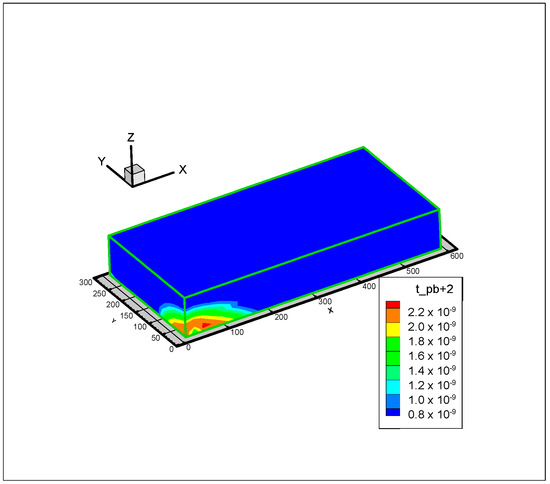
Figure 18.
Contour map of total lead (Pb) concentration after 100 years of CO2 leakage.
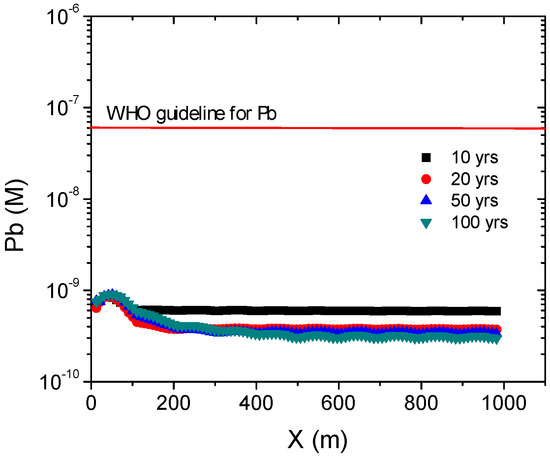
Figure 19.
Variation of Pb concentrations in pore fluid with leakage time on ground surface along X-axis for the worst-case scenario.
5. Summary and Conclusions
A review and analysis of the issues or concerns related to the potential impact of CO2 disposal and leakage on UDW have been carried out. A compilation and analysis of the relevant potential contaminants and existing regulations for UDW quality are being undertaken. The elements presented in the tables in this work are selected based on the most important elements reported in the different literature in terms of freshwater-quality control.
A THMC numerical tool with the capability of modeling CO2 migration and its impact on the quality of aquifer water was developed, taking into consideration all relevant coupled thermal (T), hydraulic (H), chemical (C), and mechanical-damage (M) processes. The simulator has been successfully validated.
The numerical tool has been applied to a Canadian CO2 disposal site (Quest CCS Project site) to assess the consequences of potential CO2 leakage on groundwater quality in the study area (Belly River aquifer). The simulation results have shown that CO2 leakage could result in the increase of the acidity of the Belly River aquifer. This would, in turn, result in an increase in heavy-metal concentrations, such as Pb, in the groundwater. However, the maximum concentrations of Pb after 100 years of CO2 leakage would still be lower than the maximum acceptable concentration of Pb established by WHO and the Canadian drinking-water guidelines. Despite these modeling results, it should be emphasized that there is a lack of sufficient geochemical and mineralogical data at the study area. Furthermore, the kinetics of heterogeneous reactions or the thermodynamic data used in the model are scale- and history-dependent, and cannot be reliably quantified. General lack of a good knowledge of subsurface heterogeneities could also trigger or limit CO2 migration. Providing a perfect match in meshing between FLAC3D and TOUGHREACT is crucial to generate a conceptual model for a geometry.
Therefore, it is important that further studies be conducted to address the issues mentioned above.
Author Contributions
Funding acquisition and supervision, M.F.; conceptualization, M.F and Z.L.; methodology, software, validation and analysis, Z.L., A.G and M.F.; original draft preparation, Z.L., A.G. and M.F.; final review and editing, Z.L., A.G. and M.F.
Funding
This research was funded by Carbon Management Canada (CMC) and the University of Ottawa.
Conflicts of Interest
The authors declare no conflict of interest. The funders had no role in the design of the study; in the collection, analyses, or interpretation of data; in the writing of the manuscript, or in the decision to publish the results.
References
- WMO, Working Group I. Climate Change 2001: The Scientific Basis; Technical Report; Cambridge University Press: Cambridge, UK, 2001; p. 94. [Google Scholar]
- Pearson, D. The Potential Impact of Climate Change on the Mining Industry in Canada. In Proceedings of the Mining and Environment, Sudbury, ON, Canada, 25–28 May 2003; p. 12. [Google Scholar]
- Intergovernmental Panel on Climate Change (IPCC). Climate Change 2014—The Synthesis Report of the Fifth Assessment Report of the Intergovernmental Panel on Climate Change; The Core Writing Team, Pachauri, R.K., Meyer, L., Eds.; Intergovernmental Panel on Climate Change: Geneva, Switzerland, 2014; p. 139.
- Solomon, S. Carbon Dioxide Storage: Geological Security and Environmental Issues—Case Study on the Sleipner Gas Field in Norway. Bellona Report. 2007. Available online: https://network.bellona.org/content/uploads/sites/3/Case_Study_on_the_Sleipner_Gas_Field_in_Norway.pdf (accessed on 24 October 2018).
- Shaffer, G. Long-term effectiveness and consequences of carbon dioxide sequestration. Nat. Geosci. 2010, 3, 464–467. [Google Scholar] [CrossRef]
- Alonso, J.; Navarro, V.; Calvo, B.; Asensio, L. Hydro-mechanical analysis of CO2 storage in porous rocks using a critical state model. Int. J. Rock Mech. Min. Sci. 2012, 54, 19–26. [Google Scholar] [CrossRef]
- Porter, M.L.; Plampin, M.; Pawar, R.; Illangasekare, T. CO2 leakage in shallow aquifers: A benchmark modeling study of CO2 gas evolution in heterogeneous porous media. Int. J. Greenh. Gas Control 2015, 39, 51–61. [Google Scholar] [CrossRef]
- Yang, C.; Dai, Z.; Romanak, K.D.; Hovorka, S.D.; Treviño, R.H. Inverse Modeling of Water-Rock-CO2 Batch Experiments: Potential Impacts on Groundwater Resources at Carbon Sequestration Sites. Environ. Sci. Technol. 2014, 48, 2798–2806. [Google Scholar] [CrossRef] [PubMed]
- Bacon, D.H.; Qafoku, N.P.; Dai, Z.; Brown, C.F. Modeling the impact of carbon dioxide leakage into an unconfined, oxidizing carbonate aquifer. Int. J. Greenh. Gas Control 2016, 44, 190–299. [Google Scholar] [CrossRef]
- Birkholzer, J.; Daley, T.; Jordan, P.; Oldenburg, C.; Rutqvist, J. National Risk Assessment Partnership (NRAP). 2011. Available online: http://esd.lbl.gov/research/programs/gcs/projects/nrap/ (accessed on 24 October 2018).
- Apps, J.A.; Zheng, L.; Zhang, Y.; Xu, T. Evaluation of potential changes in groundwater quality in response to CO2 leakage from deep geologic storage. Transp. Porous Media 2010, 82, 215–246. [Google Scholar] [CrossRef]
- Wainwright, H.; Finsterle, S.; Zhou, Q.; Birkholzer, J.T. Modeling the Performance of Large-Scale CO2 Storage Systems: A Comparison of Different Sensitivity Analysis Methods. Int. J. Greenh. Gas Control 2013, 17, 189–205. [Google Scholar] [CrossRef]
- Kharaka, Y.K.; Thordsen, J.J.; Kakouros, E.; Ambats, G.; Herkelrath, W.N.; Beers, S.R.; Birkholzer, J.T.; Apps, J.A.; Spycher, N.F.; Zheng, L.; et al. Changes in the Chemistry of Shallow Groundwater Related to the 2008 Injection of CO2 at the ZERT Field Site, Bozeman, Montana. Environ. Earth Sci. 2010, 60, 273–284. [Google Scholar] [CrossRef]
- Gunter, W.D.; Perkins, E.H.; Hutcheon, I. Aquifer disposal of acid gases: modeling of water-rock reactions for trapping of acid wastes. Appl. Geochem. 2000, 15, 1085–1095. [Google Scholar] [CrossRef]
- Rutqvist, J.; Tsang, C.F. A study of caprock hydromechanical changes associated with CO2-injection into a brine formation. Environ. Geol. 2002, 42, 296–305. [Google Scholar] [CrossRef]
- Azaroual, M.; Kervevan, C.; Durance, M.V.; Durst, P. SCALE2000: A reaction-transport software dedicated to thermo-kinetic prediction and quantification of scales. Applicability to desalination problems. Desalination 2004, 156, 409–419. [Google Scholar] [CrossRef]
- Johnson, J.W.; Nitao, J.J.; Steefel, C.; Knaus, K.G. Reactive transport modeling of geological CO2 sequestration in saline aquifers; the influence of intra-aquifer shales and the relative effectiveness of structural, solubility, and mineral trapping during prograde and retrograde sequestration. In Proceedings of the First Annual Conference on Carbon Sequestration, Washington, DC, USA, 14–17 May 2001. [Google Scholar]
- Johnson, J.W.; Nitao, J.J.; Knauss, K.G. Reactive transport modeling of CO2 storage in saline aquifers to elucidate fundamental processes, trapping mechanisms, and sequestration partitioning. In Geologic Storage of Carbon Dioxide; Special Publication 233; Baines, S.J., Worden, R.H., Eds.; Geological Society: London, UK, 2004; pp. 107–128. [Google Scholar]
- Knauss, K.G.; Johnson, J.W.; Steefel, C.I. Evaluation of the impact of CO2, co-contaminant gas, aqueous fluid, and reservoir rock interactions on the geologic sequestration of CO2. Chem. Geol. 2005, 217, 339–350. [Google Scholar] [CrossRef]
- Gaus, I.; Azarouai, M.; Czernichowski, L. Reactive transport modeling of the impact of CO2 injection on the clayey cap rock at Sleipner (North Sea). Chem. Geol. 2005, 217, 319–337. [Google Scholar] [CrossRef]
- André, L.; Audigane, P.; Azaroual, M.; Menjoz, A. Numerical modeling of fluid-rock chemical interactions at the supercritical CO2–liquid interface during supercritical CO2 injection into a carbonate reservoir, the Dogger aquifer (Paris Basin, France). Energy Convers. Manag. 2007, 48, 1782–1797. [Google Scholar] [CrossRef]
- Audigane, P.; Gaus, I.; Czernichowski-Lauriol, I.; Pruess, K.; Xu, T. Two dimensional reactive transport modeling of CO2 injection in a saline aquifer at the Sleipner site, North Sea. Am. J. Sci. 2007, 307, 974–1008. [Google Scholar] [CrossRef]
- Chang, K.W.; Minkoff, S.E.; Bryant, S.L. Modeling leakage through faults of CO2 stored in an aquifer. In Proceedings of the SPE Annual Technical Conference and Exhibition, Denver, CO, USA, 21–24 September 2008. [Google Scholar]
- Viswanathan, H.; Pawar, R.J.; Staufer, P.H.; Kaszuba, J.P.; Carey, J.W.; Olsen, S.C.; Keating, G.N.; Kevetski, D.; Guthrie, G.D. Development of a hybrid process and system model for the assessment of wellbore leakage at a geologic CO2 sequestration site. Environ. Sci. Technol. 2008, 42, 7280–7286. [Google Scholar] [CrossRef] [PubMed]
- Davis, J.P.; Davis, D.K. Stress-dependent permeability: Characterization and modeling. Soc. Petrol. Eng. 1999, 6, 224–235. [Google Scholar]
- Kolditz, O.; Bauer, S.; Bilke, L.; Böttcher, N.; Delfs, J.O.; Fischer, T.; Görke, U.J.; Kalbacher, T.; Kosakowski, G.; McDermott, C.I.; et al. OpenGeoSys: An open-source initiative for numerical simulation of thermo-hydro-mechanical/chemical (THM/C) processes in porous media. Environ. Earth Sci. 2012, 67, 589–599. [Google Scholar] [CrossRef]
- Shevalier, M.; Nightingale, M.; Mayer, B.; Hutcheon, I. TOUGHREACT modeling of the fate of CO2 injected into a H2S containing saline aquifer: The example of the Wabamum Area Sequestration Project (WASP). Energy Procedia 2011, 4, 4403–4410. [Google Scholar] [CrossRef]
- Spycher, N.; Pruess, K. A model for thermophysical properties of CO2-brine mixtures at elevated temperatures and pressures. In Proceedings of the Thirty-Sixth Workshop on Geothermal Reservoir Engineering, Stanford University, Stanford, CA, USA, 31 January–2 February 2011. [Google Scholar]
- Nogues, J.P.; Fitts, J.P.; Celia, M.A.; Peters, C.A. Permeability evolution due to dissolution and precipitation of carbonates using reactive transport modeling in pore networks. Water Resour. Res. 2013, 49, 6006–6021. [Google Scholar] [CrossRef]
- Nasir, O.; Fall, M.; Evgin, E. A Simulator for Modeling of Porosity and Permeability Changes in Near Field Sedimentary Host Rocks under Climate Changes Influences. Tunn. Undergr. Space Technol. 2014, 42, 122–135. [Google Scholar] [CrossRef]
- Ladubec, C.; Gracie, R.; Craig, J. An XFEM Model for Carbon Sequestration. Int. J. Numer. Methods Eng. 2014. [CrossRef]
- Yang, C.; Hovorka, S.D.; Young, M.H.; Trevino, R. Geochemical sensitivity to CO2 leakage: Detection in potable aquifers at carbon sequestration sites. Greenh. Gases Sci. Technol. 2014, 4, 384–399. [Google Scholar] [CrossRef]
- Benson, S.M.; Myer, L. Monitoring to ensure safe and effective geologic sequestration of carbon dioxide. In Proceedings of the Intergovernmental Panel on Climate Change (IPCC) Workshop on Carbon Sequestration, Regina, SK, Canada, 18–22 November 2002. [Google Scholar]
- Gaus, I. Role and impact of CO2-rock interactions during CO2 storage in sedimentary rocks. Int. J. Greenh. Gas Control 2010, 4, 73–89. [Google Scholar] [CrossRef]
- Rutqvist, J. Status of the TOUGH-FLAC simulator and recent applications related to coupled fluid flow and crustal deformations. Comput. Geosci. 2011, 37, 739–750. [Google Scholar] [CrossRef]
- Li, Z.; Fall, M. Coupled Thermo-Hydro-Mechanical-Geochemical Model for the Assessment of Groundwater Quality due to Impacts from Geological Sequestration of CO2. In Proceedings of the 66th Canadian Geotechnical Conference (CGC), Montreal, QC, Canada, 29 September–3 October 2013. [Google Scholar]
- Li, Z.; Fall, M. A modeling tool for assessment of potential groundwater contamination in response to CO2 leakage from geological disposal of CO2. In Proceedings of the 3rd Climate Change Technology Conference, Montreal, QC, Canada, 27–29 May 2013. [Google Scholar]
- ITASCA. Flac3D: Fast Lagrangian Analysis of Continua in 3 Dimensions; ITASCA Consulting Group Inc.: Minneapolis, MN, USA, 2009. [Google Scholar]
- Xu, T.; Spycher, N.; Sonnenthal, E.; Zheng, L.; Pruess, K. TOUGHREACT User’s Guide: A Simulation Program for Non-Isothermal Multiphase Reactive Transport in Variably Saturated Geologic Media, Version 2.0; Lawrence Berkeley National Laboratory: Berkeley, CA, USA, 2012.
- Xu, T.; Pruess, K. Modeling multiphase non-isothermal fluid flow and reactive geochemical transport in variably saturated fractured rocks: 1Methodology. Am. J. Sci. 2001, 301, 16–33. [Google Scholar] [CrossRef]
- Yu, Z.; Liu, L.; Yang, S.; Li, S.; Yang, Y. An experimental study of CO2–brine–rock interaction at in situ pressure–temperature reservoir conditions. Chem. Geol. 2012, 326–327, 88–101. [Google Scholar] [CrossRef]
- Xu, X.; Song, C.; Miller, B.G.; Scaroni, A.W. Adsorption separation of carbon dioxide from flue gas of natural gas-fired boiler by a novel nanoporous “molecular basket” adsorbent. Fuel Process. Technol. 2005, 86, 1457–1472. [Google Scholar] [CrossRef]
- Tsang, C.-F.; Birkholzer, J.; Rutqvist, J. A comparative review of hydrologic issues involved in geologic storage of CO2 and injection disposal of liquid waste. Environ. Geol. 2008, 54, 1723–1737. [Google Scholar] [CrossRef]
- Kachanov, L.M. Time of the rupture process under creep conditions. Isv. Akad. Nauk. SSR. Otd Tekh. Nauk. 1958, 8, 26–31. [Google Scholar]
- Lemaitre, J. Evaluation and dissipation of damage in metals submitted to dynamic loading. In Proceedings of the I.C.M.I., Kyoto, Japan, 1971. [Google Scholar]
- Lemaitre, J.; Chaboche, J.L. Mechanics of Materials; Cambridge University Press: Cambridge, UK, 1990. [Google Scholar]
- Hildenbrand, A.; Schlömer, S.; Krooss, B.M. Gas breakthrough experiments on fine-grained sedimentary rocks. Geofluids 2002, 2, 3–23. [Google Scholar] [CrossRef]
- Popp, T.; Salzer, K.; Minkley, W. Influence of bedding planes to EDZ-evolution and the coupled HM properties of Opalinus Clay. Phys. Chem. Earth Parts A/B/C 2008, 33, 374–387. [Google Scholar] [CrossRef]
- Popp, T.; Salzer, K. Anisotropy of seismic and mechanical properties of Opalinus clay during triaxial deformation in a multi-anvil apparatus. Phys. Chem. Earth Parts A/B/C 2007, 32, 879–888. [Google Scholar] [CrossRef]
- Stantec, C.I. Quest Carbon Capture and Storage Project; Project Description Shell Canada Limited: Calgary, AB, Canada, 2010; Volume 1. [Google Scholar]
- ERCB. Bulletin 2007-10: Alberta’s Base of Groundwater Protection (BGWP) Information; Energy Resources Conservation Board: Edmonton, AB, Canada, 2007.
- Shell Application for Quest Carbon Capture and Storage—Groundwater Review; NE 19-059-20 W4M Hydrogeological Consultants Ltd. Prepared for Ackroyd LLP; Hydrogeological Consultants Ltd.: Edmonton, AB, Canada, 2012; p. 12.
- Bachu, S.; Michael, K. Hydrogeology and Stress Regime of the Upper Cretaceous-Tertiary Coal-Bearing Strata in Alberta; Alberta Energy and Utilities Board, Alberta Geological Survey: Edmonton, AB, Canada, 2002. [Google Scholar]
- Bachu, S.; Brulotte, M.; Grobe, M.; Stewart, S. Suitability of the Alberta Subsurface for Carbon-Dioxide Sequestration in Geological Media; Report Earth Sciences Report 00-11; Alberta Energy and Utilities Board, Alberta Geological Survey: Edmonton, AB, Canada, 2000. [Google Scholar]
- Bachu, S.; Buschkuehle, M.; Haug, K.; Michael, K. Subsurface Characterization of the Edmonton-Area Acid-Gas Injection Operations; Energy Resources Conservation Board, Alberta Geological Survey: Edmonton, AB, Canada, 2008.
- Birkholzer, J.T.; Zhou, Q.; Tsang, C.F. Large-scale impact of CO2 storage in deep saline aquifers: A sensitivity study on the pressure response in stratified systems. Int. J. Greenh. Gas Control 2009, 3, 181–194. [Google Scholar] [CrossRef]
- Birkholzer, J.T.; Zhou, Q. Basin-scale hydrogeologic impacts of CO2 storage: Capacity and regulatory implications. Int. J. Greenh. Gas Control 2009, 3, 745–756. [Google Scholar] [CrossRef]
- Hitchon, B. Geochemical Studies–3 Ceochemistry of Some Alberta Shales and Associated Kerogen; Alberta Geological Survey: Edmonton, AB, Canada, 1993. [Google Scholar]
- Lemay, T.G. Chemical and Physical Hydrogeology of Coal, Mixed Coal-Sandstone and Sandstone Aquifers from Coal-Bearing Formations in the Alberta Plains Region, Alberta; Alberta Energy and Utilities Board, Alberta Geological Survey: Edmonton, AB, Canada, 2003. [Google Scholar]
- Lemay, T.G.; Konhauser, K.O. Water Chemistry of Coalbed Methane Reservoirs; Alberta Energy and Utilities Board: Edmonton, AB, Canada, 2006. [Google Scholar]
- Davies, P.B. Evaluation of the Role of Threshold Pressure in Controlling Flow of Waste-Generated Gas into Bedded Salt at the Waste Isolation Pilot Plant (WIPP); Report SAND 90-3246; Sandia National Laboratory: Albuquerque, NM, USA; Livermore, CA, USA, 1991.
- Eberth, D.; Hamblin, A. Tectonic, stratigraphic, and sedimentologic significance of a regional discontinuity in the upper Judith River Group (Belly River wedge) of southern Alberta, Saskatchewan, and Northern Montana. Can. J. Earth Sci. 1993, 30, 174–200. [Google Scholar] [CrossRef]
- Lerbekmo, J.F. Petrology of the belly river formation, southern Alberta foothills. Sedimentology 1963, 2, 54–86. [Google Scholar] [CrossRef]
- Paulen, R.C.; Paradis, S.; Plouffe, A.; Smith, I.R. Pb and S isotopic composition of indicator minerals in glacial sediments from NW Alberta, Canada: Implications for Zn-Pb base metal exploration. Geochem. Explor. Environ. Anal. 2011, 11, 309–320. [Google Scholar] [CrossRef]
- Longstaffe, F.J.; Ayalon, A. Oxygen Isotope Studies of Diagenesis and Pore-Water Evolution in the Western Canada Sedimentary Basin: Evidence from the Upper Cretaceous Basal Belly River Sandstone, Alberta. J. Sediment. Res. 1991, 58, 489–505. [Google Scholar]
- Cheung, K.; Mayer, B. Chemical and Isotopic Characterization of Shallow Groundwater from Selected Monitoring Wells in Alberta: Part I: 2006–2007; Alberta Environment: Edmonton, AB, Canada, 2009. [Google Scholar]
© 2018 by the authors. Licensee MDPI, Basel, Switzerland. This article is an open access article distributed under the terms and conditions of the Creative Commons Attribution (CC BY) license (http://creativecommons.org/licenses/by/4.0/).

