Article

Designing a Novel THz Band 2-D Wide-Angle Scanning Phased-Array Antenna Based on a Decoupling Surface

Department of Information Engineering, Engineering University of PAP, Xi’an 710086, China
*
Author to whom correspondence should be addressed.
Appl. Sci. 2024, 14(19), 8618; https://doi.org/10.3390/app14198618
Submission received: 1 September 2024 / Revised: 21 September 2024 / Accepted: 23 September 2024 / Published: 24 September 2024
(This article belongs to the Section Electrical, Electronics and Communications Engineering)

Abstract

:
This paper proposes a novel THz band 2-D wide-angle scanning phased-array antenna (PAA) based on a decoupling surface. The simulated S11 bandwidth under periodic boundary conditions is 106–119 GHz, with stable gain within the bandwidth. The designed decoupling surface effectively reduces the coupling between elements, and the simulated active VSWR performance and ground surface current distribution under periodic boundary conditions confirm this. An 8 × 8 (64-element) planar PAA is modeled and simulated in CST2022 to verify the beam-scanning performance of the PAA. According to the simulation results, a 2-D wide-angle scanning of ±48° is achieved in the 106–114 GHz range, while in the 115–119 GHz range, a wide-angle scanning of ±48° is achieved on the E-plane, and the beam-scanning range on the H-plane reaches ±40°. Moreover, the normal peak gain is stably maintained at 21.9–22.8 dBi, with a normalized radiation efficiency as high as 95%, and the scanning radiation efficiency is higher than 81%. Due to its stable gain and 2-D wide-angle scanning performance, the proposed PAA has a broad application prospect in terahertz wireless communication equipment.

1. Introduction

THz band communication technology has garnered significant attention due to its potential for high data transmission rates, and it is likely to be utilized in future 6G communications [1,2,3,4,5]. The current research focus is on enhancing the transmission power of THz signals, optimizing beam control technology, and developing efficient integrated-circuit designs. The main beam control technologies currently include transmission array beam control [6,7,8,9], reflection array beam control [10,11], and phased-array technology [12]. Among them, phased-array technology has become a key technology for THz beam control because it can support a wider available frequency band, as well as spatial coexistence and multiplexing. By adjusting the phase of each antenna element in the array, the phased array can precisely control the radiation beam, thereby improving signal directionality and enhancing communication quality. However, the design of phased-array antennas (PAAs) for the THz band is extremely challenging due to the extremely small size of antennas in this frequency range. In addition, the operating bandwidth of the THz band is generally wide, but achieving stable gain within a wide operating bandwidth is also not easy.
To achieve precise control of the beam in the THz band, beam control chips are indispensable. The fabrication processes for THz beam control chips mainly include compound semiconductor processes and silicon-based processes. Compound semiconductor processes, such as gallium arsenide (GaAs), indium phosphide (InP), and gallium nitride (GaN), offer advantages like high output power and low noise figure for reception. However, they have the drawbacks of low integration density and high cost. Silicon-based processes, including complementary metal-oxide-semiconductor (CMOS) and silicon–germanium (SiGe), may have average performance but benefit from high integration density and low cost. In [13], the authors introduce a scalable approach for implementing millimeter-wave and THz fully integrated circuits based on standing waves which addresses the challenges of power generation and beam steering in a compact form factor. In [14], working on a scalable THz 2-D PAA, the authors further emphasize the potential for high-resolution imaging and spectroscopy in the millimeter-wave and THz frequencies. The fully integrated 16-element PAA transmitter in SiGe BiCMOS for 60 GHz communications, as detailed in [15], exemplifies PAA technology for high-data-rate wireless communications. In [16], the authors provide a thorough review of terahertz beam-steering technologies, comparing traditional methods with emerging reconfigurable metasurface-based approaches. In [17], the authors introduce a 0.32 THz four-transmitter PAA using Chiplets in 130-nm SiGe BiCMOS technology, demonstrating significant output power and beam-steering capabilities. This work represents a significant step towards scalable and efficient THz communication systems. In [18], the authors present an optimization methodology for THz PAAs that incorporates mutual coupling effects. Their algorithm, implemented in PyAEDT, offers a high-fidelity optimization technique for accurate and fast EIRP pattern synthesis. In [19], the authors discuss millimeter-wave and sub-THz PAA imaging systems that utilize electro-optic up-conversion and optical beamforming. Their work is a significant contribution to the development of imaging systems that operate beyond the capabilities of current technology.
In recent years, there have been reports related to PAAs in the THz band. In [20], the authors use lens-coupled annular-slot antennas to design a 1 × 5 PAA which can achieve a 1-D beam scanning of 62° at 200 GHz. In [21], a 0.59 THz beam-steerable coherent-radiator array based on 40 nm CMOS is proposed, and it can achieve a 1-D beam scanning of 30°. In [22], a 4 × 4 distributed multi-layer oscillator network for THz beamforming based on 65 nm CMOS is proposed, and it can achieve a 2-D beam scanning of 60°. In [23], a 12 × 12 coupled-oscillator array based on 65 nm CMOS is proposed, and it can achieve a 1-D wide-angle scanning of 90° at 675 GHz.
Decoupling surfaces are dielectric substrates with periodic metallic patches printed on them. The patches are placed above the antennas and are initially used for decoupling in-array antennas. The decoupling surface is first proposed in reference [24] to achieve decoupling between antenna array elements. In [25], a decoupling surface that can enhance port isolation in millimeter-wave MIMO arrays is proposed. The square-ring metasurface designed in [26] can also be considered a type of decoupling surface, capable of achieving decoupling between PAA elements. When the square-ring metasurface is applied to a 1 × 8 PAA, the 1 × 8 PAA can achieve a wide-angle scanning of up to ±72°.
This paper presents a novel THz band PAA based on a decoupling surface with stable gain and 2-D wide-angle scanning capabilities. To diminish the strong coupling caused by the small spacing between the elements, a decoupling surface and metallized cavity are applied in the design of the element [24,26,27]. Additionally, the clever design of the slot layer achieves a wide bandwidth and low cross-polarization for the element [28]. The simulated S11 bandwidth of the designed element with radiation boundary conditions is 107–117 GHz, with a stable gain of 5.4–5.64 dBi within the bandwidth, and the radiation pattern exhibits the characteristics of a wide beam and low cross-polarization. Under periodic boundary conditions, the element S11 bandwidth is 106–119 GHz, with an active VSWR < 2 within the frequency range of 105.5–119 GHz. Considering the high costs of fabrication and testing, this paper only provides simulation results for the designed beam-scanning PAA, offering a reference for industry peers. The 8 × 8 PAA is modeled and simulated in the electromagnetic simulation software CST2022, and the simulation results show that within a 3 dB gain variation range, a 2-D wide-angle scanning of ±48° is achieved from 106 to 114 GHz, while in the 115–119 GHz band, the scanning range reaches ±40° on the E-plane and H-plane. Due to its stable gain and 2-D wide-angle scanning capabilities, the proposed PAA has a broad application prospect in THz wireless-communication equipment.

2. The Design of the Element

2.1. Element Configuration

A 3D exploded view of the proposed stacked patch element is shown in Figure 1a. It includes four layers of dielectric substrates, namely one F4BTMS350 (εr = 3.50, tanδ = 0.0024 at 40 GHz) and three F4BTMS300 (εr = 3.00, tanδ = 0.0019 at 40 GHz), and five layers of copper cladding, namely the top decoupling surface (Layer 1), the radiating patch (Layer 2), the slot layer (Layer 3), the feeding line (Layer 4), and the bottom ground (Layer 5). Sub 1 is F4BTMS350, with its upper surface being the decoupling surface layer. Sub 2 is F4BTMS300, with its upper surface being the radiating patch. Sub 3 is F4BTMS300, with its upper surface being the slot layer. Sub 4 is F4BTMS300, with its upper surface being the T-shaped microstrip feeding line and its lower surface being the ground, with a metallized hole as a feeding probe connecting the feeding line. F4BTMS350 and F4BTMS300 are high-frequency dielectric substrates from the F4BTMS series, produced by Wangling Company in Taizhou, China, where ‘350’ and ‘300’ represent the dielectric constants of 3.50 and 3.00, respectively.
Figure 1b–e provide the top views and specific dimensions of the decoupling surface, radiating patch, slot layer, and feeding line. Figure 1a,d,e show that there are four metallized walls around the I-shaped slot of the slot layer and the feeding line, connecting the slot layer and the ground, similar to an SIW cavity formed by metallized holes, which serves to confine electromagnetic waves and improve radiation efficiency [28,29]. The element-specific geometrical parameters are demonstrated in Table 1.

2.2. The Simulated Results

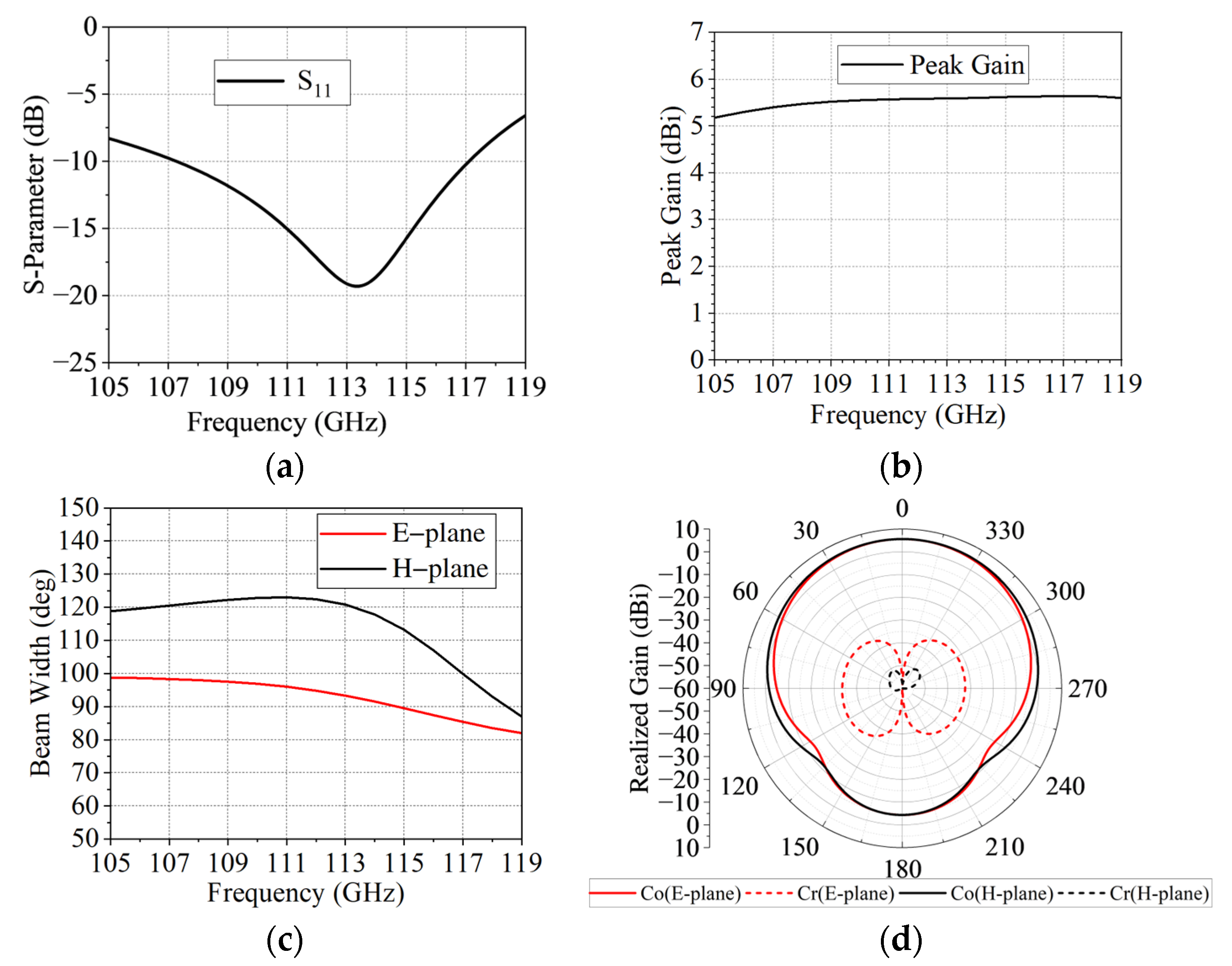
The element is simulated under radiation boundary conditions, and the simulation results are shown in Figure 2. As shown in Figure 2a, the simulated S11 of the element is less than −10 dB from 107 to 117 GHz. As shown in Figure 2b, the peak gain is stable at 5.4–5.64 dBi within the bandwidth. As shown in Figure 2c, the E-plane half-power beam width within the bandwidth is between 85.4 and 98.3°, and the H-plane half-power beam width is between 100 and 123°, showing a wide-beam characteristic. Figure 2d presents the radiation pattern at 112 GHz, with a normal gain of 5.58 dBi, and the half-power beam widths in the E-plane and H-plane are 94.8° and 122.4°, respectively. Additionally, the cross-polarization levels in both the E-plane and H-plane are below −40 dB.
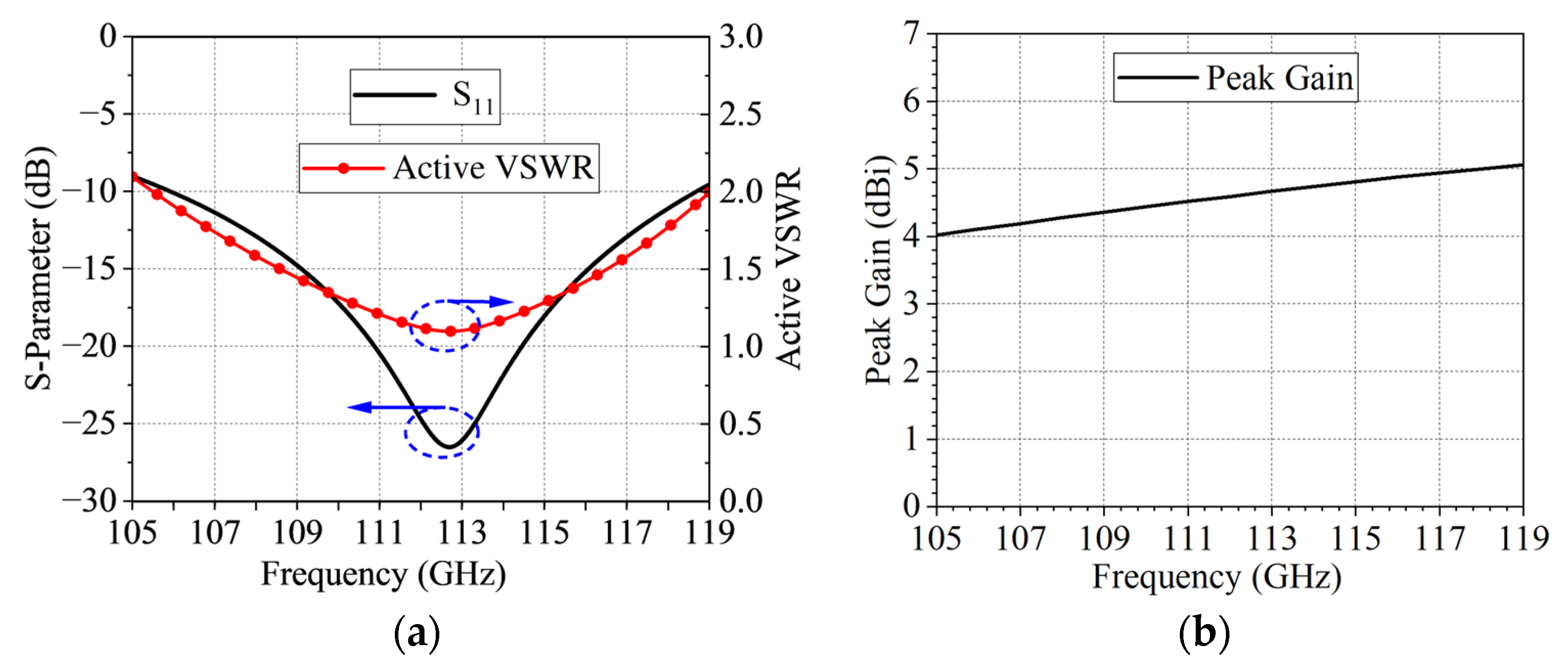
The proposed element will eventually be used for PAA design, so the performance under periodic boundary conditions also needs to be considered [30,31,32]. The simulation results of the element under periodic boundary conditions are shown in Figure 3. As shown in Figure 3a, the S11 bandwidth is 106–119 GHz, and the active VSWR is less than 2 within the range of 105.5–119 GHz. As shown in Figure 3b, the peak gain under periodic boundary conditions is stable at 4.1–5 dBi within the bandwidth.
As shown in the element simulation results, the element exhibits characteristics such as wideband, wide beam, stable gain, and low cross-polarization, meeting the basic requirements for the design of a wide-angle scanning PAA [33,34,35].

2.3. Parameters and Coupling Analysis

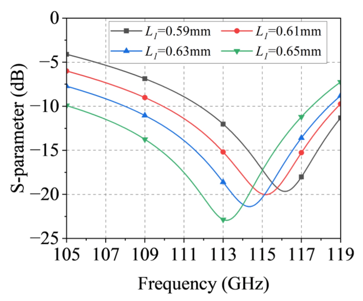
Like most half-wavelength antennas, the dimensions of the proposed element (Dx = Dy = 1.3 mm) are roughly half the wavelength of the center frequency. During the optimization of the proposed antenna element parameters, it was found that after tuning the bandwidth to the target frequency band, the bandwidth of the element can be further optimized by fine-tuning L1. Figure 4 shows the S11 curves corresponding to different L1, and it can be observed that the bandwidth is the widest when L1 is taken as 0.65 mm.
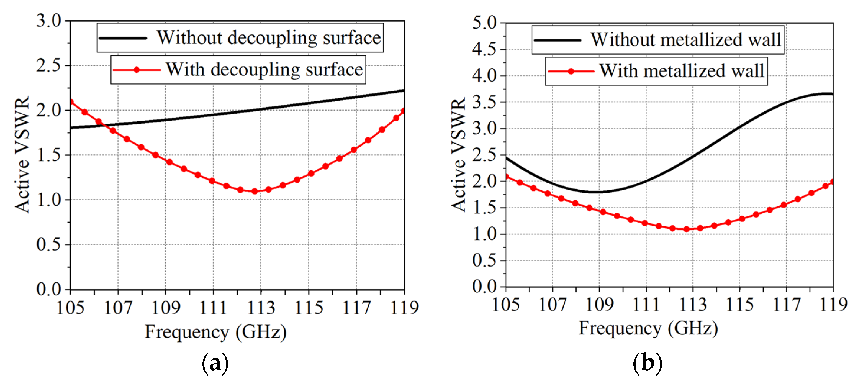
Existing research indicates that the active VSWR of PAAs is closely related to the coupling between elements, and excessive coupling between elements can lead to the deterioration of the active VSWR [24,29,36,37]. Therefore, to verify the decoupling effects of the decoupling surface and the metallized wall, simulations of the active VSWR with periodic boundaries are conducted. Simulations are performed on the active VSWR of periodic boundary elements with and without the decoupling surface to verify the decoupling effect of the decoupling surface. Simulations are also performed on the active VSWR of periodic boundary elements with and without the metallized wall to verify the decoupling effect of the metallized wall. As shown in Figure 5a, the simulation of the active VSWR with and without the decoupling surface in the periodic boundary indicates that the performance of the active VSWR with the decoupling surface is better than that without the decoupling surface, demonstrating that the decoupling surface achieves the decoupling effect. As shown in Figure 5b, the simulation of the active VSWR with and without the metallized wall in the periodic boundary indicates that the active VSWR with the metallized wall is far superior to that without the metallized wall, demonstrating that the metallized wall achieves a very good decoupling effect.
For a more intuitive comparison, Figure 6 provides the distribution of the surface currents of the ground at 112 GHz. Shown in Figure 6a is the surface current distribution of the proposed element ground. Shown in Figure 6b is the surface current distribution of the ground without the decoupling surface. Shown in Figure 6c is the surface current distribution of the ground without the metallized wall. Comparing Figure 6a,b, it can be found that the surface current at the edge of the ground with the decoupling surface is very small, indicating weak coupling between elements, while the surface current without the decoupling surface is larger, indicating stronger coupling between elements. Comparing Figure 6a,c, it can be found that the surface current at the edge of the ground with the metallized wall is very small, indicating weak coupling between elements, while the surface current without the metallized wall is very large, indicating very strong coupling between elements. By comparing Figure 6b,c, it can be found that the surface current of the ground without the decoupling surface is smaller than that without the metallized wall; thus, the decoupling effect of adding a metallized wall is more pronounced than that of adding a decoupling surface.
To further confirm the decoupling effect of the decoupling surface and metallized wall designed within the unit, Figure 7 provides the S-parameter simulation results of the 2 × 2 array. It can be seen from Figure 7 that within the bandwidth of 106.25–117.49 GHz, the worst-case port isolation is higher than 17.7 dB (i.e., S31 < −17.7 dB), and the port isolation is higher than 19 dB in most of the operating band.

3. The Performance of the 8 × 8 PAA

3.1. The PAA Configuration

An 8 × 8 planar PAA simulation model is established in CST2022 to verify the scanning performance of the proposed antenna. According to the PAA grating lobe suppression condition, G < λ/(1 + sinθmax), where G is the spacing between adjacent elements, λ is the wavelength, and θmax is the maximum scanning angle without grating lobes [37]. To ensure that there are no grating lobes during the wide-angle scanning process across the entire operating bandwidth, the element spacing is set to 1.3 mm (which is 0.516λ0 at 119 GHz). Consequently, the dimensions of the 8 × 8 planar PAA are 10.4 × 10.4 × 0.75 mm3. Shown in Figure 8 is the CST simulation model of the 8 × 8 planar PAA. We have commissioned Taizhou Wangling to conduct a cost estimation for the proposed 8 × 8 planar PAA. The quoted material cost for the dielectric substrate is RMB 10,000, and the processing fee is RMB 1700, making the total cost RMB 11,700.

3.2. The Simulated Scanning Performance

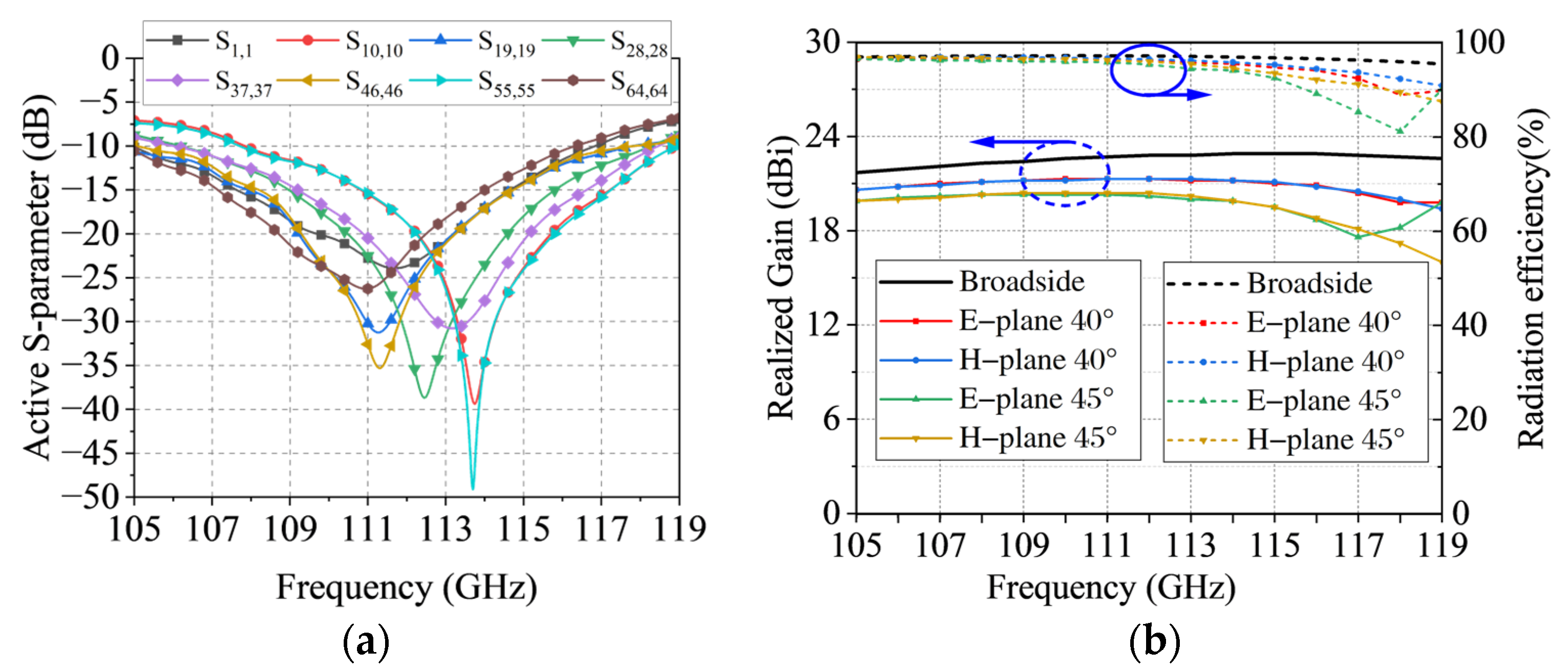
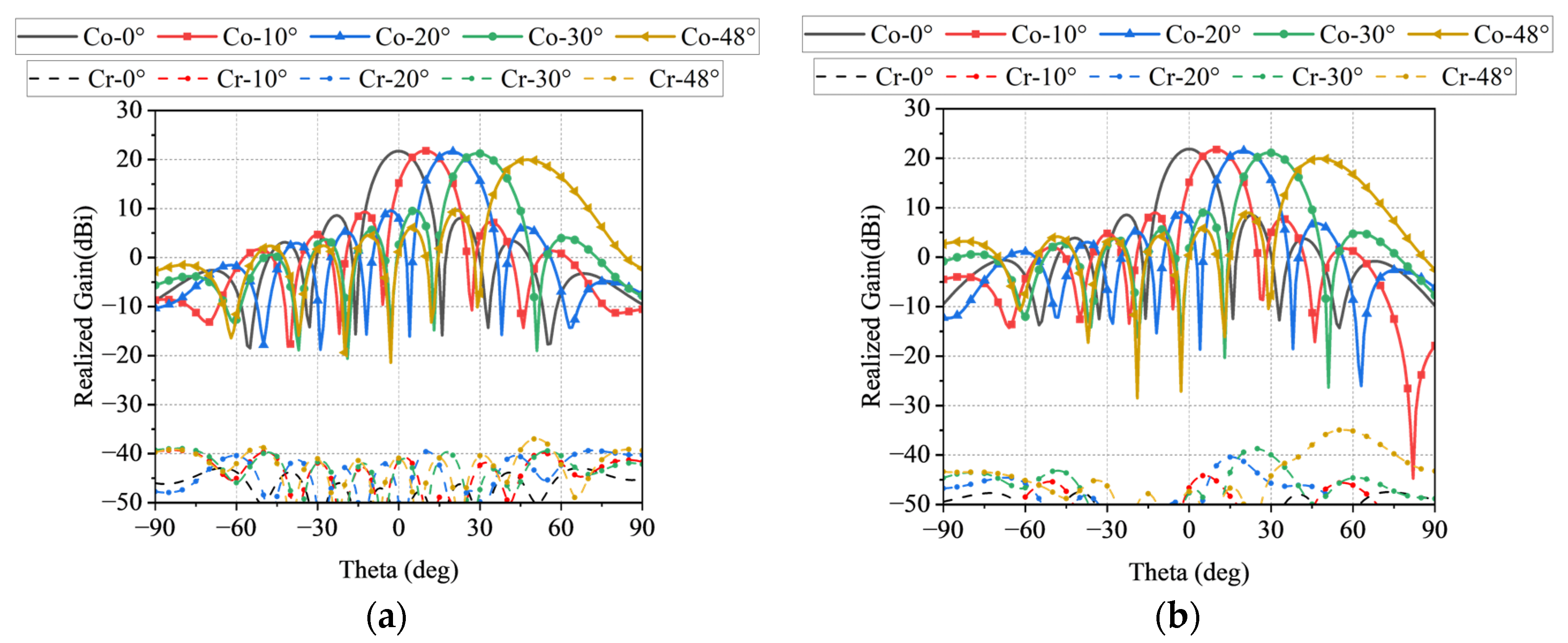
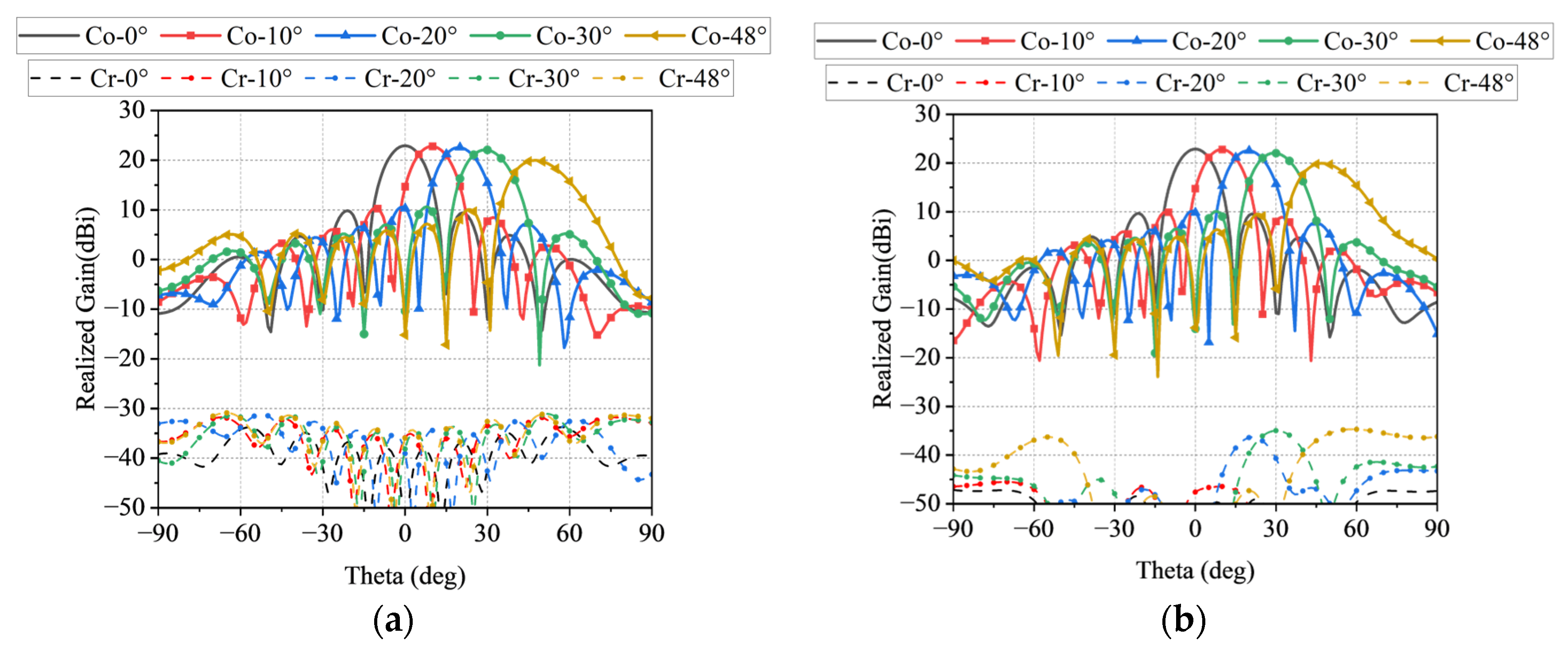
We simulated the PAA’s beam-scanning performance at integer frequency points within the 105–119 GHz band, and the simulation results are shown in Figure 9. Due to the large number of elements, Figure 9a only provides the active Sii of the most representative main diagonal elements, using the numbering of the main diagonal elements as shown in Figure 8b. As depicted in Figure 9b, with the gain variation within 3 dB, a 2-D wide-angle scanning of ±48° is achieved from 106 to 114 GHz. From 115 to 119 GHz, the scanning range reached ±40° on the E-plane and H-plane. Additionally, the normal peak gain is stably maintained at 21.9–22.8 dBi across the operating frequency band. Moreover, the normal radiation efficiency of the PAA is higher than 95% within the operating frequency band. The radiation efficiency is higher than 81% within the ±48° scanning range on the E-plane and higher than 87% on the H-plane. To make the beam-scanning performance of the PAA more intuitive, Figure 10, Figure 11 and Figure 12, respectively, provide the beam-scanning radiation pattern at three key frequency points of 106 GHz, 114 GHz, and 119 GHz.
As shown in Figure 10, which depicts the E-plane and H-plane radiation pattern at 106 GHz, the normal peak gain is 21.9 dBi. When scanning to 48° on the E-plane, the gain is 20.1 dBi. When scanning to 48° on the H-plane, the realized gain is 20 dBi, with a gain reduction of only 1.9 dB. Within the scanning range, the sidelobe level (SLL) on both the E-plane and H-plane is below −10 dB, and the cross-polarization is below −35 dB.
Figure 11 shows the E-plane and H-plane scanning radiation pattern at 114 GHz, with a normal peak gain of 22.8 dBi. When scanning to 48° on both the E-plane and H-plane, the realized gain is 19.9 dBi, with a gain reduction of only 2.9 dB. Within the scanning range, the SLL on both the E-plane and H-plane is below −10 dB, and the cross-polarization is below −30 dB.
Figure 12 illustrates the E-plane and H-plane scanning radiation pattern at 119 GHz, with a normal peak gain of 22.5 dBi. When scanning to 40° on the E-plane, the gain is 19.8 dBi, with a gain reduction of 2.7 dB. When scanning to 40° on the H-plane, the gain is 20 dBi, with a gain reduction of 2.5 dB. Within the scanning range, the SLL on both the E-plane and H-plane is below −10 dB, and the cross-polarization is below −29 dB.

4. Discussion

Table 2 presents a comprehensive comparison between the proposed THz PAA and other works. Compared to the THz PAAs proposed in [20,21,22,23], the advantages of the PAA proposed in this paper are mainly reflected in 2-D beam scanning and a wider scanning range. Compared with [20,21,23], which achieve 1-D beam scanning with a maximum scanning angle of 90°, we can achieve 2-D beam scanning of more than 96° within the frequency range of 106–114 GHz. In contrast, ref. [22] can achieve 2-D beam scanning within a 60° range, while we can achieve 2-D beam scanning of more than 80° across the entire operating frequency band.

5. Conclusions

This paper introduces a novel THz band gain-stable 2-D wide-angle scanning PAA. According to the 8 × 8 PAA’s simulated results, a 2-D wide-angle scanning of ±48° was achieved from 106 to 114 GHz, while in the 115–119 GHz range, the scanning range reached ±40° on the E-plane and H-plane. Additionally, the normal peak gain was stably maintained at 21.9–22.8 dBi across the operating frequency band. Compared with other works, the advantages of this work are mainly reflected in 2-D beam scanning and a wider scanning range. Due to its stable gain and 2-D wide-angle scanning performance, the proposed PAA has a broad application prospect in THz wireless-communication equipment. The next step will involve designing a feeding network for the proposed PAA, then seeking available beam control chips, and, finally, fabricating a prototype to measure the beam-scanning performance in order to accelerate the application of the proposed PAA in THz wireless communication.

Author Contributions

Methodology, W.X. and Y.Z.; Software, B.X.; Resources, W.X.; Writing—original draft, B.X.; Writing—review and editing, Y.Z. All authors have read and agreed to the published version of the manuscript.

Funding

This research received no external funding.

Institutional Review Board Statement

Not applicable.

Informed Consent Statement

Not applicable.

Data Availability Statement

The datasets created and analyzed during this study are available from the corresponding author upon reasonable request.

Conflicts of Interest

The authors declare no conflicts of interest.

References

  1. Rappaport, T.S.; Xing, Y.; Kanhere, O.; Ju, S.; Madanayake, A.; Mandal, S.; Alkhateeb, A.; Trichopoulos, G.C. Wireless Communications and Applications above 100 GHz: Opportunities and Challenges for 6G and Beyond. IEEE Access. 2019, 7, 78729–78757. [Google Scholar] [CrossRef]
  2. Zhang, J.; Kang, K.; Huang, Y.; Shafi, M.; Molisch, A.F. Millimeter and THz Wave for 5G and Beyond. China Commun. 2019, 16, iii–vi. [Google Scholar]
  3. Okada, K. Sub-THz CMOS Phased-Array Transceiver Design for 6G. In Proceedings of the 2024 IEEE International Symposium on Circuits and Systems (ISCAS), Singapore, 19–22 May 2024; pp. 1–4. [Google Scholar]
  4. Okada, K. Millimeter-Wave/THz CMOS Phased-Array Transceiver for 5G and Beyond. In Proceedings of the 2022 IEEE International Symposium on Radio-Frequency Integration Technology (RFIT), Busan, Republic of Korea, 29–31 August 2022; pp. 219–221. [Google Scholar]
  5. Okada, K. CMOS THz Phased-Array Transceivers for beyond 5G. In Proceedings of the 2021 IEEE International Symposium on Radio-Frequency Integration Technology (RFIT), Hualien, Taiwan, 25–27 August 2021; pp. 1–2. [Google Scholar]
  6. Jiang, M.; Chen, Z.N.; Zhang, Y.; Hong, W.; Xuan, X. Metamaterial-Based Thin Planar Lens Antenna for Spatial Beamforming and Multibeam Massive MIMO. IEEE Trans. Antennas Propag. 2017, 65, 464–472. [Google Scholar] [CrossRef]
  7. Plaza, E.G.; Costa, J.R.; Fernandes, C.A.; León, G.; Loredo, S.; Las-Heras, F. A Multibeam Antenna for Imaging Based on Planar Lenses. In Proceedings of the 2015 9th European Conference on Antennas and Propagation (EuCAP), Lisbon, Portugal, 13–17 April 2015; pp. 1–5. [Google Scholar]
  8. Tsai, Z.-C.; Chou, H.-T. Waveguide-Type Transmitarray Antennas with a Concave Surface Profile Analogous to Rotman Lens for Spatial Feeding to Radiate Collinear Multi-Beams. In Proceedings of the 2017 International Symposium on Antennas and Propagation (ISAP), Phuket, Thailand, 30 October–2 November 2017; pp. 1–2. [Google Scholar]
  9. Beccaria, M.; Massaccesi, A.; Pirinoli, P.; Manh, L.H. Multibeam Transmitarrays for 5G Antenna Systems. In Proceedings of the 2018 IEEE Seventh International Conference on Communications and Electronics (ICCE), Hue, Vietnam, 18–20 July 2018; pp. 217–221. [Google Scholar]
  10. Nayeri, P.; Yang, F.; Elsherbeni, A.Z. Bifocal Design and Aperture Phase Optimizations of Reflectarray Antennas for Wide-Angle Beam Scanning Performance. IEEE Trans. Antennas Propag. 2013, 61, 4588–4597. [Google Scholar] [CrossRef]
  11. Cui, Y.; Bahr, R.; Nauroze, S.A.; Cheng, T.; Almoneef, T.S.; Tentzeris, M.M. 3D Printed “Kirigami”-Inspired Deployable Bi-Focal Beam-Scanning Dielectric Reflectarray Antenna for Mm-Wave Applications. IEEE Trans. Antennas Propag. 2022, 70, 7683–7690. [Google Scholar] [CrossRef]
  12. Yang, G.; Zhang, S. Dual-Polarized Wide-Angle Scanning Phased Array Antenna for 5G Communication Systems. IEEE Trans. Antennas Propag. 2022, 70, 7427–7438. [Google Scholar] [CrossRef]
  13. Jalili, H.; Momeni, O. Scalable Wideband and Wide-Angle Beam Steering Mm-Wave/THz Radiator and Phased Arrays in Silicon. In Proceedings of the 2018 Asia-Pacific Microwave Conference (APMC), Kyoto, Japan, 6–9 November 2018; pp. 1157–1159. [Google Scholar]
  14. Tousi, Y.; Afshari, E. A Scalable THz 2D Phased Array with +17dBm of EIRP at 338GHz in 65nm Bulk CMOS. In Proceedings of the 2014 IEEE International Solid-State Circuits Conference Digest of Technical Papers (ISSCC), San Francisco, CA, USA, 9–13 February 2014; pp. 258–259. [Google Scholar]
  15. Valdes-Garcia, A.; Floyd, B.; Nicolson, S.T.; Lai, J.-W.; Natarajan, A.; Chen, P.-Y.; Reynolds, S.K.; Zhan, J.-H.C.; Kam, D.G.; Liu, D. A Fully Integrated 16-Element Phased-Array Transmitter in SiGe BiCMOS for 60-GHz Communications. IEEE J. Solid-State Circuits 2010, 45, 2757–2773. [Google Scholar] [CrossRef]
  16. Fu, X.; Yang, F.; Liu, C.; Wu, X.; Cui, T.J. Terahertz Beam Steering Technologies: From Phased Arrays to Field-programmable Metasurfaces. Adv. Opt. Mater. 2020, 8, 1900628. [Google Scholar] [CrossRef]
  17. Mangiavillano, C.; Zachl, G.; Hüttner, R.; Wagner, T.; Stelzer, A.; Pretl, H. A 0.32-THz 4-Transmitter Phased Array Using Chiplets in 130-Nm SiGe BiCMOS. In Proceedings of the 2023 Asia-Pacific Microwave Conference (APMC), Taipei, Taiwan, 5–8 December 2023; pp. 757–759. [Google Scholar]
  18. Yang, L.-Y.O.; Wu, W.-H.; Tsai, B. EIRP Optimization of a Phased Array with Mutual Coupling for THz Applications. In Proceedings of the 2022 IEEE Conference on Antenna Measurements and Applications (CAMA), Guangzhou, China, 14–17 December 2022; pp. 1–3. [Google Scholar]
  19. Prather, D.W.; Murakowski, J.A.; Schuetz, C.; Shi, S.; Schneider, G.J.; Harrity, C.; Aranda, Z.D.; Marinucci, D.; Hallak, A.; Zablocki, M.; et al. Millimeter-Wave and Sub-THz Phased-Array Imaging Systems Based on Electro-Optic up-Conversion and Optical Beamforming. IEEE J. Select. Top. Quantum Electron. 2023, 29, 8501014. [Google Scholar] [CrossRef]
  20. Li, P.; Shi, Y.; Deng, Y.; Liu, L. Computational Analysis of a 200 GHz Phased Array Using Lens-Coupled Annular-Slot Antennas. Appl. Sci. 2022, 12, 1407. [Google Scholar] [CrossRef]
  21. Guo, K.; Reynaert, P. A 0.59THz Beam-Steerable Coherent Radiator Array with 1mW Radiated Power and 24.1dBm EIRP in 40nm CMOS. In Proceedings of the 2020 IEEE International Solid- State Circuits Conference—(ISSCC), San Francisco, CA, USA, 16–20 February 2020; pp. 442–444. [Google Scholar]
  22. Saeidi, H.; Venkatesh, S.; Chappidi, C.R.; Sharma, T.; Zhu, C.; Sengupta, K. A 4×4 Distributed Multi-Layer Oscillator Network for Harmonic Injection and THz Beamforming with 14dBm EIRP at 416GHz in a Lensless 65nm CMOS IC. In Proceedings of the 2020 IEEE International Solid- State Circuits Conference—(ISSCC), San Francisco, CA, USA, 16–20 February 2020; pp. 256–258. [Google Scholar]
  23. Gao, L.; Chan, C.H. A 0.64-to-0.69THz Beam-Steerable Coherent Source with 9.1dBm Radiated Power and 30.8dBm Lensless EIRP in 65nm CMOS. In Proceedings of the 2023 IEEE International Solid- State Circuits Conference (ISSCC), San Francisco, CA, USA, 19–23 February 2023; pp. 362–364. [Google Scholar]
  24. Wu, K.-L.; Wei, C.; Mei, X.; Zhang, Z.-Y. Array-Antenna Decoupling Surface. IEEE Trans. Antennas Propag. 2017, 65, 6728–6738. [Google Scholar] [CrossRef]
  25. Lin, L.-X.; Tu, Z.-H.; Zhu, H. Isolation Enhancement in Millimeter-Wave MIMO Array Base on Array-Antenna Decoupling Surface. In Proceedings of the 2022 IEEE MTT-S International Microwave Workshop Series on Advanced Materials and Processes for RF and THz Applications (IMWS-AMP), Guangzhou, China, 13–15 November 2022; pp. 1–3. [Google Scholar]
  26. Wang, Z.; Tu, Z.-H.; Yuan, Z.; Chen, F.-C. Decoupling and Wide-Angle Scanning Design of a Millimeter-Wave Phased Array Using Square-Ring Metasurface. IEEE Antennas Wirel. Propag. Lett. 2023, 22, 1828–1832. [Google Scholar] [CrossRef]
  27. Li, D.F.; Zhong, Y.C.; Liu, Y. Planar Low-Profile 2-D Wide-Angle Scanning Phased Array in X-Band Based on SIW. In Proceedings of the 2022 IEEE 10th Asia-Pacific Conference on Antennas and Propagation (APCAP), Xiamen, China, 4–7 November 2022; pp. 1–2. [Google Scholar]
  28. Wang, Z.; Hu, Y.; Xiang, L.; Xu, J.; Hong, W. A Wideband High-Gain Planar Monopulse Array Antenna for Ka-Band Radar Applications. IEEE Trans. Antennas Propag. 2023, 71, 8739–8752. [Google Scholar] [CrossRef]
  29. Puskely, J.; Mikulasek, T.; Aslan, Y.; Roederer, A.; Yarovoy, A. 5G SIW-Based Phased Antenna Array with Cosecant-Squared Shaped Pattern. IEEE Trans. Antennas Propag. 2022, 70, 250–259. [Google Scholar] [CrossRef]
  30. Ding, Y.R.; Cheng, Y.J.; Sun, J.X.; Wang, L.; Li, T.J. Dual-Band Shared-Aperture Two-Dimensional Phased Array Antenna with Wide Bandwidth of 25.0% and 11.4% at Ku- and Ka-Band. IEEE Trans. Antennas Propag. 2022, 70, 7468–7477. [Google Scholar] [CrossRef]
  31. Song, A.H.; Cheng, Y.J. Shared-Aperture Dual-Polarized Ku-Band and Single-Polarized Ka-Band Phased Array Antenna with Scanning Coverage Enhancement. IEEE Trans. Antennas Propag. 2022, 70, 10426–10435. [Google Scholar] [CrossRef]
  32. Lu, S.; Qu, S.-W.; Li, P.-F. Low-Profile Ku-/Ka-Band Shared-Aperture Phased Array. IEEE Trans. Antennas Propag. 2024, 72, 300–309. [Google Scholar] [CrossRef]
  33. Jiang, W.; Liao, S.; Che, W.; Xue, Q. Millimeter-Wave Wideband ±45° Dual-Polarized Phased Array Antenna Based on Compact Wideband Widebeam Dipole Element Antenna. IEEE Antennas Wirel. Propag. Lett. 2023, 22, 1813–1817. [Google Scholar] [CrossRef]
  34. Tang, Z.; Dong, Y. A Ka-Band Antenna Array Based on Wide-Beamwidth Magnetoelectric Dipole. IEEE Antennas Wirel. Propag. Lett. 2022, 21, 501–505. [Google Scholar] [CrossRef]
  35. Yang, G.; Li, J.; Wei, D.; Xu, R. Study on Wide-Angle Scanning Linear Phased Array Antenna. IEEE Trans. Antennas Propag. 2018, 66, 450–455. [Google Scholar] [CrossRef]
  36. Gu, L.; Liao, S.; Che, W. Novel Coupling Cancellation Method by Loading Planar Path for Wideband High-Isolation Wide-Scanning Millimeter-Wave Phased Array. IEEE Trans. Antennas Propag. 2022, 70, 10520–10530. [Google Scholar] [CrossRef]
  37. Li, J.; Zhu, Y.; Hu, Y.; Hong, W. A Miniaturized Dual-Polarized Active Phased Array Antenna for 5G Millimeter-Wave Applications. IEEE Antennas Wirel. Propag. Lett. 2024, 23, 618–622. [Google Scholar] [CrossRef]
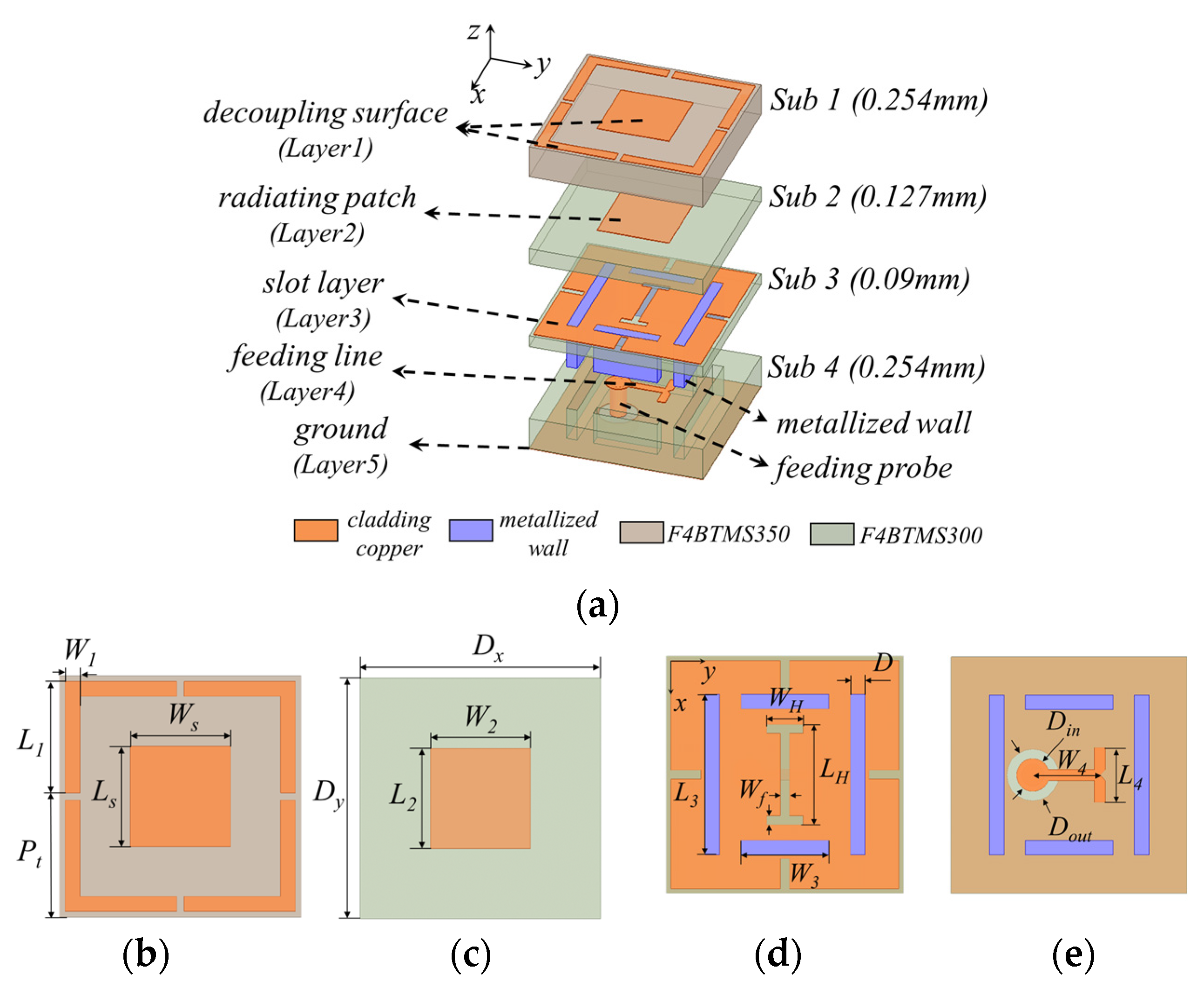
Figure 1. (a) Three-dimensional exploded view of the element. Top view of (b) decoupling surface, (c) radiating patch, (d) slot layer, and (e) feeding line.
Applsci 14 08618 g001
Figure 2. The radiation boundary simulation results of the element. (a) S-parameter. (b) Peak gain. (c) Beam width. (d) Radiation pattern at 112 GHz.
Applsci 14 08618 g002
Figure 3. The periodic boundary simulation results of the element. (a) S-parameter and VSWR. (b) Peak gain.
Applsci 14 08618 g003
Figure 4. The S11 curves corresponding to different L1.
Applsci 14 08618 g004
Figure 5. The periodic boundary simulation active VSWR. (a) With/without decoupling surface. (b) With/without metallized wall.
Applsci 14 08618 g005
Figure 6. The simulation surface current distribution of the ground at 112 GHz. (a) The proposed element. (b) Without decoupling surface. (c) Without metallized wall.
Applsci 14 08618 g006
Figure 7. The S-parameter simulation results of the 2 × 2 array.
Applsci 14 08618 g007
Figure 8. The CST simulation model of the 8 × 8 planar PAA. (a) Top view. (b) Bottom view. (c) Three-dimensional perspective view.
Applsci 14 08618 g008
Figure 9. The simulation results. (a) Active S-parameter. (b) Realized gains and radiation efficiencies when scanning to different angles.
Applsci 14 08618 g009
Figure 10. The scanning patterns of the 8 × 8 PAA at 106 GHz. (a) E-plane; (b) H-plane.
Applsci 14 08618 g010
Figure 11. The scanning patterns of the 8 × 8 PAA at 114 GHz. (a) E-plane; (b) H-plane.
Applsci 14 08618 g011
Figure 12. The scanning patterns of the 8 × 8 PAA at 119 GHz. (a) E-plane; (b) H-plane.
Applsci 14 08618 g012
Table 1. The element geometrical parameters (unit: mm).
ParameterValueParameterValue
L10.65W10.08
L20.54W20.54
L30.88W30.48
L40.30W40.37
Ls0.52Ws0.52
LH0.55WH0.20
Dx1.30Dy1.30
Din0.18Dout0.29
Pt0.72Wf0.05
Table 2. Comparison between the proposed THz PAA and other works.
ReferenceFrequency (GHz)Array SizeScanning DimensionBeam Scanning (°)Fabrication Technology
[20]2001 × 51-D62N/A
[21]586.76 × 61-D3040 nm CMOS
[22]4164 × 42-D60/6065 nm CMOS
[23]67512 × 121-D9065 nm CMOS
This work1068 × 82-D96/96N/A
11496/96
11980/80
Disclaimer/Publisher’s Note: The statements, opinions and data contained in all publications are solely those of the individual author(s) and contributor(s) and not of MDPI and/or the editor(s). MDPI and/or the editor(s) disclaim responsibility for any injury to people or property resulting from any ideas, methods, instructions or products referred to in the content.