Improving the Performance of a Salt Production Plant by Using Nanofiltration as a Pretreatment
Abstract
:1. Introduction
2. Materials and Methods
2.1. Pilot-Scale NF
2.2. Modelling of Large-Scale NF Pretreatment
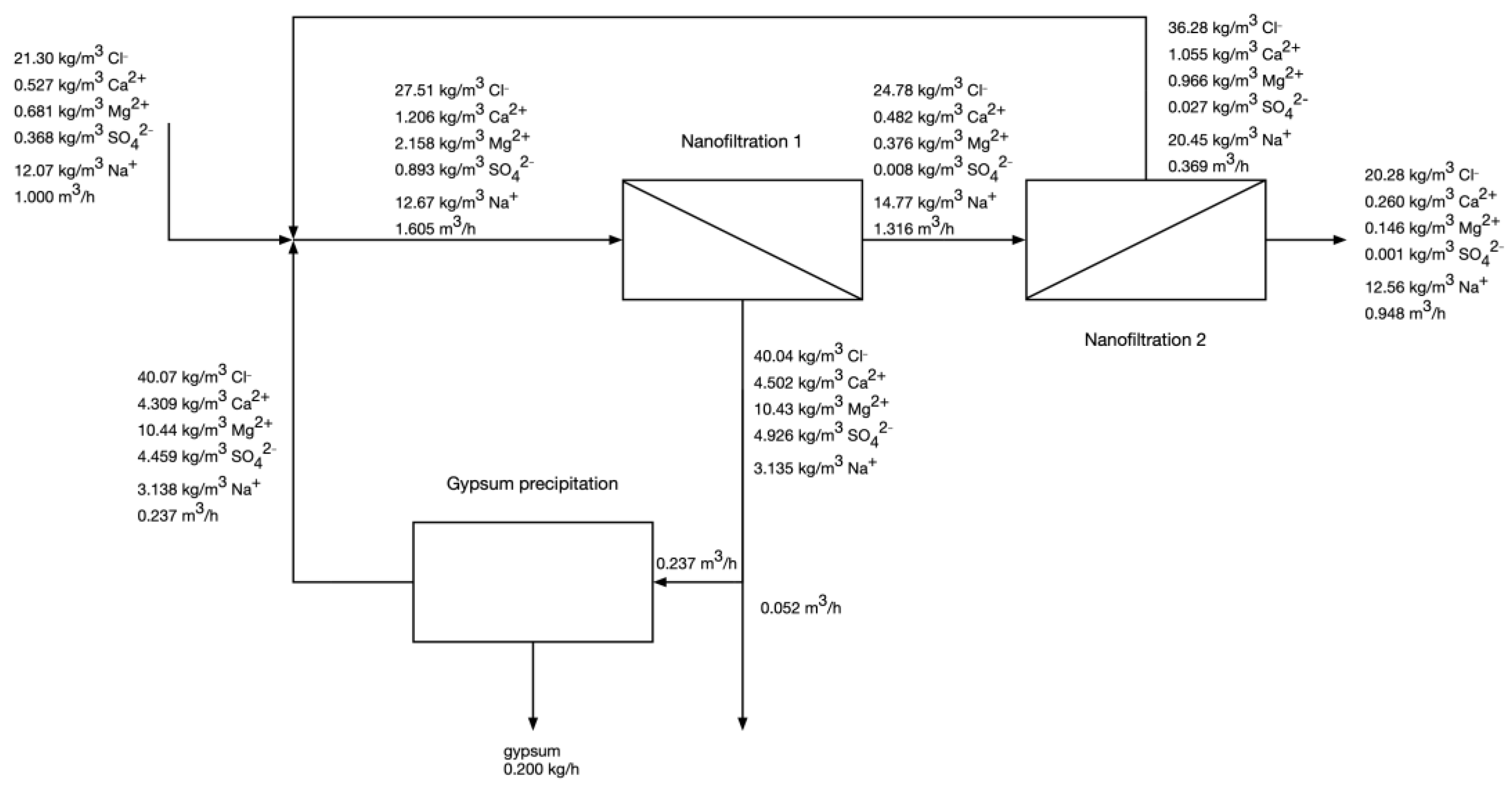
- The feed flow rate is 1 m3/h. In practice, scaling up the NF capacity would increase the mass of precipitated gypsum and the volumetric flow rates of the Mg-rich stream, and the NF-NF permeate, but it should not influence the ionic composition of the streams.
- The feed water has the average composition of “Budryk” coal mine brackish water—21.3 kg/m3 as Cl−, 0.527 kg/m3 as Ca2+, 0.681 kg/m3 as Mg2+, 0.368 kg/m3 as SO42−, 12.07 kg/m3 as Na+.
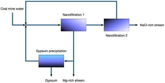
- The entire permeate from the 1st pass of NF is fed to the 2nd pass of NF.
- A major portion of retentate from the 1st pass of NF is used to precipitate gypsum. The unused portion of 1st pass retentate (Mg-rich stream) is discharged and treated as waste.
- The rejection coefficients of ions for the 1st pass were as follows: Cl- 10%, Ca2+ 60%, Mg2+ 82.8%, SO42− 99.1%. These were the values obtained experimentally during the pilot phase of the research at a feed flow rate of 265 L/h, permeate recovery of 82% and hydraulic pressure of 15.5 bar.
- The rejection coefficients of ions for the 2nd pass were as follows: Cl- 18.1%, Ca2+ 46.2%, Mg2+ 61.1%, SO42− 92.6%. These values were obtained in bench-scale experiments on the model solutions resembling the NF1 permeate - a laboratory-scale dead-end Sterlitech® HP 4750 Stirred Cell stainless steel membrane module equipped with cooling jacket was used. The commercial flat-sheet Trisep TS40 NF membranes were cut into circular-shaped pieces, with an effective membrane area of 14.6 cm2, and tested under a pressure of 30 bar.
- The required pressure drop in each of the NF passes was calculated using Equation (1), where TDS denotes the salinity (of feed, permeate, or retentate) in kg/m3. See [13] for the formula derivation.
- The energy consumption in each of the NF passes was calculated using Equation (2), where Y denotes the permeate recovery, and P denotes the required pressure drop, as calculated by Equation (1). See [13] for the formula derivation.
- Gypsum can be precipitated down to the saturation level of 138% - this was confirmed experimentally during the pilot stage of the results. Gypsum seeding is used, with no additional chemicals. It was assumed that this unit operation has no energy consumption.
- Assume some permeate recovery in NF1 and NF2.
- For step one, assume no recycle—the NF1 feed water is the raw coal mine water.
- Calculate the composition and flow rates of all streams in the two-stage NF using respective mass balances and ionic rejection coefficients.
- Calculate the amount of obtained gypsum assuming final saturation after precipitation is 138%.
- Using appropriate mass balance equations, calculate the new composition of NF1 feed, assuming the post-precipitation stream, the NF2 retentate, and the coal mine water are mixed.
- Compare the differences in ion concentrations and flow rate of the new NF1 feed with the NF1 feed used in previous step—if any of those differences is higher than 0.1%, go to step 3.
- If the calculation has converged (i.e. all errors < 0.1%), repeat steps 3–6 with increased value of NF1 and NF2 recovery.
- Keep increasing the values of NF1 and NF2 recovery and repeating the calculations as long as steps 3-6 can converge to a physically possible solution (e.g. positive value of precipitated gypsum, saturation of NF retentate < 400%, positive concentration of each of the ion etc.).
- After the maximum realistic values of NF1 and NF2 recovery have been obtained, use Equation (1) to calculate the required pressures.
2.3. Modelling of RO-Evaporator-Crystallizer Technology
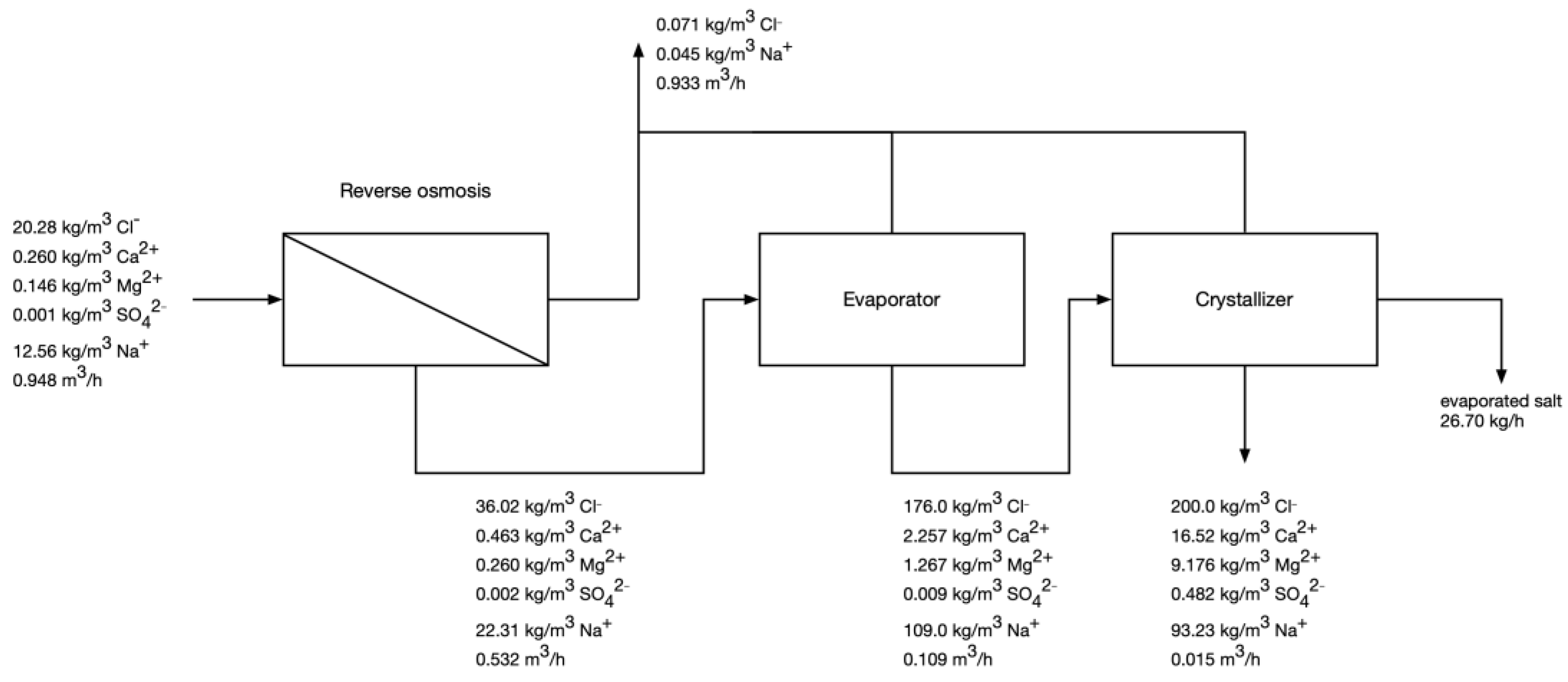
- Check if the TDS of feed water is higher than 45 kg/m3; if yes—go to step 6.
- Assume RO recovery of 0.2%.
- Calculate the composition of RO permeate and retentate using mass balances, RO recovery, and assumed rejection coefficients [13].
- If Cl− content is below 36 kg/m3, increase the RO recovery by 0.2% and go back to step 3.
- Calculate the required RO pressure and energy consumption [13].
- Using mass balance equations, calculate the composition of the process streams in the evaporator step, assuming the final Cl- concentration in concentrate as 176 kg/m3 [13].
- Knowing the amount of water that needs to be evaporated, calculate the energy consumption in the evaporator.
- Minimize the error function of the crystallizer using the mass balance equations. The amount of evaporated water, crystallized salt and gypsum are the independent variables, whereas the maximum chloride concentration in the post-crystallization, the value of gypsum solubility product, and the bivalent cations as their respective chlorides in the post-crystallization lyes are the boundary conditions.
3. Results
3.1. Pilot-Scale
3.2. Modelling of Two-Pass NF with Intermediate Gypsum Precipitation
3.3. Modelling of RO-Evaporator-Crystallizer System
3.3.1. Current Dębieńsko Operation
3.3.2. Projected Operation after NF Pretreatment
4. Discussion
5. Conclusions
- -
- it can decrease the energy consumption by 21%, which is a positive outcome from both the economic point of view (decrease in the operating costs for the salt production plant) and from the environmental point of view (less electric energy consumption in a country where the energy grid is largely based on black coal),
- -
- it can decrease the volume of highly saline post-crystallization lyes by 66%, which makes them easier and less water-consuming for safe discharge into the environment,
- -
- it can increase salt recovery from 58.8% to 76.1%, which would help the company increase its production and decrease the amount of salt that ends up discharged to the surface waters,
- -
- it can generate a separate Mg-rich waste stream, which can be used for magnesium hydroxide recovery—this could create a new revenue stream for the coal mines and could help in transitioning from a linear to more circular economy.
Supplementary Materials
Author Contributions
Funding
Institutional Review Board Statement
Informed Consent Statement
Data Availability Statement
Conflicts of Interest
Abbreviations
| ED | electrodialysis |
| JSW | Jastrzębska Spółka Węglowe |
| NF | nanofiltration |
| PGWiR | Przedsiębiorstwo Gospodarki Wodnej i Rekultywacji |
| RO | reverse osmosis |
| SDI | silt density index |
| ZLD | zero liquid discharge |
References
- Drioli, E.; Criscuoli, A.; Curcio, E. Integrated membrane operations for seawater desalination. Desalination 2002, 147, 77–81. [Google Scholar] [CrossRef]
- Macedonio, F.; Curcio, E.; Drioli, E. Integrated membrane systems for seawater desalination: Energetic and exergetic analysis, economic evaluation, experimental study. Desalination 2007, 203, 260–276. [Google Scholar] [CrossRef]
- Davis, T.A. Production of Purified Water and High Value Chemicals from Salt Water. US Patent 2004055955, 1 August 2003. [Google Scholar]
- Wallace, P.S. Membrane and Electrodialysis Based Seawater Desalination with Salt, Boron and Gypsum Recovery. US Patent 8999171, 18 July 2011. [Google Scholar]
- Raman, A. Process and System for Producing Sodium Chloride Brine. Patent Application WO2013023249, 16 August 2012. [Google Scholar]
- Tanaka, Y.; Ehara, R.; Itoi, S.; Goto, T. Ion-exchange membrane electrodialytic salt production using brine discharged from a reverse osmosis seawater desalination plant. J. Membr. Sci. 2003, 222, 71–86. [Google Scholar] [CrossRef]
- Mitko, K.; Turek, M.; Jaroszek, H.; Bernacka, E.; Sambor, M.; Skóra, P.; Dydo, P. Pilot studies on circular economy solution for the coal mining sector. Water Res. Ind. 2021, 26, 100161. [Google Scholar] [CrossRef]
- Piecha, J.; Klimek, R. Desalination Plant at the Dębieńsko mine-waste-free disposal of saline mine waters. Wiad. Gór. 1998, 9, 379–384. [Google Scholar]
- Tsalidis, G.A.; Panteleaki Tourkodimitri, K.; Mitko, K.; Gzyl, G.; Skalny, A.; Posada, J.A.; Xevgenos, D. Assessing the environmental performance of a novel coal mine brine treatment technique: A case in Poland. J. Clean. Prod. 2022, 358, 131973. [Google Scholar] [CrossRef]
- Turek, M.; Laskowska, E.; Mitko, K. Mixing Element in Spacers for Membrane Modules. Patent PL236732, 23 November 2018. [Google Scholar]
- Turek, M.; Laskowska, E.; Mitko, K.; Kijański, M.; Chorążewska, M.; Miller-Turek, B. Spacer, in Prticular for Membrane Modules. Patent PL238442, 23 November 2018. [Google Scholar]
- Turek, M.; Laskowska, E.; Mitko, K.; Kijański, M.; Chorążewska, M.; Miller-Turek, B. Spacer with Mixing Elements, Particularly for Membrane Modules. Patent Application WO2020085925, 21 November 2019. [Google Scholar]
- Turek, M.; Laskowska, E.; Mitko, K.; Chorążewska, M.; Dydo, P.; Piotrowski, K.; Jakóbik-Kolon, A. Application of nanofiltration and electrodialysis for improved performance of a salt production plant. Desalin. Water Treat. 2017, 64, 244–250. [Google Scholar]
- Turek, M.; Laskowska, E.; Mitko, K.; Jakóbik-Kolon, A. Method of Saline Water Pretreatment for Its Desalination and Concentration and a Hybrid Membrane System for Implementing the Method. Patent Application P.426379, 19 July 2018. [Google Scholar]
- Micari, M.; Cipollina, A.; Tamburini, A.; Moser, M.; Bertsch, V.; Micale, G. Techno-economic analysis of integrated processes for the treatment and valorisation of neutral coal mine effluents. J. Clean. Prod. 2020, 270, 122472. [Google Scholar] [CrossRef]
- Vassallo, F.; La Corte, D.; Cipollina, A.; Tamburini, A.; Micale, G. High purity recovery of magnesium and calcium hydroxides from waste brines. Chem. Eng. Trans. 2021, 86, 931–936. [Google Scholar]
- Vassallo, F.; Morgante, C.; Battaglia, G.; La Corte, D.; Micari, M.; Cipollina, A.; Tamburini, A. A simulation tool for ion exchange membrane crystallization of magnesium hydroxide from waste brine. Chem. Eng. Res. Design. 2021, 173, 193–205. [Google Scholar] [CrossRef]
- Vassallo, F.; La Corte, D.; Cancilla, N.; Tamburini, A.; Bevacqua, M.; Cipollina, A.; Micale, G. A pilot-plant for the selective recovery of magnesium and calcium from waste brines. Desalination 2021, 517, 115231. [Google Scholar] [CrossRef]
- Morgante, C.; Vassallo, F.; Battaglia, G.; Cipollina, A.; Vicari, F.; Tamburini, A.; Micale, G. Influence of Operational Strategies for the Recovery of Magnesium Hydroxide from Brines at a Pilot Scale. Ind. Eng. Chem. Res. 2022, 61, 15355–15368. [Google Scholar] [CrossRef] [PubMed]


| Recovery [%] | Linear Flow Rate [cm/s] | Rejection [%] | ||||||
|---|---|---|---|---|---|---|---|---|
| Start | End | Na+ | Cl− | SO42− | K+ | Mg2+ | Ca2+ | |
| 78.2% | 11.33 | 5.38 | 9.5% | 17.8% | >97.3% | 9.3% | 90.6% | 72.0% |
| 78.2% | 11.33 | 5.38 | 8.8% | 17.5% | >97.3% | 9.9% | 90.7% | 71.8% |
| 80.9% | 19.66 | 5.29 | 6.9% | 15.6% | >97.2% | 10.1% | 90.3% | 71.1% |
| 80.2% | 20.66 | 5.34 | 7.5% | 15.7% | >97.2% | 8.8% | 89.4% | 69.3% |
| 79.1% | 20.29 | 5.61 | 8.2% | 17.1% | >97.1% | 10.6% | 90.0% | 70.4% |
| 79.5% | 20.86 | 5.48 | 9.0% | 16.7% | >97.1% | 9.2% | 89.1% | 68.4% |
| 81.5% | 6.45 | 2.60 | 4.3% | 11.7% | >97.2% | 4.6% | 83.2% | 56.2% |
| 86.0% | 20.85 | 3.40 | 8.3% | 15.8% | >97.2% | 8.4% | 85.8% | 62.5% |
| 82.1% | 18.11 | 3.70 | 7.2% | 16.1% | >97.1% | 7.1% | 86.2% | 64.4% |
| 87.1% | 7.89 | 2.21 | 3.5% | 8.4% | >99.4% | 6.4% | 86.3% | 62.4% |
| 88.2% | 12.37 | 1.97 | 4.5% | 6.5% | 99.4% | 7.8% | 85.7% | 61.5% |
| 84.7% | 6.86 | 2.28 | 3.4% | 10.0% | >99.1% | 6.6% | 82.8% | 60.0% |
| 90.8% | 10.04 | 2.01 | 6.7% | 94.9% | 62.0% | 36.8% | ||
| 92.3% | 12.32 | 2.07 | 5.9% | 94.4% | 59.0% | 32.2% | ||
| Recovery [%] | Linear Flow Rate [cm/s] | Concentration [kg/m3] | Gypsum Saturation [%] | ||||
|---|---|---|---|---|---|---|---|
| Start | End | SO42− | Ca2+ | ||||
| Feed | Retentate | Feed | Retentate | ||||
| 87.1 | 7.89 | 2.21 | 1.737 | 13.40 | 0.539 | 2.810 | 525 |
| 88.2 | 12.37 | 1.97 | 2.283 | 19.20 | 0.442 | 2.470 | 692 |
| 84.7 | 6.86 | 2.28 | 1.061 | 6.900 | 0.815 | 3.530 | 316 |
| Indicator | Without NF Pretreatment | With NF Pretreatment |
|---|---|---|
| Energy consumption [kWh/t] | 1350 | 1068 |
| Volume of Mg-rich stream [m3/h] | 0 | 0.052 |
| Volume of saline post-crystallization lyes [m3/h] | 0.044 | 0.015 |
| Produced salt [kg/h] | 20.63 | 26.70 |
| Salt recovery [%] | 58.8 | 76.1 |
| Produced gypsum [kg/h] | 0.589 | 0.200 |
| Demineralized water [m3/h] | 0.956 | 0.933 |
| Water recovery [%] | 95.6 | 93.3 |
Publisher’s Note: MDPI stays neutral with regard to jurisdictional claims in published maps and institutional affiliations. |
© 2022 by the authors. Licensee MDPI, Basel, Switzerland. This article is an open access article distributed under the terms and conditions of the Creative Commons Attribution (CC BY) license (https://creativecommons.org/licenses/by/4.0/).
Share and Cite
Turek, M.; Mitko, K.; Skóra, P.; Dydo, P.; Jakóbik-Kolon, A.; Warzecha, A.; Tyrała, K. Improving the Performance of a Salt Production Plant by Using Nanofiltration as a Pretreatment. Membranes 2022, 12, 1191. https://doi.org/10.3390/membranes12121191
Turek M, Mitko K, Skóra P, Dydo P, Jakóbik-Kolon A, Warzecha A, Tyrała K. Improving the Performance of a Salt Production Plant by Using Nanofiltration as a Pretreatment. Membranes. 2022; 12(12):1191. https://doi.org/10.3390/membranes12121191
Chicago/Turabian StyleTurek, Marian, Krzysztof Mitko, Paweł Skóra, Piotr Dydo, Agata Jakóbik-Kolon, Aleksa Warzecha, and Klaudia Tyrała. 2022. "Improving the Performance of a Salt Production Plant by Using Nanofiltration as a Pretreatment" Membranes 12, no. 12: 1191. https://doi.org/10.3390/membranes12121191
APA StyleTurek, M., Mitko, K., Skóra, P., Dydo, P., Jakóbik-Kolon, A., Warzecha, A., & Tyrała, K. (2022). Improving the Performance of a Salt Production Plant by Using Nanofiltration as a Pretreatment. Membranes, 12(12), 1191. https://doi.org/10.3390/membranes12121191


