
Development of Free-Standing Titanium Dioxide Hollow Nanofibers Photocatalyst with Enhanced Recyclability


 , ,
, ,
Abstract
:1. Introduction
2. Materials and Methods
2.1. Materials
2.2. Synthesis of Titanium Dioxide Hollow Nanofibers
2.3. Characterisation
2.4. Photodegradation Experiment
2.5. Preparation and Performance of Free-Standing Photocatalysts
3. Results
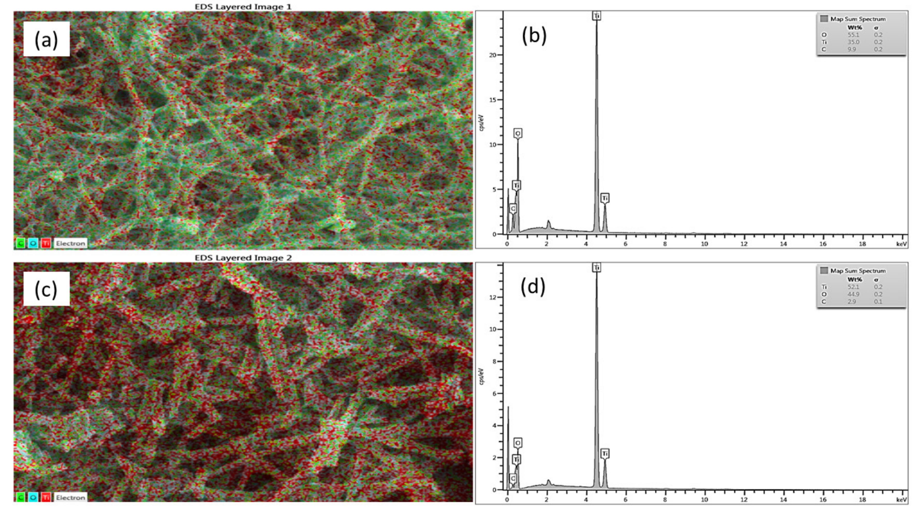
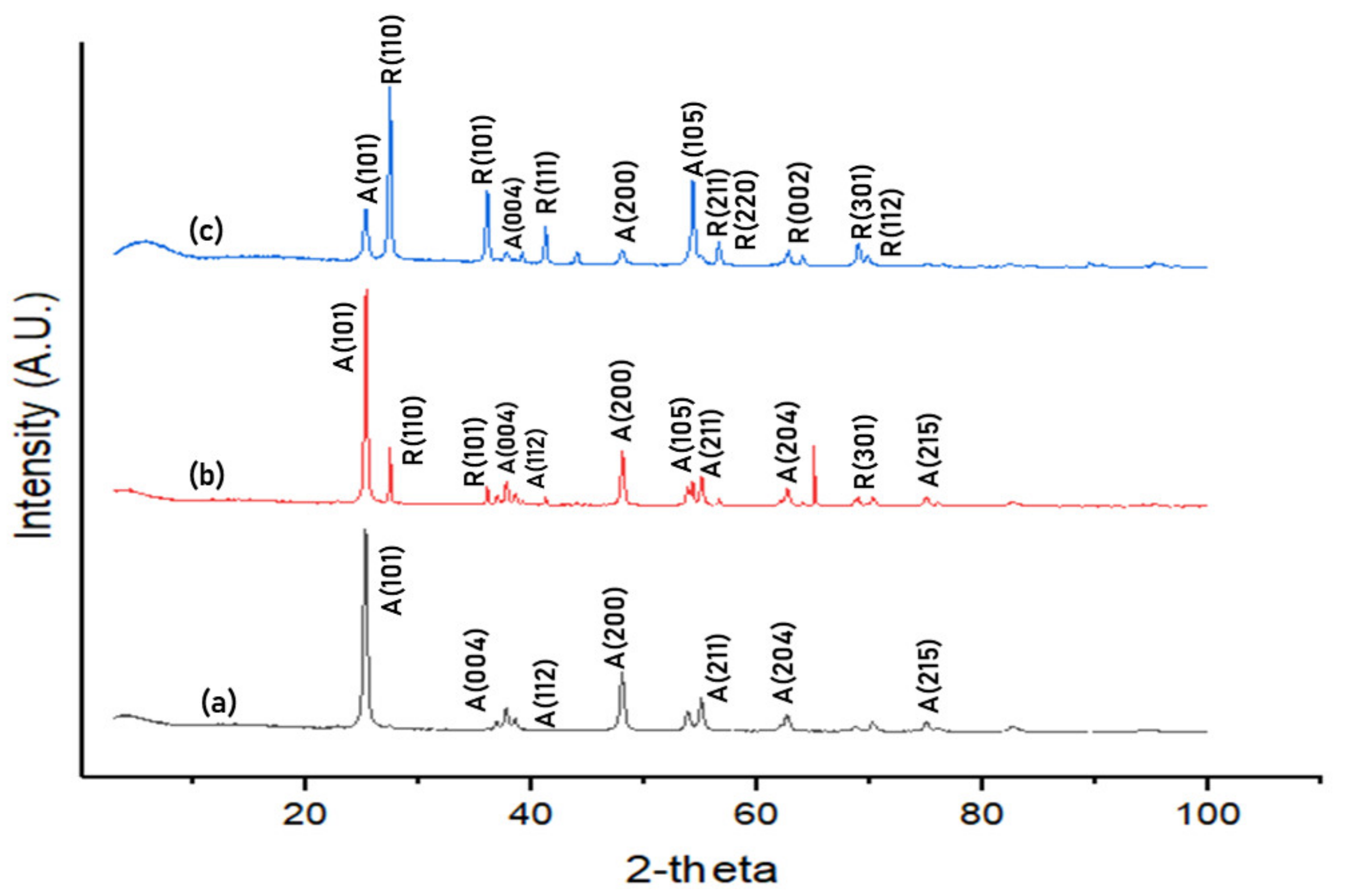
3.1. Characterisation
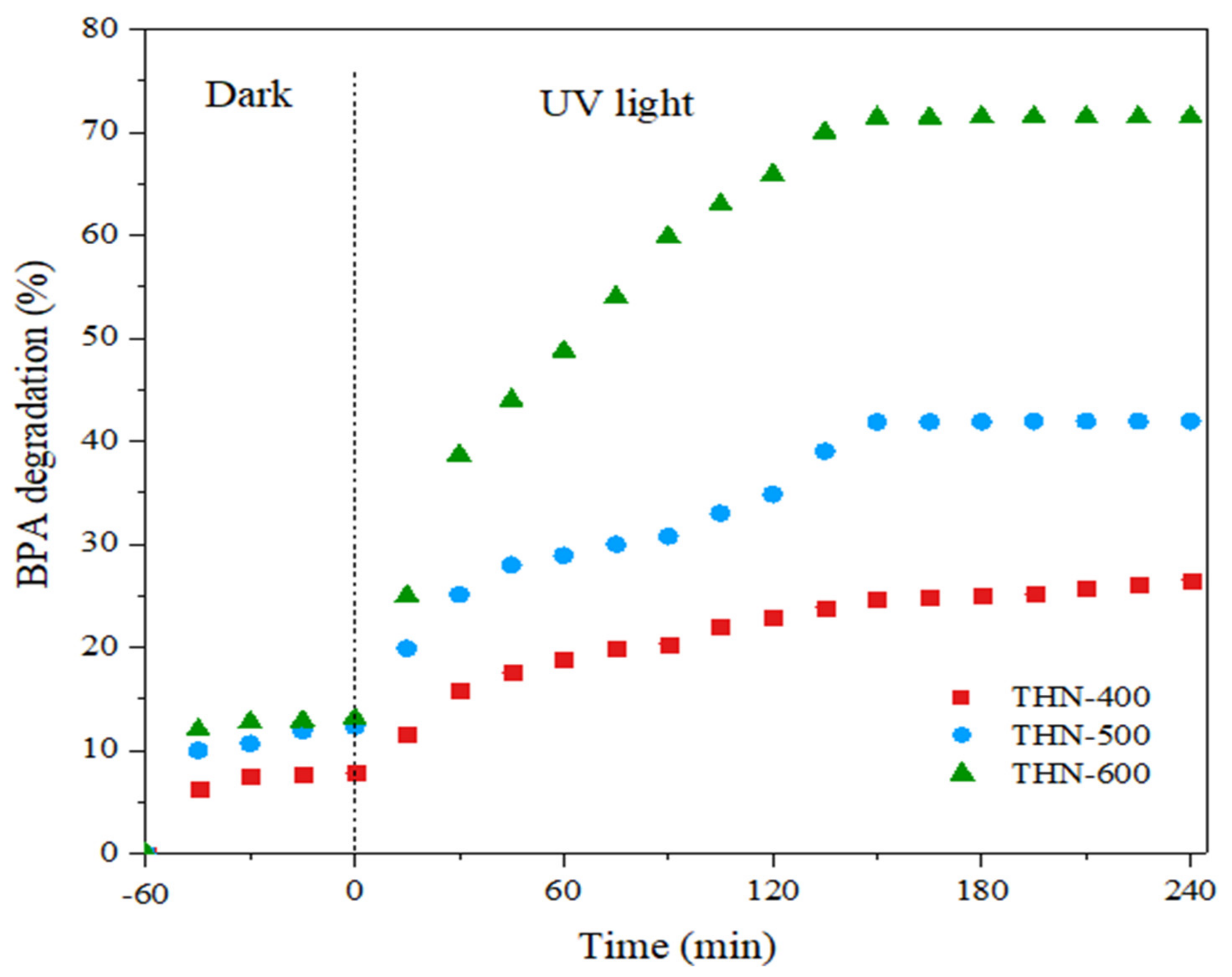
3.2. Photocatalytic Degradation Performance
3.3. Assembly and Recyclability of Photocatalysts
4. Conclusions
Author Contributions
Funding
Institutional Review Board Statement
Informed Consent Statement
Data Availability Statement
Acknowledgments
Conflicts of Interest
References
- Kwan, C.S.; Takada, H. Release of additives and monomers from plastic wastes. In Hazardous Chemicals Associated with Plastics in the Marine Environment; Springer: Berlin, Germany, 2016; pp. 51–70. [Google Scholar]
- Schug, T.T.; Birnbaum, L.S. Human Health Effects of Bisphenol A. In Toxicants in Food Packaging and Household Plastics: Molecular and Integrative Toxicology; Snedeker, S., Ed.; Springer: London, UK, 2014; pp. 1–29. [Google Scholar] [CrossRef]
- Campinas, M.; Viegas, R.M.C.; Coelho, R.; Lucas, H.; Rosa, M.J. Adsorption/Coagulation/Ceramic Microfiltration for Treating Challenging Waters for Drinking Water Production. Membranes 2021, 11, 91. [Google Scholar] [CrossRef]
- N’Diaye, J.; Poorahong, S.; Hmam, O.; Jiménez, G.C.; Izquierdo, R.; Siaj, M. Reduced Graphene Oxide-Based Foam as an Endocrine Disruptor Adsorbent in Aqueous Solutions. Membranes 2020, 10, 340. [Google Scholar] [CrossRef]
- Kumar, L.; Singh, S.; Horechyy, A.; Fery, A.; Nandan, B. Block Copolymer Template-Directed Catalytic Systems: Recent Progress and Perspectives. Membranes 2021, 11, 318. [Google Scholar] [CrossRef] [PubMed]
- Pan, J.; Dong, Z.; Wang, B.; Jiang, Z.; Zhao, C.; Wang, J.; Song, C.; Zheng, Y.; Li, C. The enhancement of photocatalytic hydrogen production via Ti3+ self-doping black TiO2/g-C3N4 hollow core-shell nano-heterojunction. Appl. Catal. B 2019, 242, 92–99. [Google Scholar] [CrossRef]
- Shakeel, M.; Li, B.; Arif, M.; Yasin, G.; Rehman, W.; Khan, A.U.; Khan, S.; Khan, A.; Ali, J. Controlled Synthesis of highly proficient and durable hollow hierarchical heterostructured (Ag-AgBr/HHST): A UV and Visible light active photocatalyst in deg-radation of organic pollutants. Appl. Catal. B 2018, 227, 433–445. [Google Scholar] [CrossRef]
- Zhao, Y.; Pan, K.; Wei, S.; Zhang, B. Template-free hydrothermal synthesis of 3D hollow aggregate spherical structure WO3 nano-plates and photocatalytic properties. Mater. Res. Bull. 2018, 101, 280–286. [Google Scholar] [CrossRef]
- Yang, Z.; Lu, J.; Ye, W.; Yu, C.; Chang, Y. Preparation of Pt/TiO2 hollow nanofibers with highly visible light photocatalytic activity. Appl. Surf. Sci. 2017, 392, 472–480. [Google Scholar] [CrossRef]
- Liu, H.; Han, C.; Shao, C.; Yang, S.; Li, X.; Li, B.; Li, X.; Ma, J.; Liu, Y. ZnO/ZnFe2O4 Janus Hollow Nanofibers with Magnetic Separability for Photocatalytic Degradation of Water-Soluble Organic Dyes. ACS Appl. Nano Mater. 2019, 2, 4879–4890. [Google Scholar] [CrossRef]
- Kumar, L.; Singh, S.; Horechyy, A.; Formanek, P.; Hübner, R.; Albrecht, V.; Weißpflog, J.; Schwarz, S.; Puneet, P.; Nandan, B. Hollow Au@TiO2 porous electrospun nanofibers for catalytic applications. RSC Adv. 2020, 10, 6592–6602. [Google Scholar] [CrossRef] [Green Version]
- Baranowska-Wójcik, E.; Szwajgier, D.; Oleszczuk, P.; Winiarska-Mieczan, A. Effects of Titanium Dioxide Nanoparticles Exposure on Human Health—A Review. Biol. Trace Elem. Res. 2020, 193, 118–129. [Google Scholar] [CrossRef] [Green Version]
- Argurio, P.; Fontananova, E.; Molinari, R.; Drioli, E. Photocatalytic Membranes in Photocatalytic Membrane Reactors. Processes 2018, 6, 162. [Google Scholar] [CrossRef] [Green Version]
- Nasrollahi, N.; Ghalamchi, L.; Vatanpour, V.; Khataee, A. Photocatalytic-membrane technology: A critical review for mem-brane fouling mitigation. J. Ind. Eng. Chem. 2021, 93, 101–116. [Google Scholar] [CrossRef]
- Ramezanalizadeh, H.; Manteghi, F. Immobilization of mixed cobalt/nickel metal-organic framework on a magnetic BiFeO3: A highly efficient separable photocatalyst for degradation of water pollutions. J. Photochem. Photobiol. A Chem. 2017, 346, 89–104. [Google Scholar] [CrossRef]
- Espíndola, J.C.; Cristóvão, R.O.; Mendes, A.; Boaventura, R.A.R.; Vilar, V.J.P. Photocatalytic membrane reactor per-formance towards oxytetracycline removal from synthetic and real matrices: Suspended vs. immobilized TiO2-P25. Chem. Eng. J. 2019, 378, 122114. [Google Scholar] [CrossRef]
- Li, A.; Han, K.; Zhou, Y.; Ye, H.; Liu, G.; Kung, H.H. Incorporating multivalent metal cations into graphene oxide: Towards highly-aqueous-stable free-standing membrane via vacuum filtration with polymeric filters. Mater. Today Commun. 2017, 11, 139–146. [Google Scholar] [CrossRef]
- Yuan, G.; Xiang, J.; Jin, H.; Jin, Y.; Wu, L.; Zhang, Y.; Mentbayeva, A.; Bakenov, Z. Flexible free-standing Na4Mn9O18/reduced graphene oxide composite film as a cathode for sodium rechargeable hybrid aqueous battery. Electrochim. Acta 2018, 259, 647–654. [Google Scholar] [CrossRef]
- Zhao, S.; Li, M.; Wu, X.; Yu, S.; Zhang, W.; Luo, J.; Wang, J.; Geng, Y.; Gou, Q.; Sun, K. Graphene-based free-standing bendable films: Designs, fabrications, and applications. Mater. Today Adv. 2020, 6, 100060. [Google Scholar] [CrossRef]
- Wang, X.; Chen, L.; Li, F.; Zhang, S.; Chen, X.; Yin, J. Synthesis of hollow NiO nanostructures and their application for su-percapacitor electrode. Ionics 2019, 25, 697–705. [Google Scholar] [CrossRef]
- Sheikhattar, M.; Attar, H.; Sharafi, S.; Carty, W.M. Influence of surface crystallinity on the surface roughness of different ceramic glazes. Mater. Charact. 2016, 118, 570–574. [Google Scholar] [CrossRef]
- Uddin, M.J.; Cesano, F.; Chowdhury, A.R.; Trad, T.; Cravanzola, S.; Martra, G.; Mino, L.; Zecchina, A.; Scarano, D. Surface Structure and Phase Composition of TiO2 P25 Particles After Thermal Treatments and HF Etching. Front. Mater. 2020, 7. [Google Scholar] [CrossRef]
- Dong, W.; Zhang, L.; Li, B.; Wang, L.; Wang, G.; Li, X.; Chen, B.; Li, C. Preparation of hollow multiple-Ag-nanoclustes-C-shell nanostructures and their catalytic properties. Appl. Catal. B Environ. 2016, 180, 13–19. [Google Scholar] [CrossRef]
- Liu, X.; Sayed, M.; Bie, C.; Cheng, B.; Hu, B.; Yu, J.; Zhang, L. Hollow CdS-based photocatalysts. J. Mater. 2020, 7, 419–439. [Google Scholar] [CrossRef]
- Prieto, G.; Tüysüz, H.; Duyckaerts, N.; Knossalla, J.; Wang, G.-H.; Schüth, F. Hollow Nano- and Microstructures as Catalysts. Chem. Rev. 2016, 116, 14056–14119. [Google Scholar] [CrossRef] [PubMed]
- Wang, L.; Cui, H.; Wang, L.; Han, X.; Wang, X. Floating microparticles of ZnIn2S4@ hollow glass microsphere for enhanced photocatalytic activity. Int. J. Hydrogen Energy 2021, 46, 9678–9689. [Google Scholar] [CrossRef]
- Laskar, I.I.; Hashisho, Z. Insights into modeling adsorption equilibria of single and multicomponent systems of organic and water vapors. Sep. Purif. Technol. 2020, 241, 116681. [Google Scholar] [CrossRef]
- Vequizo, J.J.; Matsunaga, H.; Ishiku, T.; Kamimura, S.; Ohno, T.; Yamakata, A. Trapping-Induced Enhancement of Photocatalytic Activity on Brookite TiO2 Powders: Comparison with Anatase and Rutile TiO2 Powders. ACS Catal. 2017, 7, 2644–2651. [Google Scholar] [CrossRef]
- Ma, Y.; Ni, M.; Li, S. Optimization of Malachite Green Removal from Water by TiO2 Nanoparticles under UV Irradiation. Nanomaterials 2018, 8, 428. [Google Scholar] [CrossRef] [Green Version]
- Iglesias, O.; Rivero, M.J.; Urtiaga, A.M.; Ortiz, I. Membrane-based photocatalytic systems for process intensification. Chem. Eng. J. 2016, 305, 136–148. [Google Scholar] [CrossRef]
- Nawaz, R.; Kait, C.F.; Chia, H.Y.; Isa, M.H.; Huei, L.W.; Sahrin, N.T.; Khan, N. Countering major challenges confronting photocatalytic technology for the remediation of treated palm oil mill effluent: A review. Environ. Technol. Innov. 2021, 23, 101764. [Google Scholar] [CrossRef]
- Li, J.; Li, X.; Wu, G.; Guo, J.; Yin, X.; Mu, M. Construction of 2D Co-TCPP MOF decorated on B-TiO2−X nanosheets: Oxygen vacancy and 2D–2D heterojunctions for enhancing visible light-driven photocatalytic degradation of bisphenol A. J. Environ. Chem. Eng. 2021, 9, 106723. [Google Scholar] [CrossRef]
- Ye, C.; Hu, K.; Niu, Z.; Chenlu, Y.; Zhang, L.; Yan, K. Controllable synthesis of rhombohedral α-Fe2O3 efficient for photocatalytic degradation of bisphenol A. J. Water Process Eng. 2018, 27, 205–210. [Google Scholar] [CrossRef]
- Yan, X.; Yi, C.; Wang, Y.; Cao, W.; Mao, D.; Ou, Q.; Shen, P.; Wang, H. Multi-catalysis of nano-zinc oxide for bisphenol A degradation in a dielectric barrier discharge plasma system: Effect and mechanism. Sep. Purif. Technol. 2019, 231, 115897. [Google Scholar] [CrossRef]
- Ahamad, T.; Naushad, M.; Alzaharani, Y.; Alshehri, S.M. Photocatalytic degradation of bisphenol-A with g-C3N4/MoS2-PANI nanocomposite: Kinetics, main active species, intermediates and pathways. J. Mol. Liq. 2020, 311, 113339. [Google Scholar] [CrossRef]
- Sharma, J.; Mishra, I.; Kumar, V. Mechanistic study of photo-oxidation of Bisphenol-A (BPA) with hydrogen peroxide (H2O2) and sodium persulfate (SPS). J. Environ. Manag. 2016, 166, 12–22. [Google Scholar] [CrossRef]
- Zhao, C.; Wang, J.; Chen, X.; Wang, Z.; Ji, H.; Chen, L.; Liu, W.; Wang, C.-C. Bifunctional Bi12O17Cl2/MIL-100(Fe) composites toward photocatalytic Cr(VI) sequestration and activation of persulfate for bisphenol A degradation. Sci. Total Environ. 2021, 752, 141901. [Google Scholar] [CrossRef]


| Photocatalyst | Specific Surface Area (m2/kg) | Specific Pore Volume (m3/kg) |
|---|---|---|
| THN-400 | 13.322 × 10³ | 6.354 × 10⁻⁵ |
| THN-500 | 43.499 × 10³ | 2.349 × 10⁻⁴ |
| THN-600 | 81.277 × 10³ | 3.272 × 10⁻⁴ |
| Compound | Molecular Structure | Retention Time, TR (min) |
|---|---|---|
| Bisphenol A | 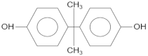 | 16.4 |
| 4-isopropanolphenol | 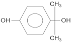 | 13.5 |
| Phenol | 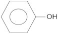 | 12.8 |
| Hydroquinone | 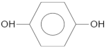 | 5.2 |
Publisher’s Note: MDPI stays neutral with regard to jurisdictional claims in published maps and institutional affiliations. |
© 2022 by the authors. Licensee MDPI, Basel, Switzerland. This article is an open access article distributed under the terms and conditions of the Creative Commons Attribution (CC BY) license (https://creativecommons.org/licenses/by/4.0/).
Share and Cite
Jafri, N.N.M.; Jaafar, J.; Aziz, F.; Salleh, W.N.W.; Yusof, N.; Othman, M.H.D.; Rahman, M.A.; Ismail, A.F.; Rahman, R.A.; Khongnakorn, W. Development of Free-Standing Titanium Dioxide Hollow Nanofibers Photocatalyst with Enhanced Recyclability. Membranes 2022, 12, 342. https://doi.org/10.3390/membranes12030342
Jafri NNM, Jaafar J, Aziz F, Salleh WNW, Yusof N, Othman MHD, Rahman MA, Ismail AF, Rahman RA, Khongnakorn W. Development of Free-Standing Titanium Dioxide Hollow Nanofibers Photocatalyst with Enhanced Recyclability. Membranes. 2022; 12(3):342. https://doi.org/10.3390/membranes12030342
Chicago/Turabian StyleJafri, Nurul Natasha Mohammad, Juhana Jaafar, Farhana Aziz, Wan Norharyati Wan Salleh, Norhaniza Yusof, Mohd Hafiz Dzarfan Othman, Mukhlis A. Rahman, Ahmad Fauzi Ismail, Roshanida A. Rahman, and Watsa Khongnakorn. 2022. "Development of Free-Standing Titanium Dioxide Hollow Nanofibers Photocatalyst with Enhanced Recyclability" Membranes 12, no. 3: 342. https://doi.org/10.3390/membranes12030342