Abstract
This systematic review was aimed at gathering the clinical and technical applications of CAD/CAM technology for craniofacial implant placement and processing of auricular prostheses based on clinical cases. According to the Preferred Reporting Items for Systematic Reviews and Meta-Analysis (PRISMA) guidelines, an electronic data search was performed. Human clinical studies utilizing digital planning, designing, and printing systems for craniofacial implant placement and processing of auricular prostheses for prosthetic rehabilitation of auricular defects were included. Following a data search, a total of 36 clinical human studies were included, which were digitally planned and executed through various virtual software to rehabilitate auricular defects. Preoperative data were collected mainly through computed tomography scans (CT scans) (55 cases); meanwhile, the most common laser scanners were the 3dMDface System (3dMD LLC, Atlanta, Georgia, USA) (6 cases) and the 3 Shape scanner (3 Shape, Copenhagen, Denmark) (6 cases). The most common digital design software are Mimics Software (Mimics Innovation Suite, Materialize, Leuven, Belgium) (18 cases), Freeform software (Freeform, NC, USA) (13 cases), and 3 Shape software (3 Shape, Copenhagen, Denmark) (12 cases). Surgical templates were designed and utilized in 35 cases to place 88 craniofacial implants in auricular defect areas. The most common craniofacial implants were Vistafix craniofacial implants (Entific Medical Systems, Goteborg, Sweden) in 22 cases. A surgical navigation system was used to place 20 craniofacial implants in the mastoid bone. Digital applications of CAD/CAM technology include, but are not limited to, study models, mirrored replicas of intact ears, molds, retentive attachments, customized implants, substructures, and silicone prostheses. The included studies demonstrated a predictable clinical outcome, reduced the patient’s visits, and completed the prosthetic rehabilitation in reasonable time and at reasonable cost. However, equipment costs and trained technical staff were highlighted as possible limitations to the use of CAD/CAM systems.
1. Introduction
Morphological deformity of the external ear, referred to as an auricular defect, can arise from surgical intervention following tumor resection, trauma, or congenital malformation [1,2,3,4]. There are two approaches to manage these defects: surgical reconstruction of the external ear or fabrication of auricular prostheses. Auricular prostheses are artificial, removable devices that replicate the morphology of the external ear and are customized to address the cosmetic and psychological challenges posed by auricular defects [3,4]. In principle, the surgical reconstruction of the ear is performed through the use of rib cartilage, which is carved intra-operatively to provide the auricular matrix, or by using a synthetic material framework [5]. Surgical reconstruction comprises multiple surgical revisions to obtain an acceptable outcome [6]. However, reconstruction of the ear through surgical procedures is generally difficult and often fails to provide a satisfactory outcome [3].
A failed autogenous reconstruction is one of the major indications for prosthetic rehabilitation, as fibrosis from previous surgeries makes it difficult to reconstruct the external ear surgically [7]. Prosthetic rehabilitation for auricular defects has been carried out for decades for cosmetic reasons; however, the development of the craniofacial implant (CI) was the milestone that provided optimum retention, support, and stability to the auricular prosthesis [8,9]. The bone thickness in the mastoid region varies between 2.5 mm and 5.5 mm; therefore, the length of craniofacial implants is usually selected between 3 mm and 5 mm to retain the auricular prostheses [10,11]. Upon osseointegration, CI can be used in combination with various types of retentive attachments (clip bar attachment, magnet attachment, locator attachment, or combination of these types of attachments, i.e., bar with locator attachments or bar with ERA attachment) to retain the auricular prostheses [11,12,13].
Successful auricular defect rehabilitation depends on comprehensive preoperative planning. The presence of mastoid air cells and the proximity of facial nerves and cranial structures make it challenging for maxillofacial surgeons [14]. The use of non-contact and non-invasive medical imaging (CT scan, CBCT, and MRI) has provided the solution to plan preoperatively and thereby prevent damage to the adjacent anatomical structures [14,15]. These imaging techniques provide detailed hard and soft tissue details to plan the precise location of implants in relation to the prosthesis [14,15]. Furthermore, laser scanners can record the surface details; however, the sharp groves and skin folds could be missing in these scan images [16]. CT scans can provide a complete image, but at the expense of X-ray radiation. Similarly, MRI can also provide complete images for 3D models; however, the resolution is low as compared to CT scan images.
Digital planning software have further accelerated the planning and designing stages of rehabilitation procedures in the last couple of decades [17,18]. This digital workflow requires the hard and soft tissue details of the affected and non-affected areas, which can be acquired through CT scans, MRIs, and laser scans [15]. The scanned images from radiographic techniques are in DICOM format, which is converted into STL format for modeling software [19]. Digital designing software uses these data to mirror the structures from the normal side to the defect side to construct the retentive attachments, molds, models, and surgical templates for implant placement [20,21]. Following the computer-aided design (CAD) step, physical models, molds, surgical templates, and even prostheses can be printed through the computer-aided manufacturing (CAM) process by using various materials, i.e., resins, acrylics, thermoplastic waxes, plastics, and metals [17,20,21].
Additionally, surgical navigation systems have added a dynamic approach to the digital workflow for rehabilitation procedures by enabling the surgeons to precisely control the position of instruments during the surgical procedures through multi-planner medical imaging views [10,22]. Once the navigation pointer touches the tissues on the surgical site, the virtual pointer recognizes the exact location on radiographic images, providing the surgeon with the ability to navigate through the anatomical structures while keeping the tract on the virtual anatomical map [22].
The cosmetic limitations of surgical auricular reconstruction paved the way for prosthetic rehabilitation by means of auricular prostheses [3,6]. In recent years, advances in digital technology, specifically Computer-Aided Design and Computer-Aided Manufacturing (CAD/CAM), have emerged as promising tools for enhancing preoperative planning, design, and fabrication of auricular prostheses. The application of digital technology for the fabrication of facial prostheses has reduced the patient’s visits, the clinical and laboratory time spent on each visit, and the steps of the fabrication of prostheses with a predictable outcome [23]. Patients can visualize the proposed plan before undergoing the surgical or prosthetic phases. Overall, CAD/CAM systems have been used for the preoperative planning, fabrication of surgical templates, models, molds, substructures, customized implants, and surgical navigation for prosthetic rehabilitation of auricular defects. This systematic review aims to comprehensively examine the clinical and technical applications of CAD/CAM technology in the preoperative planning, designing, and manufacturing processes of auricular prostheses for individuals with auricular defects. To our knowledge, while various studies have discussed the individual components of CAD/CAM technology and auricular prostheses, a comprehensive analysis of their integrated application in clinical practice remains scarce. By synthesizing available clinical data, this review seeks to offer insights into the effective utilization of CAD/CAM technology for enhancing prosthetic rehabilitation outcomes.
2. Materials and Methods
A systematic review was performed based on the protocol of Preferred Reporting Items for Systematic Reviews and Meta-Analyses (PRISMA) [24] to determine the PICO (patients (P), investigations (I), comparison (C), and outcomes (O)) question.
Patients: Patient having an auricular defect
Interventions: Applications of CAD/CAM-based systems for planning, designing, and manufacturing of auricular prostheses and craniofacial implant placement.
Comparison: Not applicable.
Outcome: Fabrication of auricular prostheses.
Therefore, the established question was adapted to the PIO question: “In patients with auricular defects (P), what are the technical and clinical applications of CAD/CAM technology for craniofacial implant placement (I) and the manufacturing of auricular prostheses (O)?”. This was performed while also considering that comparison (C) was not applicable in this systematic review.
2.1. Search Strategy
The electronic search was executed by using the following combinations of terms: (Prostheses AND Planning AND Guide).
Prosthesis: (auricular prostheses OR ear prostheses OR silicone auricular prosthesis) AND Planning: (software planning OR scanning OR CAD/CAM OR digital OR navigation OR 3D) AND Guide: (implants OR extraoral implants OR craniofacial implants OR surgical template OR surgical guide OR printed guide OR guided surgery OR navigation system).
2.2. Eligibility Criteria
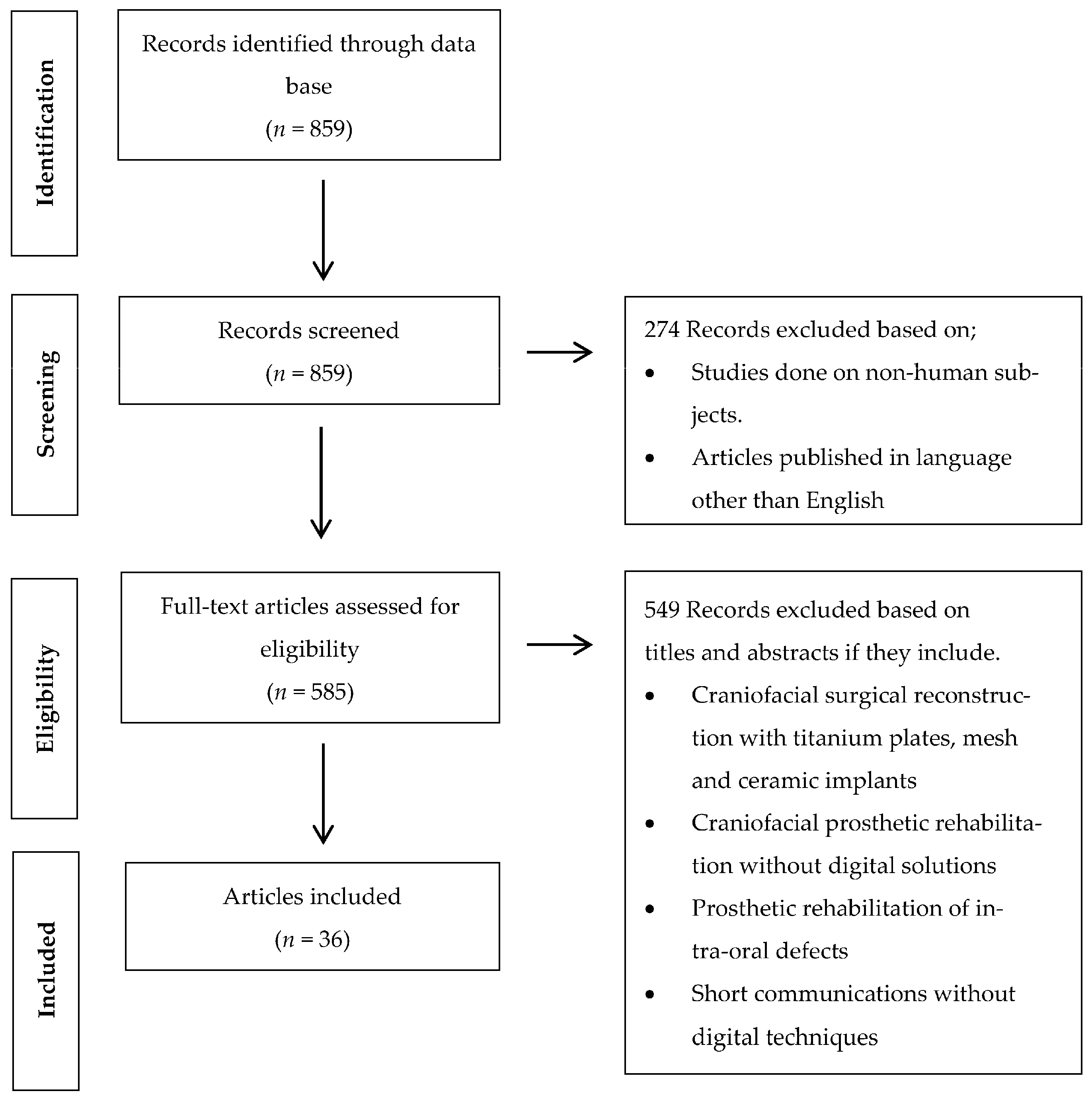
Clinical human studies published in the English language between January 2000 and May 2023 were reviewed. The inclusion criteria were comprised of randomized control trials, case control studies, case reports, cohort studies, and case series utilizing digital software and CAD/CAM technology for orbital implant placement and manufacturing of auricular prostheses. The exclusion criteria included systematic reviews, animal studies, case reports, in vitro studies, and finite element analysis (FEA) studies executed without the use of digital software and CAD/CAM systems (Figure 1).

Figure 1.
Flow chart of the study’s selection process and screening methodology.
2.3. Source of Information
An electronic search was conducted for published articles between January 2000 and May 2023 in the National Library of Medicine (MEDLINE/PubMed) database.
Furthermore, a manual search of the published articles between January 2000 and May 2023 was also executed: The Journal of Prosthodontics, The Journal of Oral Rehabilitation, the International Journal of Prosthodontics, The Journal of Prosthetic Dentistry, The Journal of Oral Implantology, The Journal of Prosthodontic Research, The International Journal of Oral and Maxillofacial Implants, Clinical Oral Implants Research, International Journal of Oral and Maxillofacial Surgery, Journal of Stomatology, Journal of Oral and Maxillofacial Surgery, British Journal of Oral and Maxillofacial Surgery, Journal of Cranio-maxillo-facial surgery, Oral and Maxillofacial Surgery, Implant Dentistry, and Related Research.
2.4. Study Selection
The studies were reviewed by two independent reviewers (W.T. and P.M.M.) and selected on the basis of their titles and abstracts from the electronic search. Those studies that fulfilled the inclusion criteria or contained limited data in the abstract to reach the final decision were collected and reviewed. Disagreements among the authors were rectified after discussion.
2.5. Data Extraction
The useful data from the included studies were transferred to the standard designed form: authors, publication year, purpose of the digital planning, preoperative data, software used, printers utilized, materials for printing, number of implants placed, and implant systems in each case (Table 1). Authors were contacted for possible missing data.
2.6. Risk of Bias in Individual Studies
Two independent reviewers (W.T. and P.M.M.) evaluated the quality of the included studies. In case of a conflict of agreement regarding any publication, a third reviewer (A.R.P.) was contacted. For evaluation, the critical tools of the Joanna Briggs Institute [25] (JBI) for case series and case reports were utilized based on the type of included articles. The bias was evaluated on the basis of the list of 10 questions for case series and 8 questions for case reports, respectively. The questions listed in Table 2a–c and Table 3a,b concern the risk of bias. Eventually, an assessment was performed through an overall appraisal to determine if the risk of bias was low (inclusion of the study), high (exclusion of the study), or uncertain (more information was needed). We refer to it as a low risk of bias if the answer “yes” was ≥50%, an uncertain risk of bias if the answer “unclear” was ≥50%, and a high risk of bias if the answer “no” was ≥50%.

Table 1.
Digital planning for the prosthetic rehabilitation of auricular defects.
Table 1.
Digital planning for the prosthetic rehabilitation of auricular defects.
| Publications | No. of Cases | Purpose of Software Planning | Pre-Op Data for Digital Planning | Software | Printer/Miller | Printing Materials | Navigation System (Yes/No) | Location & No. of Implants | Implants System |
|---|---|---|---|---|---|---|---|---|---|
| Ciocca L., Scotti R. 2004 [26] | 1 | Fabrication of ear model | Minolta VIVID 900 3D laser scanner (Konica Minolta, Osaka, Japan) | Polygone editing tool (Minolta Co, Osaka, Japan), Rapidform CAD software (INUS Technology, Seoul, South Korea) | Z Printer 310 (Z Corp, Cambridge, MA, USA) | Powder and sealant from Z Corp. (Z Corp., Cambridge, MA, USA) | No | No | No |
| Sykes et al., 2004 [27] | 1 | Fabrication of ear model | Breuckmann OptoTOP scanner system (Breuckmann OptoTOP, Germany) | Polyworks software (InnovMetric Software), Freeform software (Freeform, NC, USA) | Thermojet printer | Wax material | No | No | No |
| Jiao et al., 2004 [28] | 1 | Fabrication of ear model | CT scan | Magics RP image ware (Materialise, Leuven, Belgium), Freeform software (Freeform, NC, USA) | Zippy-I RP machine (Kinergy Mechatronics, Singapore) | NM | No | No | No |
| Ciocca L et al., 2007 [29] | 1 | Fabrication of mold for auricular prosthesis and acrylic substructure | Minolta VIVID 900 3D laser scanner (Konica Minolta, Osaka, Japan) | Rapidform CAD software (INUS Technology, Seoul, South Korea), Software, Polygone editing tool (Minolta Co., Osaka, Japan) | Z Printer 310 (Z Corp, Cambridge, MA, USA) | Powder and sealant from Z Corp. (Z Corp., Cambridge, MA, USA) | No | No | No |
| Kurtulmus et al., 2009 [17] | 1 | Virtual implant planning | CT Scan | Implant 3D, Media Lab Software, 3D-Doctor software (Able Coorporation, Lexington, MA, USA) | NM | NM | No | No | No |
| Ciocca L et al., 2009 [30] | 1 | Surgical template for implant placement | CT, NextEngine Desktop 3D Scanner (NextEngine, Santa Monica, CA, USA) | Rapidform CAD software (INUS Technology, Seoul, South Korea) | Rapid prototyping machine (Z310Plus; Z Corp., Burlington, MA, USA) | NM | No | Right mastoid bone; 3 implants | NM |
| Turgut et al., 2009 [31] | 10 | Fabrication of ear model | CT scan | Modeling software (FreeForm Modeling Plus System, SensAble, Boston, MA) | Selective laser sintering (SLS) system (DTM Corp., Austin, TX, USA) | NM | No | No | No |
| Ciocca. L et al., 2010 [32] | 1 | Fabrication of mold for auricular prosthesis | NextEngine Desktop 3D Scanner (NextEngine, Santa Monica, CA, USA) | NextEngine Scan studio software (NextEngine, CA, USA) | 3D printer (Stratasys, Eden Prairie, MN, USA) | ABS P400 jet (Stratasys, Eden Prairie, MN, USA) | No | No | No |
| Verma et al., 2010 [22] | 2 | Virtual planning and intraoperative navigation for implant placement | CT scan | Navigation system, Stryker iNtellect Cranial (Stryker Navigation system, MI, USA) | NM | NM | Yes | Left and Right mastoid regions; 4 implants | Vistafix implants (Cochlear, Lone Tree, USA) |
| De Crescenzio F et al., 2011 [33] | 1 | Fabrication of mold for auricular prosthesis | NextEngine Desktop 3D Scanner (NextEngine, Santa Monica, CA, USA) | Rapidform CAD software (INUS Technology, Seoul, South Korea), Rhinoceros Software v. 4.0 (Robert McNeel & Associates, USA) | 3D printer (Stratasys, Eden Prairie, MN, USA) | ABS P400 jet (Stratasys, Eden Prairie, MN, USA) | No | Right mastoid bone; 2 implants | Straumann implants (Institut Straumann AG, Basel, Switzerland |
| Liacouras et al., 2011 [34] | 1 | Designing and creation of digital model and mold fabrication | CT scan, 3D photography/imaging (3dMD cranial System; 3dMD, Atlanta, GA, USA) | Mimics Software (Mimics Innovation Suite, Materialise, Leuven, Belgium), Freeform software (Freeform, NC, USA) (14 cases), Geomagics Studio software (3D Systems, Rock Hill, SC, USA) | ZPrinter 450, using zp130 Powder and zb59 Binder; (Z Corp., Cambridge, MA, USA) | NM | No | No | No |
| Kolodney et al., 2011 [35] | 1 | Surgical template for implant placement | CT scan | Mimics Software (Mimics Innovation Suite, Materialise, Leuven, Belgium), SurgiCase software (Materialise LLC, Ann Arbor, MI, USA) | NM | Somos DMX 100 Resin material (Somos DSM, Desotech Inc., Elgin, Illinois, USA) | No | Right mastoid bone; 3 implants | NM |
| Karatas MO et al., 2011 [36] | 2 | Fabrication of ear models | CT scans | Mimics Software (Mimics Innovation Suite, Materialise, Leuven, Belgium) | 3D ink-jet FDM printer (Z Corp, Cambridge, MA, USA), Perfactory Standard SXGA+ stereolithography printer (Envisiontec Inc., Germany) | Acrylic material | No | No | No |
| Bai et al., 2012 [37] | 1 | Surgical template for implant placement | CT scan | Geomagics Studio software (3D Systems, Rock Hill, SC, USA), Mimics Software (Mimics Innovation Suite, Materialise, Leuven, Belgium) | Rapid Prototyping machine AFS-360 printer (Long yuan Technology Ltd., Beijing, China) | Resin material (Details NM) | No | Left mastoid region, 3 implants | NM |
| Reitemeier et al., 2012 [38] | 1 | Surgical template for implant placement | CT scan | Software (VoXim v6.1; IVS Solutions AG, Chemnitz, Germany) | FDM Vantage S; (Stratasys, Eden Prairie, MN, USA) | Acrylic resin template | No | Right mastoid region, 2 implants | Straumann implants (Straumann GmbH, Freiburg, Germany) |
| Hatamleh and Watson. 2013 [39] | 1 | Fabrication of ear model | 3Shape R700 scanner (3 Shape, Copenhagen, Denmark) | 3 Shape software (3 Shape, Copenhagen, Denmark) | Z-Corp Printer (Z Corp, Cambridge, MA, USA) | NM | No | 2 craniofacial implants | Vistafix craniofacial implants (Cochlear, Surrey, UK) |
| Bai et al., 2014 [40] | 6 | Fabrication of mold for auricular prosthesis | CT scan, structured-light 3D scanner (3DSS-STD-II, Digital Manu, Shanghai, China) | Mimics Software (Mimics Innovation Suite, Materialise, Leuven, Belgium) | Rapid Prototyping machine AFS-360 printer (Long yuan Technology Ltd., Beijing, China) | Resin material | No | No | No |
| Tam CK et al., 2014 [8] | 6 | Fabrication of ear model | CT scan, 3dMDFace (3dMD, Atlanta, USA) | Mimics Software (Mimics Innovation Suite, Materialise, Leuven, Belgium), Surgical navigation system (BrainLAB, Feldkirchen, Germany) | Fused Deposition Modeling (FDM) | NM | Surgical navigation system (BrainLAB, Feldkirchen, Germany) | 12 implants were placed in mastoid bone | Dental implants (Friadent, Dentsply, Mannheim, Germany) |
| Watson and Hatamleh 2014 [41] | 3 | Fabrication of ear model | 3Shape R700 scanner (3 Shape, Copenhagen, Denmark) | Software Z-Build (Z Corp, Cambridge, MA, USA) | 3D printer (Z Corp., Cambridge, MA, USA). | Gypsum (150 Powder) (Z Corp, Cambridge, MA, USA) | No | No | No |
| Wang et al., 2015 [42] | 1 | Fabrication of model for implant placement planning | EBCT scan | Geomagics Studio software (3D Systems, Rock Hill, SC, USA) | SLS machine (AFS-360; (Long yuan Technology Ltd., Beijing, China) | Resin material | No | 3 implants in right mastoid bone | Implants (MDIC; FMMU, China) |
| Nuseir et al., 2015 [43] | 1 | Surgical template for implant placement | CT scan | Mimics Software (Mimics Innovation Suite, Materialise, Leuven, Belgium) | 3D printer (Z Corp, Cambridge, MA, USA) | NM | No | Left mastoid region, 2 implants | Vistafix craniofacial implants (Cochlear, Surrey, UK |
| Choi et al., 2016 [44] | 2 | Planning for craniofacial implant placement | CT scan | BrainLAB software (BrainLAB AG, Munich, Germany) | No | No | Image guidance systems (IGS) (Brainlab AG, Munich, Germany). | 4 implants in mastoid bone | Vistafix craniofacial implants (Cochlear, Surrey, UK) |
| Weissler et al., 2017 [45] | 1 | Virtual planning and intraoperative navigation for implant placement | CT scan, Laser scan | iPlan Cranial 3.0 BrainLAB software (BrainLAB AG, Munich, Germany) | NM | NM | Yes | Left & Right mastoid region; 4 implants | Vistafix craniofacial implants (Cochlear, Surrey, UK) |
| Yadav et al., 2017 [46] | 1 | Fabrication of mold for auricular prosthesis | CT scan | 3D modeling software | NM | NM | No | No | No |
| Nafij Bin Jamayet et al., 2018 [47] | 1 | Fabrication of ear model | NextEngine Desktop 3D Scanner (NextEngine, Santa Monica, CA, USA) | NextEngine Scan studio software (NextEngine, CA, USA), Rapidworks 64 version 4.1.0. (3D system, Inc., Rock Hill, USA) | Objet30 Scholar 3D Printer (Stratasys, Eden Prairie, MN, USA) | NM | No | No | No |
| Unkovskiy et al., 2018 [48] | 1 | Fabrication of mold for auricular prosthesis | Artec Color 3D scanner (Artec 3D, Luxembourg) | Artec Studio Software (Artec 3D, Luxembourg), Z brush software (Pixologic, Inc., Los Angeles, CA, USA) | ProJet 3510 CPXPlus (3D Systems, Rock Hill, SC, USA), SPro 60 HD (3D Systems, Rock Hill, SC, USA) | VisiJet M3 Hi-Cast printer (3D Systems, Rock Hill, SC, USA) | No | No | No |
| Sanghavi, et al., 2018 [49] | 1 | Fabrication of ear model | CT scan | Freeform software (Freeform, NC, USA) | 3D printing technology (Stereolithography) | Acrylic photopolymeric material | No | No | No |
| Ferreira R, Vives P. 2019 [50] | 2 | Fabrication of custom titanium plate for locator attachments | CT scan | Materialise 3-matic software 9.0 (Materalise, Leuven, Belgium) | Selective laser melting | Titanium grade 2 | No | No | No |
| Vijverberg MA et al., 2019 [51] | 11 | Surgical template for implant placement | CT scan | 3 Shape software (3 Shape, Copenhagen, Denmark) | NM | Polyamide material (Oceanz BV, Ede, The Netherlands) | No | 31 VXI300 implants in mastoid bone | Vistafix implants (Cochlear Bone Anchored Solutions AB, Mölnlycke, Sweden) |
| Cevik and Kocacikli. 2020 [52] | 1 | Fabrication of mold for auricular prosthesis | Artec Color 3D scanner (Artec 3D, Luxembourg) | Artec studio 16 software (Artec 3D, Luxembourg) | FDM technology printer; MakerBot Replicator 2 (MakerBot Industries, Brooklyn, NY, USA) | Polylactic acid material (PLA) | No | No | No |
| McHutchion and Aalto. 2021 [53] | 5 | Fabrication of scan bodies and molds for auricular prosthesis | 3dMD flex System (3dMD LLC, Atlanta, Georgia, USA), 3Shape R700 scanner (3 Shape, Copenhagen, Denmark) | Geomagics Studio software (3D Systems, Rock Hill, SC, USA) | Stereolithography 3D printer Form2 (Formlabs Inc., Somerville, Massachusetts, USA) | Clear resin, white resin (Formlabs Inc., Somerville, Massachusetts, USA) | No | No | No |
| Domingue D. et al., 2021 [54] | 1 | Surgical template for implant placement | CBCT scan | Meshmixer (Autodesk Inc., USA), Blue Sky Plan software (Blue Sky Bio, LLC, USA) | CEL Robox 3D printer (CEL, Bristol, UK) | nGen colorFabb polymer material (Eastman Chemical Company, Belfeld, Netherlands) | No | 4 implants in right mastoid bone | Vistafix craniofacial implants (Cochlear, Surrey, UK) |
| Unkovskiy et al., 2021 [55] | 1 | Fabrication of ear model and substructure and printing of silicone auricular prosthesis | Pritiface 3D photogrammetry system (pritiface; pritidenta GmbH, Germany), 3Shape R700 scanner (3 Shape, Copenhagen, Denmark) | Exocad software (Exocad, GmbH, Darmstadt, Germany), Z brush software (Pixologic, Inc., USA) | Stereolithography (SLA) (Form 2; Formlabs) (Formlabs Inc., Somerville, Massachusetts, USA) | Resin material (Flexible; Formlabs) (Formlabs Inc., Somerville, Massachusetts, USA), ACEO silicone material (Drop-on-Demand ACEO; Wacker Chemie AG, Munich, Germany) | No | No | No |
| Dashti et al., 2022 [56] | 1 | Fabrication of working cast and bar | Artec Color 3D scanner (Artec 3D, Luxembourg), 3Shape R700 scanner (3 Shape, Copenhagen, Denmark) | Z brush software (Pixologic, Inc., USA), Exocad software (Exocad, GmbH, Darmstadt, Germany) | Stereolithography printer | PowerDent resin material (ProTech Transfer Co., Ltd., Bangkok, Thailand) | No | No | No |
| Hatamleh MM et al., 2022 [57] | 3 | Surgical template for implant placement | CT scan | CMF Pro Plan; Materialise | Form 2; Formlabs GmbH | NM | No | Patient 1: Right mastoid bone. 2 implants of 4 mm Patient 2: 2 implants on each side | Branemark; Cochlear Europe Ltd. |
| Heydenrych A et al., 2023 [58] | 1 | Surgical template for implant placement | CT scan | Materialise 3-matic software 9.0 (Materalise, Leuven, Belgium) | Selective laser sintering printer | Nylon PA 2200 | No | Right mastoid bone. 3 implants | No |
Abbreviations: CT: computed tomography; CBCT: cone-beam computed tomography; EBCT: electron beam computed tomography; Pre-op: preoperative; and NM: not mentioned.
Table 2.
(a) Risk of bias for the case reports. (b) Risk of bias for the case reports. (c) Risk of bias for the case reports.
Table 2.
(a) Risk of bias for the case reports. (b) Risk of bias for the case reports. (c) Risk of bias for the case reports.
| (a) | |||||||||
| Assessment | Author and Year | ||||||||
| Ciocca L, Scotti R. 2004 [26] | Sykes et al., 2004 [27] | Jiao et al., 2004 [28] | Ciocca L et al., 2007 [29] | Kurtulmus et al., 2009 [17] | Ciocca L et al., 2009 [30] | Ciocca. L et al., 2010 [32] | De Crescenzio F et al., 2011 [33] | ||
| Were patient’s demographic characteristics clearly described? | No | No | Yes | No | Yes | No | Yes | No | |
| Was the patient’s history clearly described and presented as a timeline? | No | No | Yes | No | Yes | No | Yes | No | |
| Was the current clinical condition of the patient on presentation clearly described? | No | Yes | Yes | No | Yes | Yes | Yes | Yes | |
| Were diagnostic tests or assessment methods and the results clearly described? | Unclear | Unclear | Unclear | Unclear | Unclear | Unclear | Unclear | Unclear | |
| Was the intervention(s) or treatment procedure(s) clearly described? | Yes | Yes | Yes | Yes | Yes | Yes | Yes | Yes | |
| Was the post-intervention clinical condition clearly described? | Yes | Yes | Yes | Yes | Yes | Yes | Yes | Yes | |
| Were adverse events (harms) or unanticipated events identified and described? | Yes | No | No | Yes | No | No | No | No | |
| Does the case report provide takeaway lessons? | Yes | Yes | Yes | Yes | Yes | Yes | Yes | Yes | |
| Overall appraisal | Included | Included | Included | Included | Included | Included | Included | Included | |
| (b) | |||||||||
| Assessment | Author and Year | ||||||||
| Liacouras et al., 2011 [34] | Kolodney et al., 2011 [35] | Bai et al., 2012 [37] | Reitemeier et al., 2012 [38] | Hatamleh and Watson. 2013 [39] | Wang et al., 2015 [42] | Nuseir et al., 2015 [43] | Weissler et al., 2017 [45] | ||
| Were patient’s demographic characteristics clearly described? | Yes | Yes | No | Yes | Yes | Yes | Yes | Yes | |
| Was the patient’s history clearly described and presented as a timeline? | Yes | Yes | No | Yes | Yes | Yes | Yes | Yes | |
| Was the current clinical condition of the patient on presentation clearly described? | Yes | Yes | No | Yes | Yes | Yes | Yes | Yes | |
| Were diagnostic tests or assessment methods and the results clearly described? | Unclear | Unclear | Unclear | Unclear | Unclear | Unclear | Unclear | Unclear | |
| Was the intervention(s) or treatment procedure(s) clearly described? | Yes | Yes | Yes | Yes | Yes | Yes | Yes | Yes | |
| Was the post-intervention clinical condition clearly described? | Yes | Yes | Yes | Yes | Yes | Yes | Yes | Yes | |
| Were adverse events (harms) or unanticipated events identified and described? | No | No | Yes | No | No | No | No | No | |
| Does the case report provide takeaway lessons? | Yes | Yes | Yes | Yes | Yes | No | Yes | Yes | |
| Overall appraisal | Included | Included | Included | Included | Included | Included | Included | Included | |
| (c) | |||||||||
| Assessment | Author and Year | ||||||||
| Yadav et al., 2017 [46] | Nafij Bin Jamayet et al., 2018 [47] | Unkovskiy et al., 2018 [48] | Sanghavi, et al., 2018 [49] | Cevik and Kocacikli. 2020 [52] | Domingue D. et al., 2021 [54] | Unkovskiy et al., 2021 [55] | Dashti et al., 2022 [56] | Heydenrych A et al., 2023 [58] | |
| Were patient’s demographic characteristics clearly described? | Yes | No | Yes | Yes | Yes | Yes | No | No | No |
| Was the patient’s history clearly described and presented as a timeline? | Yes | No | Yes | Yes | Yes | Yes | No | No | No |
| Was the current clinical condition of the patient at presentation clearly described? | Yes | No | Yes | Yes | Yes | Yes | No | Yes | Yes |
| Were diagnostic tests or assessment methods and the results clearly described? | Unclear | Unclear | Unclear | Unclear | Unclear | Unclear | Unclear | Unclear | Yes |
| Was the intervention(s) or treatment procedure(s) clearly described? | Yes | Yes | Yes | Yes | Yes | Yes | Yes | Yes | Yes |
| Was the post-intervention clinical condition clearly described? | Yes | Yes | Yes | Yes | No | Yes | Yes | Yes | Yes |
| Were adverse events (harms) or unanticipated events identified and described? | No | Yes | No | No | No | No | Yes | Yes | No |
| Does the case report provide takeaway lessons? | Yes | Yes | Yes | Yes | Yes | Yes | Yes | Yes | Yes |
| Overall appraisal | Included | Included | Included | Included | Included | Included | Included | Included | Included |
Table 3.
(a) Risk of bias for the case series. (b) Risk of bias for the case series.
Table 3.
(a) Risk of bias for the case series. (b) Risk of bias for the case series.
| (a) | |||||||
| Assessment | Author and Year | ||||||
| Turgut et al., 2009 [31] | Verma et al., 2010 [22] | Karatas MO et al., 2011 [36] | Bai et al., 2014 [40] | Tam CK et al., 2014 [8] | Watson and Hatamleh 2014 [41] | Choi et al., 2016 [44] | |
| Were there clear criteria for inclusion in the case series? | Yes | Yes | Yes | Yes | Yes | Yes | Yes |
| Was the condition measured in a standard, reliable way for all participants included in the case series? | Yes | Yes | Yes | Yes | Yes | Yes | Yes |
| Were valid methods used for identification of the condition for all participants included in the case series? | Yes | Yes | Yes | Yes | Yes | Yes | Yes |
| Did the case series have consecutive inclusion of participants? | Unclear | Unclear | Unclear | Unclear | Unclear | Unclear | Unclear |
| Did the case series have complete inclusion of participants? | Yes | Yes | Yes | Yes | Yes | Yes | Yes |
| Was there clear reporting of the demographics of the participants in the study? | Yes | Yes | No | Yes | Yes | Yes | Yes |
| Was there clear reporting of clinical information of the participants? | No | Yes | Yes | Yes | Yes | No | Yes |
| Were the outcomes or follow-up results of cases clearly reported? | Yes | Yes | Yes | Yes | Yes | Yes | Yes |
| Was there clear reporting of the presenting site(s)/clinic(s) demographic information? | No | No | No | Yes | Yes | Yes | Yes |
| Overall appraisal | Included | Included | Included | Included | Included | Included | Included |
| (b) | |||||||
| Assessment | Author and Year | ||||||
| Ferreira R, Vives P. 2019 [50] | Vijverberg MA et al., 2019 [51] | McHutchion and Aalto. 2021 [53] | Hatamleh MM et al., 2022 [57] | ||||
| Were there clear criteria for inclusion in the case series? | Yes | Yes | Yes | Yes | |||
| Was the condition measured in a standard, reliable way for all participants included in the case series? | Yes | Yes | Yes | Yes | |||
| Were valid methods used for identification of the condition for all participants included in the case series? | Yes | Yes | Yes | Yes | |||
| Did the case series have consecutive inclusion of participants? | Unclear | Yes | Yes | Yes | |||
| Did the case series have complete inclusion of participants? | Yes | Yes | Yes | Yes | |||
| Was there clear reporting of the demographics of the participants in the study? | Yes | Yes | Yes | Yes | |||
| Was there clear reporting of clinical information of the participants? | Yes | No | Yes | Yes | |||
| Were the outcomes or follow up results of cases clearly reported? | Yes | Yes | Yes | Yes | |||
| Was there clear reporting of the presenting site(s)/clinic(s) demographic information? | No | Yes | Yes | Yes | |||
| Overall appraisal | Included | Included | Included | Included | |||
3. Results
3.1. Study Selection
The term was searched in the PubMed database. The literature search and the selection process have been summarized in Figure 1. Since most of the digital planning and designing developments have been noticed in the past two decades, the search strategy was decided to gather data within the time frame of January 2000 to May 2023, which yielded 806 studies. Two hundred and sixty-six (266) studies were excluded through the language (English) and human-based studies filters. Thereby, 540 studies were thoroughly screened based on their titles and abstracts in accordance with the inclusion and exclusion criteria, which led to the further exclusion of 504 studies on the basis of their study design and rehabilitation techniques (rehabilitation of auricular defects performed through surgical reconstruction and prosthetic rehabilitation performed through conventional procedures without digital planning and designing procedures). A total of 36 studies were included after reading full-text papers, which involved clinical cases digitally planned and processed for prosthetic rehabilitation of auricular defects. (Table 1) Due to the quality and data heterogeneity of the included studies, a meta-analysis could not be executed.
3.2. Study Characteristics
3.2.1. CAD/CAM Technology Applications for Prosthetic and Surgical Purposes
The included studies discussed the following applications of digital technology for prosthetic rehabilitation of auricular defects: surgical templates (27 cases), fabrication of ear models (30 cases), fabrication of molds for silicone packing (17 cases), customized scan bodies (1 case), and custom titanium plates for locator attachments fabricated with grade 2 titanium (1 case). A surgical navigation system was used to place craniofacial implants for prosthetic rehabilitation of auricular defects (2 cases).
3.2.2. Preoperative Record for Digital Planning
Digital planning requires preoperative data for surgical and prosthetic procedures. The following modalities were used to gain virtual data for preoperative planning: non-contact medical images (CT scans, CBCT, and EBCT), laser scans, 3D structured light scans, and 3D photogrammetry systems.
Non-contact medical imaging systems: computed tomography scan (CT scan) (55 cases), cone-beam computed tomography scan (CBCT scan) (1 case), and an electron beam computed tomography scan (EBCT) (1 case).
3D structured light scanning systems: 3dMDface System (3dMD LLC, Atlanta, GA, USA) (6 cases), 3dMD flex System (3dMD LLC, Atlanta, GA, USA) (5 cases) Artec Color 3D scanner (Artec 3D, Luxembourg) (3 cases), 3dMD cranial system (3dMD LLC, Atlanta, GA, USA) (1 case), and a Breuckmann OptoTOP scanner system (Breuckmann OptoTOP, Germany) (1 case).
Laser scanners: 3 Shape scanner (3 Shape, Copenhagen, Denmark) (6 cases), NextEngine Desktop 3D Scanner (NextEngine, Santa Monica, CA, USA) (4 cases), and a Minolta VIVID 900 3D laser scanner (Konica Minolta, Osaka, Japan) (2 cases).
3D photogrammetry system: Pritiface 3D photogrammetry system (pritiface; pritidenta GmbH, Germany) (1 case).
3.2.3. Preoperative Record for Digital Designing
The digital software utilized by the included studies were Mimics Software (Mimics Innovation Suite, Materialise, Leuven, Belgium) (18 cases), Freeform software (Freeform, NC, USA) (13 cases), 3 Shape software (3 Shape, Copenhagen, Denmark) (12 cases), Geomagics Studio software (3D Systems, Rock Hill, SC, USA) (6 cases), Rapidform CAD software (INUS Technology, Seoul, South Korea) (5 cases), Software Z-Build (Z Corp, Cambridge, MA, USA) (3 cases), Polygone editing tool (Minolta Co, Osaka, Japan) (2 cases), NextEngine Scan studio software (NextEngine, CA, USA) (2 cases), Magics Materialise software (2 cases), Artec studio software (Artec 3D, Luxembourg) (2 cases), Materialise 3-matic software 9.0 (Materalise, Leuven, Belgium) (3 cases), Z brush software (Pixologic, Inc., USA) (1 case), Exocad software (Exocad, GmbH, Darmstadt, Germany) (I case). Navigation system: Stryker iNtellect Cranial (Stryker Navigation system, MI, USA) (2 cases), and BrainLAB cranial navigation software (BrainLAB AG, Munich, Germany) (9 cases).
3.2.4. Printing Systems Utilized for Surgical and Prosthetic Phases
Stereolithography (SLA), selective laser sintering (SLS), and fused deposition modeling (FDM) were the modalities used following the digital planning and designing phases to print the required models, molds, substructures, custom plates for retentive attachments, and surgical templates for craniofacial implants.
Fused deposition modeling (FDM) printers: MakerBot Replicator 2 (MakerBot Industries, Brooklyn, NY, USA), Zprinter 450 (Z Corp., Cambridge, MA, USA), ZPrinter® 310 Plus (Z Corp., Cambridge, MA, USA), Stratasys 400mc (Stratasys, Eden Prairie, MN, USA), 3D ink-jet Z printer (Z Corp., Cambridge, MA, USA), Stratasys FDM Vantage printer (Stratasys, Eden Prairie, MN, USA), Objet30 Scholar 3D Printer (Stratasys, Eden Prairie, MN, USA), and a CEL Robox 3D printer (CEL, Bristol, UK).
Selective laser sintering (SLS) printers: selective laser sintering (SLS) system (DTM Corp., Austin, TX), Zippy-I RP machine (Kinergy Mechatronics, Singapore), VisiJet M3 Hi-Cast printer (3D Systems, Rock Hill, SC, USA), and an AFS-360 printer (Long yuan Technology Ltd., Beijing, China).
Stereolithography (SLA): Perfactory Standard SXGA+ stereolithography printer (Envisiontec Inc., Germany), and a Form2 printer (Formlabs Inc., Somerville, MA, USA).
Printing materials: Z-corp powder sealant material (Z Corp, Cambridge, MA, USA), Acrylonitrile butadiene styrene plastic material ABS—P400 Jet (Stratasys, Eden Prairie, MN, USA), Polyamide material (Oceanz BV, Ede, The Netherlands), Clear Resin, white resin (Form2labs) (Formlabs Inc, Somerville, MA, USA), Somos DMX 100 Resin material (Somos DSM, Desotech Inc, Elgin, IL, USA), nGen colorFabb polymer material (Eastman Chemical Company, Belfeld, The Netherlands), PowerDent resin material (ProTech Transfer Co. Ltd., Bangkok, Thailand), Polylactic acid material (PLA) (MakerBot Industries, Brooklyn, NY, USA), and a Nylon PA 2200 (3DPRINTUK, London, UK).
3.2.5. Guided Implant Surgery
A total of 88 craniofacial implants for auricular defects were placed in 77 clinical cases after the digital planning, designing, and manufacturing of surgical templates. A total of 51 Vistafix craniofacial implants (Entific Medical Systems, Goteborg, Sweden) were placed in 22 clinical cases, 3 implants (MDIC; FMMU, China) were placed in 1 case, 4 Straumann implants (Straumann GmbH, Freiburg, Germany) were placed in 2 cases, and 12 dental implants (Friadent, Dentsply, Mannheim, Germany) were placed in 6 cases, respectively, to rehabilitate with silicone auricular prostheses. Meanwhile, 20 implants were placed with the help of surgical navigation systems: Stryker iNtellect Cranial (Stryker Navigation system, MI, USA) and BrainLAB software (BrainLAB AG, Munich, Germany) to rehabilitate 9 patients with auricular prostheses. Only one study mentioned the postoperative accuracy of 3D-planned implant placement. According to the results, 3 implants were deviated by 3.814 mm, 5.747 mm, and 4.463 mm, respectively, with mean a value of 4.675 mm.
3.3. Risks of Bias in Individual Studies
The JBI criteria were followed to assess the risk of bias in the individual studies. As illustrated by Table 2a–c, the case reports were authored by the following: Ciocca L, Scotti R. 2004 [26], Sykes et al., 2004 [27], Jiao et al., 2004 [28], Ciocca L et al., 2007 [29], Kurtulmus et al., 2009 [17], Ciocca L et al., 2009 [30], Ciocca. L et al., 2010 [32], De Crescenzio F et al., 2011 [33], Liacouras et al., 2011 [34], Kolodney et al., 2011 [35], Bai et al., 2012 [37], Reitemeier et al., 2012 [38], Hatamleh and Watson 2013 [39], Wang et al., 2015 [42], Nuseir et al., 2015 [43], Weissler et al., 2017 [45], Yadav et al., 2017 [46], Nafij Bin Jamayet et al., 2018 [47], Unkovskiy et al., 2018 [48], Sanghavi, et al., 2018 [49], Cevik and Kocacikli 2020 [52], Domingue D. et al., 2021 [54], Unkovskiy et al., 2021 [55], Dashti et al., 2022 [56], Heydenrych A et al., 2023 [58] showed a low risk of bias. Meanwhile, Table 3a,b showed that the case series authored by Turgut et al., 2009 [31], Verma et al., 2010 [22], Karatas MO et al., 2011 [36], Bai et al., 2014 [40], Tam CK et al., 2014 [8], Watson and Hatamleh 2014 [41], Choi et al., 2016 [44], Ferreira R, Vives P 2019 [50], Vijverberg MA et al., 2019 [51], McHutchion and Aalto 2021 [53], and Hatamleh MM et al., 2022 [57] presented a low risk of bias.
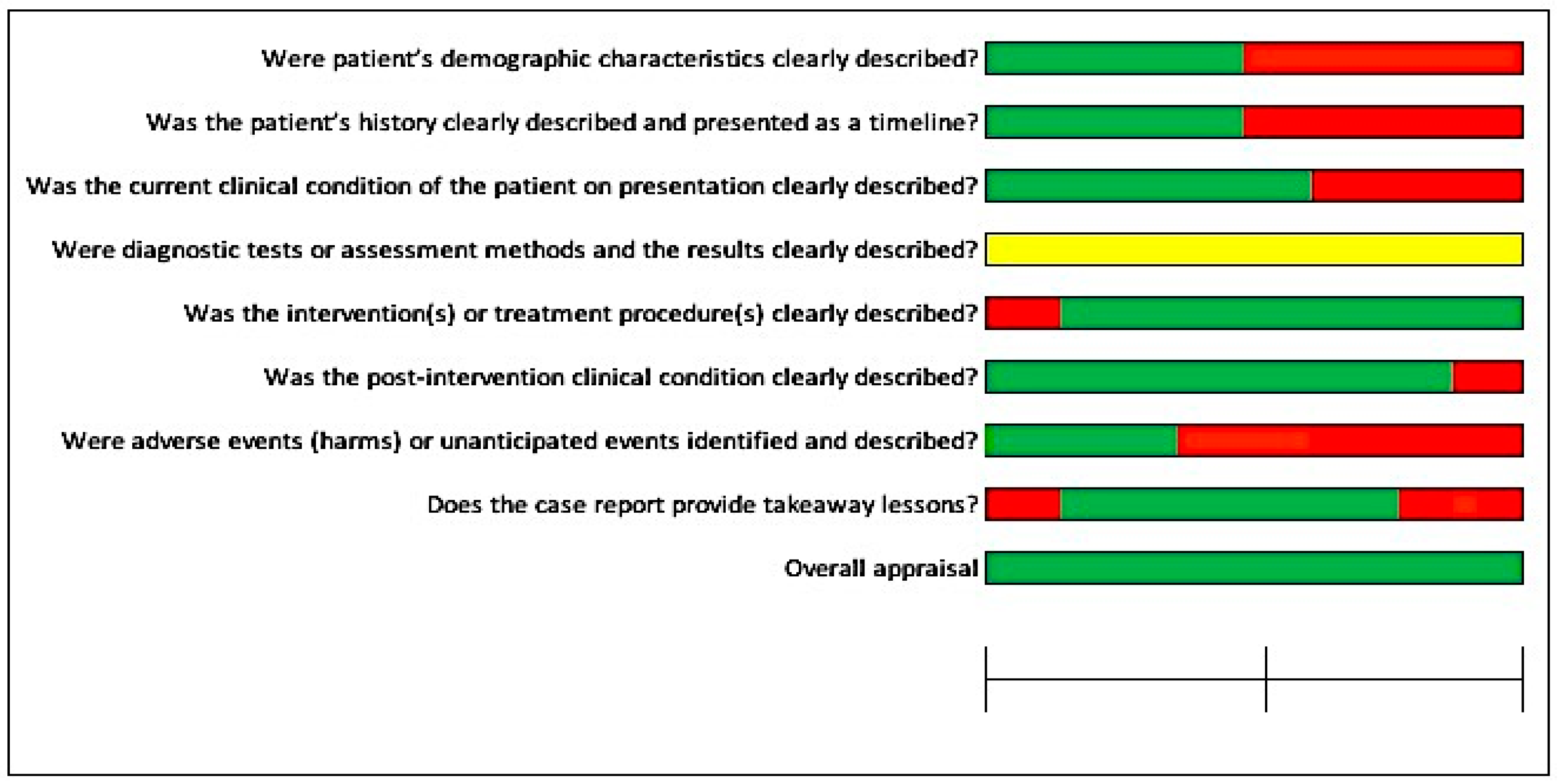
In Figure 2, most studies had a low risk of bias (≤50%), except for the specific question, “Were adverse events (harms) or unanticipated events identified and described?”, where more than 75% of the included studies had not mentioned any adverse events or unanticipated events. For another question, “Were the diagnostic tests or assessment methods and the results clearly described?”, more than 75% of the studies had not clearly mentioned the diagnostic tests, assessment methods, or results of the investigations.

Figure 2.
Risk of bias across the included studies for case reports.
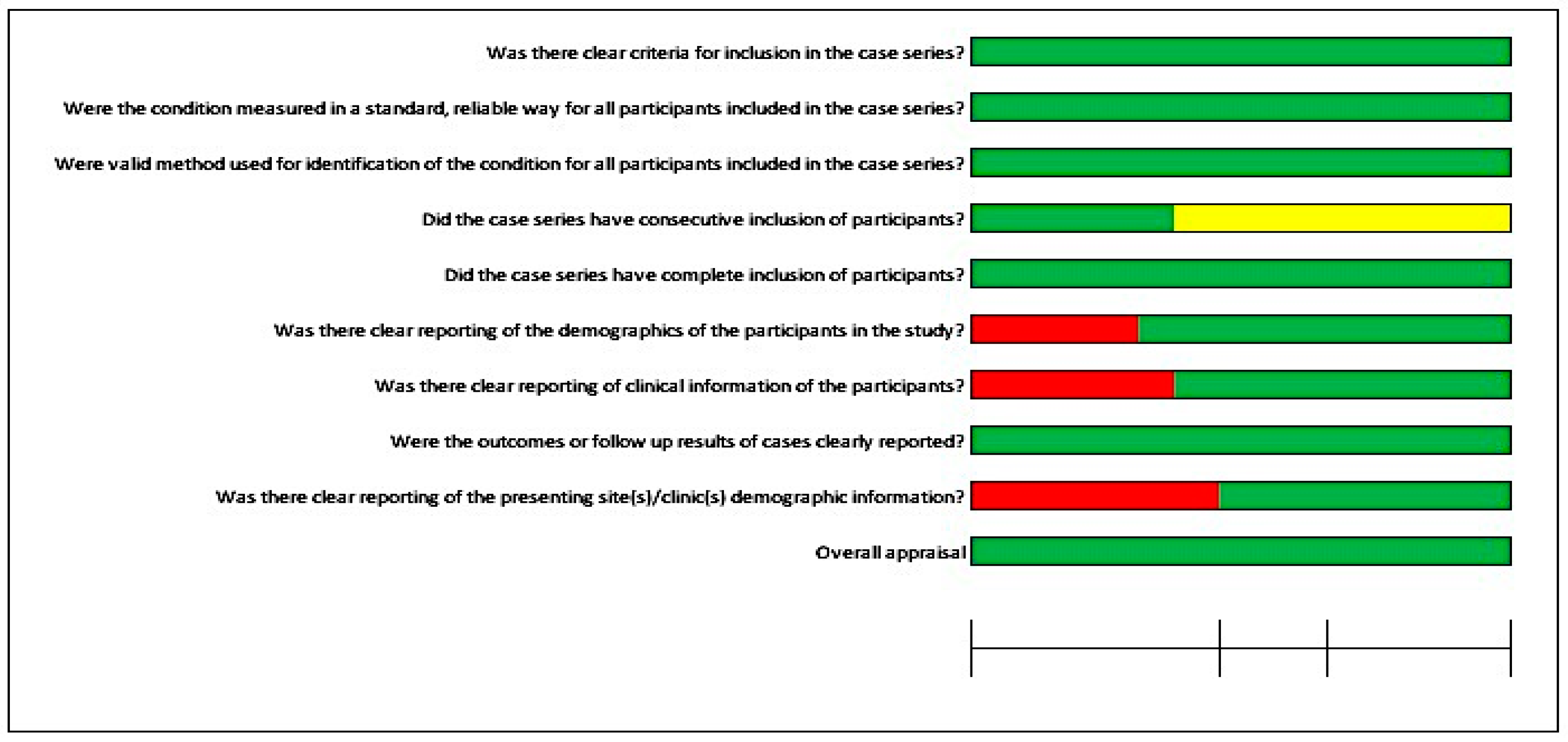
Furthermore, Figure 3 illustrates the risk of bias for four case series studies. Most questions were in favor of a low risk of bias. For two questions, the details were unclear: “Were valid methods used for identification of the condition for all participants included in the case series?” and “Was there clear reporting of clinical information of the participants?”. Furthermore, it was not possible to perform a meta-analysis due to the quality of the included studies, case series, and case reports.
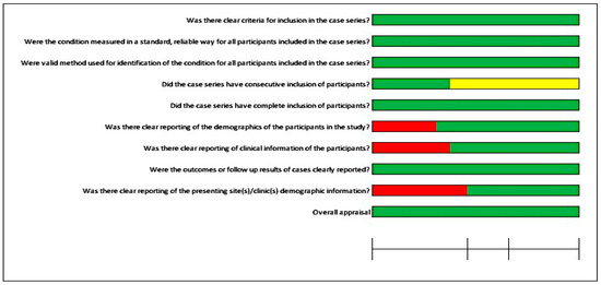
Figure 3.
Risk of bias for the case series.
4. Discussion
Digitally assisted design and digitally assisted manufacturing (CAD/CAM) systems have been utilized for the design and manufacturing of medical devices for the last couple of decades. The digital planning software were first utilized for intraoral implant placement in 1997 [59,60]. Further digital and technical advancements led clinicians and dental technologists to plan guided implant surgeries, the manufacturing of custom implants, retentive attachments, digital wax-ups, molds, and prostheses [61,62]. With the CAD/CAM applications, virtual surgical planning and its application in surgical procedures became more predictable, reduced the laboratory and clinical time for the procedures, reduced the patient’s appointments, and enabled the patients to virtually observe the proposed outcome prior to invasive procedures [61,62]. Various clinical case studies have documented the applications of digital technology for the fabrication of auricular prostheses; therefore, the aim of this paper was to gather the clinical studies involving the clinical and technical applications of CAD/CAM technology for craniofacial implant placement and the fabrication of auricular prostheses.
Three-dimensional imaging has added an extra dimension to the conventionally available preoperative radiographs, with the additional advantage of low radiation doses and detailed information about the bone quantity, bone volume, and proximity of adjacent critical anatomical structures [63,64]. The obtained data from computed tomography (CT), magnetic resonance imaging (MRI), or cone-beam computed tomography (CBCT) can be used in conjunction with digital planning software for preoperative planning [65,66]. The obtained data from tomographic images in combination with digital planning software help guide the implant placement in the optimum position and angulation according to the surgical and prosthetic plan [65,67]. Various factors such as tube current, slice thickness, voltage, pitch, the reconstruction algorithm for image slices, minor patient movement, and artifacts from metal objects can induce significant errors [68]. Among these factors, the slice thickness can influence the volume measurement, thus it should be set at <1.25 mm [68,69]. A total of seven included studies mentioned the slice thickness of CT scans ranging from 1 to 1.25 mm [28,34,35,37,40,44,49], while two included studies made use of a slice thickness less than 1 mm [31,50]. Furthermore, the voxel size affects the quality and reconstruction time of the CBCT images. None of the included clinical studies mentioned the voxel size.
The integration of 3D radiographic images and laser scans enabled the preoperative planning for guided implant surgeries. These two entities, when incorporated into the digital designing software, provided the possibility for maxillofacial surgeons and prosthodontists to plan the surgeries in chronological sequence (prosthesis-driven implant placement), from prosthetic design and position downwards to the implant position and angulation [70]. In this study, 77 cases were planned and executed by utilizing CT scans, CBCT scans, EBCT scans, MRIs, and laser scanners; however, only 14 cases were planned by the combined use of 3D radiographic images and laser scans for preoperative planning and designing of auricular prostheses.
Virtual planning has been mainly dependent on computer-aided design systems (CAD). These designing systems combine laser scans of intact and defect sides as well as 3D tomographic images to estimate the exact location and angulation of implants, to design the surgical templates, to plan and design the retentive attachments, and to design the molds, frameworks, customized implants, and provisional and definitive prostheses. In the current study, Meshmixer (Autodesk Inc., USA), Geomagics Studio software (3D Systems, Rock Hill, SC, USA), 3 Shape software (3 Shape, Copenhagen, Denmark), iPlan Cranial 3.0 BrainLAB software (BrainLAB AG, Munich, Germany), BrainLAB software (BrainLAB AG, Munich, Germany), Mimics Software (Mimics Innovation Suite, Materialise, Leuven, Belgium), Rapidform CAD software (INUS Technology, Seoul, South Korea), Rhinoceros Software v. 4.0 (Robert McNeel & Associates, USA), and Stryker iNtellect Cranial (Stryker Navigation system, MI, USA) were used in a total of 77 cases to plan and place 88 implants in auricular defects for prosthetic purposes. These implants were guided by surgical templates to be placed between 9 and 11 o’clock positions on the right side and between 1 and 3 o’clock positions on the left side, respectively [10]. Meanwhile, Z brush software (Pixologic, Inc., USA), Exocad software (Exocad, GmbH, Darmstadt, Germany), Geomagics Studio software (3D Systems, Rock Hill, SC, USA), Artec studio 16 software (Artec 3D, Luxembourg), Materialise 3-matic software 9.0 (Materalise, Leuven, Belgium), Freeform software (Freeform, NC, USA), NextEngine Scan studio software (NextEngine, CA, USA), Rapidworks 64 version 4.1.0. (3D system, Inc. Rock Hill, USA), Mimics Software (Mimics Innovation Suite, Materialise, Leuven, Belgium), and Polygone editing tool (Minolta Co, Osaka, Japan) designing software were used in 42 cases to design the scan bodies, customized implants, retentive attachments, models, molds, substructures for silicone auricular prostheses.
The computer-aided designing (CAD) step ultimately leads to the computer-aided manufacturing (CAM) step in order to convert the virtually planned and designed models, molds, templates, and prostheses to physical form by utilizing 3D printing systems [71,72,73]. Currently, six prototyping technologies can be used to convert virtually planned and designed objects into physical reality: stereolithography, laminated object manufacturing, selective laser sintering, solid ground curing, 3D ink-jet printing, and fused deposition modeling [36]. However, stereolithography (SLA), selective laser sintering (SLS), and fused deposition modeling (FDM) are the most frequently used 3D printing technologies. The FDM technology makes use of plastic filament, which is heated and extruded through the extrusion head onto the platform. As soon as extruded filament drops on the platform, it hardens due to the controlled temperature. In this way, layer-by-layer deposition builds up a physical model. To construct more complex models, multiple extrusion heads are required [73]. Plastics used for FDM technology are mainly acrylonitrile butyric styrene (ABS), polycarbonates, and polysulfides. The SLA technology utilizes ultraviolet light to polymerize the photosensitive resin. Following each layer of resin deposition on the platform, ultraviolet light cures successive layers, and photopolymerization helps to build up complex structures [73]. SLA-based printing technology utilizes a monomer resin that converts into a polymer upon photopolymerization. FDM printers are usually used to print models, molds, and provisional prostheses, while SLA printers are mainly used to print surgical templates for guided implant placement surgeries [74]. In the current review, SLA printing technology was used for 10 cases, SLS printers were used for 22 cases, and FDM printers were used for 40 cases. The most common printing materials were resin powders, polylactic acid (PLA), polyamide, titanium grade 2, gypsum powder, and ABS material.
Craniofacial implants were virtually planned for precise placement in the mastoid bone for the support and retention of auricular prostheses. A total of 88 implants were placed in right and left auricular defects in 35 cases following digital planning. Surgical templates and navigation systems were used to guide the implants in the planned locations. Due to various factors such as the anatomical morphology, radiation therapy, chemotherapy, and morphology of the tissue bed, two to four implants were placed in each auricular defect for prosthetic rehabilitation. Retention of auricular prostheses was mainly gained by clip bar and magnet attachments; however, locator attachment with a customized bone plate was also reported in one study [50]. Postoperative data to assess the accuracy of digitally planned extraoral implant placement for facial prosthetic rehabilitation are very limited [61,62]. Only one included study mentioned the postoperative accuracy of digitally planned auricular implant placement. Three implants had deviated by an average of 4.67 mm. However, the case was successfully rehabilitated by using an orientation guide for an auricular prosthesis [58].
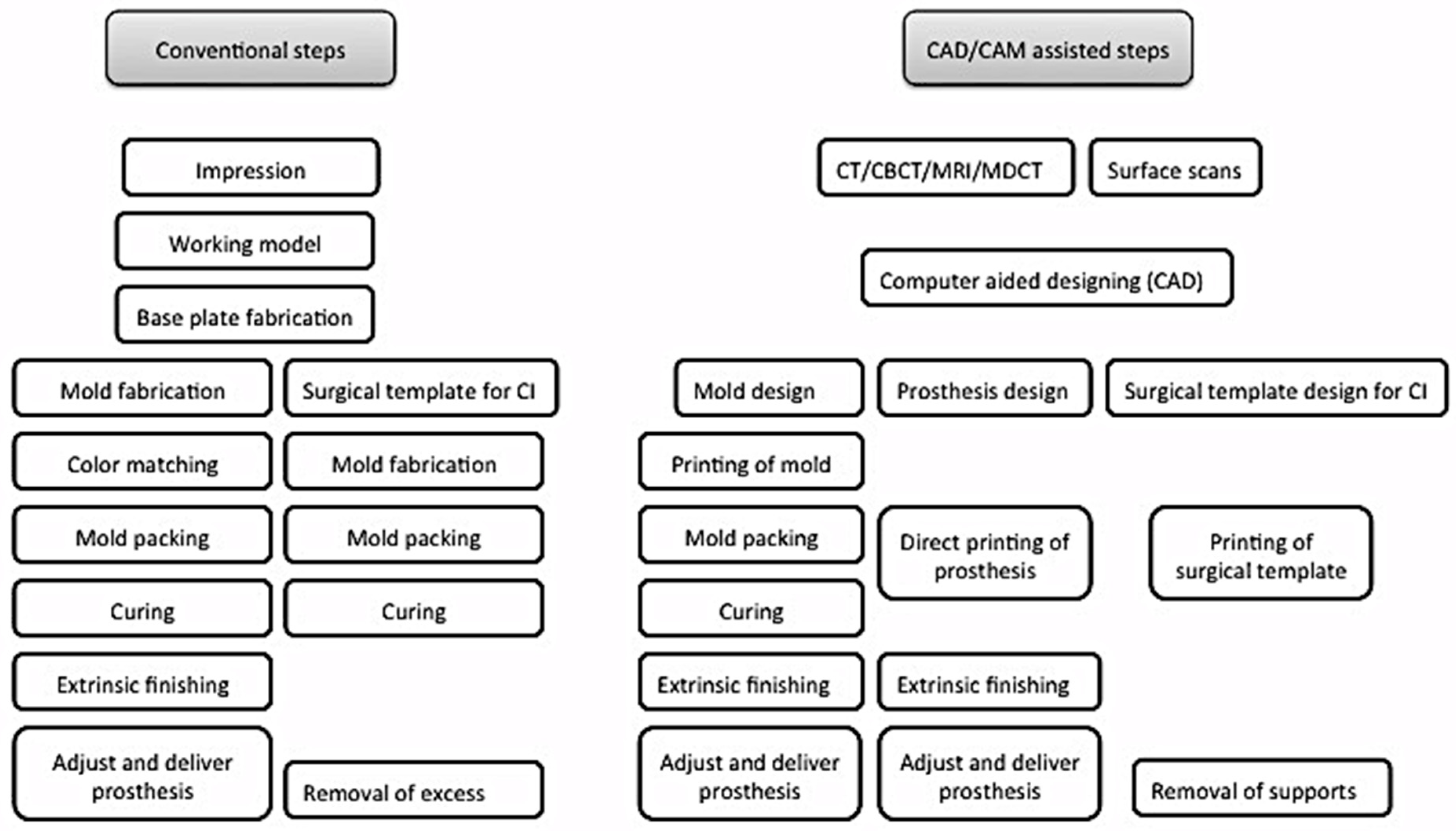
Digital planning and design systems have reduced the patient’s visits to a minimum of two to three visits. [29,33,40] Table 4. Furthermore the included studies showed satisfactory clinical outcome for the prosthetic rehabilitation of auricular defects (Table 5). Mirroring the intact ear to the defect side helps to obtain the digital model, which can be printed to replicate the ear wax pattern [27,28,29,32,33,40,41]. The time required to plan, design, and manufacture the wax pattern through CAD/CAM systems ranged from 40 min to 4 h, which if processed conventionally would require more than 6 h [27,41] (Table 4). The systematic reviews from Tanveer, W. et al. [61,62] further provided the expected time and cost for the digital workflow involved in the processing of facial prostheses for the readers to obtain a general overview of the time and cost involved in the digital planning, designing, and manufacturing of facial prostheses. Navigation systems have further paced the surgical planning and placement of implants. According to Verma et al., 2010 [22], the navigation system for guiding the craniofacial implants had reduced the clinical and laboratory time by 10 h. Additionally, digital workflow has enabled patients to visualize the proposed plan prior to invasive procedures, thereby giving the option to the patients to either accept or reject the proposed plan based on the expected outcome. Once the clinician and patient decide to proceed, the planning and designing software helps to construct surgical templates, models, molds, customized implants, retentive attachments, and even direct silicone prostheses (Figure 4).
Table 4.
Efficiency of digital workflow verses conventional processing of auricular prostheses.
Table 5.
Enlisted are the clinical outcomes, recommendations, and limitations mentioned in the included clinical studies.

Figure 4.
Comparison between conventional and digital planning and designing of surgical templates and prostheses fabrication.
The current systematic review includes clinical studies that were planned and executed from data acquisition to the virtual designing and printing of surgical templates, molds, substructures, implants, retentive attachments, and auricular prostheses. CAD/CAM systems have provided numerous advantages over conventional processing, such as predictability, reduced clinical and laboratory time, reduced patient visits, and the ability to view and discuss the end outcome before invasive procedures. However, studies about the accuracy of these digital planning software and printing systems are not yet available. Therefore, clinical trials are needed to assess the precision and accuracy of these CAD/CAM systems, especially for guided implant surgeries. Furthermore, the cost of equipment, maintenance, and trained technical staff pose limitations; therefore, these facilities are only accessible in high-end centers. Printing of color-matched prostheses, direct printing of prostheses with medical-grade silicone, and controlled fine thickness of the margins of prostheses are the other limitations that need to be addressed with further digital and technical advancements.
5. Conclusions
CAD/CAM systems have been used for maxillofacial prosthetics in the planning, designing, and manufacturing stages for the last couple of decades. Clinical and technical applications of CAD/CAM technology include data acquisition, planning and designing surgical templates, models, molds, retentive attachments, customized implants, and the manufacturing of prostheses. These CAD/CAM systems have shown a predictable clinical outcome, reduced the clinical and technical time to fabricate auricular prostheses, and reduced the patient’s appointments when compared to conventional processing techniques. However, the availability of trained technical staff and the equipment cost limit the use of CAD/CAM in most parts of the world. Despite the digital advancements, direct printing of silicone auricular prostheses, production of featheredge thin margins, and direct printing of color-matched prostheses are the few current limitations of CAD/CAM-assisted techniques that need to be addressed. Furthermore, human clinical trials are needed to determine the precision and accuracy of these CAD/CAM systems for craniofacial implant placement and the fabrication of auricular prostheses.
Author Contributions
Conceptualization, W.T., A.R.-P. and T.F.; methodology, W.T., A.R.-P. and T.F.; validation, W.T., A.R.-P. and T.F.; formal analysis, W.T. and P.M.-M.; resources, W.T. and P.M.-M.; writing—original draft preparation, W.T.; writing—review and editing, W.T.; supervision, A.R.-P. and T.F. All authors have read and agreed to the published version of the manuscript.
Funding
This research received no external funding.
Institutional Review Board Statement
Ethical review and approval were waived for this study due to the retrospective data, which were readily available through published papers. Therefore, no direct human or animal contact was involved in gathering these data.
Informed Consent Statement
Not applicable for this systematic review.
Data Availability Statement
Not applicable for this systematic review.
Conflicts of Interest
The authors declare no conflict of interest.
References
- Nishimura, R.D.; Roumanas, E.; Sugai, T.; Moy, P.K. Auricular prostheses and osseointegrated implants: UCLA experience. J. Prosthet. Dent. 1995, 73, 553–558. [Google Scholar] [CrossRef] [PubMed]
- Guo, G.; Schwedtner, O.; Klein, M. A retrospective study of implant-retained auricular prostheses. Int. J. Oral Maxillofac. Implant. 2008, 23, 539–543. [Google Scholar]
- Visser, A.; Raghoebar, G.M.; Van Oort, R.P.; Vissink, A. Fate of implant-retained craniofacial prostheses: Life span and aftercare. Int. J. Oral Maxillofac. Implant. 2008, 23, 89–98. [Google Scholar]
- Aydin, C.; Karakoca, S.; Yilmaz, H.; Yilmaz, C. Implant-retained auricular prostheses: An assessment of implant success and prosthetic complications. Int. J. Prosthodont. 2008, 21, 241–244. [Google Scholar] [PubMed]
- Brent, B. Auricular repair with autogenous rib cartilage grafts: Two decades of experience with 600 cases. Plast Reconstr. Surg. 1992, 90, 355–374. [Google Scholar] [CrossRef] [PubMed]
- Tanzer, R.C. Total reconstruction of the external ear. Plast. Reconstr. Surg. Transplant Bull. 1959, 23, 1–15. [Google Scholar] [CrossRef]
- Thorne, C.H.M.; Brecht, L.E.D.; Bradley, J.P.M.; Levine, J.P.M.; Hammerschlag, P.M.; Longaker, M.T.M. Auricular Reconstruction: Indications for Autogenous and Prosthetic Techniques. Plast. Reconstr. Surg. 2001, 107, 1241–1251. [Google Scholar] [CrossRef]
- Tam, C.K.; McGrath, C.P.; Ho, S.M.Y.; Pow, E.H.N.; Luk, H.W.K.; Cheung, L.K. Psychosocial and Quality of Life Outcomes of Prosthetic Auricular Rehabilitation with CAD/CAM Technology. Int. J. Dent. 2014, 2014, 393571. [Google Scholar] [CrossRef]
- Gumieiro, E.H.; Dib, L.L.; Jahn, R.S.; Junior, J.F.d.S.; Nannmark, U.; Granström, G.; Abrahão, M. Bone-anchored titanium implants for auricular rehabilitation: Case report and review of literature. Sao Paulo Med. J. 2009, 127, 160–165. [Google Scholar] [CrossRef]
- Girod, S.C.; Rohlfing, T.; Maurer, C.R. Image-Guided Surgical Navigation in Implant-Based Auricular Reconstruction. J. Oral Maxillofac. Surg. 2008, 66, 1302–1306. [Google Scholar] [CrossRef]
- Williams, B.H.; Ochiai, K.T.; Baba, T.; A Caputo, A. Retention and load transfer characteristics of implant-retained auricular prostheses. Int. J. Oral Maxillofac. Implant. 2007, 22, 366–372. [Google Scholar]
- Lemon, J.C.; Chambers, M.S. Locking retentive attachment for an implant-retained auricular prosthesis. J. Prosthet. Dent. 2002, 87, 336–338. [Google Scholar] [CrossRef] [PubMed]
- Waqas, T.S.; Shrestha, B.; Srithavaj, M.L.T.; Chotprasert, N. A two-step functional impression technique for the fabrication of an implant-retained silicone auricular prosthesis. J. Prosthet. Dent. 2017, 117, 444–447. [Google Scholar] [CrossRef] [PubMed]
- Van Der Meer, W.J.; Vissink, A.; Raghoebar, G.M.; Visser, A. Digitally designed surgical guides for placing extraoral implants in the mastoid area. Int. J. Oral Maxillofac. Implant. 2012, 27, 703–707. [Google Scholar]
- Datarkar, A.; Daware, S.; Dande, R.; Datarkar, U. Rehabilitation of unilateral congenital microtia by implant-retained prosthesis. Ann. Maxillofac. Surg. 2017, 7, 291–295. [Google Scholar] [CrossRef] [PubMed]
- Ballo, A.M.; Nguyen, C.T.; Lee, V.S. Digital Workflow of Auricular Rehabilitation: A Technical Report Using an Intraoral Scanner. J. Prosthodont. 2019, 28, 596–600. [Google Scholar] [CrossRef]
- Kurtulmus, H.; Cotert, H.S.; Guneri, P. Computed tomography-based planning and three-dimensional modeling for craniofacial implant placement: A technical note. Int. J. Oral Maxillofac. Implant. 2009, 24, 943–946. [Google Scholar]
- Elbashti, M.; Sumita, Y.; Kelimu, S.; Aswehlee, A.; Awuti, S.; Hattori, M.; Taniguchi, H. Application of Digital Technologies in Maxillofacial Prosthetics Literature: A 10-Year Observation of Five Selected Prosthodontics Journals. Int. J. Prosthodont. 2019, 32, 45–50. [Google Scholar] [CrossRef]
- Kernen, F.; Kramer, J.; Wanner, L.; Wismeijer, D.; Nelson, K.; Flügge, T. A review of virtual planning software for guided implant surgery—Data import and visualization, drill guide design and manufacturing. BMC Oral Health 2020, 20, 251. [Google Scholar] [CrossRef]
- Ciocca, L.; Scotti, R. Oculo-facial rehabilitation after facial cancer removal: Updated CAD/CAM procedures: A pilot study. Prosthet. Orthot. Int. 2014, 38, 505–509. [Google Scholar] [CrossRef]
- Liu, H.; Bai, S.; Yu, X.; Zhao, Y. Combined use of a facial scanner and an intraoral scanner to acquire a digital scan for the fabrication of an orbital prosthesis. J. Prosthet. Dent. 2019, 121, 531–534. [Google Scholar] [CrossRef] [PubMed]
- Verma, S.N.; Schow, S.R.; Stone, B.H.; Triplett, R.G. Applications of surgical navigational systems for craniofacial bone-anchored implant placement. Int. J. Oral Maxillofac. Implants 2010, 25, 582–588. [Google Scholar] [PubMed]
- Nuseir, A.; Hatamleh, M.M.; Alnazzawi, A.; Al-Rabab’Ah, M.; Kamel, B.; Jaradat, E. Direct 3D Printing of Flexible Nasal Prosthesis: Optimized Digital Workflow from Scan to Fit. J. Prosthodont. 2019, 28, 10–14. [Google Scholar] [CrossRef]
- Moher DL, A.; Tetzlaff, J.; Altman, D.G. Preferred reporting items for systematic reviews and meta-analyses: The PRISMA statement. PLoS Med. 2009, 6, e1000097. [Google Scholar] [CrossRef] [PubMed]
- Moola SA, E.; Sears, K.; Sfetcu, R.; Currie, M.; Lisy, K.; Qureshi, R.; Mattis, P.; Mu, P. Chapter 7: Systematic reviews of etiology and risk. In Joanna Briggs Institute Reviewer’s Manual; Aromataris, E., Munn, Z., Eds.; JBI: Adelaide, Australia, 2017. [Google Scholar] [CrossRef]
- Ciocca, L.; Scotti, R. CAD-CAM generated ear cast by means of a laser scanner and rapid prototyping machine. J. Prosthet. Dent. 2004, 92, 591–595. [Google Scholar] [CrossRef] [PubMed]
- Sykes, L.M.; Parrott, A.M.; Owen, C.P.; Snaddon, D.R. Applications of rapid prototyping technology in maxillofacial prosthetics. Int. J. Prosthodont. 2004, 17, 454–459. [Google Scholar] [PubMed]
- Jiao, T.; Zhang, F.; Huang, X.; Wang, C. Design and fabrication of auricular prostheses by CAD/CAM system. Int. J. Prosthodont. 2004, 17, 460–463. [Google Scholar] [PubMed]
- Ciocca, L.; Mingucci, R.; Gassino, G.; Scotti, R. CAD/CAM ear model and virtual construction of the mold. J. Prosthet. Dent. 2007, 98, 339–343. [Google Scholar] [CrossRef]
- Ciocca, L.; Mingucci, R.; Bacci, G.; Scotti, R. CAD-CAM construction of an auricular template for craniofacial implant positioning: A novel approach to diagnosis. Eur. J. Radiol. 2009, 71, 253–256. [Google Scholar] [CrossRef]
- Turgut, G.; Sacak, B.; Kiran, K.; Bas, L. Use of rapid prototyping in prosthetic auricular restoration. J. Craniofac. Surg. 2009, 20, 321–325. [Google Scholar] [CrossRef]
- Ciocca, L.; De Crescenzio, F.; Fantini, M.; Scotti, R. CAD/CAM bilateral ear prostheses construction for Treacher Collins syndrome patients using laser scanning and rapid prototyping. Comput. Methods Biomech. Biomed. Engin. 2010, 13, 379–386. [Google Scholar] [CrossRef]
- De Crescenzio, F.; Fantini, M.; Ciocca, L.; Persiani, F.; Scotti, R. Design and manufacturing of ear prosthesis by means of rapid prototyping technology. Proc. Inst. Mech. Eng. H. 2011, 225, 296–302. [Google Scholar] [PubMed]
- Liacouras, P.; Garnes, J.; Roman, N.; Petrich, A.; Grant, G.T. Designing and manufacturing an auricular prosthesis using computed tomography, 3-dimensional photographic imaging, and additive manufacturing: A clinical report. J. Prosthet. Dent. 2011, 105, 78–82. [Google Scholar] [CrossRef]
- Kolodney, H., Jr.; Swedenburg, G.; Taylor, S.S.; Carron, J.D.; Schlakman, B.N. The use of cephalometric landmarks with 3-dimensional volumetric computer modeling to position an auricular implant surgical template: A clinical report. J. Prosthet. Dent. 2011, 106, 284–289. [Google Scholar] [CrossRef] [PubMed]
- Karatas, M.O.; Cifter, E.D.; Ozenen, D.O.; Balik, A.; Tuncer, E.B. Manufacturing implant supported auricular prostheses by rapid prototyping techniques. Eur. J. Dent. 2011, 5, 472–477. [Google Scholar] [CrossRef] [PubMed]
- Bai, S.; Bi, Y.; Dong, Y.; Feng, Z.; Zhao, Y. Computer-aided design/computer-aided manufacturing implant guide used in flapless surgery for auricular prosthesis. J. Oral Maxillofac. Surg. 2012, 70, 1338–1341. [Google Scholar] [CrossRef] [PubMed]
- Reitemeier, B.; Schöne, C.; Schreiber, S.; Stockmann, F.; Ullmann, K.; Eckelt, U. Planning implant positions for an auricular prosthesis with digital data. J. Prosthet. Dent. 2012, 107, 128–131. [Google Scholar] [CrossRef]
- Hatamleh, M.M.; Watson, J. Construction of an implant-retained auricular prosthesis with the aid of contemporary digital technologies: A clinical report. J. Prosthodont. 2013, 22, 132–136. [Google Scholar] [CrossRef]
- Bai, S.-Z.; Feng, Z.-H.; Gao, R.; Dong, Y.; Bi, Y.-P.; Wu, G.-F.; Chen, X. Development and application of a rapid rehabilitation system for reconstruction of maxillofacial soft-tissue defects related to war and traumatic injuries. Mil. Med. Res. 2014, 1, 11. [Google Scholar] [CrossRef]
- Watson, J.; Hatamleh, M.M. Complete integration of technology for improved reproduction of auricular prostheses. J. Prosthet. Dent. 2014, 111, 430–436. [Google Scholar] [CrossRef]
- Wang, S.; Leng, X.; Zheng, Y.; Zhang, D.; Wu, G. Prosthesis-guided implant restoration of an auricular defect using computed tomography and 3-dimensional photographic imaging technologies: A clinical report. J. Prosthet. Dent. 2015, 113, 152–156. [Google Scholar] [CrossRef] [PubMed]
- Nuseir, A.; Hatamleh, M.; Watson, J.; Al-Wahadni, A.M.; Alzoubi, F.; Murad, M. Improved Construction of Auricular Prosthesis by Digital Technologies. J. Craniofac. Surg. 2015, 26, e502–e505. [Google Scholar] [CrossRef]
- Choi, K.J.; Sajisevi, M.B.; McClennen, J.; Kaylie, D.M. Image-Guided Placement of Osseointegrated Implants for Challenging Auricular, Orbital, and Rhinectomy Defects. Ann. Otol. Rhinol. Laryngol. 2016, 125, 801–807. [Google Scholar] [CrossRef]
- Weissler, J.M.; Sosin, M.; Dorafshar, A.H.; Garcia, J.R. Combining Virtual Surgical Planning, Intraoperative Navigation, and 3-Dimensional Printing in Prosthetic-Based Bilateral Microtia Reconstruction. J. Oral. Maxillofac. Surg. 2017, 75, 1491–1497. [Google Scholar] [CrossRef] [PubMed]
- Yadav, S.; Narayan, A.I.; Choudhry, A.; Balakrishnan, D. CAD/CAM-Assisted Auricular Prosthesis Fabrication for a Quick, Precise, and More Retentive Outcome: A Clinical Report. J. Prosthodont. 2017, 26, 616–621. [Google Scholar] [CrossRef]
- Jamayet, N.B.; Abdullah, J.Y.; Rahman, A.M.; Husein, A.; Alam, M.K. A fast and improved method of rapid prototyping for ear prosthesis using portable 3D laser scanner. J. Plast. Reconstr. Esthet. Surg. 2018, 71, 946–953. [Google Scholar] [CrossRef]
- Unkovskiy, A.; Brom, J.; Huettig, F.; Keutel, C. Auricular Prostheses Produced by Means of Conventional and Digital Workflows: A Clinical Report on Esthetic Outcomes. Int. J. Prosthodont. 2018, 31, 63–66. [Google Scholar] [CrossRef]
- Sanghavi, R.V.; Shingote, S.D.; Abhang, T.N.; Thorat, P.R.; Vathare, A.S. An innovative technique for fabricating a mirror image wax pattern using three-dimensional printing technology for an auricular prosthesis. J. Res. Dent. Sci. 2018, 9, 91. [Google Scholar] [CrossRef]
- Ferreira, R.; Vives, P. Two auricular epithesis surgical cases retained by a custom titanium implant: Result at four years. J. Stomatol. Oral Maxillofac. Surg. 2019, 120, 147–151. [Google Scholar] [CrossRef]
- Vijverberg, M.A.; Verhamme, L.; van de Pol, P.; Kunst, H.P.M.; Mylanus, E.A.M.; Hol, M.K.S. Auricular prostheses attached to osseointegrated implants: Multidisciplinary work-up and clinical evaluation. Eur. Arch. Otorhinolaryngol. 2019, 276, 1017–1027. [Google Scholar] [CrossRef]
- Cevik, P.; Kocacikli, M. Three-dimensional printing technologies in the fabrication of maxillofacial prosthesis: A case report. Int. J. Artif. Organs. 2020, 43, 343–347. [Google Scholar] [CrossRef]
- McHutchion, L.; Aalto, D. Simulation of tissue-prosthesis margin interface by using surface scanning and digital design for auricular prostheses. J. Prosthet. Dent. 2021, 125, 361–372. [Google Scholar] [CrossRef]
- Domingue, D.; Glenn, N.C.; Vest, A.; White, J.R. Osseointegrated implant-retained auricular prosthesis constructed using cone-beam computed tomography and a prosthetically driven digital workflow: A case report. Clin. Case Rep. 2021, 9, 37–45. [Google Scholar] [CrossRef]
- Unkovskiy, A.; Wahl, E.; Huettig, F.; Keutel, C.; Spintzyk, S. Multimaterial 3D printing of a definitive silicone auricular prosthesis: An improved technique. J. Prosthet. Dent. 2021, 125, 946–950. [Google Scholar] [CrossRef]
- Dashti, H.; Rajati Haghi, H.; Nakhaei, M.; Kiamanesh, E. A combined digital technique to fabricate an implant-retained auricular prosthesis for rehabilitation of hemifacial microsomia. J. Prosthet. Dent. 2022, 127, 807–810. [Google Scholar] [CrossRef]
- Hatamleh, M.M.; Watson, J.; Nuseir, A. Successful prosthetic salvage of a suboptimal autogenous auricular reconstruction with digital technologies: A report of 3 challenging treatments. J. Prosthet. Dent. 2022, 128, 1103–1108. [Google Scholar] [CrossRef] [PubMed]
- Heydenrych, A.; van der Walt, J.G.; van den Heever, H.J. Auricular prosthesis positioning using virtual planning in combination with additive manufacturing. J. Stomatol. Oral Maxillofac. Surg. 2023, 124, 101258. [Google Scholar] [CrossRef] [PubMed]
- Ewers, R.; Schicho, K.; Truppe, M.; Seemann, R.; Reichwein, A.; Figl, M.; Wagner, A. Computer-aided navigation in dental implantology: 7 years of clinical experience. J. Oral Maxillofac. Surg. 2004, 62, 329–334. [Google Scholar] [CrossRef]
- Mupparapu, M.; Singer, S.R. Implant imaging for the dentist. J. Can. Dent. Assoc. 2004, 70, 32. [Google Scholar] [PubMed]
- Tanveer, W.; Ridwan-Pramana, A.; Molinero-Mourelle, P.; Koolstra, J.H.; Forouzanfar, T. Systematic Review of Clinical Applications of CAD/CAM Technology for Craniofacial Implants Placement and Manufacturing of Nasal Prostheses. Int. J. Environ. Res. Public Health 2021, 18, 3756. [Google Scholar] [CrossRef]
- Tanveer, W.; Ridwan-Pramana, A.; Molinero-Mourelle, P.; Forouzanfar, T. Systematic Review of Clinical Applications of CAD/CAM Technology for Craniofacial Implants Placement and Manufacturing of Orbital Prostheses. Int. J. Environ. Res. Public Health 2021, 18, 11349. [Google Scholar] [CrossRef]
- Tahmaseb, A.; Wismeijer, D.; Coucke, W.; Derksen, W. Computer technology applications in surgical implant dentistry: A systematic review. Int. J. Oral Maxillofac. Implant. 2014, 29, 25–42. [Google Scholar] [CrossRef]
- Jacobs, R.; Adriansens, A.; Verstreken, K.; Suetens, P.; van Steenberghe, D. Predictability of a three-dimensional planning system for oral implant surgery. Dentomaxillofac. Radiol. 1999, 28, 105–111. [Google Scholar] [CrossRef]
- Israelson, H.; Plemons, J.M.; Watkins, P.; Sory, C. Barium-coated surgical stents and computer-assisted tomography in the preoperative assessment of dental implant patients. Int. J. Periodontics Restor. Dent. 1992, 12, 52–61. [Google Scholar]
- Basten, C.H. The use of radiopaque templates for predictable implant placement. Quintessence Int. 1995, 26, 609–612. [Google Scholar]
- Mizrahi, B.; Thunthy, K.H.; Finger, I. Radiographic/surgical template incorporating metal telescopic tubes for accurate implant placement. Pract. Periodontics Aesthet. Dent. 1998, 10, 757–765. [Google Scholar]
- Whyms, B.J.; Vorperian, H.K.; Gentry, L.R.; Schimek, E.M.; Bersu, E.T.; Chung, M.K. The effect of computed tomographic scanner parameters and 3-dimensional volume rendering techniques on the accuracy of linear, angular, and volumetric measurements of the mandible. Oral Surg. Oral Med. Oral Pathol. Oral Radiol. Endod. 2013, 115, 682–691. [Google Scholar] [CrossRef]
- Taft, R.M.; Kondor, S.; Grant, G.T. Accuracy of rapid prototype models for head and neck reconstruction. J. Prosthet. Dent. 2011, 106, 399–408. [Google Scholar] [CrossRef] [PubMed]
- Alauddin, M.S.; Baharuddin, A.S.; Mohd Ghazali, M.I. The Modern and Digital Transformation of Oral Health Care: A Mini Review. Healthcare 2021, 9, 118. [Google Scholar] [CrossRef] [PubMed]
- Ishida, Y.; Miura, D.; Miyasaka, T.; Shinya, A. Dimensional Accuracy of Dental Casting Patterns Fabricated Using Consumer 3D Printers. Polymers 2020, 12, 2244. [Google Scholar] [CrossRef] [PubMed]
- Dawood, A.; Marti Marti, B.; Sauret-Jackson, V.; Darwood, A. 3D printing in dentistry. Br. Dent. J. 2015, 219, 521–529. [Google Scholar] [CrossRef] [PubMed]
- Stansbury, J.W.; Idacavage, M.J. 3D printing with polymers: Challenges among expanding options and opportunities. Dent. Mater. 2016, 32, 54–64. [Google Scholar] [CrossRef] [PubMed]
- Nayar, S.; Bhuminathan, S.; Bhat, W.M. Rapid prototyping and stereolithography in dentistry. J. Pharm. Bioallied Sci. 2015, 7 (Suppl. 1), S216–S219. [Google Scholar] [CrossRef] [PubMed]
Disclaimer/Publisher’s Note: The statements, opinions and data contained in all publications are solely those of the individual author(s) and contributor(s) and not of MDPI and/or the editor(s). MDPI and/or the editor(s) disclaim responsibility for any injury to people or property resulting from any ideas, methods, instructions or products referred to in the content. |
© 2023 by the authors. Licensee MDPI, Basel, Switzerland. This article is an open access article distributed under the terms and conditions of the Creative Commons Attribution (CC BY) license (https://creativecommons.org/licenses/by/4.0/).