Article

Parameterisation and Optimisation of a Hand-Rake Sweeper: Application in Olive Picking

by
Rafael E. Hidalgo Fernández
1,
Pilar Carranza-Cañadas
1,
Francisco J. García-Salcedo
2 and
Paula Triviño-Tarradas
1,*
1
Department of Graphic Engineering and Geomatics, University of Cordoba, Campus de Rabanales, 14071 Córdoba, Spain
2
Independent Scholar, Cordoba, Spain
*
Author to whom correspondence should be addressed.
Agriculture 2020, 10(9), 379; https://doi.org/10.3390/agriculture10090379
Submission received: 29 July 2020 / Revised: 7 August 2020 / Accepted: 20 August 2020 / Published: 28 August 2020

Abstract

:
Olive picking is one of the most common social agricultural activities in many regions of Andalusia where the predominant crop is the traditional olive grove. The machinery used includes shakers, blowers and essential, low-cost hand-rake sweepers. The latter are generally used by the women of the squads to sweep the olives that fall from the trees. This article is focused on the design and optimisation of a hand-rake sweeper, in terms of durability and cost, for the picking of olives and other fruits, such as almonds, which are currently the main alternative to nonperennial crops in Andalusia. A parametric design of a hand-rake sweeper was created for this application using the design software CATIA, and its most vulnerable points were analysed in terms of effectiveness with varying design parameters, conducting usage simulations with ANSYS for a light material such as polypropylene. The maximum von Mises stress of the whole structure was 155.81 MPa. Using ANSYS, the dimension parameters of the hand-rake sweeper structure were optimised. The modified design was analysed again, showing a reduction of maximum tensions of 10.06%, as well as a decrease in its maximum elongations (0.0181 mm).

1. Introduction

Olives are one of the most important crops in the Mediterranean region [1], and therefore in Andalusia, occupying 47.24% of its cultivated surface area [2,3]; in fact, in some regions this is the only crop grown. It is also one of the most social crops [4], especially during the harvest when the workforce employed is the most significant expense, with an average of 13.83 workers per ha [2]. Picking represents 54.27% of the total work required for the olive grove [5,6]. It is a job performed mostly by men, although women play a relevant role in the lighter tasks [7]. The machinery used includes manual shakers for branches, shakers coupled to the tractor’s power take-off for the tree trunks, blowers and bale pickers. On the other hand, there are other lightweight tools, such as rods and hand-rake sweepers, which are used by part of the squad [7]. The latter are normally used by women to pile the olives that fall from the trees and facilitate their collection, preventing them from getting covered in dirt, which does not occur when carrying out this task using blowers [7].
Another crop, currently competing with the olive grove in the semiarid Mediterranean regions due to their profitability, is the almond [8]. Its harvest, although very mechanised, also poses a high cost due to the number of wages required [9,10]. In such harvesting process, the use of the hand-rake sweeper is of special relevance [11]. The cost and durability of these rakes is an important expense to take into account, since they tend to break easily and, thus, they must be replaced very often. The aim of this paper is to obtain the parameterised design and subsequent optimisation of a hand-rake sweeper, considering both the strains it can withstand and its cost. With the parameterisation of the hand-rake sweeper, it will be possible to simulate particular conditions, such as the different materials with which it can be manufactured and its use, depending on the different olive varieties. In addition, this will also allow extrapolating the application of this new tool to the harvest of other products, such as almonds.

2. Materials and Methods

2.1. Study Object

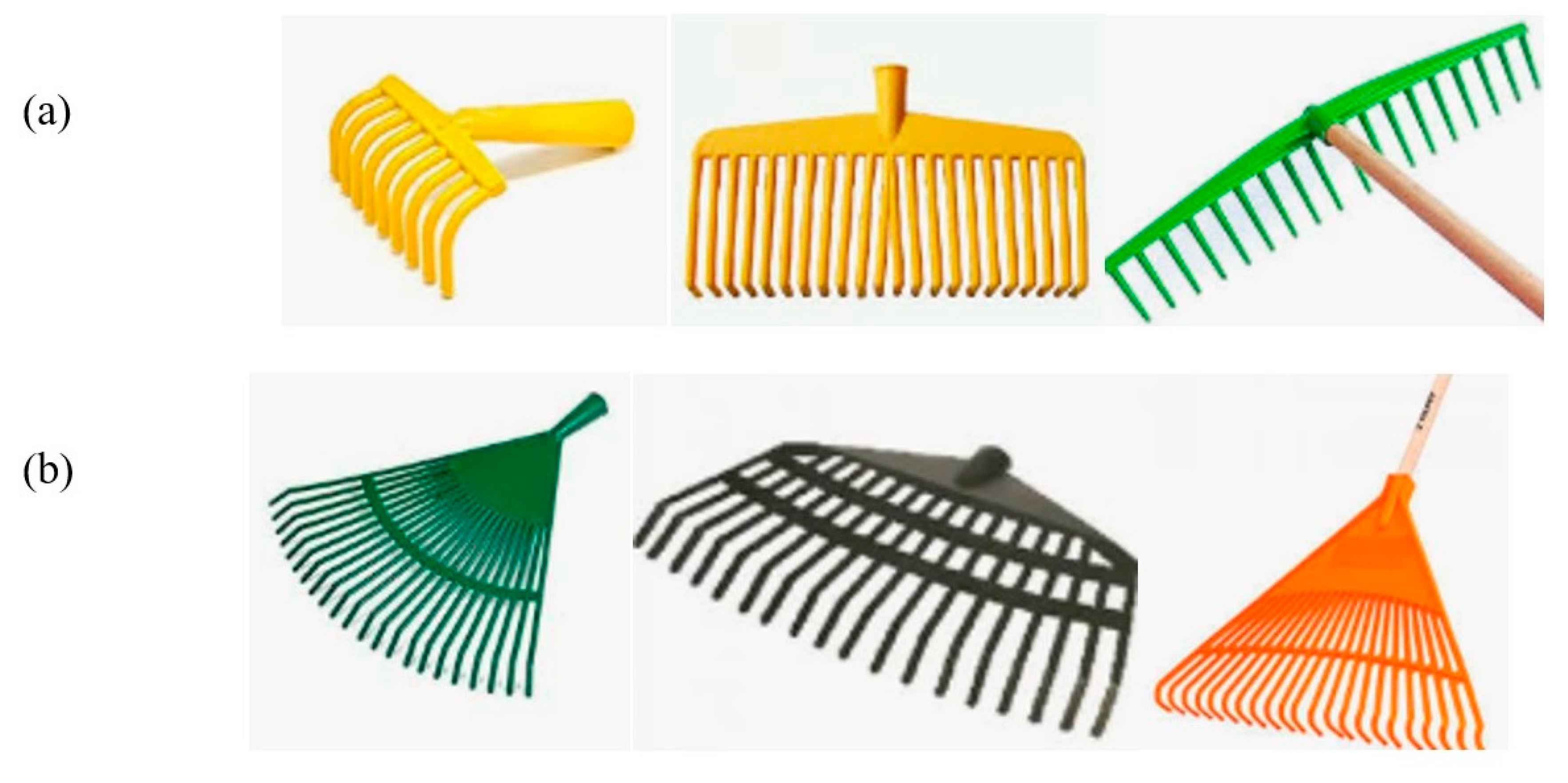
The hand-rake sweeper consists of one arm, traditionally made of wood (although nowadays it is usually made of metal), and a base of teeth or spikes, which were traditionally made of metal and are currently being replaced with plastic. Figure 1 shows some of the rakes that are commercialised these days: rectangular rakes (Figure 1a), which are formed with a directrix that sets all the teeth with the arm; and triangular rakes (Figure 1b), which open like a hand, fan up to the length of the sweep, with transversal teeth that hold the main teeth/spikes together. The shapes of this base have changed, with triangular and geometric shapes being the most widely used nowadays.
The work applied by the rake during its use can be described as an action of thrust against the ground, plus a drag-in action (Figure 2). This operation is analysed using the structural “strut-and-tie” model [12]. Such a model consists in discretising a system of internal strains that shows compression and traction lines. This helps to separately “study” the functioning of each part of the target instrument to be analysed. Figure 2 shows these traction and compression lines. The rake works by compression and dragging. The compression, that is, the “push” toward the ground, is transmitted through the handle of the rake, which works as a connecting rod, whereas its ends, which are resistant elements that transmit the force toward the ground, act as tie rods (Figure 3) [12].
The rake parameterised and analysed in this study is triangular, and the material used for its manufacture was polypropylene since it is currently the most widely used material. The rake is fabricated by the injection of molten plastic in a steel mould. Some advantages of using plastic are related to production, in addition to other reasons, such as being environmentally friendly [13], since plastic materials require lower energy consumptions for their manufacture. Moreover, they also show advantages in terms of durability, since plastic packages are practically unbreakable, which prevents spilling or damage to the food products, and in terms of hygiene, as they do not rust. For the design of the rake, polypropylene and wood were chosen for the base of the body and the handle, respectively. A parametric design was developed using the CATIA software.

2.2. Parametric Design of the Rake

A parametric design was developed using the CATIA software. Since it is a relatively flat object, without stiffeners, there will be a low risk of undesired shrinkages and manufacturing defects derived from contractions during solidification [14]. For the parameterisation of the rake, it was considered to be solid inside. To observe the behaviour of each of the elements that make up the rake, the “strut-and-tie” model was used, which is based on the theory of plasticity. This theory states that materials have a plastic-rigid behaviour, and that they only deform when they reach a certain tension, from which they keep deforming with no tension increase. Similarly, the body of the rake has a piece in its upper part where the handle is inserted. Such insertion of the handle in the main body of the rake must be adapted to achieve a correct functioning, after applying the necessary tensions to the body of the rake. There is a hole in the front side to screw the wooden handle and keep it fixed to the rake.
The next part is flat, in order to transmit the push and compression tensions from the handle, where the strain is applied down to the teeth/spikes. The teeth cannot be placed directly at the level of the handle, since a space of around 45° is required to allow for the correct action of the connecting rod. This design is based on models that are already in the market. Applying the “strut-and-tie” model, a compression direction of 45° from the handle to the teeth/spikes was designed. The brand or commercial identity of the rake does not have a mould release (draft) since it is 0.3 mm thick and it was thus considered unnecessary. The next area in the parametric design is the teeth of the rake, which expand to the final zone, where they are curved.
In the design, a certain tooth-to-tooth distance was set according to the objects to be swept, i.e., olives in this case, which could vary depending on the olive variety or the type of fruit, to prevent them from passing through the space between teeth. The two stiffening arches shown in Figure 4 strengthen the rake to prevent it from widening during sweeping. These act as tie rods that “sew” the main directrices. Lastly, the end of the teeth/spikes are curved inwards to facilitate sweeping. Figure 5 shows the posterior part of the rake.
Finally, since this is a plastic material, a general draft angle of 1.5° was considered for the injection of plastic. When releasing the piece, this should not have straight walls with respect to the mould, since it will have to slide on it and there would be an opposing friction. Therefore, the walls will never be up to 90°; instead, they open outwards to allow the piece to be released from the mould. There are three types of parameters that can and cannot be modified in the design of the rake, influencing its optimisation. The optimisation of the design requires the minimisation of the traction tensions in the flexed area and the reduction of the volume. Table 1 shows the classification of such parameters according to a colour code. Figure 6 shows the description of each parameter.
Table 2 shows the design parameters, indicating the nomenclature used and their description, the type and the initial values.

2.3. Design Optimisation

The worker applies a drag and compression strain toward the ground when piling the olives, which is transmitted to the body of the rake, moving the teeth backwards and pushing them against the ground (Figure 7).
The rake is subjected to two types of flexion (Figure 8): one in the line of teeth, which are curved backwards, and another one in the body of the rake, which is curved with the teeth/spikes. The wooden handle remains embedded while the body of the rake works. The teeth flex backwards. There is a maximum flexion at the start of the teeth in the central body.
The flexion of the teeth can be divided into two areas: one subjected to traction strains in the area to be swept, and another one subjected to compression in the swept area. Since it is a plastic material, the compressed area will plastify, whereas the tractionated area will stretch until it brakes [15]. There is a neutral fibre, represented with a dotted line in the middle of the object, that is not subjected to any strain. The side that curves suffers a traction (side A), and thus the fibre flexes to open and the failure occurs. In side B, the fibre compresses, suffering a crush in this area (Figure 9). To optimise the product, the values of the design variables will be modified after their parameterisation. There are several options to improve the product:
-
Strengthening the flexed area with more material to reduce the tensions;
-
Re-dimensioning the parameters of the entire set, in a way that the tensions decrease in the failure area.
Minimising the volume of the object and designing with the smallest amount of material possible is fundamental for the product to be economical. Using the ANSYS finite element program, an analysis of von Mises tensions was carried out to optimise the design of the rake from specific contour, strain and displacement conditions [16]. The Finite Element Method (FEM) is a suitable analysis to examine these aspects in a quantitative way for optimisation purposes [17,18,19,20,21,22,23,24,25,26]. This software, ANSYS, allows conducting strain simulations to analyse the most favourable distribution of tensions and optimising it according to the finite element analysis. ANSYS has a special module for the optimisation of the structural design of objects. A scripting language is used, using a parametric model in term of variables, in order to enable variables changes over the optimisation process [27]. The hand-rake sweeper stress patterns depend on the structure geometry, the magnitude of the loads, the mechanical properties of the materials, and the physical conditions of use [17]. Thus, the flow of tensions through the body of the rake was observed, and each parameter was modified in order to minimise its total volume, reducing the tractions in the breaking area, that is, in the anchoring of the teeth with the body. Figure 9 shows the strains to which the working rake is subjected. These loads are continuous, but not cyclic. When lifting the rake to move it backwards, there is a relaxation time in which it recovers its initial position. A static analysis was conducted to optimise all the variables except two: thickness and strengthening in the flexed area. In the dynamic analysis, these two variables were adjusted. Table 3 shows the initial and modified values of the design parameters to be optimised.
For the distribution of tensions, the “strut-and-tie” model was used. The plastic material considered for the rake was polypropylene, with the following mechanical properties: Young′s modulus (E = 1400 MPa) and Poisson ratio (ν = 0.42). The von Mises stress or equivalent tensile stress can be formulated as a scalar value of stress that can be computed from the Cauchy stress tensor. A certain material is said to start yielding when the von Mises stress reaches its yield strength. The von Mises stress is used to predict yielding of materials under complex loading from the results of uniaxial tensile tests. Von Mises stress, total deformation and the safety factor values are calculated by conducting static structural analysis with the ANSYS software [28]. This analysis is applicable for the study of ductile materials undergoing plastic deformation [19]. The von Mises stress fulfils the singularity where two stress states with equal distortion energy have an equal von Mises stress. A high von Mises stress value is understood as an indicator of high possibility of failure [29,30].
  • Equivalent stress: the equal stress portrays the direct components. It is based on standard load failure criteria.
  • Total deformation: this is the change in an object when there is a force applied. Authors such as Punarselvam et al. [31] stated that this is the most valuable parameter to analyse the stresses.
Design optimisation consists in modifying certain parametric variables and conducting an ANSYS analysis in an iterative way, in order to calculate the total deformation and the maximum von Mises stress reductions of the final modified design [16].

3. Results and Discussion

To study the flow of tensions using the ANSYS software, neither the brand of the commercial product nor the hole in the handle were considered. These two “bodies”, so called by ANSYS, do not influence the tension level of the body, and thus their removal simplifies the study. Firstly, the behaviour of the tensions with the initial design values was observed, in order to obtain a first idea on how to improve the rake. Figure 10 shows the nonstructured triangular mesh provided by this software by default. Using the “Refinement” command, it was possible to apply a condensation of triangles in the area where the handle is embedded with the body. Then, in a first static test, a “push” of the rake against the ground was simulated, applying an embedment in the interior of the handle and a displacement at the end of all the teeth, considering 5 mm in the horizontal direction backwards, and 0 mm in the vertical direction. The ambient temperature considered was 8 °C, as an illustrative average of the temperature at which the rake is used in the time of olive harvest. An average sweep duration of 0.4 s was considered.
Von Mises stress, deformation and factor of safety plots were obtained by conducting static structural analyses. Figure 11 shows the factor of safety obtained in this first static test. It is the ratio of the yield to the maximum stress developed. The minimum factor of safety obtained was 1.6045 (≥1), which suggests that the hand-rake sweeper model is safe [32,33]. The results of this structural analysis indicate that the embedding area of the teeth had a lower factor of safety (1.60). Similarly, there was also a weak area in the adjacent area where the handle is coupled to the rake, showing even lower values of the minimum factor of safety, with this area being the one through which the tensions are transmitted to the body of the rake.
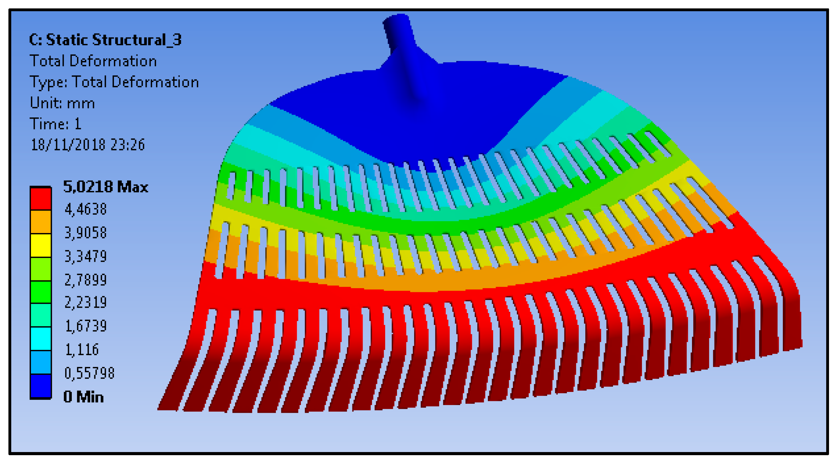
The result of the static test was 5.0197 mm of maximum deformation, which was concentrated in the final area of the teeth of the rake (Figure 12). As is shown in Figure 13, the areas with greater tension were located at the start of the final sections of the central teeth and the adjacent area where the handle is embedded in the main body of the rake, which needed to be strengthened by adding more material. The following values were obtained: 3.71 × 10⁻⁷ MPa (minimum equivalent stress) and 155.81 MPa (maximum equivalent stress).

3.1. Design Optimisation

In a first attempt to improve and optimise the design, the aim was to reduce the volume of the product, thus minimising the tensions in the dangerous points. To this end, the following parameters were modified (Table 4), located as they are in Figure 14.
The distribution of tensions was determined again using the ANSYS software, obtaining lower von Mises tensions, from 155.81 MPa to 144.47 MPa, which is a 7.28% decrease (Figure 15). This von Mises stress reduction are higher than the one achieved by Yang et al. [34], which was 2.40%. Conversely, authors such as Ghosh et al. [19] have succeeded in reducing the stress significantly by 27.22% in a guided robotic arm, after adding a support in the link which can cause failure. Yao et al. [16], by modifying angular parameters, reached 36.4% von Mises stress reduction. Yu et al. [35] achieved 31.89% von Mises stress reduction by reducing the weight of the structure. As is shown in Figure 18, the object was more relaxed regarding the distribution of tensions. Thus, after these results, it was observed that, in order to reduce the generated tensions, the upper ends of the body of the rake must be at 45°, as was previously indicated based on the strut-and-tie diagram.
However, the modification of such design parameters did not influence the deformation results of the test, obtaining a maximum total deformation of 5.0222 mm (Figure 16). Next, to continue with the optimisation of the design, the width of the lower spikes was modified, which is a parameter related to the teeth (test 3). This parameter (W_Nerve_2) was increased from 27 to 40 mm to gather the tensions of the embedment of the teeth (Table 5). That is, the start of the teeth was modified, changing from a plane to an arch. This modification was performed at the end of the optimisation. The other parameters were not modified since they were considered to be of little or no relevance in the optimisation.
Figure 17 shows that the maximum von Mises tensions increased to 212.15 MPa, which is a 46.84% increase from the value obtained in test 2 (144.47 MPa) and 36.16% with respect to the first test. Therefore, it is deduced that the increase in nerve width 2 was not relevant for the optimisation. However, the minimum von Mises tensions decreased 6.94% with respect to the improvement achieved in test 2. Similarly, Arcar et al. [36], in one of their optimisation tests for an automobile torque arm, managed to maintain the maximum tension while decreasing the minimum tensions by 53.88%, although the optimal achievement in design optimisation is to decrease both the maximum and minimum tensions [37,38].
The total deformations did not show significant differences with respect to the values obtained with the first modification, after altering the following parameters: r 1 Handle, R L1-L2 and R L2-L3 (Figure 18). Next, in test 4, the parameters related to the final section of the teeth were modified, i.e., the length (shortening) and radius (increase) of the teeth (Table 6, Figure 19).
In the third modification (test 4), the maximum tension decreased again, down to 144.87 MPa (Figure 20), although that is still slightly higher than the result obtained in test 2. The maximum von Mises tensions decreased by 7.02% and the minimum tensions decreased by 74.64% with respect to the first test (initial level). However, in test 4, the obtained results are less promising than the ones obtained in test 2, in which the values of both tensions (maximum and minimum) were optimal.
Maximum tension values of 64 MPa were obtained in the teeth. Regarding the total deformations, it was in test 4 where tooth length was reduced and tooth radius was increased, obtaining the lowest maximum deformations, i.e., 5.0004 mm, which is 0.38% lower than the value obtained in the initial test, and 0.43% lower with respect to test 2 (Figure 21).
Another improvement of the design of the rake, achieved in test 5, resulted from strengthening the lower embedment area of the handle where the tensions accumulate, designing it with excess thickness. Using ANSYS, a “Face Sizing” was applied to the strengthened area, in order to facilitate the capture of the points (Figure 22).
In test 5, there were significant decreases in maximum von Mises tension (140.13 MPa), around 3.00% with respect to the value obtained in test 2, which makes it the optimal design. Moreover, there was a 47.58% decrease in the minimum tensions with respect to test 2 (Figure 23). The tension accumulation areas that were strengthened showed lower tension values, between 62 and 77 MPa. By strengthening the lower embedment area of the handle, it was possible to reduce the maximum von Mises tension by 10.06% with respect to the initial test. However, regarding the values of total deformations obtained in test 5, where the lower embedment area of the handle was strengthened, there were no substantial improvements. The maximum deformation was reduced by 0.0206 mm with respect to test 2 (Figure 24), and 0.0181 mm with respect to the initial situation. The total deformation decreased by 0.36% with respect to the initial test.
3.2. Possible Future Improvements

Another improvement worth studying consists in reducing the volume of the material required to manufacture the object. To this end, it is proposed to reduce the general thickness of the plastic (polypropylene) to 1.8 mm. In this improvement simulation, it is also proposed to reduce the final tooth radius to 1.5 mm (Table 7).

4. Conclusions

The most widely used rake in olive harvesting is plastic-injection model. In this study, it was possible to parameterise such a rake using the CATIA software. The parameters that must be established for its optimisation are the following:
-
Sweep distance: the distance between the ends. This usually ranges between 50 and 70 cm;
-
A compression direction of 45° from the handle to the teeth, creating two lines at 45° from the two ends toward the embedment area of the handle.
Regarding the optimisation, once the main scheme was designed, interesting results were obtained by strengthening the lower embedment area of the handle, with excess thickness or stiffeners, where the tensions accumulate. The von Mises tensions were reduced by 10.06%, and the total deformation by 0.36%. The increase of the radius of the contour of the handle where it anchors to the body of the rake, as well as the radius between the first and second sides and between the second and third sides, reduced the maximum tensions by 7.28%. Once the part where the greatest tensions accumulate is strengthened, it suffices to shape the teeth (curved or straight) depending on the product to be swept, to fix the final distance between teeth. Lastly, it is also convenient to design the corresponding union arches.
By considering the internal functioning of the rake, according to the strut-and-tie model, the possible improvements regarding the design must be explored based on such knowledge related to the behaviour of the strain of the rake fibres. Firstly, the areas at risk of failure, that is, the tractionated areas, must be strengthened with greater thickness (in this study, this was the area of the final teeth where they are anchored to the body of the rake). Secondly, the posterior part of the teeth must be strengthened in the area where they are bound to the traction strengthening strap.

Author Contributions

Conceptualisation, F.J.G.-S. and R.E.H.F.; methodology, F.J.G.-S., R.E.H.F. and P.T.-T.; validation, F.J.G.-S. and R.E.H.F.; investigation, F.J.G.-S., R.E.H.F. and P.T.-T.; resources, F.J.G.-S.; data curation, F.J.G.-S., P.C.-C. and P.T.-T.; writing—original draft preparation, F.J.G.-S., P.T.-T. and P.C.-C.; writing—review and editing, R.E.H.F., P.C.-C. and P.T.-T.; supervision, P.T.-T. and P.C.-C. All authors have read and agreed to the published version of the manuscript.

Funding

This research received no external funding.

Conflicts of Interest

The authors declare no conflict of interest.

References

  1. Niavis, S.; Tamvakis, N.; Manos, B.; Vlontzos, G. Assessing and Explaining the Efficiency of Extensive Olive Oil Farmers: The Case of Pelion Peninsula in Greece. Agriculture 2018, 8, 25. [Google Scholar] [CrossRef] [Green Version]
  2. MAPAMA. Encuesta Sobre Superficies Y Rendimientos de Cultivos. Ministerio de Agricultura, Pesca y Alimentación. 2019. Available online: https://www.mapa.gob.es/es/estadistica/temas/estadisticas-agrarias/boletin2019_tcm30-536911.pdf (accessed on 20 June 2020).
  3. Triviño-Tarradas, P.; Carranza-Cañadas, P.; Mesas-Carrascosa, F.J.; Gonzalez-Sanchez, E.J. Evaluation of Agricultural Sustainability on a Mixed Vineyard and Olive-Grove Farm in Southern Spain through the INSPIA Model. Sustainability 2020, 12, 1090. [Google Scholar] [CrossRef] [Green Version]
  4. Tempesta, T.; Vecchiato, D. Analysis of the Factors that Influence Olive Oil Demand in the Veneto Region (Italy). Agriculture 2019, 9, 154. [Google Scholar] [CrossRef] [Green Version]
  5. Zambon, I.; Serra, P.; Salvia, R.; Salvati, L. Fallow Land, Recession and Socio-Demographic Local Contexts: Recent Dynamics in a Mediterranean Urban Fringe. Agriculture 2018, 8, 159. [Google Scholar] [CrossRef] [Green Version]
  6. Consejería de Agricultura. El Olivar Andaluz. Unidad de Prospectiva. 2002. Available online: http://www.juntadeandalucia.es/agriculturaypesca/prospectiva/Olivar4_doc_sinAnexo.pdf (accessed on 24 June 2020).
  7. Anta-Félez, J.L.; Peinado-Rodríguez, M. Women in Andalusian olive grove. New and old forms in agricultural work. Methaodos Rev. Ciencias Soc. 2019, 7, 302–313. [Google Scholar] [CrossRef]
  8. Romero, P.; García, J.; Botía, P. Cost-benefit analysis of a regulated deficit-irrigated almond orchard under subsurface drip irrigation conditions in Southeastern Spain. Irrig. Sci. 2006, 24, 175–184. [Google Scholar] [CrossRef]
  9. Birger, R.; Abd-ElHadi, F.; Ronen, A.; Cohen, E.; Ankorion, Y.; Najjar, A.; Moreno, J. Olive HarvesVant, a new harvest-aid formulation for improving fruit abscission and mechanical harvesting. In Proceedings of the Fifth International Symposium on Olive Growing, Izmir, Turkiye, 27 September–2 October 2004; Ozkaya, M.T., Lavee, S., Ferguson, L., Eds.; 2004. [Google Scholar] [CrossRef]
  10. Morales-Sillero, A.; Rallo, P.; Jimenez, M.R.; Casanova, L.; Suarez, M.P. Suitability of Two Table Olive Cultivars (′Manzanilla de Sevilla′ and ′Manzanilla Cacerena′) for Mechanical Harvesting in Superhigh-density Hedgerows. Hortscience 2014, 49, 1028–1033. [Google Scholar] [CrossRef]
  11. Famiani, F.; Farinelli, D.; Urbani, S.; Al Hariti, R.; Paoletti, A.; Rosati, A.; Esposto, S.; Selvaggini, R.; Taticchi, A.; Servili, M. Harvesting system and fruit storage affect basic quality parameters and phenolic and volatile compounds of oils from intensive and super-intensive olive orchards. Sci. Hortic. 2020, 263, 109045. [Google Scholar] [CrossRef]
  12. Metodo De Bielas Y Tirantes. Available online: https://issuu.com/mers/docs/monografia_m6_metodo_de_bielas_y_tirantes (accessed on 26 August 2020).
  13. Verma, R.; Singh, S.; Dalai, M.K.; Saravanan, M.; Agrawal, V.V.; Srivastava, A.K. Photocatalytic degradation of polypropylene film using TiO2-based nanomaterials under solar irradiation. Mater. Des. 2017, 133, 10–18. [Google Scholar] [CrossRef]
  14. Loizaga, A.; Serturcha, J.; Suárez, R. Defectos metalúrgicos generados por la presencia de gases en el metal fundido. An. Quim 2008, 104, 111–119. [Google Scholar]
  15. Patel, D.K.; Kalidindi, S.R. Correlation of spherical nanoindentation stress-strain curves to simple compression stress-strain curves for elastic-plastic isotropic materials using finite element models. Acta Mater. 2016, 112, 295–302. [Google Scholar] [CrossRef] [Green Version]
  16. Yao, K.T.; Chen, C.S.; Cheng, C.K.; Fang, H.W.; Huang, C.H.; Kao, H.C.; Hsu, M.L. Optimization of the Conical Angel Design in Conical Implant-Abutment Connections: A Pilot Study Based on the Finite Element Method. J. Oral Implantol. 2018, 44, 26–35. [Google Scholar] [CrossRef] [PubMed]
  17. Hedia, H.S.; Barton, D.C.; Fisher, J.; Elmidany, T.T. A method for shape optimization of a hip prothesis to maximize the fatigue life of the cement. Med. Eng. Phys 1996, 18, 647–654. [Google Scholar] [CrossRef]
  18. Ingeniería y Construcción. 2020. Available online: https://civilgeeks.com/2011/10/23/la-plastificacion-de-la-seccion-transversal-de-una-viga-respuesta-a-la-pregunta-de-estructuras-metalicas/ (accessed on 25 May 2020).
  19. Ghosh, T.; Roy, A.; Mishra, R.; Kamlesh, S.S. Structural optimization of a CT guided robotic arm based on static analysis. Mater. Proc. 2018, 5, 19586–19593. [Google Scholar] [CrossRef]
  20. Wang, X.; Li, B.; Yang, Z. Finite Element Analysis and Lightweight Optimization Design on main Frame Structure of Large Electrostatic Precipitator. Adv. Mater. Sci. Eng. 2018, 9, 1–11. [Google Scholar] [CrossRef] [PubMed] [Green Version]
  21. Rojas-Sola, J.I.; De la Morena-De la Fuente, E. The conical stones olive oil mill: Analysis through computer-aided engineering. Agriculture 2020, 7, 255. [Google Scholar] [CrossRef]
  22. Rojas-Sola, J.I.; De la Morena-De la Fuente, E. Agustin de Betancourt′s plunger lock: Analysis of its construction through computer-aided engineering. Inf. Constr. 2019, 71, e286. [Google Scholar] [CrossRef]
  23. Rojas-Sola, J.I.; De la Morena-De la Fuente, E. Agustin de Betancourt′s double-acting steam engine: Analysis through computer-aided engineering. Appl. Sci. 2018, 8, 2309. [Google Scholar] [CrossRef] [Green Version]
  24. Rojas-Sola, J.I.; De la Morena-De la Fuente, E. Agustin de Betancourt′s mechanical dredger in the port of Kronstadt: Analysis through computer-aided engineering. Appl. Sci. 2018, 8, 1338. [Google Scholar] [CrossRef] [Green Version]
  25. Rojas-Sola, J.I.; De la Morena-De la Fuente, E. Agustin de Betancourt’s wind machine for draining marshy ground: Analysis of its construction through computer-aided engineering. Inf. Constr. 2018, 70, e236. [Google Scholar] [CrossRef]
  26. Rojas-Sola, J.I.; De la Morena-De la Fuente, E. Agustin de Betancourt’s mill for grinding flint: Analysis by computer-aided engineering. Dyna 2018, 93, 165–169. [Google Scholar]
  27. Javidinejad, A. Theory in parametric design optimization approach via finite element analysis. Adv. Theor. Appl. Mech. 2012, 5, 217–224. [Google Scholar]
  28. Ramesh, B.T.; Koppad, V.; Raju, H. Analysis Optimization of Connecting Rod With Different Materials. World J. Res. Rev. 2017, 4, 33–39. [Google Scholar]
  29. Ozkurt-kayahan, Z.; Turgut, B.; Akin, H.; Kayahan, M.B.; Kazazoglu, E. A 3D finite element analysis of stress distribution on different thicknesses of mineral trioxide aggregate applied on various sizes of pulp perforation. Clin. Oral. Investig. 2020, 1–7. [Google Scholar] [CrossRef]
  30. Rojas-Sola, J.I.; De la Morena-De la Fuente, E. The Hay inclined plane in Coalbrookdale (Shropshire, England): Analysis through computer-aided engineering. Appl. Sci. 2019, 9, 3385. [Google Scholar] [CrossRef] [Green Version]
  31. Punarselvam, E.; Sikkandar, M.Y.; Bakouri, M.; Parakash, N.B.; Jayasankar, T.; Sudhakar, S.J. Different loading condition and angle measurement of human lumbar spine MRI image using ANSYS. J. Ambient Intell. Hum. Comput. 2020, 14. [Google Scholar] [CrossRef]
  32. Budynas, R.G.; Nisbett, J.K. Shigley′s Mechanical Engineering Design, 9th ed.; McGraw-Hill Publisher: New York, NY, USA, 2011. [Google Scholar]
  33. Jahanbakhshi, A.; Heidarbeigi, K. Simulation and Mechanical Stress Analysis of the Lower Link Arm of a Tractor Using Finite Element Method. J. Fail. Anal. Prev. 2019, 19, 1666–1672. [Google Scholar] [CrossRef]
  34. Yang, Y.; Zeng, Q.; Wan, L.; Wang, C.; Gao, K. Optimization of Slider-Type Hydraulic Powered Support (SHPS) using FEA and Response Surface Methodology. Tech. Gazette 2020, 27, 497–505. [Google Scholar]
  35. Yu, X.; Pang, X.; Zou, Z.; Zhang, G.; Hu, Y.; Dong, J.; Song, H. Lightweight and High-Strength of an Excavator Bucket under Uncertain Loading. Math. Probl. Eng. 2019, 1, 1–12. [Google Scholar] [CrossRef]
  36. Arcar, E.; Tútem, N.; Güler, M.A. Design optimization of an automobile torque arm using global and successive surrogate modeling approaches. J. Automob. Eng. 2018, 233, 1453–1465. [Google Scholar] [CrossRef]
  37. Chethan, K.N.; Mohammad, Z.; Shyamasunder, B.N.; Sattish, S.B. Static structural analysis of different stem designs used in total hip arthroplasty using finite element method. Heliyon 2020, 6, e01767. [Google Scholar]
  38. Sathish, T.; Dinesh Kumar, S.; Karthick, S. Modelling and analysis of different connecting rod material through finite element route. Mater. Today Proc. 2020, 21, 971–975. [Google Scholar] [CrossRef]
Figure 1. Types of rakes in the market: (a) rectangular (b) triangular.
Agriculture 10 00379 g001
Figure 2. Stress diagram in rake operation.
Agriculture 10 00379 g002
Figure 3. Strain scheme.
Agriculture 10 00379 g003
Figure 4. CATIA (computer-aided three dimensional interactive application) representation of the area of the teeth/spikes of the rake.
Agriculture 10 00379 g004
Figure 5. Representation of the posterior part of the rake.
Agriculture 10 00379 g005
Figure 6. Description of the parameters of the hand-rake sweeper. Views: left view (a), front view (b), isometric view (c) and top view (d).
Agriculture 10 00379 g006
Figure 7. Strain scheme of the rake in action.
Agriculture 10 00379 g007
Figure 8. Strain scheme of the rake.
Agriculture 10 00379 g008
Figure 9. Flexion-traction scheme in a beam [18].
Agriculture 10 00379 g009
Figure 10. Nonstructured triangular mesh created with ANSYS software.
Agriculture 10 00379 g010
Figure 11. ANSYS factor of safety.
Agriculture 10 00379 g011
Figure 12. Total deformations obtained with ANSYS—initial situation (test 1).
Agriculture 10 00379 g012
Figure 13. ANSYS von Mises tensions of the rake—initial level (test 1).
Agriculture 10 00379 g013
Figure 14. Modified design parameters (r_1_ Handle; R_L1_L2; R_L2_L3), (test 2).
Agriculture 10 00379 g014
Figure 15. ANSYS von Mises tensions with modified design parameters (test 2).
Agriculture 10 00379 g015
Figure 16. ANSYS total deformations (test 2).
Agriculture 10 00379 g016
Figure 17. ANSYS von Mises tensions (test 3).
Agriculture 10 00379 g017
Figure 18. ANSYS total deformations (test 3).
Agriculture 10 00379 g018
Figure 19. Modified design parameters (R_Up_Teeth, L_Teeth) (test 4).
Agriculture 10 00379 g019
Figure 20. ANSYS von Mises tensions (test 4).
Agriculture 10 00379 g020
Figure 21. ANSYS total deformations (test 4).
Agriculture 10 00379 g021
Figure 22. Triangulation of the strengthening using the ANSYS software (concentration of tension in the handle).
Agriculture 10 00379 g022
Figure 23. ANSYS von Mises tensions (test 5).
Agriculture 10 00379 g023
Figure 24. ANSYS total deformations (test 5).
Agriculture 10 00379 g024
Table 1. Colorimetric classification of the parameters for the design of a hand-rake sweeper.
FIXED PARAMETERS: fundamentally, they depend on the type of fruit to be swept. They are set at the beginning of the design and are not modified. For example, “total rake width”, that is, the length to be swept per sweep.
MODIFIABLE PARAMETERS WITH NO REPERCUSSION IN THE STRUCTURAL OPTIMISATION OF THE MODEL: these parameters do not influence the optimisation of the design. For example, “tooth radius” and “draft angle”.
STUDY PARAMETERS: these must be modified to influence the optimisation of the design.
Table 2. Design parameters and their initial values.
VariableDescriptionTypeInitial Value Units
ThicknessThickness 2.5mm
Stick DiameterHandle diameter 25mm
L_H_1Horizontal L of the first side 82mm
Angle_L2Angle of the second side 15°
a_0Vertical L between the start of the handle and the start of the body 60mm
L_H_2Horizontal L of the second side 150mm
a3_L up to the end of the body 755mm
A_L3Angle of the third side 65.0°
r_1_HandleRadius of the contour of the handle where it is anchored with the body 20.0mm
R_L1-L2Radius between the first and second sides 12.0mm
R_L2_L3Radius between the second and third sides 7.5mm
d_1_PlaneReference plane to make the teeth 70.0mm
s_1_plasticHorizontal distance of each tooth in the reference plane (d_1_Plane) 12.0mm
S2_holeHorizontal distance of each space between teeth in the reference plane (d_1_Plane) 7.0mm
d2_level_PlaneStart of the teeth 80.0mm
R_Arc_LowerRadius of the lower arch where the teeth end 2560.0mm
Dis_Arc_LowerDistance over the symmetry axis from the handle to the end of the teeth 330.0mm
R_Nerve_1Radius of the upper tooth 1120.0mm
W_Nerve_1Width of the upper tooth 32.0mm
D_Nerve_1Distance over the symmetry axis from the handle to the axis of tooth 1 200.0mm
D_Nerve_2Distance over the symmetry axis from the handle to the axis of tooth 2 260.0mm
R_Nerve_2Radius of the lower tooth 2780.0mm
W_Nerve_2Width of the lower tooth 27.0mm
L_TeethLength of the teeth 87.9mm
Up_Thickness_TeethExcess thickness of the teeth 0.0mm
R_TeethRadius of the teeth 35.0mm
R_Up_TeethIncrease of the radius of the teeth 0.0mm
R_GeneralGeneral radius 1.0mm
R_2_HandleRadius of the corner between the handle and the body 23.0mm
R_General_CornerGeneral radius of the corners between teeth 3.0mm
R_End_TeethRadius of the end of the teeth 2.0mm
R_Var_HandleVariable radius of the corner between the handle and the body 3.mm
L_HandleHandle length 100.0mm
L_Screw_HandleDistance from the holding point of the handle to the body of the rake 27.0mm
D_Screw_HandleDiameter of the handle screw 1.5mm
Teeth_DraftingDrafting of the teeth 25.0°
Handle_DraftingDrafting of the inside of the handle 3.0°
General_DraftingGeneral drafting 1.5°
Table 3. Design parameters of the rake. Modified values.
ParameterNo. TestsDescriptionTypeInitial Value (mm)Modified Value (mm)
Thickness6Thickness 2.51.8
r_1_Handle2Radius of the contour of the handle where it is anchored to the body 20.040.0
R_L1-L22Radius between the first and second sides 12.020.0
R_L2_L32Radius between the second and third sides 7.520.0
W_Nerve_23Width of the bottom spike 27.040.0
L_Teeth4Tooth length 87.930.0
R_Up_Teeth4Increase of tooth radius 0.03.0
R_End_Teeth6Final tooth radius 2.01.5
Table 4. Rake design modified parameters (test 2).
ParameterInitial Value (mm)Modified Value (mm)
r_1_Handle20.040.0
R_L1-L212.020.0
R_L2_L37.520.0
Table 5. Modified rake design parameter (test 3).
ParameterInitial Value (mm)Modified Value (mm)
W_Nerve_227.040.0
Table 6. Modified rake design parameters (test 4).
ParameterInitial Value (mm)Modified Value (mm)
L_Teeth87.930.0
R_Up_Teeth0.03.0
Table 7. Rake design parameters to modify in future research lines for its optimisation.
ParameterInitial Value (mm)Modified Value (mm)
Thickness2.51.8
R_End_Teeth2.01.5