Article

Design Matching and Dynamic Performance Test for an HST-Based Drive System of a Hillside Crawler Tractor

1
College of Mechanical and Electronic Engineering, Northwest A&F University, Yangling 712100, China
2
Scientific Observing and Experimental Station of Agricultural Equipment for Northern China, Ministry of Agriculture and Rural Affairs, Yangling 712100, China
3
Ministry of Agriculture and Rural Affairs Apple Full Mechanization Research Base, Yangling 712100, China
4
State Key Laboratory of Soil Erosion and Dryland Agriculture on Loess Plateau, Yangling 712100, China
*
Author to whom correspondence should be addressed.
Agriculture 2021, 11(5), 466; https://doi.org/10.3390/agriculture11050466
Submission received: 6 April 2021 / Revised: 13 May 2021 / Accepted: 17 May 2021 / Published: 20 May 2021
(This article belongs to the Section Agricultural Technology)

Abstract

:
In recent years, research into and development of hillside tractors has become a popular topic in the field of agricultural engineering in China. To solve the main problems associated with a low adjustment range of the working speed, complex operation, and low safety for slope operation of medium-sized crawler tractors, a hydrostatic drive system that can be used for hillside crawler tractors was designed. According to the operation requirements of a hillside crawler tractor, the parameters of the three-cylinder diesel engine, hydrostatic transmission (HST), drive rear axle, and other key components of the drive system were matched after the force and motion analyses of the tractor, and then the main performance indicators, including the traction performance, system pressure and working speed of the drive system were verified. On this basis, a drive system performance test bench was built, and the traction performance and starting acceleration performance of the drive system was tested. The results of the traction bench test show that when the engine was at the maximum torque point of 1700 r/min, the maximum theoretical tractive force outputted by the tractor in Gear I was 114,563 N, and the maximum theoretical tractive force outputted by tractor in Gear II was 10,959.2 N, which were both larger than the traction resistance of 9550.6 N experienced by the hillside tractor ploughing on the slope. The results of the initial acceleration bench test show that the tractor driving speed can gradually increase with increasing output of the variable pump and can reach the maximum in 3 s. When the tractor was driving on flat ground, the maximum driving speeds of Gear I, Gear II, and Gear III were 4.65 km/h, 6.58 km/h, and 8.57 km/h, respectively, which are close to the theoretical values. When the tractor was driving on a 15° slope, the maximum driving speeds of Gear I, Gear II, and Gear III were 4.55 km/h, 6.25 km/h, and 8.28 km/h, respectively. It can be concluded that the design matching of the drive system is reasonable, the speed consistency is good and there is enough power reserve, which can meet the requirements for a large workload.

1. Introduction

The hilly and mountainous areas in China account for approximately 69.4% of the total national territorial area [1]. At present, the amount of agricultural equipment in the plain areas of China is relatively high and developing rapidly, while the progress of agricultural mechanization in hilly areas is less developed. The development of agricultural mechanization in hilly and mountainous areas is restricted for two reasons. The first is that the farmland area in hilly and mountainous areas is small, the shape is irregular, and the slope is steep, and the second is that research into and development of hillside tractors in China is still in its early stages, and the supply of hillside tractors that can meet the operation requirements in hilly areas is insufficient. Therefore, there is an urgent need to develop tractors that can operate in the hilly and mountainous areas of China [2,3,4].
A crawler tractor has the advantages of good traction performance, lower ground pressure, and excellent climbing ability, and is especially suitable for farmland operation in hilly and mountainous areas [5,6]. In China, small and medium sized crawler tractors mostly use traditional mechanical gearboxes. This kind of gearbox has many gears. The operator needs to shift gears frequently during operation, and there is power interruption when shifting. When the tractor is working on a slope, it can slip easily if it is not operated properly, thus reducing the safety factor. The advantages of the hydrostatic drive include a high power to mass ratio, low failure rate, convenient maintenance, overload protection, and bidirectional drive [7,8,9,10]. The use of a hydrostatic drive is the preferred technical solution for tractors with medium and small horsepower and continuously variable transmission [11,12,13]. In particular, the combination of hydrostatic drives with modern electronic technology, computer control technology, and sensor technology can facilitate automatic control, which will allow the separation of man-machines, unmanned operation and, in general, the protection of operators [14,15,16]. This is in line with the future development direction of intelligent agricultural machinery [17,18].
In recent years, Kubota, Zoomlion, China YTO, and other well-known agricultural machinery enterprises have developed many grain harvesters with hydrostatic drives [19,20]. Current hydrostatic drive applications are mostly found in harvesting machinery and horticultural tractors, while research in this area has been less focused on hillside tractors [21,22,23]. Based on the unique working conditions of hilly tractors, including the high weight of mobility, trafficability and safety, hydrostatic technology has become the main technical breakthrough point for this type of tractor [24]. In light of this, this paper develops a drive system for hillside crawler tractors based on a hydrostatic transmission (HST) and presents the results of tests and analyses of its dynamic performance. Therefore, this paper provides a theoretical basis and technical support for further research on and development of hillside crawler tractors.

2. Materials and Methods

2.1. Main Performance and Technical Parameters of the Drive System

Hillside crawler tractors need to meet various working conditions, such as transport, ploughing, fertilization, and seeding. At present, China do not have standards for the design of the hillside tractor; the development of the parameters is mainly based on the design experience of the crawler tractors and the characteristics of agricultural mechanization production in hilly mountainous areas of China [25,26,27].
The theoretical working speeds of agricultural crawler tractors are shown in Table 1.
The main characteristics of the Chinese agricultural mechanization production are as follows: (1) the farmland area is small and scattered, which is suitable for the operation of small and medium sized agricultural machinery; and (2) the gradient of the slope which is suitable for mechanized farming and planting is no more than 15°. On this basis, the main technical parameters of the hillside crawler tractor are shown in Table 2.

2.2. Structure of the Drive System

In relation to the different speed adjustment methods, the hydrostatic transmission drive system can be divided into variable pump-quantitative motors, quantitative pump-variable motors, variable pump-variable motors, etc. Adjustments can be made according to whether the driving wheel is directly driven by the hydraulic motor. The hydrostatic drive system can be divided into a low-speed scheme and a high-speed scheme [28]. To reduce the manufacturing cost and facilitate the application of this tractor in rural mountainous areas with limited economic resources, a hydrostatic transmission system by using variable pump-quantitative motor and high-speed scheme with the advantage of simple structure, low cost, and good versatility was applied in this paper. The drive system of the hillside crawler tractor is mainly composed of an engine, a clutch, a HST, and a driving rear axle. The sketch of the structure of the drive system is shown in Figure 1.
Through the clutch and the acceleration of the transfer case, the power of the engine drives the piston variable pump to run, and then drives the bidirectional hydraulic motor to run. The rear part of the bidirectional hydraulic motor is connected to the driving rear axle, which transmits the power to the driving wheel after reducing the speed and increasing the torque. The swash plate adjusting mechanism is used to adjust the displacement and flow direction of the piston variable pump, which can change the speed and rotation direction of the bidirectional hydraulic motor to adjusts the driving speed and moving direction of the tractor. In the drive system, the check valve and overflow valve constitute positive and negative high-pressure overflow systems, respectively, which are used to prevent system components damage due to high pressure. The oil pump, filter and overflow valve constitute a low-pressure oil-supplement system, which is used to compensate for the leakage of the system and prevent cavitation. The radiator is used to prevent the damage of hydraulic components caused by system temperature exceeding rated values.

2.3. Force Analysis of the Hillside Crawler Tractor

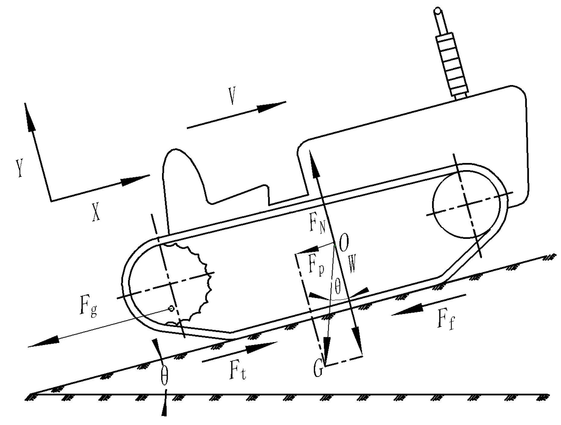
When the tractor works in the field, the driving resistance need to be overcame includes the internal resistance and external resistance of the running gear, as shown in Figure 2.
The external resistance of the crawler tractor includes the rolling resistance Ff from the ground, ramp resistance Fp when uphill, and drive resistance Fg [29]. The air resistance and the acceleration resistance is neglected due to the low speed. The driving resistance Ft which the tractor needs to be overcame when working is as follows:
F t = F i + F f + F p + F g
The internal resistance of the running gear of the tractor is mainly caused by the extrusion and friction between the track shoe and the driving wheel, the guide wheel, the towing wheel, and the supporting wheel, which is generally calculated according to the following formula:
F i = ( 0.05 ~ 0.10 ) G
where G is the gravity of the tractor (N).
When the tractor is driving, the contact between the track and the ground causes deformation of the track and the ground, resulting in normal and tangential interaction forces, which hinder the tractor from moving forward. According to the principle of moment balance, the rolling resistance is usually estimated by the following formula:
F f = f W
where f is the rolling resistance coefficient, which is in the range of 0.05–0.12 based on different ground types. W is the normal load (N).
When the tractor moves along the slope, there is a component force of gravity along the slope, that is, the slope resistance:
F P = G sin θ
where θ is the slope angle (°).
When the tractor works with agricultural implements, it will produce traction resistance, which is related to the implement type and specification, operation type, soil properties, and other factors.
When ploughing, the traction resistance of the tractor is the ploughing resistance RG. There are many factors that can affect the ploughing resistance, when the detailed parameter of the plough is unknown, the calculation formula that can be used for estimating ploughing resistance according to the design metrics is as follows:
R G = K B h
where K is the soil specific resistance (N/cm2), which ranges from 2.0–8.0 according to different soil properties; B is the working width of the plough(cm); and h is the ploughing depth of the plough share (cm).
In the process of land preparation, the traction resistance of the tractor is R, and R is the working resistance of the land preparation equipment, such as the spiked tooth harrow, the cultivator, and the planter.
R = K b
where K is the specific resistance of agriculture implements (N/m), which ranges from 550–3000 N/m according to different implementation types, and b is the working width of the soil preparation machine (m).
When the tractor works in the field, the driving wheel of the tractor needs to output torque to overcome the driving resistance, which is the drive torque, the calculation formula is:
M q = F t r d
where rd is the radius of the driving wheel (m).
The power consumed by the tractor during operation can be calculated according to the formula as follows:
P 0 = F t v o 3.6
where vo is the maximum working speed (km/h).
According to the requirements of the main parameter of the dynamic performance of the hillside crawler tractor which were shown in Table 2 above, the loads and power of the tractor in the conditions of driving, seeding, and ploughing on flat ground (0°) and slopes (15°) was calculated through Formulas (1), (7), and (8); the calculated results are shown in Table 3.

2.4. Motion Analysis of the Hillside Crawler Tractor

It is assumed that there is no loss of volumetric efficiency in the hydrostatic drive system and there is no relative slip between the tractor and the ground, the driving speed of the tractor is equal to the peripheral speed of the driving wheel. The theoretical driving speed of the tractor is:
v t = 1.2 × 10 1 π n r d i p i m
where Vt is the theoretical driving speed of the tractor (km/h); n is the engine speed, (r/min); ip is the transfer case transmission ratio; and im is the transmission ratio from the quantitative motor to the driving half shaft.
There is a certain loss of volumetric efficiency and relative slip between the tractor and the ground. According to the flow continuity equation and transmission relationship, the actual driving speed of the tractor is:
v = v t η p v η m v q p ( 1 δ ) q m = 1.2 × 10 1 π r d η p v η m v n q p ( 1 δ ) q m i m i p
where v is the actual driving speed of the tractor (km/h); ηpv is the volumetric efficiency of the variable pump; ηmv is the volumetric efficiency of the quantitative motor (%); qp is the displacement of the displacement pump (mL/r); qp is the displacement of the quantitative motor (mL/r); and δ is the slip rate of the crawler tractor (%). To ensure that the tractor can be operated in a high drive efficiency range, the slip rate of the crawler tractor is generally less than 7%.

2.5. Parameter Matching of the Key Components of the Drive System

2.5.1. Engine Matching

When the tractor is working, the engine not only needs to meet the operation requirements of the tractor (P1) but also needs to meet the requirements for the power consumed by tractor steering, farm tool lifting, and other hydraulic control systems (P2), as well as the power consumed by engine cooling, tractor lighting, and other systems (P3, assuming 1 kW) need to be met. Therefore, the rated power of the engine (Pe) should meet the following condition:
P e P 1 + P 2 + P 3
According to the Table 3, the maximum power consumption (Pmax) during operation of the tractor is 11.94 kW, the transmission efficiency(ηt) of the general hydrostatic drive system is 0.7, then the output power of engine meeting the tractor operation requirement is:
P 1 = P m a x η t = 11.94 0.7 = 17.06 kW
The power consumed by the hydraulic control system (P2) is:
P 2 = p c Q 60 η g = 10 × 24 60 × 0.93 = 4.30 kW
where Pc is the pressure of the hydraulic control system, which is generally medium and low pressure in agricultural machinery, and is 10 MPa; Q is the displacement of the gear pump with a flow of 24 L/min; and ηg is the efficiency of the gear pump and is equal to 0.93.
According to the Formula (11), the rated power of the engine should be no less than 22.36 kW. When considering the complex working conditions of hillside tractors and the increase in the working resistance caused by the change in the performance of agricultural implements, as well as the need to maintain the normal operating factor of the tractors, a power reserve of 10%–20% should be used [30]. By comparing the products of Changchai, Weichai and other companies and fully considering the cost, performance and other indicators, the Changchai ZN390b three-cylinder diesel engine (Changchai Company Limited, Changzhou, Jiangsu, China) was finally selected, and its main performance parameters are shown in Table 4.

2.5.2. Matching of the HST

For the HST matching calculation, the hydraulic motor parameters are selected first. The determination of hydraulic motor parameters mainly includes speed and displacement. In this study, the angle power method proposed by the SAUER-DANFOSS company was used to determine the hydraulic motor parameters [31]. The tractor angular power is:
P j j = M q max n q max 9549 = F q max V K max 3600
where Pjj is the angular power of the tractor (kW); Mqmax is the maximum driving torque of the tractor (N·m); nqmax is the maximum speed of the driving half shaft (r/min); Fqmax is the maximum driving resistance of the tractor (N); VKmax is the maximum driving speed of the tractor (km/h).
According to the maximum operating speed of the tractor estimated in Table 2 and the calculated maximum driving resistance in Table 3, the angular power of the tractor is 21.2 kW.
The HST type used in this paper is a single motor, the transmission efficiency from the motor to the drive rear axle is relatively fixed, and the transmission efficiency is estimated to be 0.95. Then, the angular power of the motor is:
P m j = P j j 0.95 = 21.22 0.95 = 22.34 kW
where Pmj is the angular power of the motor (kW).
The motor displacement specification is determined according to the formula:
P m j p m a x q m n m max 60 , 000
where pmax is the maximum pressure of the system (MPa) and nmmax is the theoretical maximum speed of the motor (r/min).
When setting the system pressure, the highest pressure of the system is usually determined based on the highest nominal pressure of the components to ensure the reliability and service life of the system. Based on the pressure setting experience of agricultural machinery (harvester) [32], the highest pressure in this study was set to 32 MPa, the theoretical maximum speed of the motor was 3000 r/min, and the calculated motor displacement needed to be larger than 13 mL/r. Therefore, the LY-HPVMF-28-L-02 HST (AVIC Liyuan Hydraulic Co., Ltd., Guiyang, Guizhou, China) was selected, and its main parameters are shown in Table 5.

2.5.3. Matching of the Drive Rear Axle

There are three gears in the tractor drive rear axle. Gear I is for slow driving, which is mainly used for low speed and high load operation; Gear II is for field operation, which is mainly used for medium/low speed and medium/high load field operation by a hillside crawler tractor; and Gear III is for light load operation, which is mainly used for high speed operation such as transfer among fields and transport on roads.
The speed ratio of each gear of the tractor is generally close to the geometric progression, and the common ratio is 1.2–1.5. Based on this, the maximum speed of Gear I was set to 4 km/h, the maximum speed of Gear II was set to 6 km/h, and the maximum speed of Gear III was set to 8 km/h.
The maximum driving speed of the tractor was 8 km/h, the rated speed of the engine was 2400 r/min, the driving radius was 0.103 m, the volume efficiency of the system variable pump was 0.93, the volume efficiency of the motor was 0.93, the slippage rate was 5%, the maximum input speed of the HST variable pump was 3000 r/min, the transmission ratio of the transfer case should be 0.8 in order to match between the maximum input speed and the rated speed of the engine, and according to Formula (10), the minimum transmission ratio from the hydraulic motor to the driving wheel should be 11.96. As a result, the XL-80 driving rear axle (Huzhou Shuangli Automatic Technology Equipment Co., Ltd., Huzhou, Zhejiang, China) was selected, and its main parameters are shown in Table 6.

2.6. Performance Check of the Drive System

2.6.1. Drive Force Check

When checking the drive force, the maximum drive force should be less than the ground adhesion force so that the dynamic performance of the drive system can be effectively utilized:
F K max F φ = G φ
where FKmax is the maximum driving resistance and is 9550.6 N according to Table 3; Fφ is the ground adhesion force (N); and φ is the ground adhesion coefficient, which is 1.1.
Based on the calculation, the maximum driving resistance of 9550.6 N is less than the maximum adhesion force of 14,014.0 N, so the dynamic performance of the tractor could be effectively utilized.

2.6.2. System Pressure Check

Because the selected HST motor displacement is larger than the theoretical calculation displacement, the system will need to be rechecked. To simplify the calculation, the pressure loss of the system caused by liquid resistance was ignored, and the mechanical efficiency of the system was simplified to a fixed value when checking the system pressure. Then, the inlet and outlet pressure difference of the hydraulic motor was found to be:
Δ P m = T m 2 π q m η m m
where ΔPm is the pressure difference between the inlet and outlet of the hydraulic motor (MPa); Tm is the output torque of the hydraulic motor (N·m); ηmm is the mechanical efficiency of the motor, which is 93%; and qm is the displacement of the motor and is equal to 28 mL/r.
The output torque of the driving wheel is:
M q = T m i m η m
where ηm is the transmission efficiency from the hydraulic motor to the driving wheel.
According to Table 3 and Formulas (18) and (19), when the tractor ploughs on the slope, the driving torque of the tractor should reach the maximum value of 983.7 N·m., and the rear drive axle is generally set in Gear II to meet the speed requirements of ploughing on the slope. At the same time, the pressure difference between the inlet and outlet of the motor is 15.17 MPa, which is less than the maximum HST pressure of 32 MPa. Therefore, the hillside crawler tractor can meet the requirements of continuous heavy load operation when ploughing on sloped.

2.6.3. Driving Speed Check

Due to the difference between the actual ratio of the driving rear axle speed and the theoretical calculation value, it was necessary to recheck the driving speed of the hillside crawler tractor after the driving rear axle parameter was selected. The radius of the driving wheel was 0.103 m, the volume efficiency of the variable pump of the HST was 0.93, the volume efficiency of the hydraulic motor of the HST was 0.93, and the slippage rate of the tractor was 5%. Then, based on the parameters of the driving rear axle (Table 6) and Formula (10), the driving speed of each Gear was calculated when the engine is at a rated speed of 2400 r/min (see Table 7).
Table 7 shows that the driving speed of each gear is close to the theoretical setting value, which indicates that the drive system can meet the driving speed requirement when the tractor is working in the farming area.

2.7. Building the Drive System Test Bench

General Scheme of the Drive System Test Bench

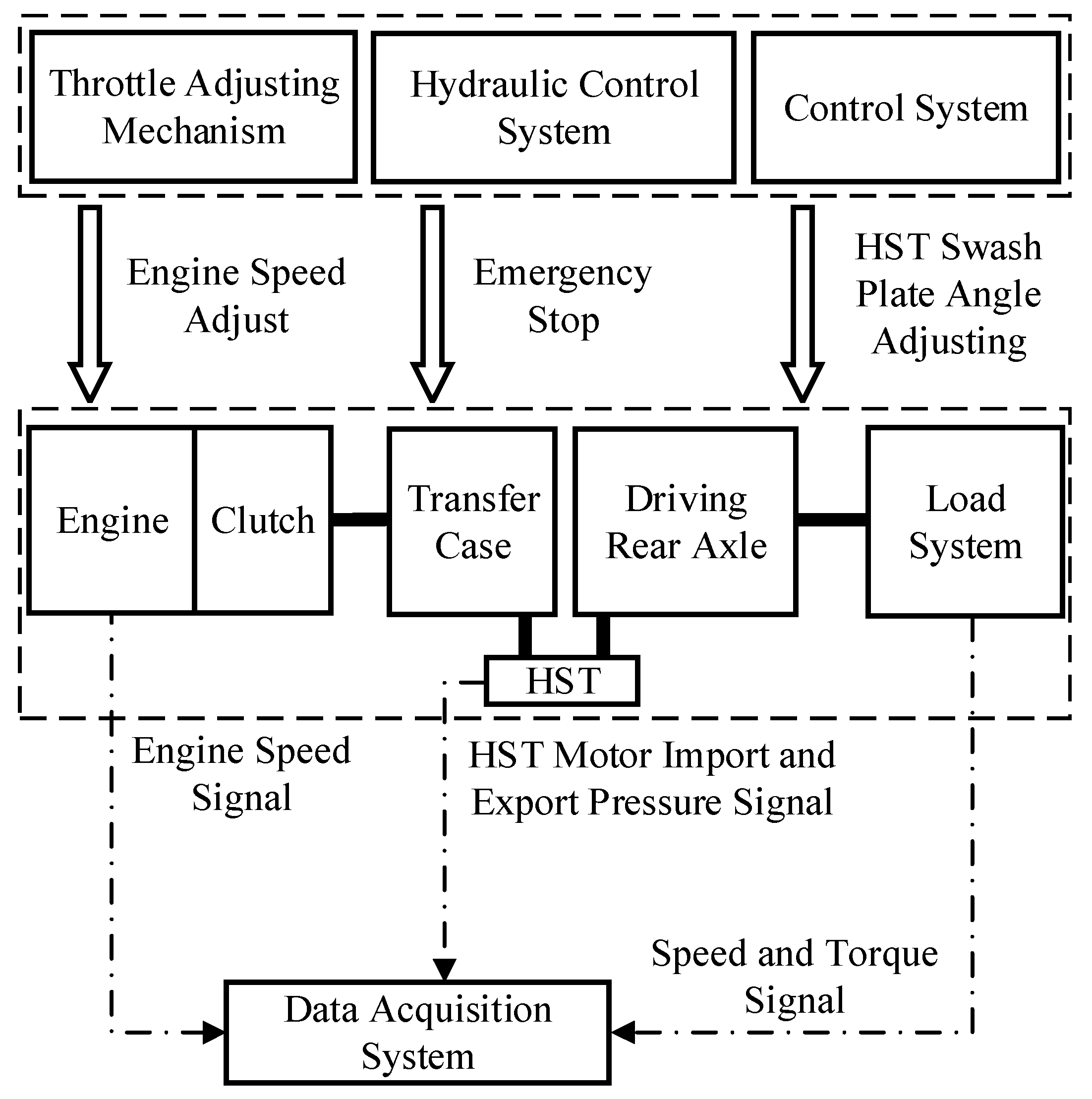
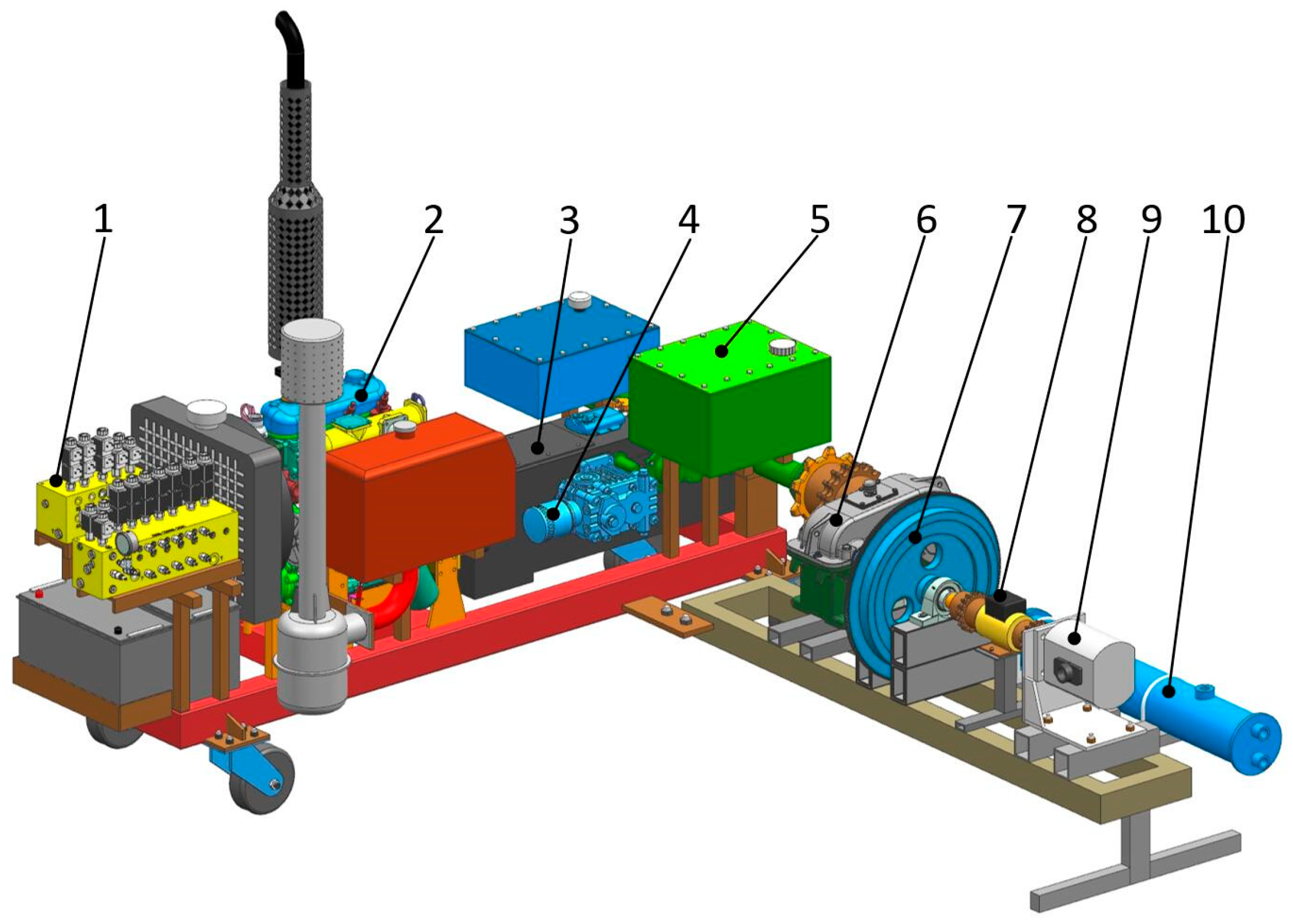
The drive system test bench of the hillside crawler tractor consisted of a mechanical unit and a test and control unit. The mechanical unit consisted of a tractor drive system, load system, throttle adjusting mechanism, hydraulic control system, etc.; the test and control unit consisted of a data acquisition system and a control system. The structural composition of the drive system test bench is shown in Figure 3, the three-dimensional model is shown in Figure 4, and the physical figure is shown in Figure 5.
As shown in Figure 3, in the drive system test bench, the load system was connected to the driving wheel of the driving rear axle to apply torque to the drive system to simulate the working load of the tractor. The operator adjusted the engine speed by operating the throttle actuator. A hydraulic control system was used for emergency braking of the drive system test bench. The CoCo-90 dynamic data analyzer (Crystal Instruments Inc., Silicon Valley, CA, USA) was used for the data acquisition system. The control system consisted of the Arduino UNO single chip microcomputer (Arduino SA Inc, Ivera, Turin, Italy), HBS657 digital stepping closed-loop driver (Hongbaoda Electric Machine Co., Ltd., Shantou, Guangdong, China). and the step motor 57HB250-112BJ (Hongbaoda Electric Machine Co., Ltd., Shantou, Guangdong, China). The step motor was connected to the HST swash plate angle adjusting shaft through an NMRV30 worm reducer (Dongguan Yutian Electric Machine Co., Ltd., Dongguan, Guangdong, China) to control the displacement and the flow direction of the variable pump.
The load system consisted of a gear increaser, a flywheel, a speed torque sensor, a hydraulic pump, an electromagnetic overflow valve, a cooler, and an oil tank. The load system was connected to the driving wheel of the driving rear axle. The gear increaser was used to increase the speed to improve the loading performance of the hydraulic pump. Gear increaser I was mainly used for low speed and high load condition tests, and gear increaser II was mainly used for high speed and low load condition tests. The installation size of gear increaser I and the gear increaser II are consistent, and they could be swapped according to the actual test requirements. The output end of the gear increaser was connected to the flywheel to simulate the actual inertia of the tractor. A speed and torque sensor was connected to the flywheel and the hydraulic pump to obtain the speed and torque information. The oil outlet of the hydraulic pump was connected to the oil inlet of the electromagnetic overflow valve, the oil outlet of the electromagnetic overflow valve was connected to the cooler, and the cooler was connected to the oil tank. The hydraulic oil from the cooler was cooled by cold water to balance the heat of the load system and avoid damage to the components of the hydraulic load system due to the high oil temperature of the load system. The structural layout of the load system is shown in Figure 6, and the type and parameters of the main components are shown in Table 8.
In the loading process, the driving wheel drove the hydraulic pump to rotate at a high speed through the gear increaser, and then the overflow oil pressure of the electromagnetic overflow valve was adjusted to control the load torque.
According to the transmission relationship, the relationship between the speed of hydraulic pump and the speed of the driving wheel is as follows:
n o = i i n q
where no is the speed of the hydraulic pump (r/min); ii is the transmission ratio of the gear increaser; and nq is the speed of the driving wheel (r/min).
Based on the principle of torque balance, the relationship between the load torque of the load system and output torque of the drive system is as follows:
T o = M q η i / i i
where To is the load torque (N·m) and ηi is the transmission efficiency of the gear increaser, which is equal to 0.98.

2.8. Dynamic Performance Test of the Drive System

2.8.1. Traction Performance Test

The traction performance is an important index for measuring the dynamic performance of the drive system of the tractor [33]. To test the limit tractive performance of the hillside crawler tractor, the engine speed was adjusted to the maximum torque of 1700 r/min. During the test, gear increaser I was used as part of the load system. Table 3 shows that the maximum driving torque of the tractor is approximately 983.7 N·m when the tractor is ploughing on the slope. According to Formula (21), the torque applied by the load system should be greater than 65.6 N·m. To test the power reserve of the tractor, the maximum load torque is 80 N·m during the test. Based on this, the following experimental steps were designed:
  • Put the drive rear axle in the neutral position, start the engine, and warm up the engine without load for 8–12 min to allow the engine to be in a hot initial state;
  • Operate the clutch and put the drive rear axle at Gear I/II;
  • Adjust the engine speed to 1700 r/min, and then adjust the swash plate angle of the HST variable pump to the maximum (20°) through the control system of the test bench;
  • When the engine speed is stable, adjust the load torque of the load system, increase it by 10 N·m until it reaches 80 N·m, and then decrease it to a minimum; and
  • Record the change of the load torque, the engine speed, the driving speed, and the pressure difference between the inlet and outlet of the hydraulic motor.

2.8.2. Starting Acceleration Performance Test

The starting acceleration performance is an important index for measuring the dynamic performance of crawler vehicles [34,35]. Hillside crawler tractors usually start on flat or sloping land. During the test, gear increaser II was used in the load system. Table 3 shows that the theoretical driving torque of the crawler tractor was approximately 170.6 N when the crawler tractor was driving on flat ground; according to Formula (21) the load torque of the load system was approximately 27.6 N·m. The theoretical driving torque of the tractor was approximately 510.2 N·m when the crawler tractor driving on the 15° slope; according to Formula (21) the load torque of the load system was approximately 82.6 N·m. Based on this, the following experimental steps were designed:
  • Adjust the engine speed to 2400 r/min;
  • Operate the clutch and put the drive rear axle at Gear I/II/III;
  • Adjust the load torque to 27.6 N·m and 82.6 N·m according to the two different conditions of flat and slope, respectively;
  • Adjust the swash plate angle of the HST variable pump from 0° to the maximum within 3 s through the control system of the test bench; and
  • Record the change of the engine speed, the driving speed and the pressure difference between the inlet and outlet of the hydraulic motor.

3. Results and Discussion

3.1. Test Results of the Traction Performance

The results of the traction performance test were shown in Figure 7. It can be seen in Figure 7 that during the traction performance test of Gear I, the pressure difference between the inlet and outlet of the hydraulic motor were increased gradually from 5 MPa to 15 MPa, the engine speed was decreased gradually from 1700 r/min to 1600 r/min, and the driving speed was decrease gradually from 3.3 km/h to 2.9 km/h with the increase of the load torque from 10 N·m to 80 N·m, and during the traction performance test of Gear II, the pressure difference between the inlet and outlet of the hydraulic motor were increased gradually from 6 MPa to 19 MPa, the engine speed was decreased gradually from 1700 r/min to 1550 r/min, and the driving speed was decrease gradually from 4.6 km/h to 4.0 km/h with the increasement of the load torque from 10 N·m to 70 N·m, when the load torque increases from 70.0 N·m to 75.0 N·m, the range of the change in the engine speed exceeds 200 r/min, the test for the drive system was repeated several times, and it was found that the engine will often shut down when the Gear II load torque exceeds 75.0 N·m.
Ploughing is the most commonly used and the largest load-needed work performed by the tractor, therefore the tractor performance of the designed tractor should firstly meet the requirements of the slope ploughing. The system ran stable at a load torque of 80.0 N·m when the traction performance test was in Gear I. According to Formula (21), the torque applied to the driving wheel of the drive system was approximately 1180.0 N·m. The system ran stable at a load torque of 70.0 N·m when the traction performance test was in Gear II. According to Formula (21), the torque applied to the driving wheel of the drive system was approximately 1063.6 N·m. When the load torque exceeded 75.0 N·m, the outputted torque of the engine had already reached the critical value in the current speed, and the engine could not output larger torque.
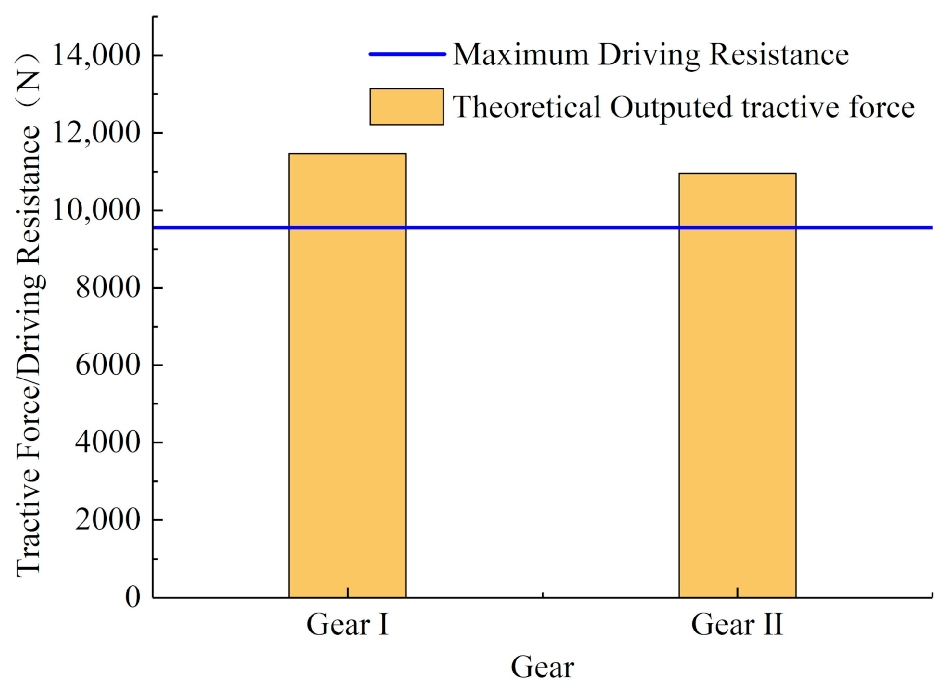
According to Formula (7), the maximum drive torque outpoured by tractor in the Gear I and Gear II can be converted into the theoretical tractive force, and then the theoretical tractive force outputted by tractor in the Gear I and Gear II was compared with the traction resistance overcame by the tractor ploughing on the slope. The compared results are shown in Figure 8.
According to Figure 8, the theoretical outputted maximum tractive force of the tractor in the Gear I was 11,456.3 N, and the theoretical outputted maximum tractive force of the tractor in the Gear II was 10,959.2 N, which were larger than the traction resistance of 983.7 N experienced by the tractor ploughing on the slope.
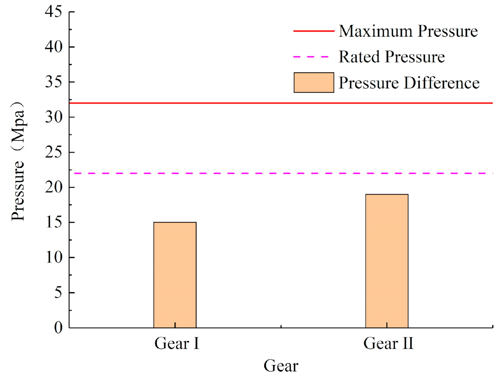
The working pressure of the HST should not exceed maximum pressure when working and cannot exceed the rated value when constantly performing heavy work. The inlet and outlet pressures of the hydraulic motor of the HST in the traction performance tests in the Gear I and Gear II of the tractor were compared with the rated pressure and maximum pressure of the system, and the comparison results are shown in Figure 9.
The maximum pressure difference between the inlet and outlet of the hydraulic motor was 15 MPa and 19 MPa in the traction performance tests of Gear I and Gear II respectively, which were lower than the rated pressure, 21 MPa, and lower than the maximum pressure, 32 MPa. The designed drive system can meet the requirement of the tractor constantly ploughing at slope in a long time. The changes in the parameters of the drive system in Gear II were obviously greater than those in Gear I because the transmission ratio for Gear II was small, the engine load was higher, and the output power was larger, although the load torque of the driving wheel was the same.
Traction performance test show that the maximum outputted torque of the designed drive system of the tractor is larger than the drive torque needed for the slope ploughing, the drive system has power reverse, which can meet the requirements of a tractor constantly working with a larger load.

3.2. Test Results of the Initial Acceleration Performance

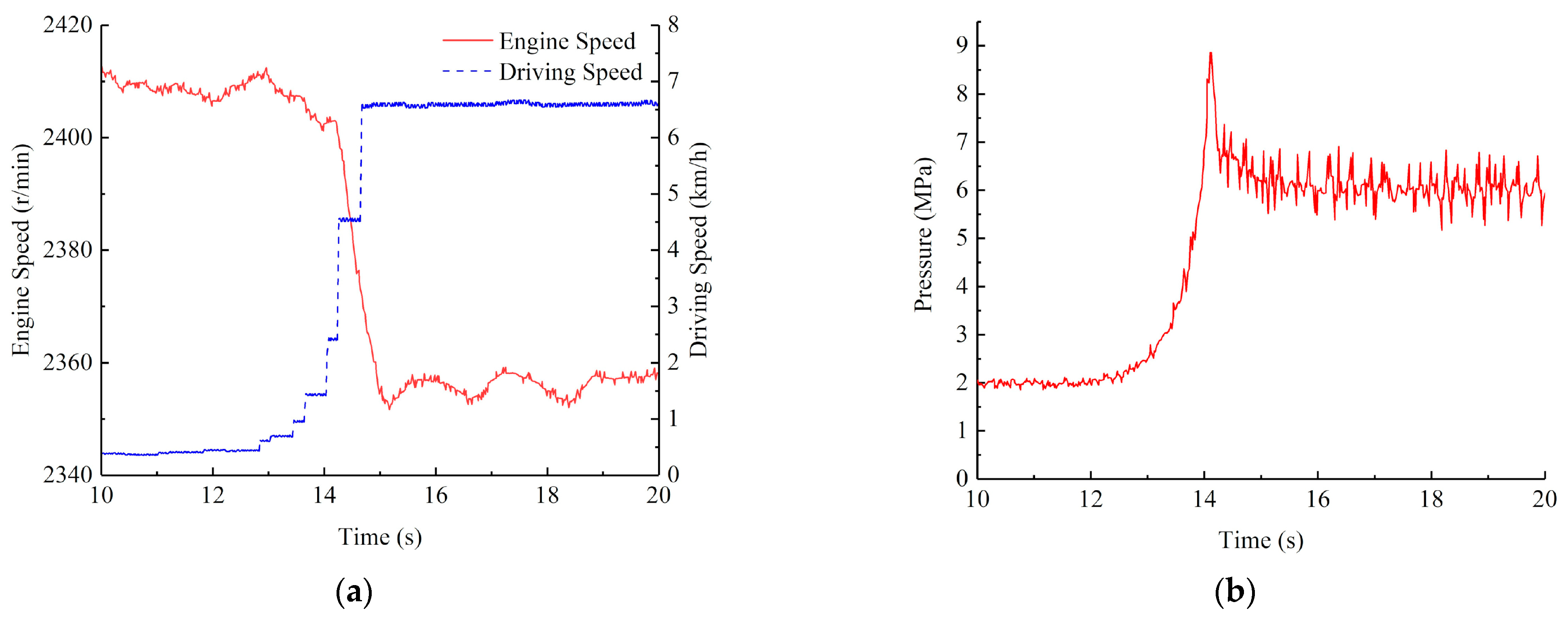
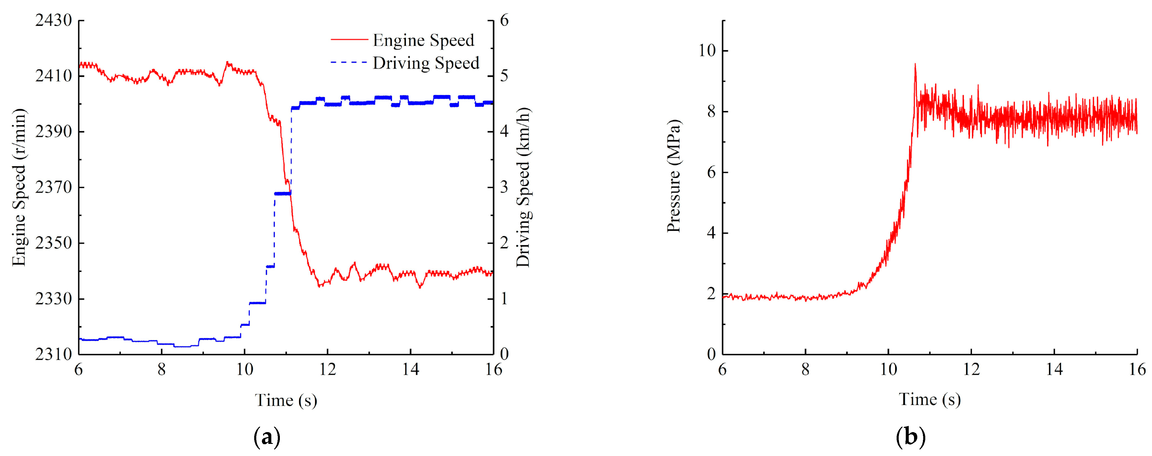
The test results for the acceleration performance when starting on flat ground are shown in Figure 10, Figure 11 and Figure 12. Figure 10a, Figure 11a, and Figure 12a show that the driving speed gradually increased with increasing swash plate angle of the HST variable pump. In the process of starting and accelerating, the engine speed first decreased and then remained stable. When the system reached stability, the engine speeds in Gear I, Gear II, and Gear III were approximately 2370 r/min, 2355 r/min, and 2335 r/min, respectively, and the maximum driving speeds were approximately 4.65 km/h, 6.58 km/h, and 8.57 km/h, respectively. Figure 10b, Figure 11b, and Figure 12b show that the pressure difference between the inlet and outlet of the motor first increased sharply and then decreased and finally stabilized at approximately 5.0 MPa, 6.0 MPa, and 8.0 MPa with the increase of the swash plate angle of the HST variable pump.
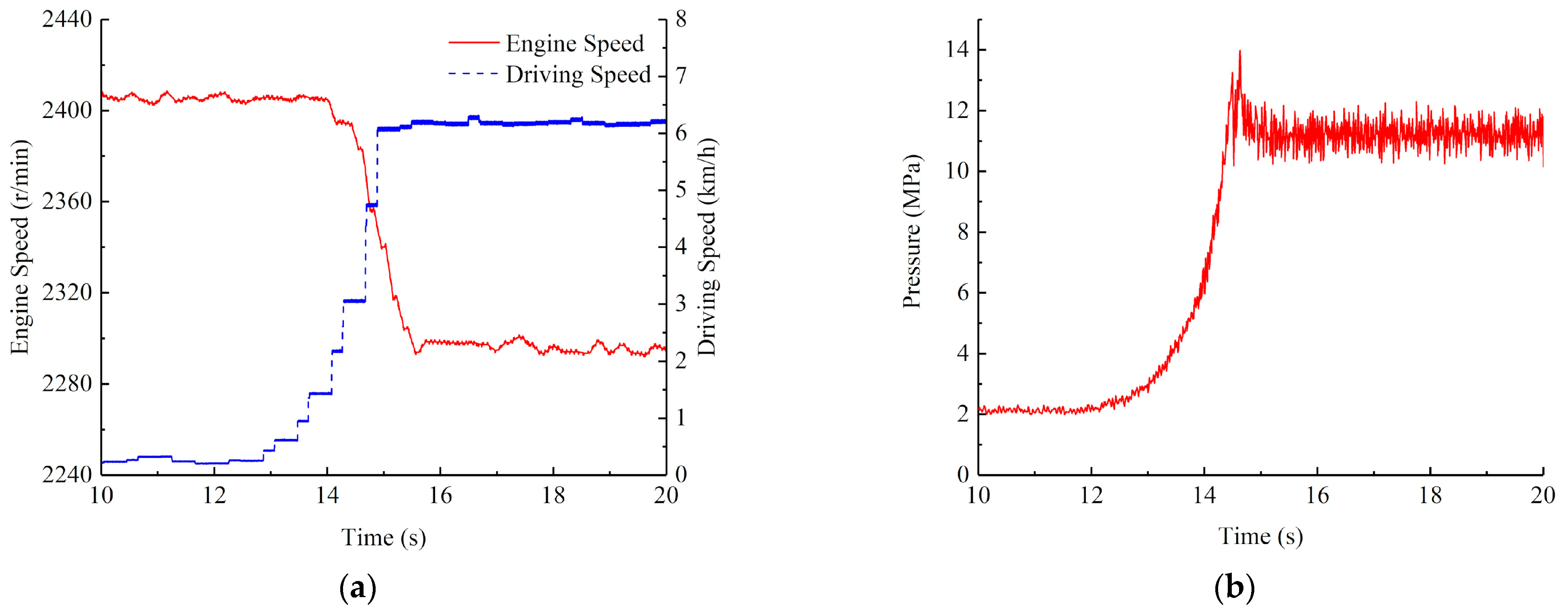
The test results of the starting acceleration performance on the slope are shown in Figure 13, Figure 14 and Figure 15. Figure 13a, Figure 14a, and Figure 15a show that the driving speed gradually increased with increasing swash plate angle of the HST variable pump. In the process of starting and accelerating, the engine speed first decreased and then remained stable. When the system reached a stability, the engine speeds at Gear I, Gear II, and Gear III were approximately 2330 r/min, 2280 r/min, and 2250 r/min, respectively, and the maximum driving speeds were approximately 4.55 km/h, 6.25 km/h, and 8.28 km/h, respectively. Figure 13b, Figure 14b, and Figure 15b show that in the process of starting and accelerating in Gear I, Gear II, and Gear III on the slope, the inlet and outlet pressure difference of the motor first increased sharply and then decreased, and finally stabilized at approximately 8.0 MPa, 12.0 MPa, and 14.0 MPa, respectively, with the increase of the swash plate angle of the HST variable pump.
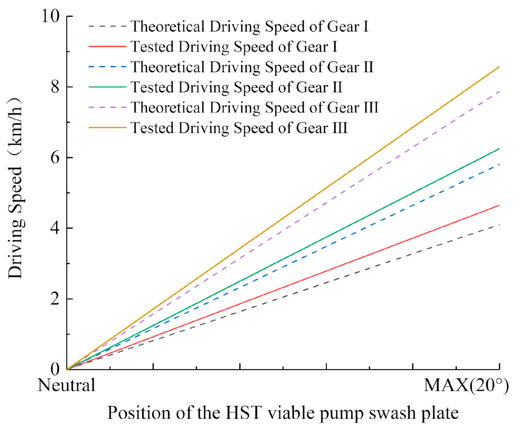
In the process of the acceleration performance on flat ground, the driving speeds of Gear I, Gear II, and Gear III were in the ranges of 0–4.65 km/h, 0–6.25 km/h, and 0–8.28 km/h respectively. The theoretical calculated results of the driving speed of Gear I, Gear II, and Gear III were in the ranges of 0–4.10 km/h, 0–5.81 km/h, and 0–7.87 km/h respectively. The comparison of the range of driving speed between the tested result and the theoretical calculation result can be seen in Figure 16. There is little difference between the tested result and the theoretical calculation result, which can indicate that the designed drive system can meet the requirement of the driving speed of the hillside crawler tractor in the different working conditions.
In the process of the acceleration performance on the slope, the maximum speeds of Gear I, Gear II, and Gear III were 4.55 km/h, 6.25 km/h, and 8.28 km/h respectively. This was slightly lower than the maximum driving speeds of the tractor in Gear I, Gear II, and Gear III on flat ground. This difference is not considered significant, indicating that a larger load has little effect on the maximum driving speed of the tractor, and the drive system has a good speed consistency.
In the process of the acceleration performance on flat ground and the slope, the time for the tractor reaching the maximum speed in each Gear was less than 3 s, and the pressure difference between the inlet and outlet of the hydraulic motor could e restored quickly after sharp fluctuations, which can indicate that the designed drive system has the advantage of fast response and good stability.

4. Conclusions

The scheme of the drive system based on the HST for hillside crawler tractors is proposed as the best configuration. The driving resistance and driving power of the tractor under typical working conditions are calculated. Parameter matching for the key parts of the drive system, such as the three-cylinder diesel engine, HST, and driving rear axle, was completed. On this basis, the drive system test bench was built, and dynamic performance tests of the drive system for the traction performance and starting acceleration performance on flat and sloped ground were carried out. In the traction performance test, when the engine was at the maximum torque point of 1700 r/min, the maximum theoretical tractive force outputted by the tractor in Gear I was 114,563 N, and the maximum theoretical tractive force outputted by the tractor in Gear II was 10,959.2 N, which were larger than the traction resistance of 9550.6 N experienced by the hillside tractor ploughing on the slope. In the starting acceleration performance test, the driving speed could gradually increase with increasing displacement of the variable pump. When the tractor was driving on flat ground, the maximum driving speeds of Gear I, Gear II, and Gear III were 4.65 km/h, 6.58 km/h, and 8.57 km/h, respectively, which are close to the theoretical calculation values. When the tractor was driving on a 15° slope, the maximum driving speeds of Gear I, Gear II, and Gear III were 4.55 km/h, 6.25 km/h, and 8.28 km/h, respectively, which are slightly lower than the maximum driving speeds of each Gear on flat ground. According to the theoretical calculation and test analysis, the matching of the components of the drive system was reasonable, and the speed consistency of the drive system was good; we conclude that the designed drive system can meet the dynamic performance requirements of a hillside crawler tractor.

5. Patents

A Patent has been applied in China for the test bench system reported in this manuscript (Patent No. CN208534878U and Application No. 2018212586741).

Author Contributions

Investigation, G.Z., G.C., Y.Z. and H.N.; writing—original draft preparation, Z.L. and G.C.; writing—review and editing, G.Z.; supervision, F.Y. and Z.L.; and project administration, F.Y. All authors have read and agreed to the published version of the manuscript.

Funding

This research received external funding from the National Key Research and Development Plan Program (2016YFD0200700 and 2016YFD0700503) and the Major Science and Technology Project of Shaanxi Province of China (Program No. 2020zdzx03-04-01).

Institutional Review Board Statement

Not applicable.

Informed Consent Statement

Not applicable.

Data Availability Statement

The data presented in this study are available on demand from the second author at (zhangguoqiang930@nwafu.edu.cn).

Acknowledgments

The authors thank the National Key Research and Development Plan Program (2016YFD0200700 and 2016YFD0700503) and the Major Science and Technology Project of Shaanxi Province of China (Program No. 2020zdzx03-04-01) for funding. We also thank the anonymous reviewers for providing critical comments and suggestions that improved the manuscript.

Conflicts of Interest

The authors declare no conflict of interest.

References

  1. Luo, X.W. How to Develop the Agricultural Mechanization in Hilly Regions. Agric. Mach. Sci. Technol. Dev. 2011, 2, 17–20. (In Chinese) [Google Scholar] [CrossRef]
  2. Wang, Y.J.; Yang, F.Z.; Pan, G.T.; Liu, H.Y.; Liu, Z.J.; Zhang, J.Q. Design and testing of a small remote-control hillside tractor. Trans. ASABE 2014, 57, 363–370. [Google Scholar] [CrossRef]
  3. Luo, X.W.; Liao, J.; Hu, L.; Zhang, Y.; Zhou, Z.Y. Improving agricultural mechanization level to promote agricultural sustainable development. Trans. Chin. Soc. Agric. Eng. 2016, 32, 1–11. (In Chinese) [Google Scholar] [CrossRef]
  4. Sun, J.B.; Meng, C.; Zhang, Y.Z. Design and physical model experiment of an attitude adjustment device for a crawler tractor in hilly and mountainous regions. Inf. Process. Agric. 2020, 7, 466–478. [Google Scholar] [CrossRef]
  5. Wang, Y.J.; Liu, Y.C.; Yang, F.Z. Development and test of tiny remotely controlled electric tractor for greenhouses. Trans. Chin. Soc. Agric. Eng. 2012, 28, 23–29. (In Chinese) [Google Scholar]
  6. Molari, G.; Bellentani, L.; Guarnieri, A. Performance of an agricultural tractor fitted with rubber tracks. Biosys. Eng. 2012, 111, 57–63. [Google Scholar] [CrossRef]
  7. Dasgupta, K.; Mandal, S.K.; Pan, S. Dynamic analysis of a low speed high torque hydrostatic drive using steady-state characteristics. Mech. Mach. Theory 2012, 52, 1–17. [Google Scholar] [CrossRef]
  8. Kim, D.M.; Kim, S.C.; Noh, D.K.; Jang, J.S. Jerk phenomenon of the hydrostatic transmission through the experiment and analysis. Int. J. Automot. Technol. 2015, 16, 783–790. [Google Scholar] [CrossRef]
  9. Jivkov, V.; Draganov, V. Theoretical Study and Experimental Validation of a Hydrostatic Transmission Control for a City Bus Hybrid Driveline with Kinetic Energy Storage. Energies 2018, 11, 2200. [Google Scholar] [CrossRef] [Green Version]
  10. Wang, Y.; Zhang, Y.L.; Qin, X.Q.; Xu, M. Research Status and Development Trend on Vehicle Hydrostatic Transmission Hydraulic System. Mach. Hydraul. 2015, 43, 149–155. (In Chinese) [Google Scholar] [CrossRef]
  11. Li, S.; Chen, J.F.; Dong, H. Selection and design of HST for medium and small horsepower tractors. Agric. Dev. Equip. 2018, 5, 81–82. [Google Scholar] [CrossRef]
  12. Kim, W.S.; Kim, Y.-J.; Kim, Y.-S.; Baek, S.-Y.; Baek, S.-M.; Lee, D.-H.; Nam, K.-C.; Kim, T.-B.; Lee, H.-J. Development of Control System for Automated Manual Transmission of 45-kW Agricultural Tractor. Appl. Sci. 2020, 10, 2930. [Google Scholar] [CrossRef]
  13. Wang, G.; Song, Y.; Wang, J.; Chen, W.; Cao, Y.; Wang, J. Study on the Shifting Quality of the CVT Tractor under Hydraulic System Failure. Appl. Sci. 2020, 10, 681. [Google Scholar] [CrossRef] [Green Version]
  14. Murakami, N.; Ito, A.; Will, J.D. Development of a teleoperation system for agricultural vehicles. Comput. Electron. Agric. 2008, 63, 81–88. [Google Scholar] [CrossRef]
  15. Wan, I.; Yong, W.L.; Razali, M.H. Development of autonomous bio-production vehicle for agriculture. Int. J. Agric. Sci. 2010, 2, 21–27. [Google Scholar] [CrossRef] [Green Version]
  16. Takai, R.; Yang, L.L.; Noguchi, N. Development of a crawler-type robot tractor using RTK-GPS and IMU. Eng. Agric. Environ. Food 2014, 7, 143–147. [Google Scholar] [CrossRef]
  17. Karl-Erik, R. Hydrostatic Drives in Heavy Mobile Machinery-New Concepts and Development Trends. SAE Trans. 1998, 107, 232–238. [Google Scholar]
  18. Comellas, M.; Pijuan, J. Analysis of a hydrostatic transmission driveline for its use in off-road multiple axle vehicles. J. Terramech. 2012, 49, 245–254. [Google Scholar] [CrossRef]
  19. Xiao, L.; Zhi Gu APP. Top 10 grain harvesters in China International Agricultural Machinery Exhibition 2019. Farm. Mach. 2019, 11, 40–42. (In Chinese) [Google Scholar] [CrossRef]
  20. Yang, H.Y.; Wang, H.B.; Zhang, L.X.; Zhao, Y.K. Application of hydraulic drive system in wheeled grain combine harvester. Tractor. Farm. Transp. 2019, 46, 10–12. (In Chinese) [Google Scholar]
  21. Bhamodkar, M.A.; Bhende, S.M.; Khambalkar, V.P. Hydrostatic drive system for sorghum harvester. New Agric. 2006, 2, 207–214. [Google Scholar]
  22. Chen, S.Y.; Du, Y.F.; Xie, B.; Song, Z.H.; Mao, E.R.; Chen, Y. Design and performance analysis of drive system for high clearance self-propelled corn detasseling machine. Trans. Chin. Soc. Agric. Eng. 2016, 32, 10–17. (In Chinese) [Google Scholar] [CrossRef]
  23. Zou, F.; Kang, J.J.; Xiao, M.H. Hydrostatic driving system for self-propelled sprayer. Int. Agric. Eng. J. 2017, 26, 11–17. [Google Scholar]
  24. Zhao, J.H.; Xu, L.Y.; Zhang, J.Q. Research and application status of hydrostatic driving technology of Non-road vehicles. Tractor. Farm. Transp. 2018, 45, 8–13. (In Chinese) [Google Scholar]
  25. Luoyang Tractor Research Institute, Ministry of Machinery and Electronics Industry, China. Tractor Design Manual, 1st ed.; China Machine Press: Beijing, China, 1994; Volume 1. (In Chinese)
  26. Luoyang Tractor Research Institute, Ministry of Machinery and Electronics Industry, China. Mechanical Engineering Manual, 1st ed.; China Machine Press: Beijing, China, 1978; Volume 70. (In Chinese)
  27. Wang, M.H. Thoughts on accelerating the development of Agricultural Mechanization in southern and hilly areas. South. Agric. Mach. 2015, 8, 3–7. (In Chinese) [Google Scholar] [CrossRef]
  28. Wang, Y. Hydrostatic Driving of Vehicles and Walking Machinery; Chemical Industry Press: Beijing, China, 2014; pp. 272–290. (In Chinese) [Google Scholar]
  29. Xu, L.Y.; Liu, M.N.; Zhou, Z.L. Design of drive system for series hybrid electric tractor. Trans. Chin. Soc. Agric. Eng. 2014, 30, 11–18. (In Chinese) [Google Scholar] [CrossRef]
  30. Chen, L.Q.; Zhan, Q.F.; Wang, W.W.; Huang, X.; Zheng, Q. Design and Experiment of Electric Drive System for Pure Electric Tractor. Trans. Chin. Soc. Agric. Mach. 2018, 49, 388–394. (In Chinese) [Google Scholar] [CrossRef]
  31. Zhao, L.J.; Wei, Y.Y.; Liu, Q.H. Hierarchical control of engine-variable pump-variable motor drive system. J. B Univ. Aeronaut. Astronaut. 2015, 41, 1416–1421. (In Chinese) [Google Scholar] [CrossRef]
  32. Lu, Y.X. Technical Handbook for Hydraulics and Pneumatics; China Machine Press: Beijing, China, 2002; pp. 470–541. (In Chinese) [Google Scholar]
  33. Xie, B.; Zhang, C.; Chen, S.; Mao, E.R.; Du, Y.F. Transmission Performance of Two-wheel Drive Electric Tractor. Trans. Chin. Soc. Agric. Mach. 2015, 46, 8–13. (In Chinese) [Google Scholar] [CrossRef]
  34. Luo, Q.G.; Zhang, Y.F.; Yuan, W. Comprehensive Evaluation of Power-train Performance for Tracked Vehicles. Acta Armamentarii 2005, 26, 413–417. (In Chinese) [Google Scholar] [CrossRef]
  35. Wei, L.; Liu, H.; Chen, H.; Xu, Y.; Zhao, Z. Research on parameter optimisation of tracked vehicle transmission system based on genetic algorithm. Int. J. Autom. Logist. 2021, 3, 169. [Google Scholar] [CrossRef]
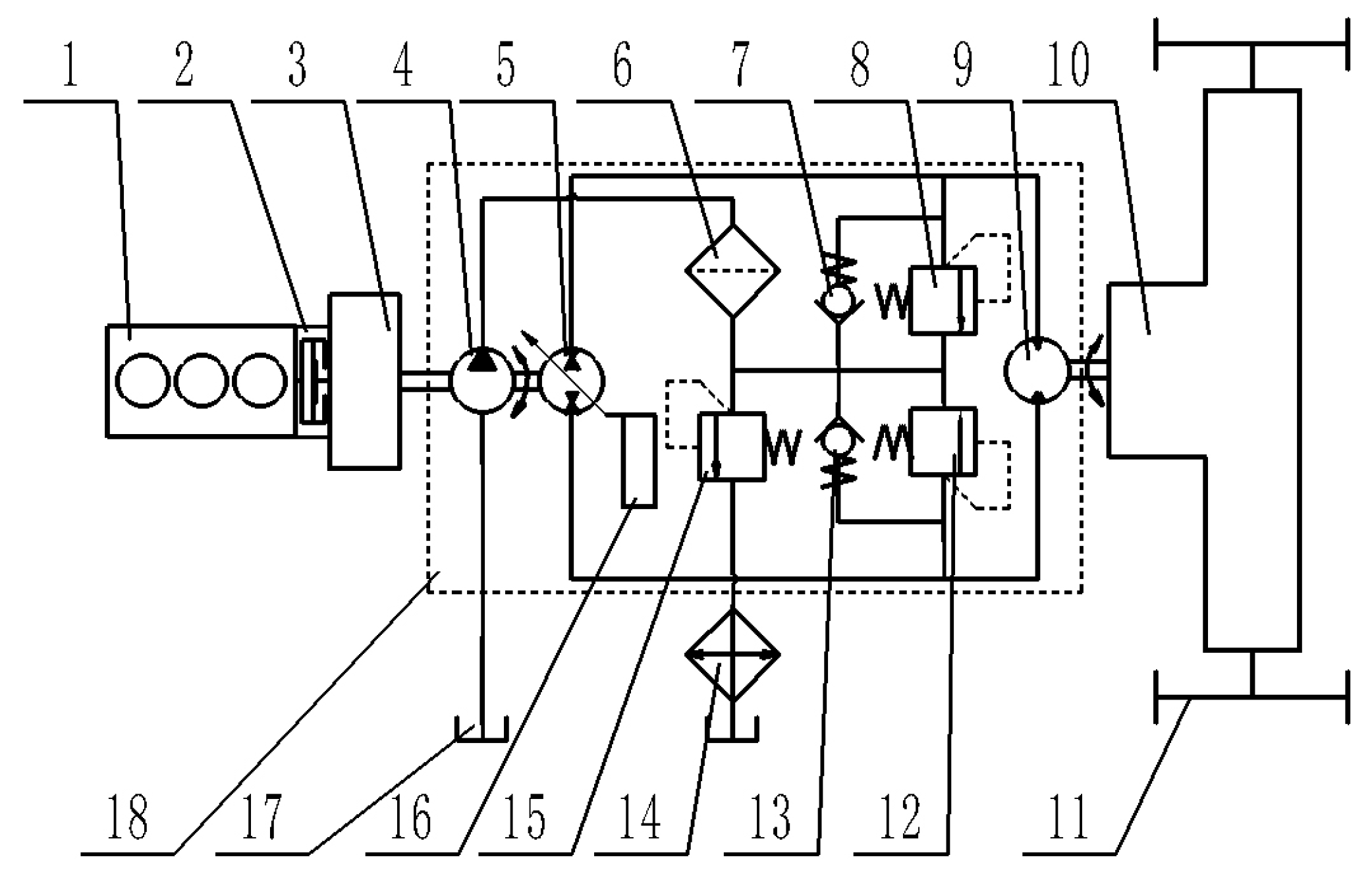
Figure 1. Sketch of the structure of the drive system of the hillside crawler tractor. 1. Engine; 2. Clutch; 3. Transfer case; 4. Charge pump; 5. Variable pump; 6. Filter; 7. Check valve; 8. Overflow valve; 9. Bidirectional hydraulic motor; 10. Drive rear axle; 11. Driving wheel; 12. Overflow valve; 13. Check valve; 14. Radiator; 15. Overflow valve; 16. Swashplate adjusting mechanism; 17. Oil tank; and 18. Hydrostatic transmission (HST).
Agriculture 11 00466 g001
Figure 2. Working force diagram of the hillside crawler tractor. Note: Ft is the driving resistance, (N); Ff is the rolling resistance, (N); Fp is the ramp resistance, (N); Fg is the drive resistance, (N); W is the normal load (N); FN is the supporting force from the ground (N); V is the working speed of the tractor, (km/h); O is the center of gravity of the tractor.
Agriculture 11 00466 g002
Figure 3. Structural components of the drive system test bench. Note: HST is the abbreviations of the hydrostatic transmission.
Agriculture 11 00466 g003
Figure 4. Test bench assembly drawing. 1. Hydraulic control system; 2. Engine; 3. Drive rear axle; 4. HST; 5. Fuel tank; 6. Gear Increaser; 7. Flywheel; 8. Speed & torque sensor; 9. Hydraulic pump; and 10. Cooler.
Agriculture 11 00466 g004
Figure 5. Test bench. 1. Hydraulic control system; 2. Engine; 3. Drive rear axle; 4. HST; 5. Fuel tank; 6. Gear Increaser; 7. Flywheel; 8. Speed & torque sensor; 9. Hydraulic pump; and 10. Data acquisition system 11. Control System. 12. Throttle Adjusting Mechanism.
Agriculture 11 00466 g005
Figure 6. Schematic diagram of the load system.
Agriculture 11 00466 g006
Figure 7. Test result of the traction performance. (a) change of the load torque; (b) change of the inlet and outlet pressure difference of the hydraulic motor; (c) change of the engine speed; and (d) change of the driving speed.
Agriculture 11 00466 g007
Figure 8. Analysis of the tractive force.
Agriculture 11 00466 g008
Figure 9. Analysis of the pressure difference between the inlet and outlet of the hydraulic motor.
Agriculture 11 00466 g009
Figure 10. Parameters when starting on flat ground in Gear I: (a) change of the engine speed and driving speed; (b) change of the inlet and outlet pressure difference of the motor.
Agriculture 11 00466 g010
Figure 11. Parameters when starting on flat ground in Gear II: (a) change of the engine speed and driving speed; (b) change of the inlet and outlet pressure difference of the motor.
Agriculture 11 00466 g011
Figure 12. Parameters when starting on flat ground in Gear III: (a) change of the engine speed and driving speed; (b) change if the inlet and outlet pressure difference of the hydraulic motor.
Agriculture 11 00466 g012
Figure 13. Parameters when starting on slope in Gear I: (a) change of the engine speed and driving speed; (b) change of the inlet and outlet pressure difference of the hydraulic motor.
Agriculture 11 00466 g013
Figure 14. Parameters when starting on slope in Gear II: (a) change in the engine speed and driving speed; (b) inlet and outlet pressure difference of the hydraulic motor.
Agriculture 11 00466 g014
Figure 15. Parameters when starting on slope in Gear III: (a) change of the engine speed and driving speed; (b) change of the inlet and outlet pressure difference of the hydraulic motor.
Agriculture 11 00466 g015
Figure 16. Comparison of the range of the driving speed of the tractor between the tested result and the theoretical calculation result.
Agriculture 11 00466 g016
Table 1. Theoretical working speed for the main operation of the crawler tractor.
Operation ItemsPloughingRotary TillageHarrow, SuppressSeedingCultivation and Plant ProtectionTransplanting and Ditching
Speed range
(km/h)
3.5–72–34–85–93–70.5–2.5
Table 2. Main technical parameters of the hillside crawler tractor.
NameParameterNameParameter
Total weight (kg)Approximately 1300Number of shares2
Working speed (km/h)0–8Maximum working gradient (°)15
Radius of the driving wheel (mm)103Ploughing depth (mm)250
Table 3. Loads and power of the hillside crawler tractor under typical working conditions.
Working ConditionTask
Type
Resistance
Coefficient
Maximum
Speed
(km/h)
Rolling
Resistance
(N)
Traction
Resistance
(N)
Driving
Resistance
(N)
Drive
Torque
(N·m)
Power
(kW)
Flat groundDriving0.068.0764.401656.2170.63.68
Seeding0.077.0891.81875.03658.6376.87.11
Ploughing0.076.0891.84500.06283.6647.210.47
SlopeDriving0.066.0764.404953.6510.28.26
Seeding0.075.0861.41875.06952.6713.99.62
Ploughing0.074.5861.44500.09550.6983.711.94
Note: (1) The inner resistance of the tractor is 891.8 N. (2) When the tractor driving, seeding, or ploughing on flat ground, the slope resistance is 0 N; when the tractor driving, seeding, or ploughing on a slope, the slope resistance is 3297.4 N.
Table 4. Main performance parameters of the ZN390B diesel engine.
ModelRated Power
(kW)
Rated Speed
(r/min)
Maximum Torque
(N·m)
Displacement
(L)
ZN390B26.5240024001.908
Table 5. Main parameters of the LY-HPVMF-28-L-02 type HST.
SpecificationsParameter
Variable pump displacement (mL/r)0–28
Motor displacement (mL/r)28
Charge pump Displacement (mL/r)7
Maximum input speed (r/min)3000
Output speed (r/min)0–3000
Rated pressure (MPa)21
Maximum pressure (MPa)32
Theoretical rated output torque (N·m)93.6
Maximum output torque (N·m)151.6
Operating temperature range (°C)−20–80
Theoretical total efficiency (%)≥73
Table 6. Main parameters of the XL-80 driving rear axle.
TypeMaximum Input Speed (r/min)Transmission RatioGear Speed RatioSteering ModeLubricating Oil
XL-80 23.36
24000.816.46Jaw clutchAnti-wear (68#)
12.16
Note: Symbol “68#” is the grade of the viscosity of the lubricating oil.
Table 7. Tractor speed in each gear.
GearGear IGear IIGear III
Theoretical set speed
(km/h)
0–40–60–8
Driving speed after checking
(km/h)
0–4.10–5.810–7.87
Table 8. Type and parameters of the main components of the load system.
NameTypeMain ParameterNumerical Value
Gear Increaser I Actual transmission ratio14.75
ZLY-125Nominal input speed (R/min)1500
Nominal output speed (R/min)107
Gear Increaser II Actual transmission ratio6.3
ZLY-125Nominal input speed (R/min)1500
Nominal output speed (R/min)240
Loading
Hydraulic Pump
CBG2040-BFPRNominal displacement (mL/r)40
Rated pressure (MPa)20
FlywheelZS1105Mass (kg)25
Outer diameter (mm)450
CoolerGLC-2.6Cooling area (m2)2.6
Heat transfer coefficient (W/(m2 °C))330
Speed & Torque sensorTL-303Range (N·m)−200–+200
measurement accuracy0.5%
Publisher’s Note: MDPI stays neutral with regard to jurisdictional claims in published maps and institutional affiliations.