
Design and Experiment of the Automatic Laying System for Rice Seedling Tray


Abstract
:1. Introduction
2. Materials and Methods
2.1. Materials
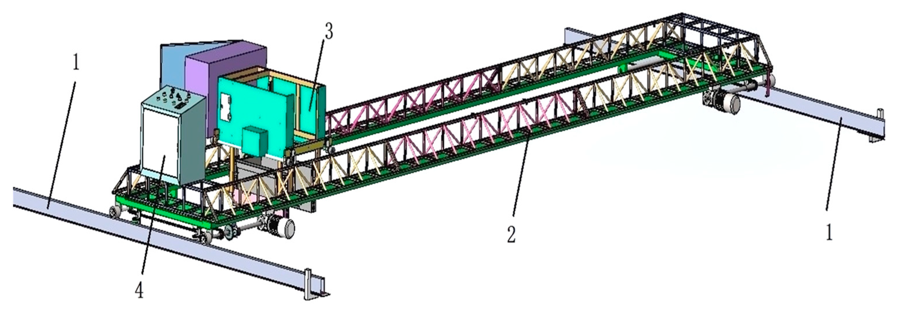
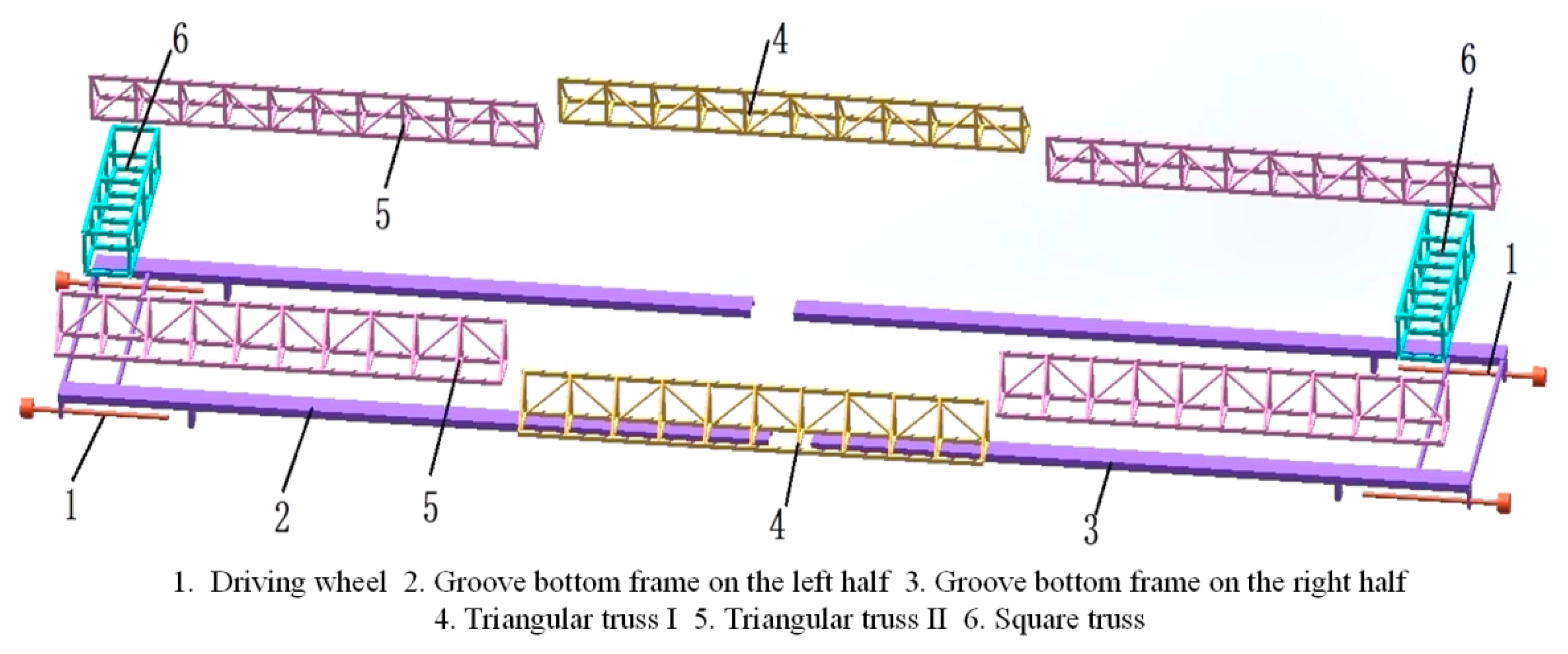
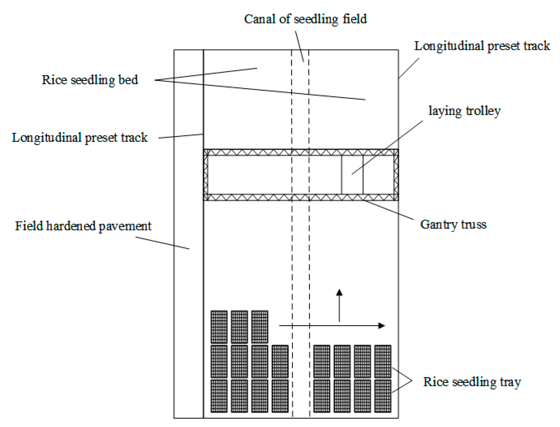
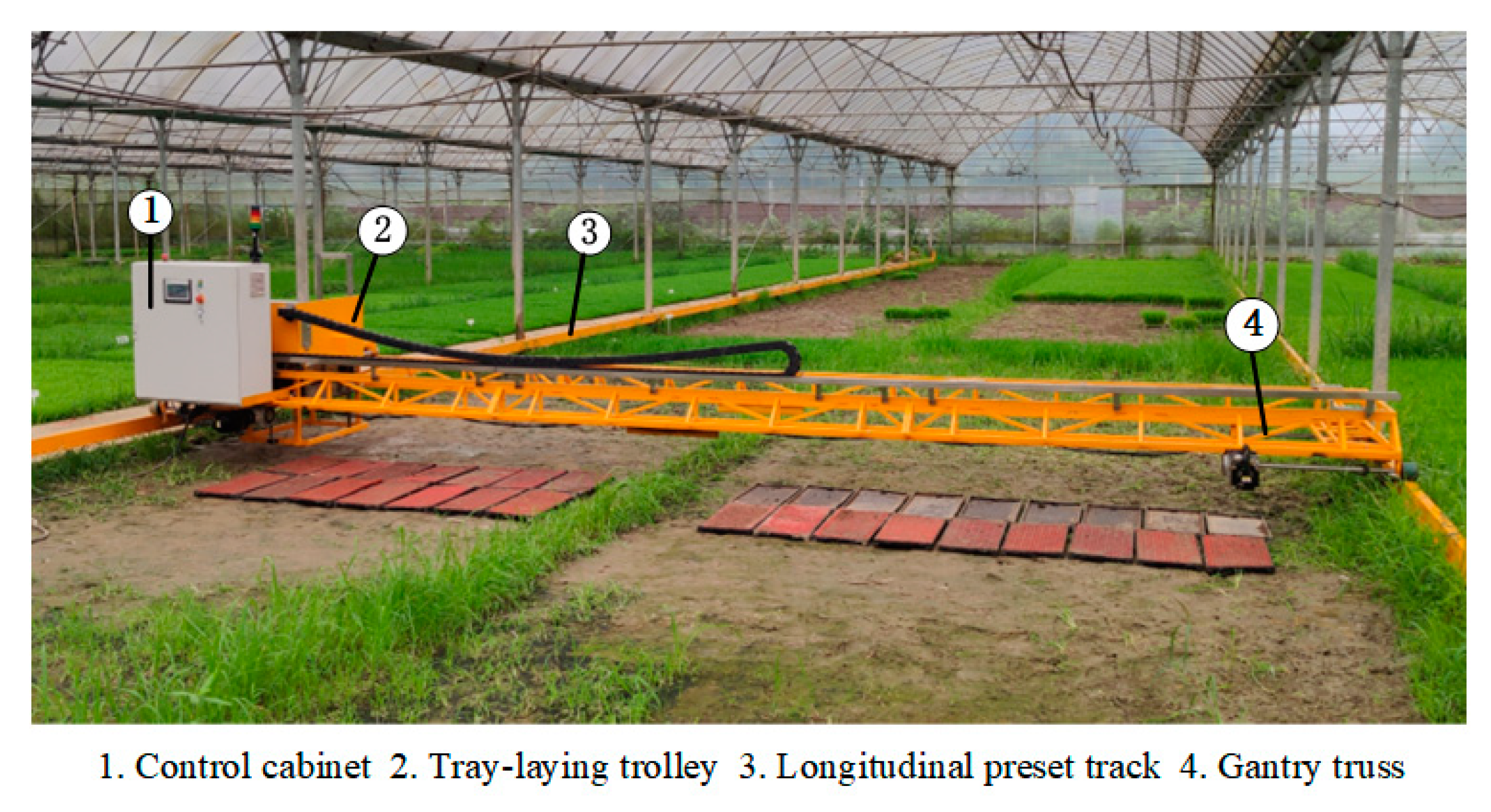
2.1.1. Gantry Truss
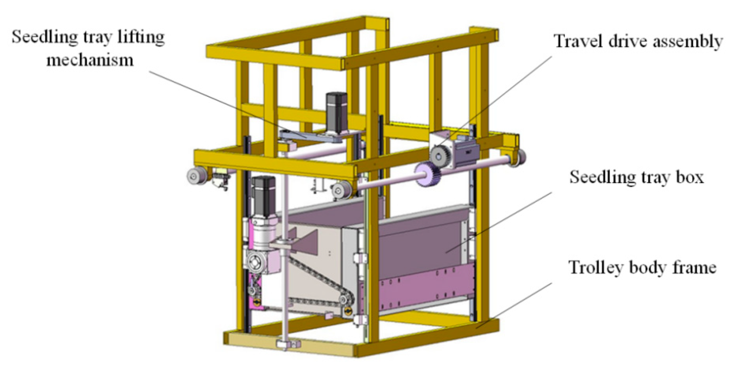
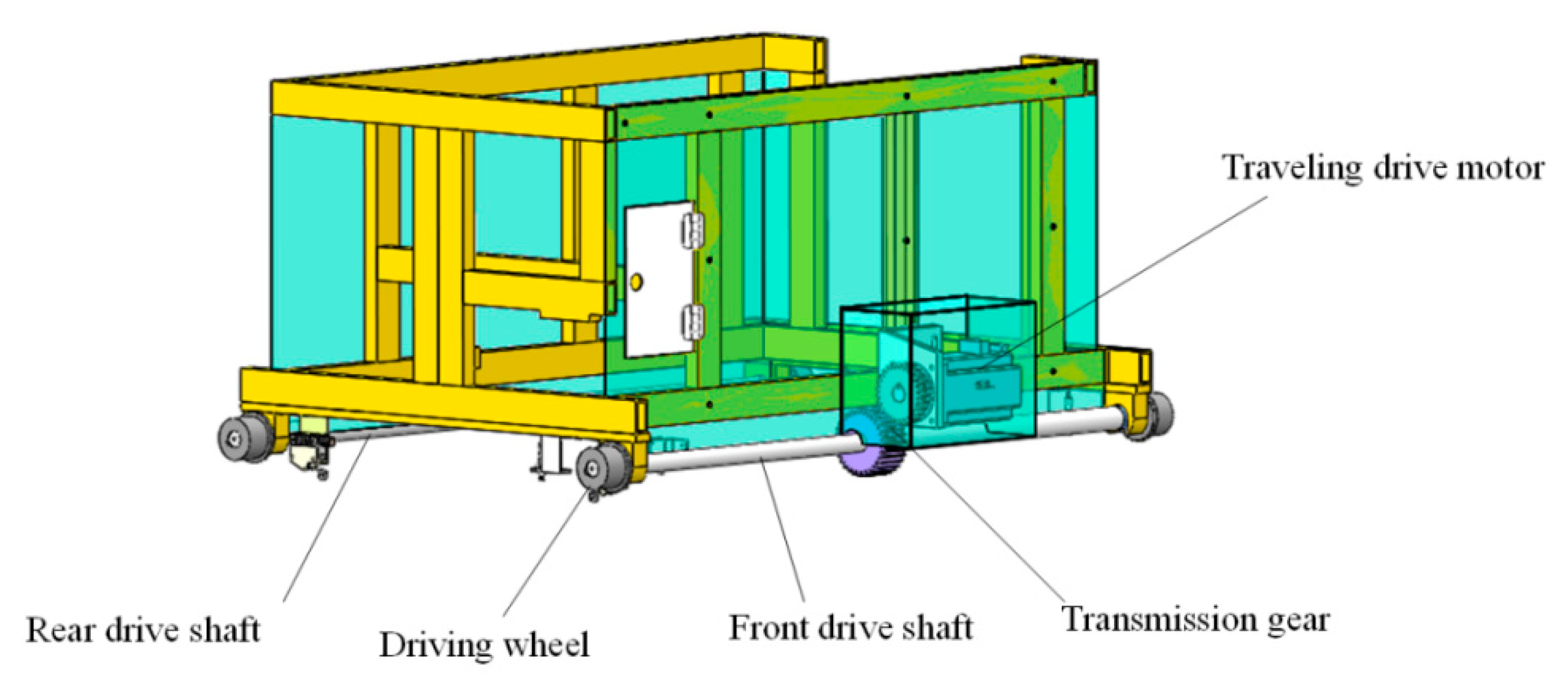
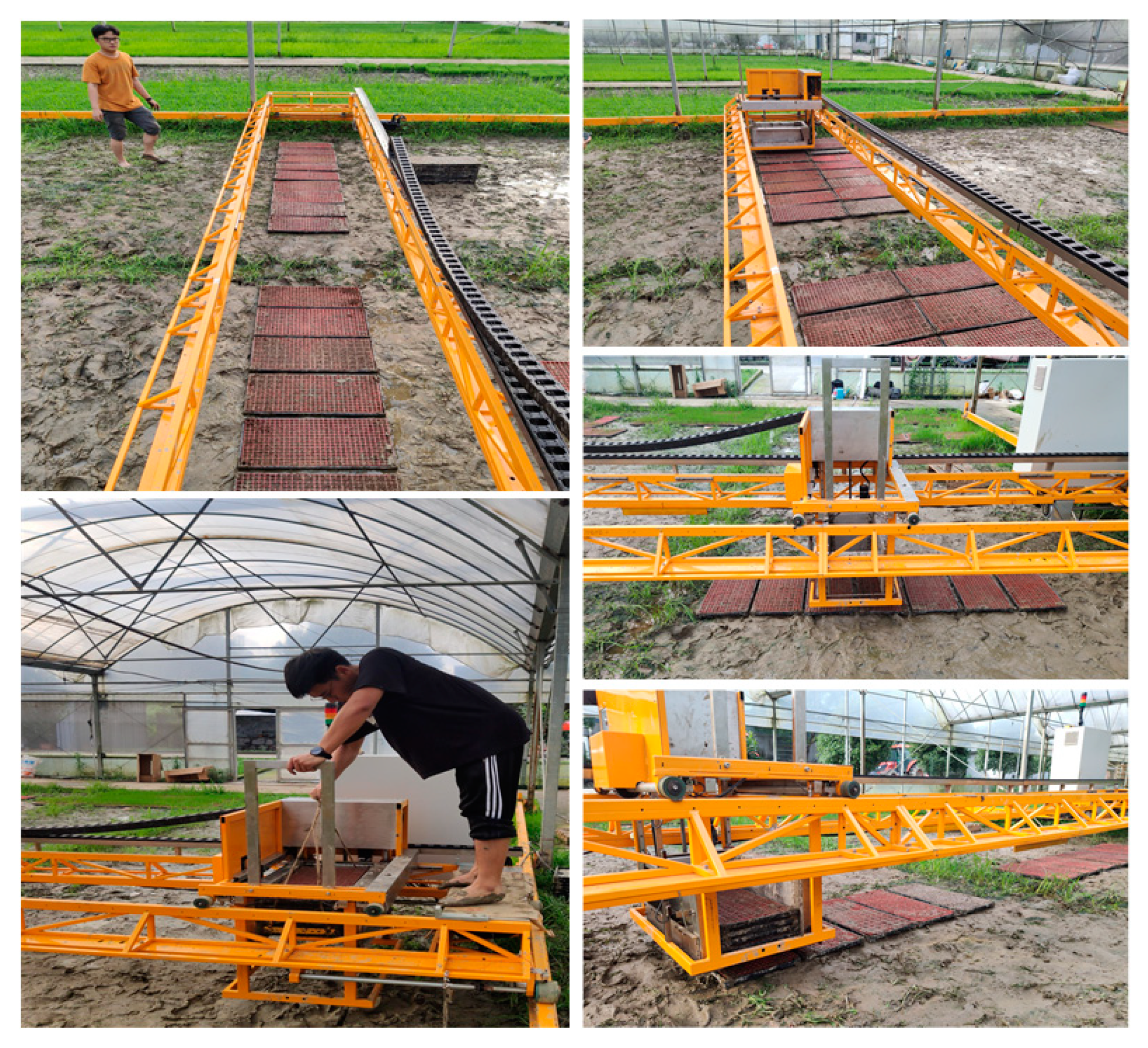
2.1.2. Tray Laying Trolley
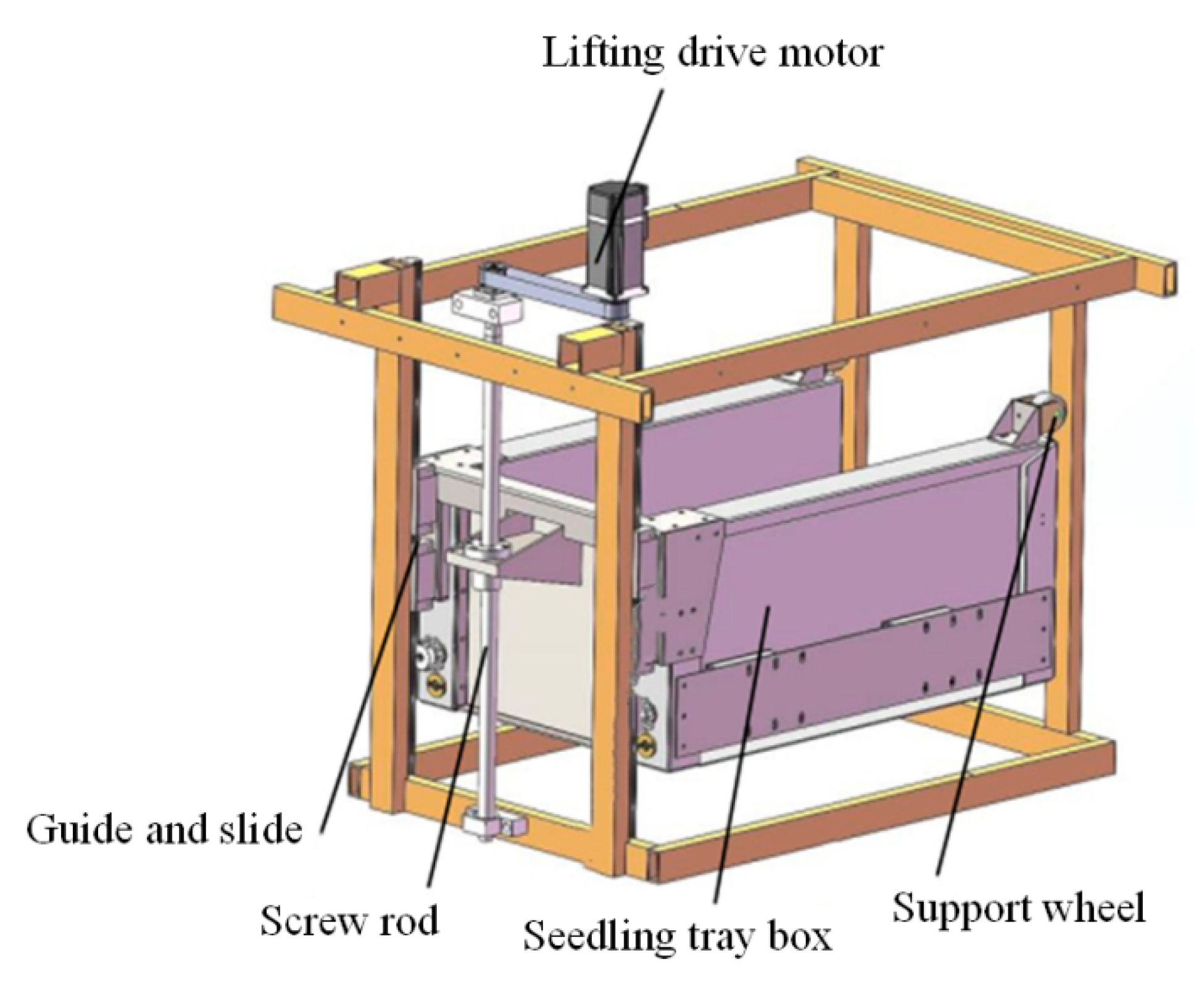
2.1.3. Tray Laying Mechanism
2.2. Method
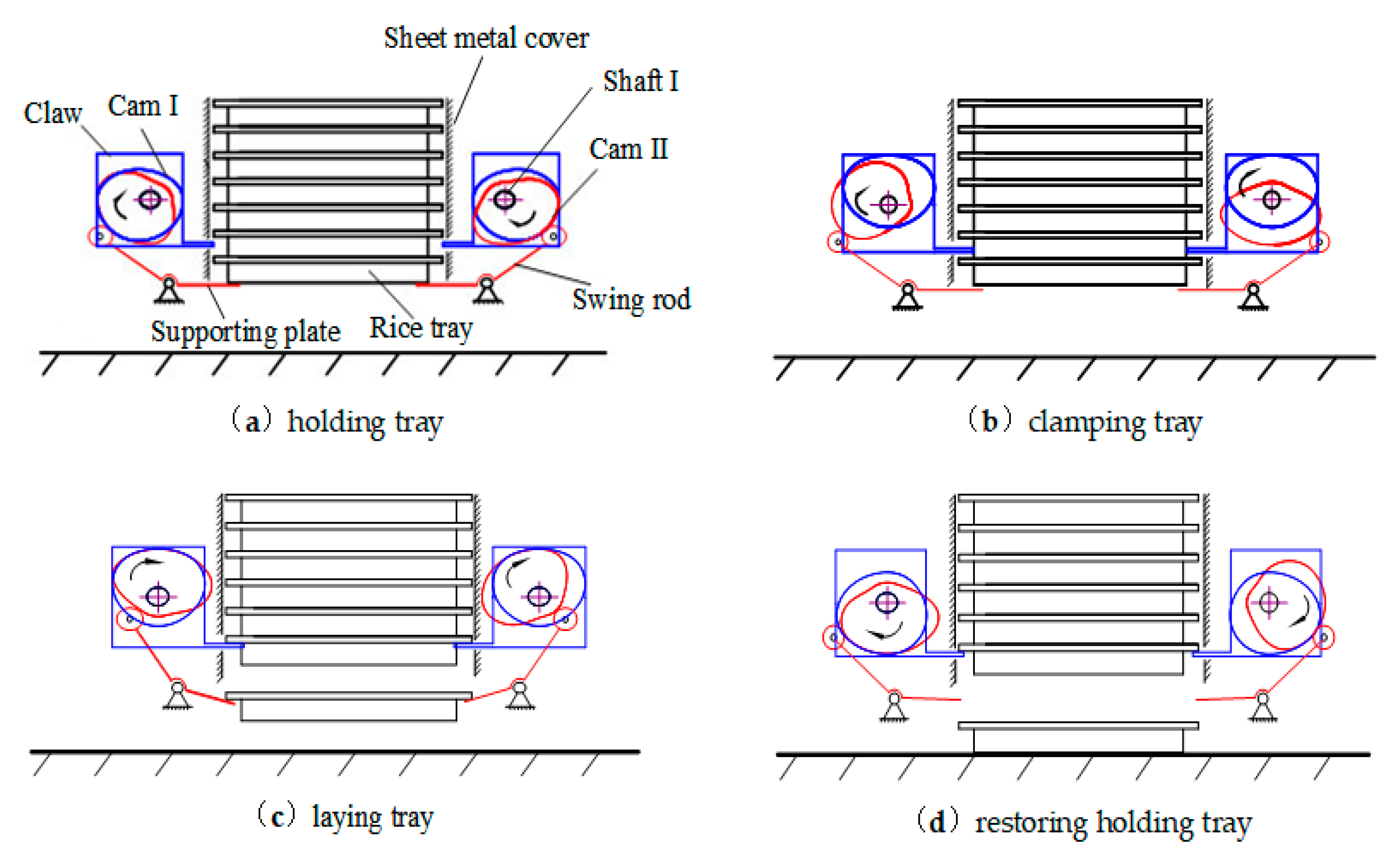
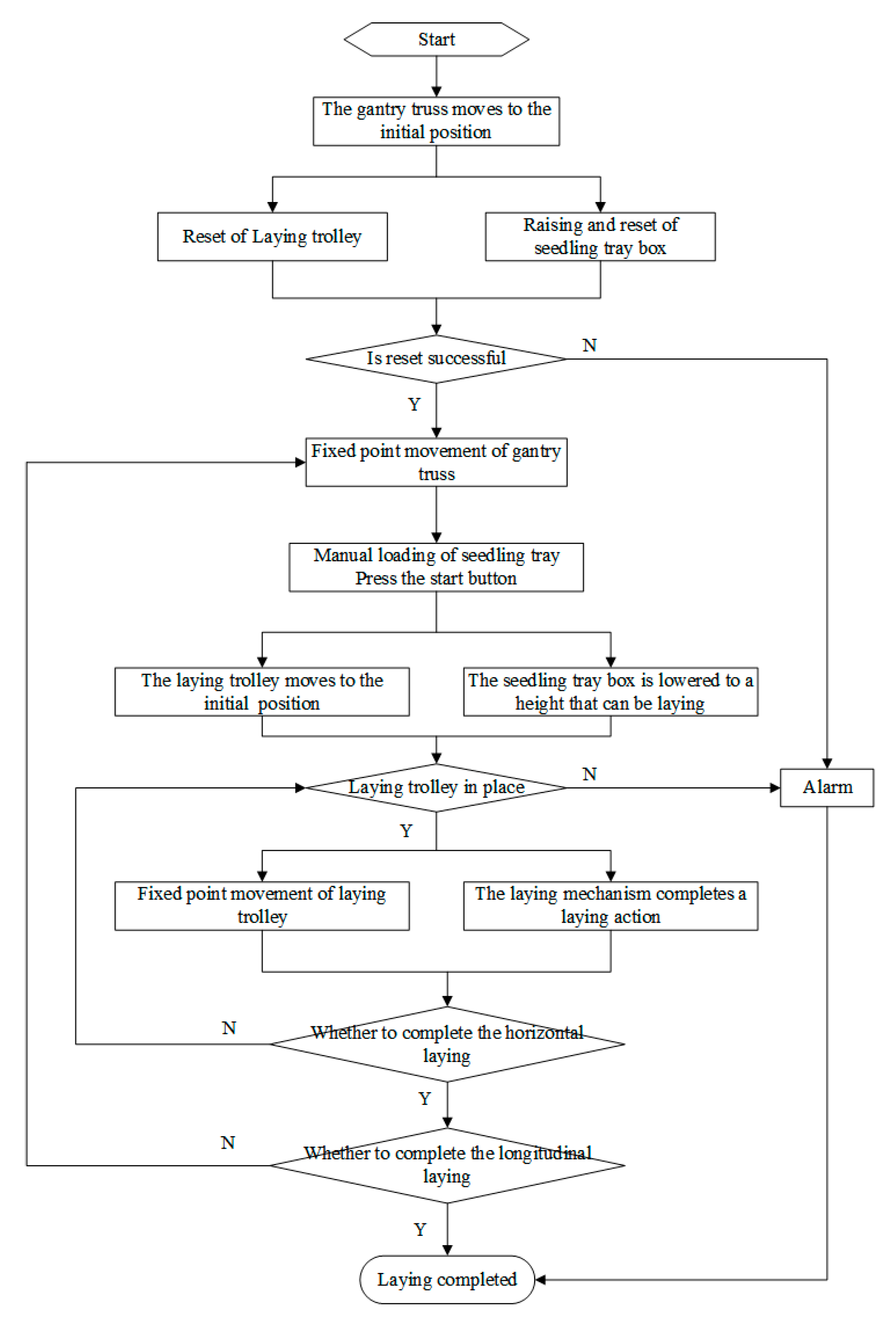
2.2.1. Workflow of Tray Laying System
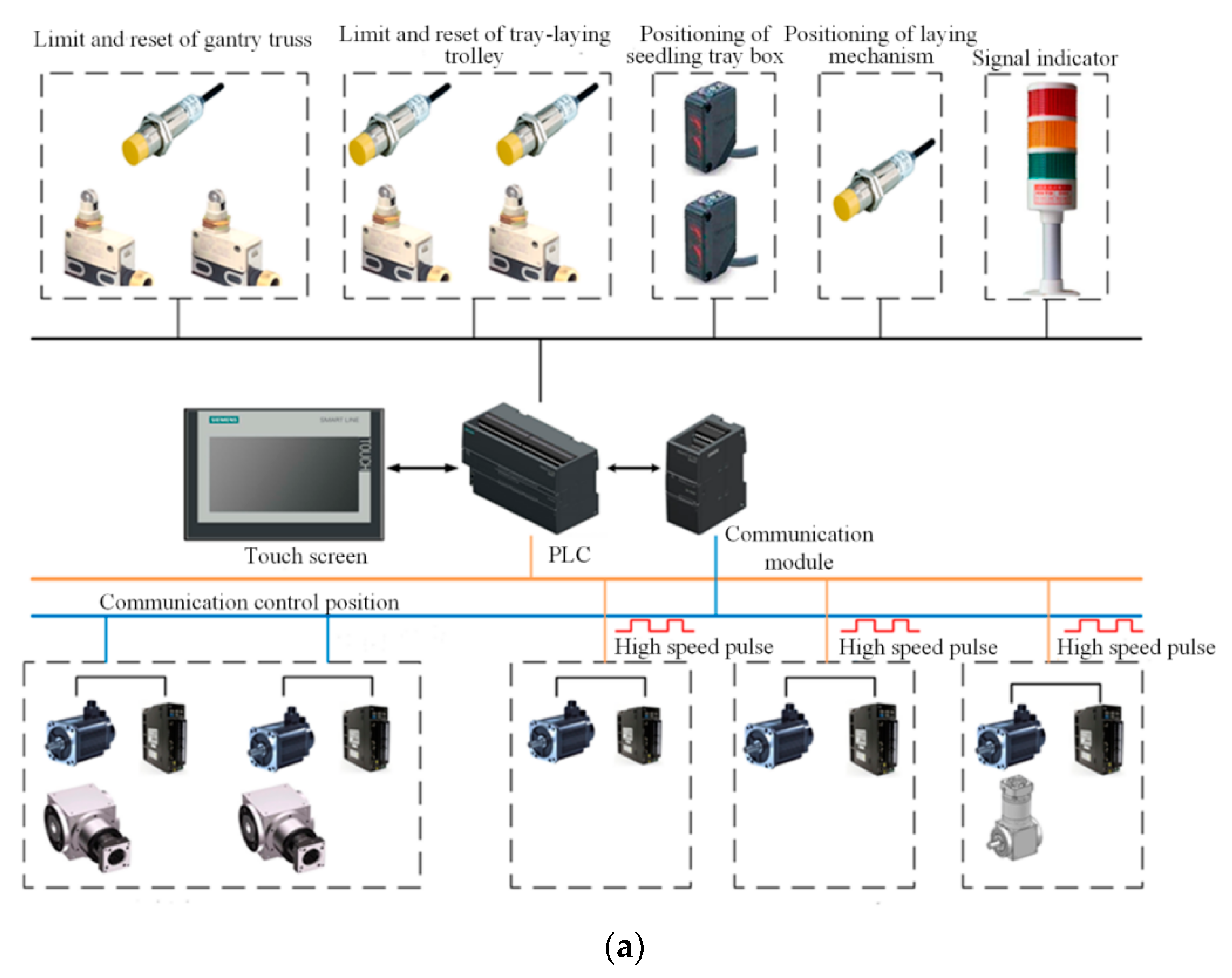
2.2.2. Design of the Control System of Tray Laying System
2.2.3. Control Strategy of Tray Laying System
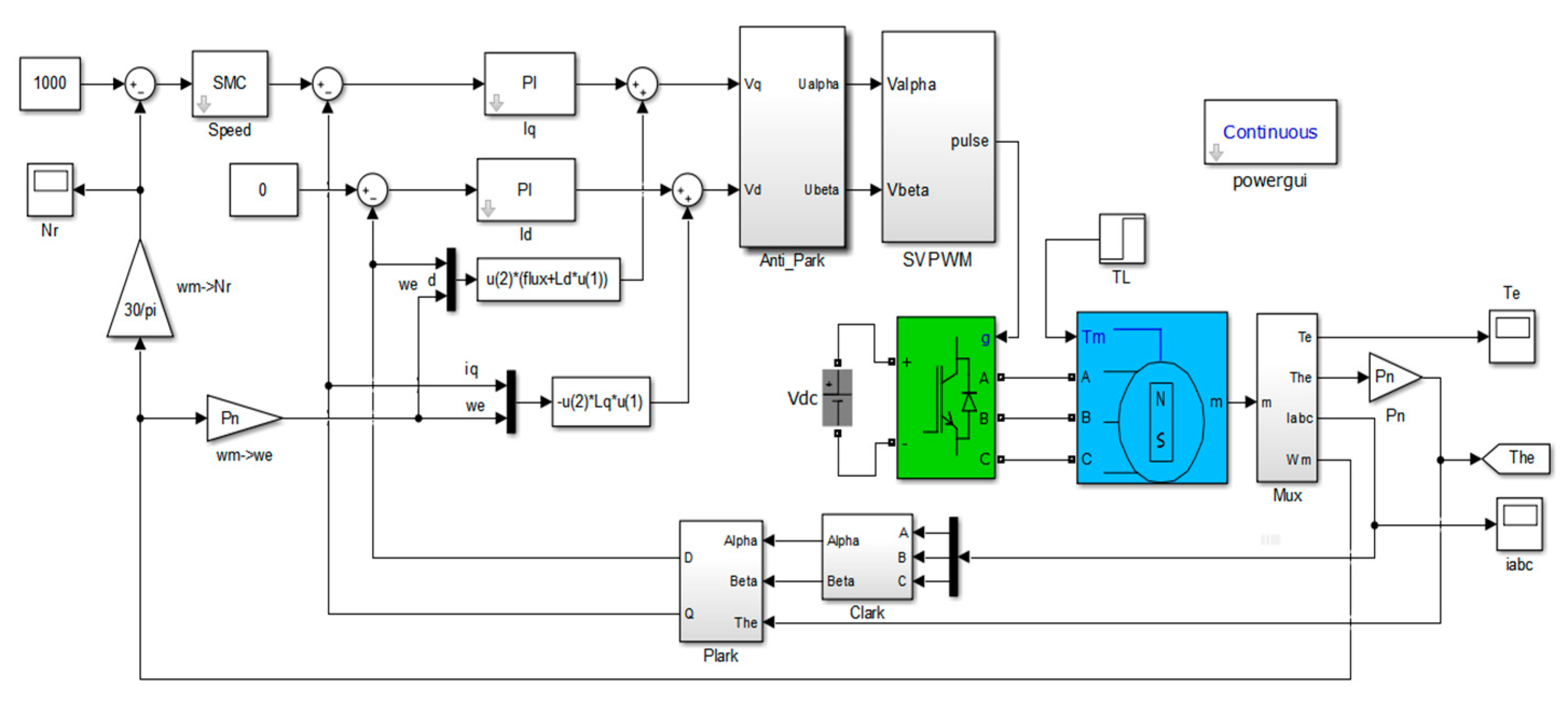
2.2.4. Cooperative Control Method Based on Sliding Mode Speed Control
3. Results and Discussion
4. Conclusions
- (1)
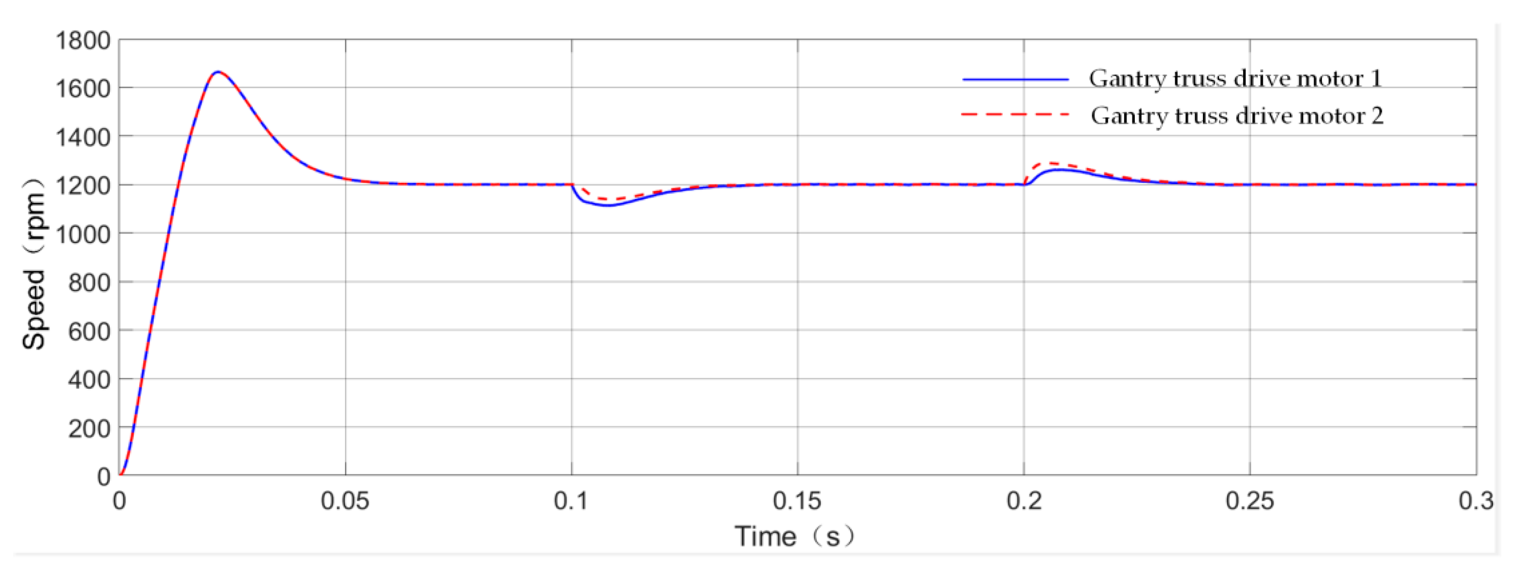
- The agronomic requirements for the horizontal and longitudinal spacing of the seedling tray and efficiency requirements during the tray laying process are to be met. In this paper, a rice tray automatic laying system based on multi motor cooperation is designed, and the multi motor control strategies of key modules are simulated and compared. For the longitudinal movement of the gantry truss, the cross coupling control strategy is adopted to detect and compensate for the synchronous position error of the two driving motors. For the driving motor of the tray laying trolley and the tray laying mechanism, an improved master-slave synchronization control strategy is adopted to improve the efficiency and accuracy of the tray placement.
- (2)
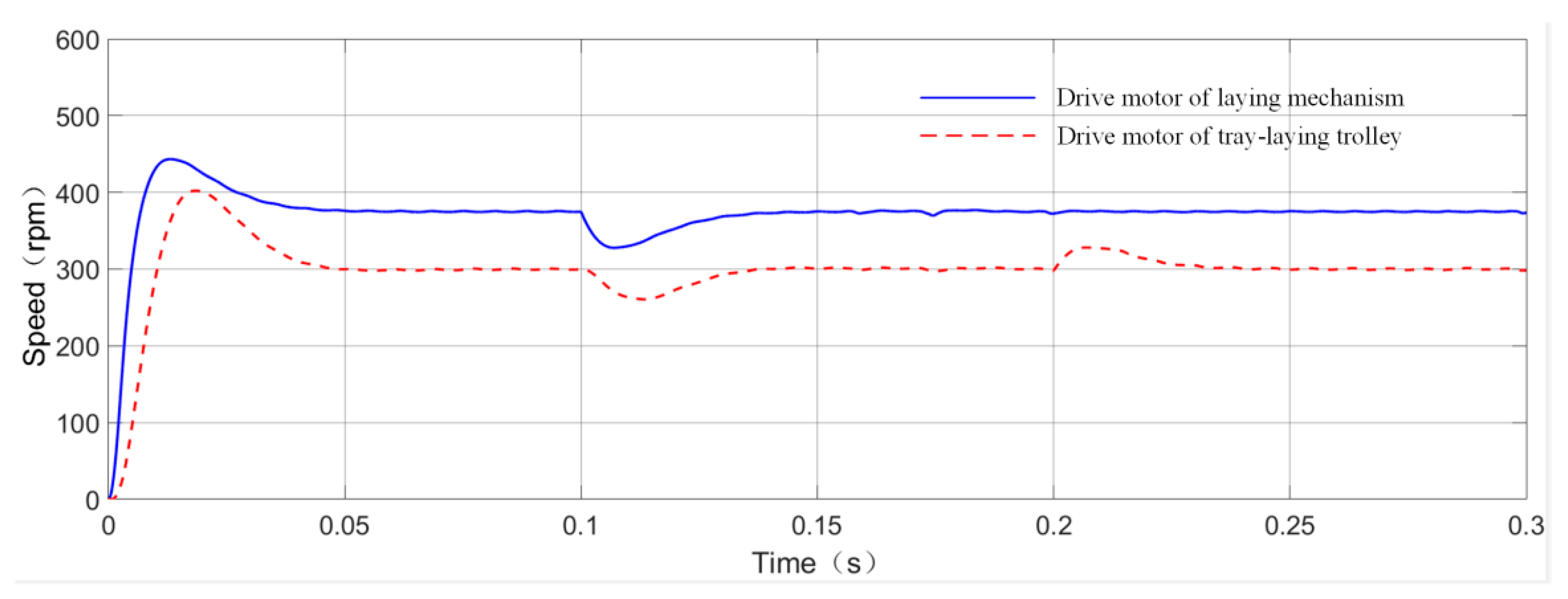
- Through calculations and field tests, the best combination of operating parameters of the system is obtained: The tray laying trolley moves on the gantry truss at the speed of 7.5 cm/s, and the gantry truss moves at a fixed point at a speed of 35 cm/s in the longitudinal direction. When the motor of the tray laying mechanism lays the tray at the speed of 375 rpm at the height of 100 mm from the ground, the system runs most reliably and stably.
- (3)
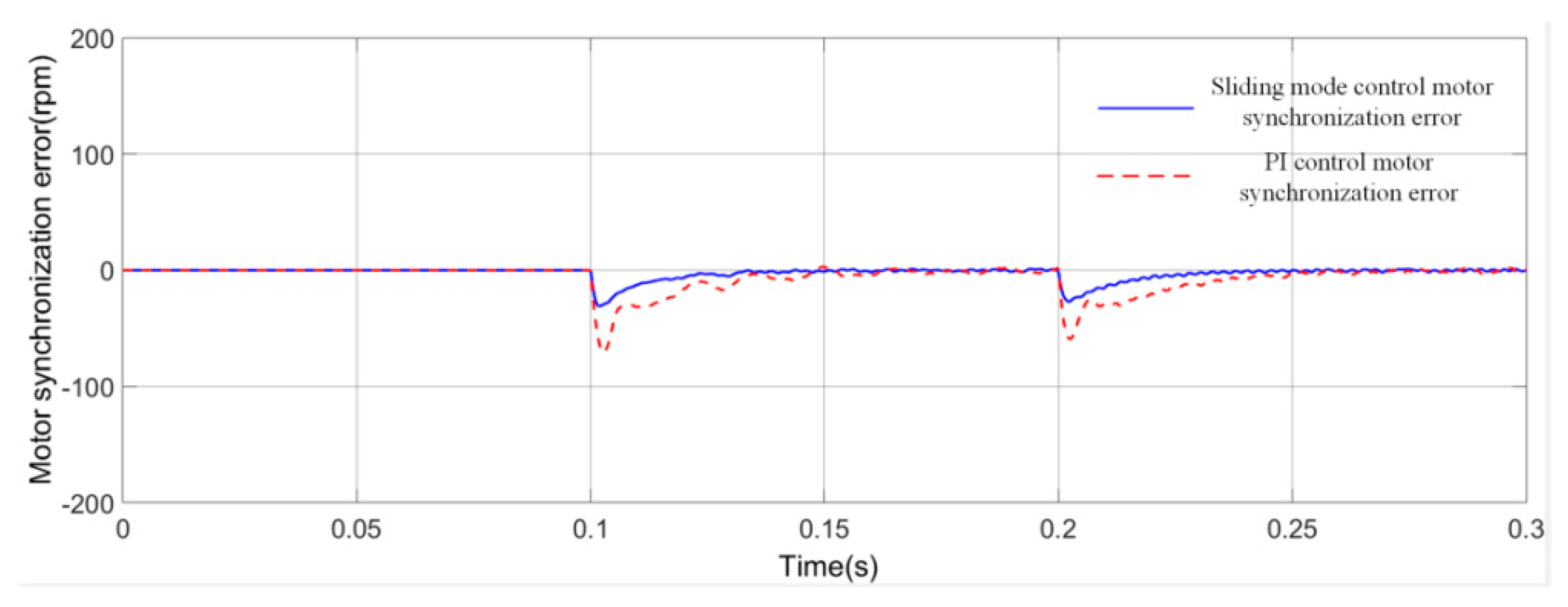
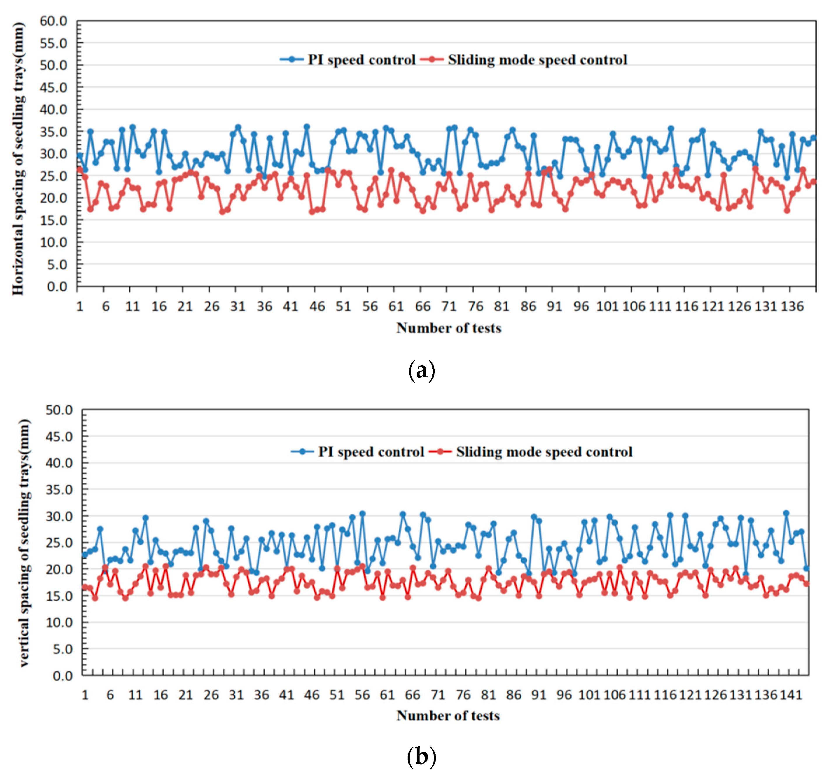
- In order to obtain higher quality and effect of laying, a PMSM sliding mode speed controller is designed, which is applied to the multi motor cooperative control strategy and optimized and simulated. The results of simulation and field tests showed that when the tray laying system was set at the best parameters, the horizontal spacing of tray was kept at 25 ± 5 mm, with longitudinal spacing of 15 ± 5 mm, and the overall offset of the gantry truss was controlled within 20 mm. The qualified rate of laying trays reaches 100%, and the laying efficiency can reach 380 trays/h, which meets the technical requirements of mechanized field laying.
Author Contributions
Funding
Data Availability Statement
Acknowledgments
Conflicts of Interest
References
- Chen, L.; Ma, X.; Qi, L. Present situation and Prospect of automatic tray stacking equipment in rice tray seedling production line. Agric. Mech. Res. 2017, 39, 260–264. [Google Scholar]
- Meerburg, B.G.; Korevaar, H.; Haubenhofer, D.K.; Blom-Zandstra, M.; Van Keulen, H. The changing role of agriculture in Dutch society. J. Agric. Sci. 2009, 147, 511–521. [Google Scholar] [CrossRef]
- Gu, S.; Yang, Y.; Zhang, Y.; Qiao, X. Development status of automated equipment systems for greenhouse vegetable seedlings production in Netherlands and its inspiration for China. Trans. Chin. Soc. Agric. Eng. 2013, 29, 185–194. [Google Scholar]
- Li, Y.; Xu, L.; Xiang, Z. The latest research progress of rice planting mechanization technology in Japan. Trans. Chin. Soc. Agric. Eng. 2005, 11, 190–193. [Google Scholar]
- Yanmar. Rice Seedling Facility Fully Automatic Seedling Box Automatic Supply Device. Available online: www.yanmar.com/jp/agri/products/facilities/rice/raising_seedlings/automated_instrument.html (accessed on 27 December 2015).
- Oh, C.J. Seeding Line for Growing Seedling Tray. South Korea: 1014404370000. Available online: https://analytics.zhihuiya.com/patent-view/abst?limit=100&q=%201014404370000&_type=query&redirect=%2Fsearch%2Finput%23%2Fsimple&patentId=ea79b69f-4c03-45cd-9be0-6ab4948ec610&sort=desc&rows=100&page=1&source_type=search_result. (accessed on 17 September 2014).
- Xie, L. Experiment and Research on the Placing Machine of Rice Seedling Trays; Heilongjiang Bayi Agricultural Reclamation University: Daqing, China, 2015. [Google Scholar]
- Ma, J. Research on Automatic Plate-Wrapping Device for Seedling-Raising Shed; Northeast Agricultural University: Harbin, China, 2014. [Google Scholar]
- Liu, H.; Gu, X.; Xu, C. The design and experiment of the air suction type automatic seedling tray placement machine. J. Agric. Mech. Res. 2018, 40, 134–138. [Google Scholar]
- Zhang, X.; Xie, X.; Yi, J. The design of the automatic placement machine for the joint type vegetable seedling tray after sowing. Trans. Chin. Soc. Agric. Eng. 2018, 34, 27–36. [Google Scholar]
- Chiu, Y.-C.; Wu, G.-J.; Chen, C.-H. Development of a generator-powered self-propelled automatic tray loading/unloading machine for use in rice nurseries. Eng. Agric. Environ. Food 2019, 12, 256–263. [Google Scholar] [CrossRef]
- Wang, J.; Xu, B.; Du, X.; Xu, Z.; Xia, X.; Chen, J. A Field Laying Machine. Chinese: ZL20191007933.6. Available online: http://pss-system.cnipa.gov.cn/sipopublicsearch/patentsearch/showViewList-jumpToView.shtml. (accessed on 4 January 2019).
- Yao, W. Research on Multi Motor Synchronous Control Strategy; Xiangtan University: Xiangtan, China, 2013. [Google Scholar]
- Xin, G. Research on Multi Motor Speed Cooperative Control Strategy; Liaoning University of Technology: Jinzhou, China, 2018. [Google Scholar]
- Ma, C.; Wu, Q.; Hou, Y. Comparative study on multi motor coordinated control strategies. J. Bohai Univ. Nat. Sci. 2019, 2, 186–192. [Google Scholar]
- Liu, X. Multi Axis Synchronous Control of Fixed Length Feeding System; Zhejiang University: Hangzhou, China, 2012. [Google Scholar]
- Dong, S. Position synchronization of multiple motion axes with adaptive coupling control. Automatica 2003, 39, 997–1005. [Google Scholar]
- Hou, W.; Yuan, S. Research on three motor synchronous control method based on Fuzzy PI. Ind. Instrum. Autom. Device 2018, 5, 60–66. [Google Scholar]
- Cao, C.; Wang, B.; Xu, X.; Sun, Y. Research on multi motor bias coupling synchronous control based on neural network. Control Eng. 2013, 3, 415–418. [Google Scholar]
- Zang, J. Research on Piecewise Sliding Mode Control Method of Permanent Magnet Synchronous Motor Servo System; Harbin University of Technology: Harbin, China, 2019. [Google Scholar]
- Liu, J. Matlab Simulation of Sliding Mode Variable Structure Control; Tsinghua University Press: Beijing, China, 2005. [Google Scholar]


| Comparison Index | Modular Splicing | Hand Push/Self-Propelled | Gantry Rail Type |
|---|---|---|---|
| Innovation | Weak | General | Strong |
| Structure | Simple | Moderate | Moderate |
| Cost | Low | Moderate | Moderate |
| Versatility | Strong, suitable for multi-standard seedling trays | Poor, suitable for seedling trays of specific specifications | Generally, suitable for mainstream seedling trays |
| Automation | Low, need farmer intervention | Moderate, need to manually load a single seedling tray | High, can load 8–10 stacked seedling trays at a time |
| Operating | Difficult, need to adjust the coordination between the various modules | Generally, farmers are required to follow the tray laying device in the seedling field throughout the entire process | Easy, farmers only need to load seedling trays on one side and press the start button |
| Effectiveness | Low | Moderate | High |
| Control method | Simple, only need switch and single motor control | Moderate, requiring simple mechanical combination control | Complex, requiring coordinated control of multiple motors |
| Material Name | Yield Point (MPa) | Tensile Strength (MPa) | Density (g cm−3) | Elastic Modulus (GPa) | Poisson’s Ratio |
|---|---|---|---|---|---|
| Q235 | 235 | 375 | 7.85 | 7.85 | 0.28 |
| Payload Name | Loading Method | Load Value |
|---|---|---|
| Gantry truss | Automatic generated | / |
| Tray laying Trolley | Applied surface load | 110 kg |
| Rice seedling tray | Applied surface load | 20 kg |
| Judgment Factor | Parallel Closed Loop Control | Cross-Coupling Control | Master-Slave Servo Control | |||
|---|---|---|---|---|---|---|
| Maximum | Minimum | Maximum | Minimum | Maximum | Minimum | |
| Horizontal spacing of seedling trays (mm) | 38.4 | 27.5 | 36.1 | 26.2 | 37.2 | 26.9 |
| Longitudinal spacing of seedling trays (mm) | 26.7 | 17.2 | 24.8 | 15.7 | 25.4 | 16.1 |
| The angle between the gantry truss and the track (degree) | 88.7 | 82.5 | 89.1 | 85.4 | 88.9 | 84.4 |
| Truss offset (mm) | 69.8 | 2.2 | 26.3 | 1.1 | 38.9 | 1.6 |
| Whether the motor can be kept in coordination | No | Yes | Only the slave motor can follow the master motor | |||
| Control strategy complexity | Low | Complicated | Commonly | |||
| Key Factors of Laying | PI Speed Control | Sliding Mode Speed Control | ||||||
|---|---|---|---|---|---|---|---|---|
| Maximum | Minimum | Average | Variance | Maximum | Minimum | Average | Variance | |
| Horizontal spacing of tray (mm) | 36.0 | 24.5 | 30.2 | 11.7 | 26.5 | 16.8 | 21.7 | 7.9 |
| Longitudinal spacing of tray (mm) | 19.1 | 30.4 | 24.5 | 10.1 | 20.5 | 14.4 | 17.5 | 3.1 |
| Angle between gantry truss and track (degree) | 88.2 | 85.2 | 86.4 | 0.6 | 89.2 | 87.1 | 88.2 | 0.3 |
| Truss offset (mm) | 28.7 | 4.1 | 15.7 | 37.9 | 11.3 | 1.0 | 4.6 | 8.7 |
| Number of stacked trays | 3 | 0 | ||||||
| Unqualified laying | 6 | 0 | ||||||
| Efficiency of laying trays | 280 trays/h | 380 trays/h | ||||||
| Success rate of laying | 96.7% | 100% | ||||||
Publisher’s Note: MDPI stays neutral with regard to jurisdictional claims in published maps and institutional affiliations. |
© 2021 by the authors. Licensee MDPI, Basel, Switzerland. This article is an open access article distributed under the terms and conditions of the Creative Commons Attribution (CC BY) license (https://creativecommons.org/licenses/by/4.0/).
Share and Cite
Zhou, Q.; Xia, X.; Wang, J.; Zhou, Y.; Chen, J. Design and Experiment of the Automatic Laying System for Rice Seedling Tray. Agriculture 2021, 11, 679. https://doi.org/10.3390/agriculture11070679
Zhou Q, Xia X, Wang J, Zhou Y, Chen J. Design and Experiment of the Automatic Laying System for Rice Seedling Tray. Agriculture. 2021; 11(7):679. https://doi.org/10.3390/agriculture11070679
Chicago/Turabian StyleZhou, Qiaojun, Xudong Xia, Jian Wang, Yun Zhou, and Jianneng Chen. 2021. "Design and Experiment of the Automatic Laying System for Rice Seedling Tray" Agriculture 11, no. 7: 679. https://doi.org/10.3390/agriculture11070679
APA StyleZhou, Q., Xia, X., Wang, J., Zhou, Y., & Chen, J. (2021). Design and Experiment of the Automatic Laying System for Rice Seedling Tray. Agriculture, 11(7), 679. https://doi.org/10.3390/agriculture11070679