Article

A Design of an Unmanned Electric Tractor Platform

Department of Vehicle Engineering, National Pingtung University of Science and Technology, Pingtung 912, Taiwan
*
Author to whom correspondence should be addressed.
Agriculture 2022, 12(1), 112; https://doi.org/10.3390/agriculture12010112
Submission received: 24 November 2021 / Revised: 10 January 2022 / Accepted: 10 January 2022 / Published: 14 January 2022
(This article belongs to the Special Issue Design and Application of Agricultural Equipment in Tillage System)

Abstract

:
The tractor is a vehicle often used in agriculture. It is mainly used to tow other unpowered agricultural machinery for farming, harvesting, and seeding. They consume a lot of fuel with emissions that often contain a large amount of toxic gases, which seriously jeopardize human health and the ecological environment. Therefore, the electrical tractor is bound to become a future trend. The objective of this study is to design and implement a lightweight, energy-saving, and less polluting electric tractor, which meets the requirements of existing smallholder farmers, equipped with unmanned technology and multi-functions to assist labor and to provide the potential for unmanned operation. We reduced the weight of the tractor body structure to 101 kg, and the bending rigidity and torsional rigidity reached 11,579 N/mm and 4923 Nm/deg, respectively. Two 7.5 kW induction motors driven by lithium batteries were applied, which allows at least 3.5 h of working time.

1. Introduction

In recent years, with the rapid development of industrialization, agricultural machinery has gradually replaced traditional labor-intensive farming methods, improved work efficiency, and reduced manpower requirements. This is a major change in agricultural history. Today, agricultural machinery has developed into different forms, for example, agricultural machinery for arable land, for planting and fertilizing, for field management, etc. However, the wide usage of agricultural machinery increases the use of internal combustion engine vehicles, causing air pollution, environmental damage, and rapid consumption of land resources. According to statistics, global natural gas, oil, and coal resources can be supplied for another 30 years, 55 years, and 152 years, respectively [1]. Global environmental awareness is gradually rising. In order to reduce the harm to the environment, many countries have begun to promote electric vehicle-related industries vigorously, and have achieved good results in batteries, hybrid vehicles, and electric vehicles.
The tractor is a vehicle often used in agriculture. It is mainly used to tow other unpowered agricultural machinery for farming, harvesting, and seeding. For sedans, the key performance criteria are speed, loading force, and traction, but for tractors, high-speed performance and strength for traction are not important. The tractor needs to pull agricultural machinery and implement farmland farming. The tractor can have different operation modes depending on the agricultural tools with which it is equipped. If a Western plow, harrow, or raking machine, etc., is mounted behind the tractor, a plowing operation can be carried out. If the tractor is equipped with a rotary plow, the power transmission device of the tractor can be used for rotary tillage. Adding a flat soil board or a rice transplanter to the tractor can achieve soil leveling or planting operations, so the tractor is essential in agriculture. The agricultural tractors used in Taiwan are less driven by motors. However, as a trend for small-scale farmers, greenhouse planting emphasizes the development of technological agriculture and is environmentally controlled. The development of agricultural machinery needs to fulfill users’ requirements and provide a safe and environmental-friendly configuration to reduce labor demand and improve work comfort for better agricultural production.
Electric tractors have been studied since the 19th century. The first electric tractor appeared in the USA [2,3], and subsequent developments were mainly powered by batteries. A 36.8 kW electric tractor manufactured by German Siemens in 1912 was the first electric tractor [4], which was mainly used for rotary tillage operations. The German company, Bungartz, developed an electric tractor called Töpfer in 1945. It was equipped with a gearbox and had a speed control function. Its key characteristic was to move both forward and backward without turning [5]. Later, General Electric (USA) introduced the Elec-Trak series of electric tractors. This electric tractor used lead-acid batteries to drive a permanent magnet brushless motor. The motor power was between 5.9 kW and 11 kW. In addition, the tractor was equipped with a rotary converter, which could tow other agricultural implements [6]. Since the 1990s, the control and battery technology have developed rapidly, and the performance of electric tractors has gradually improved, and there is more research devoted to the development of electric tractors and their electromechanical related design [7,8,9].
Furthermore, many articles are devoted to studying the performance and stability of tractors [10,11,12,13]. Improving the effectiveness of tillage is closely related to the characteristics of soil, and it is one of the areas that cannot be ignored [14,15,16]. There is a lot of research on autonomous driving [17,18,19,20,21], but there is very little on intelligent electric vehicles for unmanned driving in agriculture. We will enable these devices for autonomous driving on the field either to reach fixed points or to follow planned routes in farming.

2. Materials and Methods

The vehicle design was divided into four parts: the vehicle body design, which is lightweight and contains safety considerations; the power and vehicle control, which provides vehicle power and covers a series of system integration and unmanned controls; the mechanism design, which improves the mechanical functions and analyzes the state of the vehicle driving; and the field tests and the implementation of the whole vehicle. The divisions are shown in Figure 1.
The tractor type and the related load affect the power consumption and the design of the vehicle. For a small electric tractor, the size, mass, and motor power are smaller than those of a high-load tractor. The designed tractor will be mainly used for rotary tillage and plowing operations, so the resistances are calculated based on the rotary tillage operation. Since the designed electric tractor is mainly operated in greenhouses, which have rather flat terrain, the slope resistance and air resistance of the tractor are not taken into consideration. The configuration and parameters are shown in Figure 2 and Table 1.
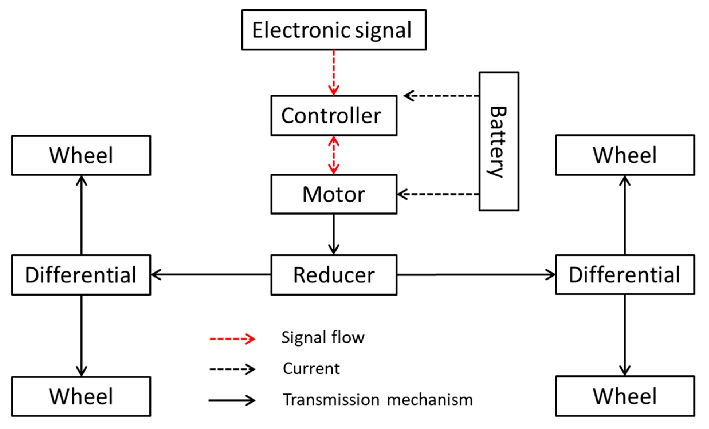
In addition, the tractors require a wide range of force changes, especially when working under heavy loads, which requires larger torque output. Therefore, the reducer must be used to decelerate and increase the torque to respond to different conditions. The drive motor can be adjusted and is equipped forward and reverse rotation to achieve reverse gear requirements. When transporting in the field, it can be switched to a high gear to increase the speed. In addition, when working in the field, the wheels may have insufficient grip due to the road or terrain, so a four-wheel drive system is required. Based on the above analysis, the power system configuration of the electric tractor in this study is shown in Figure 3, which is equipped with a motor, a reducer, a differential, and a controller.

3. Body Design

The body of the small tractor is equipped with an on-board motor and a battery system. The tractor must meet the requirements of rigidity, safety, strength, and fatigue durability. The analysis process first established the prototype of the car body, then used TOSCA topology optimization analysis for lightweight analysis and ABAQUS finite element analysis for strength check, and finally used fe-safe fatigue life analysis to calculate the fatigue life of the vehicle body on different road grades.

3.1. Lightweight Design and Analysis of Car Body

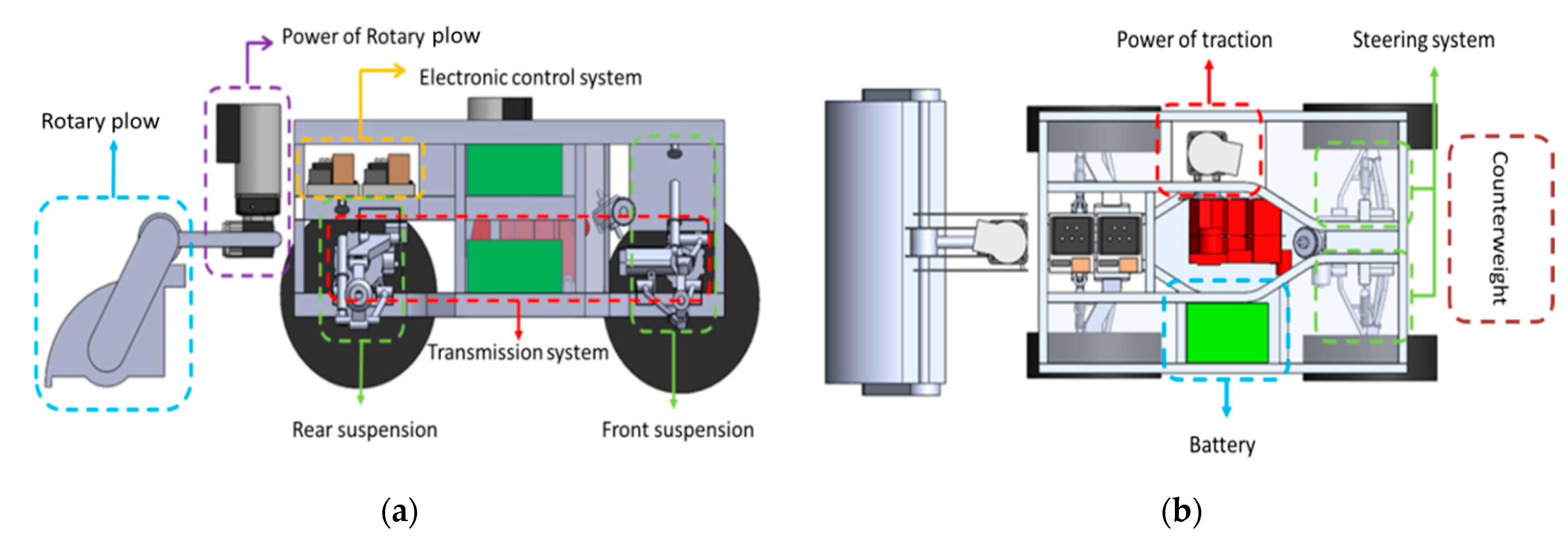
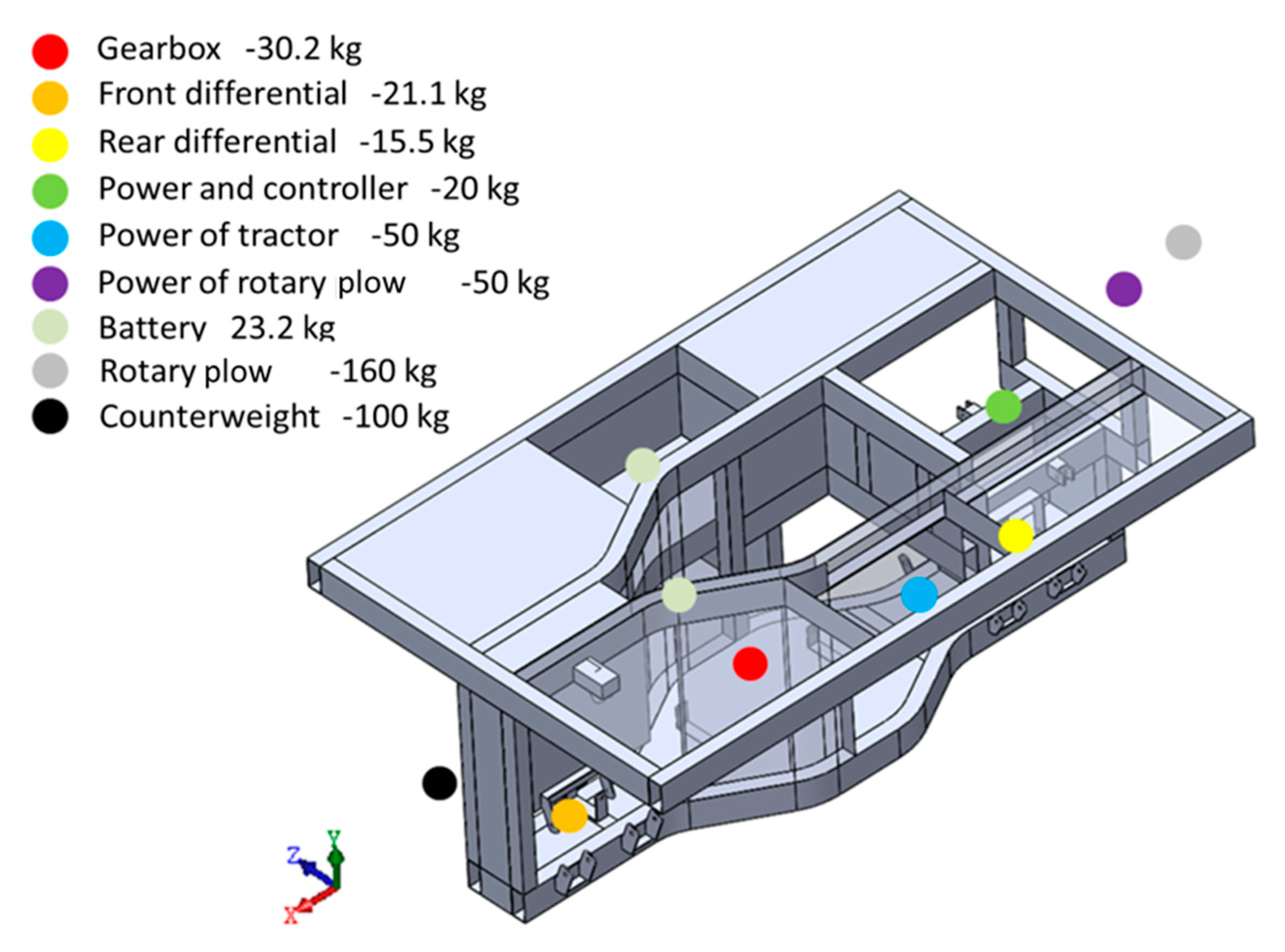
During the space planning, the load position of each system on the vehicle was considered, such as the vehicle power system, steering system, suspension system, transmission system, electronic control system, battery, counterweight, rotary plow power system and slewing plow, etc., as shown in Figure 4. The required bearing weight of the vehicle included the vehicle power system, steering system, transmission system, electronic control system, battery, counterweight, rotary plow power system, rotary plow, and other weights. The target weight of the vehicle body was 120 kg. The total weight was estimated to be 650 kg. In order to reduce manufacturing costs, a commercially available transmission system and suspension system with a wheelbase of 1297 mm were selected. The power system was placed on the left side of the vehicle body for the power transmission. To balance the center of gravity, two lithium batteries were placed on the right side of the vehicle body to reduce the possibility of overturns. The power system was planned to be 350 mm in length, 338 mm in width, and 285 mm in height, and the battery is 338 mm in width, and 660 mm in height, and 480 mm in length. During transportation, the rotary plow at the rear of the vehicle body will be raised and the center of gravity will be moved backwards. Therefore, a counterweight of about 100 kg was installed in the front of the vehicle body to maintain balance. Based on the above-mentioned configuration, the preliminary frame size was 1720 mm in length, 1100 mm in width, and 660 mm in height.
In order to complete the required setting under the existing conditions, the vehicle types similar to this study were evaluated, space planning of the whole vehicle was carried out, including transmission, suspension type, wheelbase, type and quantity of battery, etc. The prototype of an electric tractor was established, and a topology optimization analysis of this structure was conducted. According to the topological optimization analysis, an overall structural material distribution was obtained for reference, and a preliminary conceptual design of an electric tractor was proposed.
It was necessary to confirm whether the preliminary conceptual design met the design goals. Once the design goals were met, manufacturing feasibility was considered for welding deformation and component interferences. The body of the preliminary conceptual design was modified to obtain the final conceptual design. The completed vehicle body was imported into ABAQUS to create a finite element model and to conduct rigidity and strength analysis to confirm whether the rigidity and strength of the vehicle body met the design goals. If the design goals were not met, the structure was modified. Once the final vehicle body was obtained, the body was imported into the fe-safe for fatigue analysis. The fatigue life theory and rain flow cycle counting method were used to calculate the fatigue life. Figure 5 shows the analysis process of the lightweight design of the small electric tractor for this study.
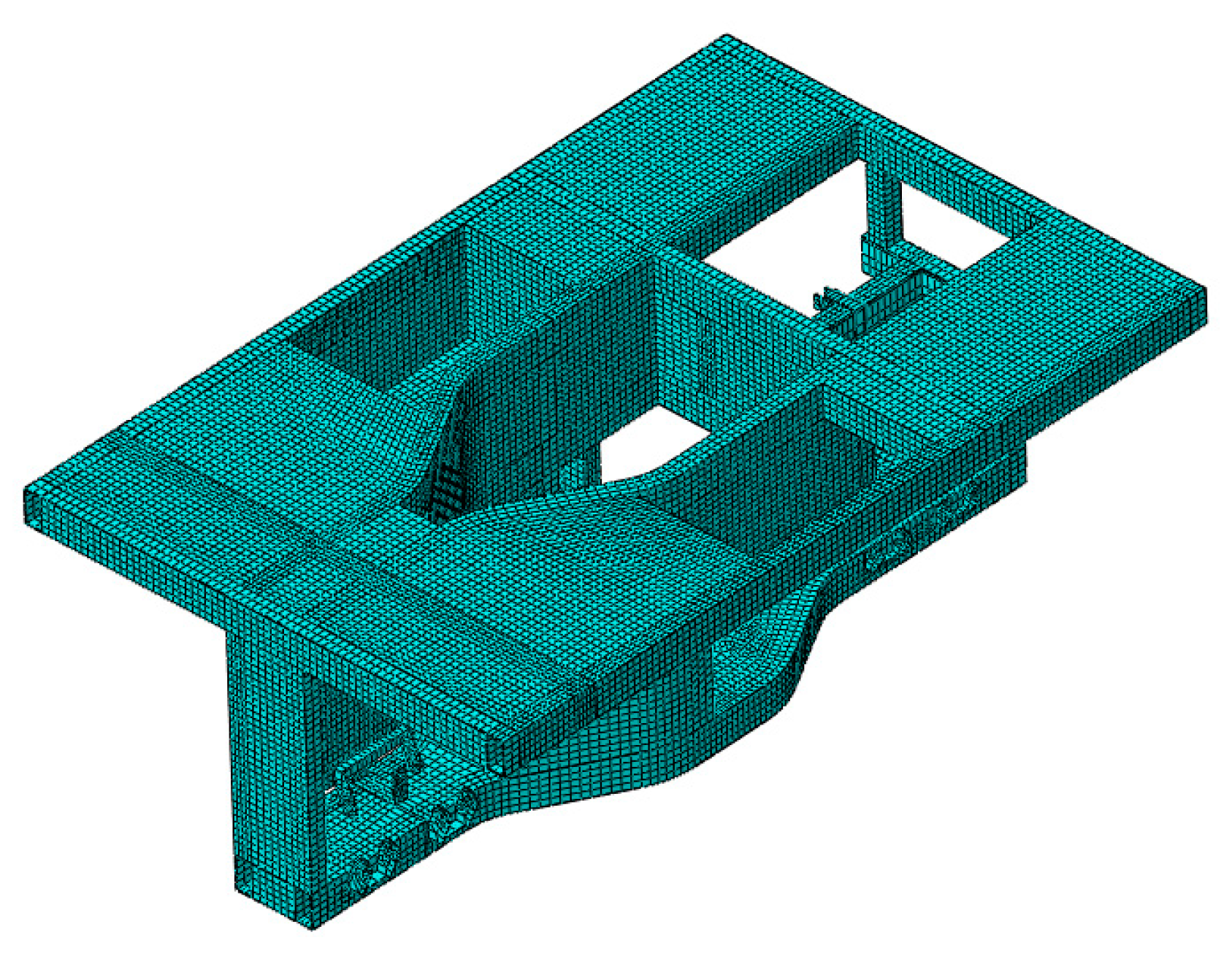
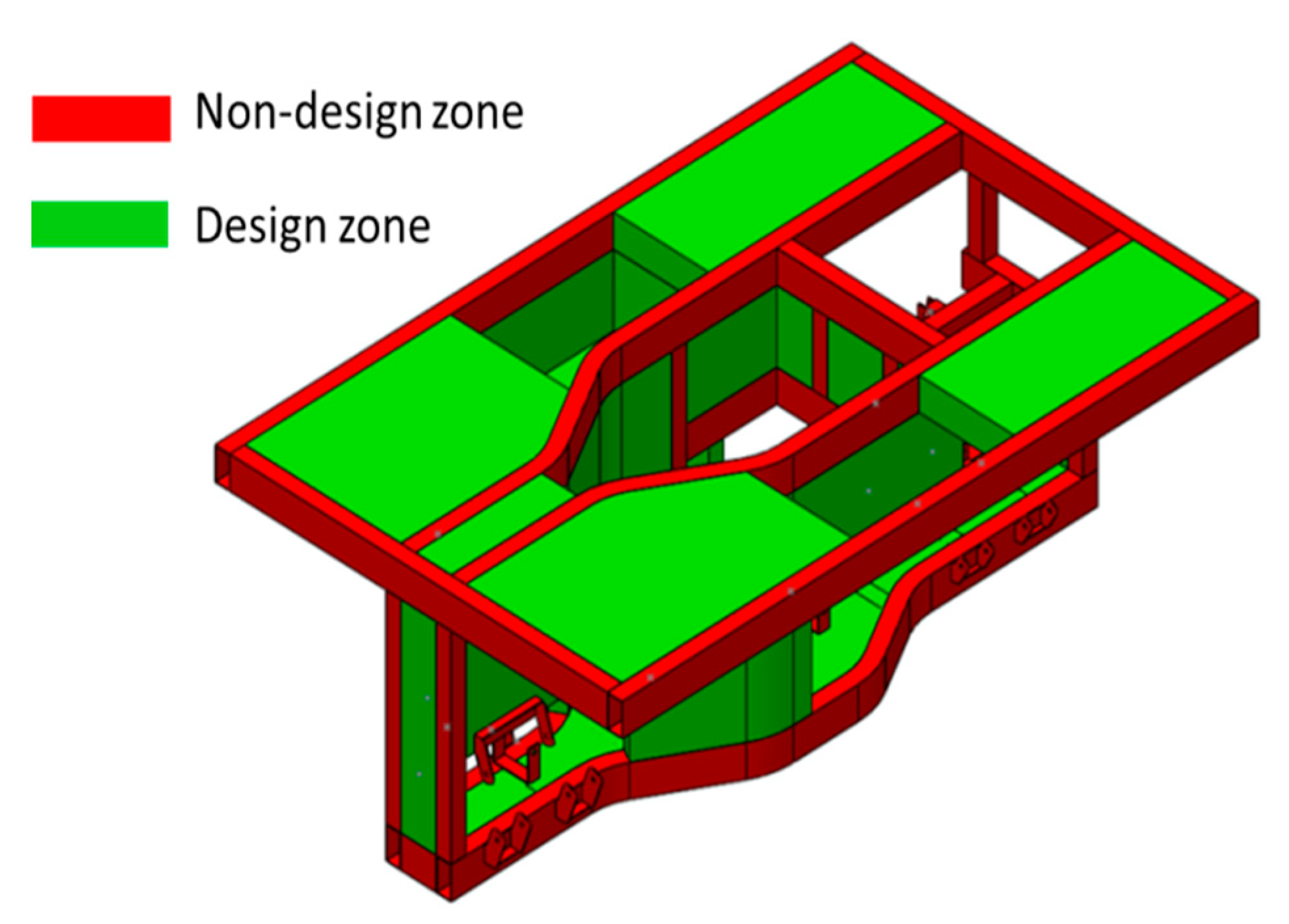
First, the prototype of the vehicle body that was planned during the space layout was imported into ABAQUS to build a finite element model, as shown in Figure 6. Then the area to be made lightweight in the TOSCA topology optimization analysis software was defined as the design zone, shown as the green area in Figure 7. Considering the compatibility of the suspension system and the transmission system, the space and hardpoints were reserved for the shock absorbers, upper and lower control arms, power system, steering system, and transmission system, etc. The outer frame of the vehicle was defined as the non-design zone, the red area shown in Figure 7. Next, the material parameters of the vehicle body in the design area and the non-design area were defined. This study mainly used high-strength steel SPFH 590 and STKM 11A for materials. The properties of the materials are shown in Table 2. The topology optimization analysis, which were load condition analyses, including bending, torsion, and full load braking, was mainly static. The load conditions of these three types were all the same, and the weight of all the load-bearing objects was applied to the vehicle body as shown in Figure 8. Then the boundary conditions were set separately according to the bending strength analysis, torsion strength analysis, and load braking strength analysis.

3.2. Fatigue Life Analysis

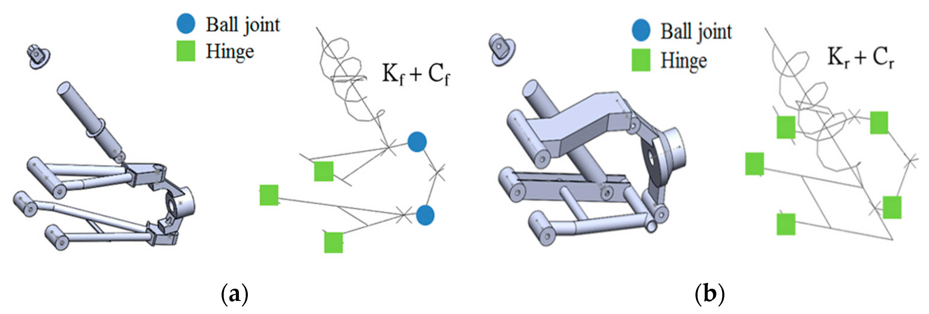
In order to confirm the fatigue life of the frame, the geometric model of the final conceptual design of the vehicle body was imported into the ABAQUS to establish the finite element model. In the fatigue life analysis of the vehicle body, the suspension system did not undergo fatigue life analysis; the suspension model was described as simplified beam elements. In Figure 9, Kf is the stiffness value of the front shock absorber spring, Kr is the stiffness value of the rear shock absorber spring, Cf is the damping value of the front shock absorber, and Cr is the damping value of the rear shock absorber. The simplified suspension model was simulated by a three-dimensional two-node beam element and defined as a rigid body. In the fatigue life analysis, a three-dimensional dynamic elastoplastic finite element model was used, and the element type was eight-node hexahedral.
A.
Material parameters
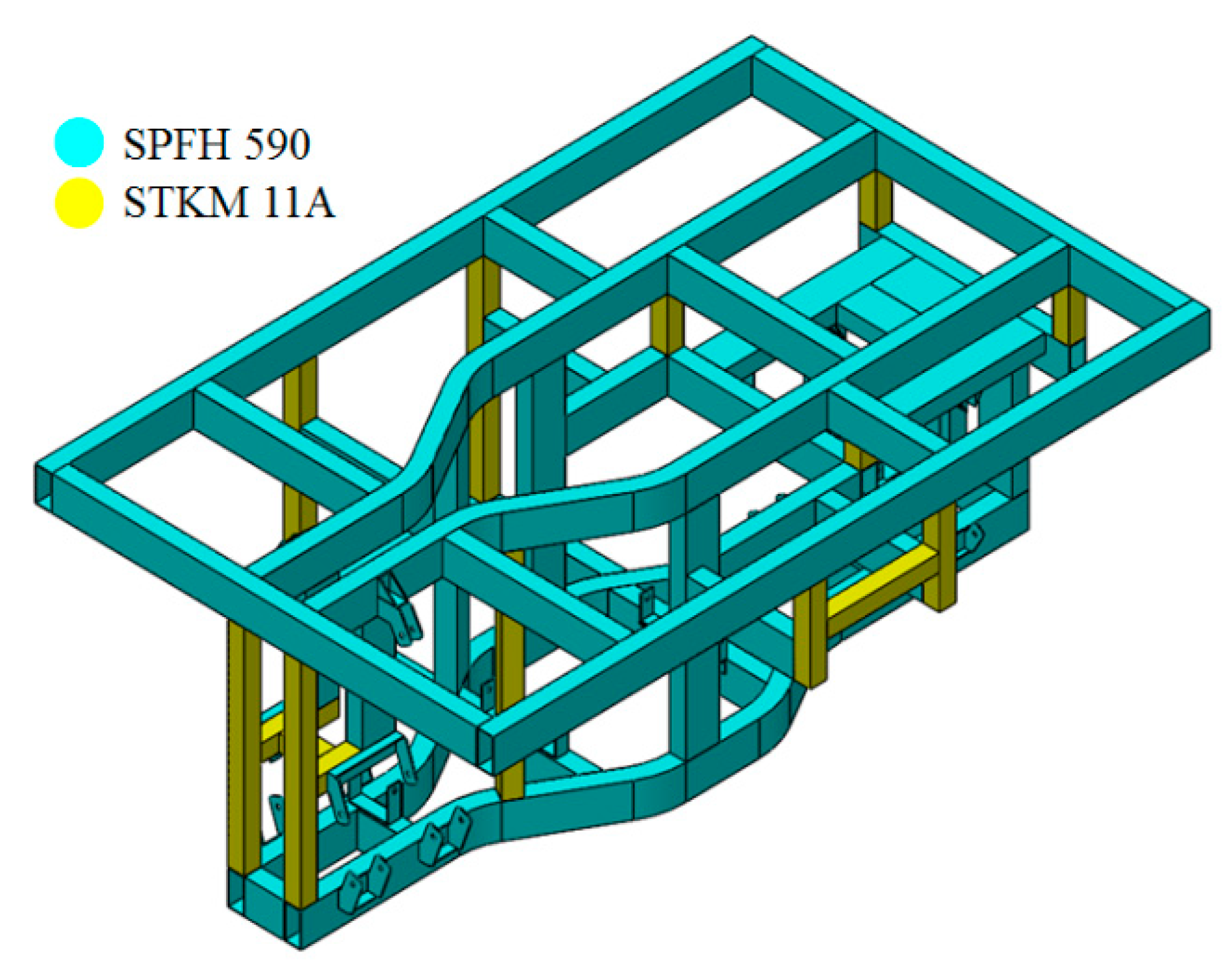
When the vehicle is running, the structure of each part bears different stresses from different load. Since the tractor often works in the field, and the working environment is relatively harsh compared with ordinary vehicles, SPFH 590 high-strength steel was used as the main material of the vehicle structure. Due to the small load between the upper and lower layers of the vehicle, steel STKM 11A was used between the 2 layers. The suspension hardpoints and the reinforced plate were used to meet the assembly requirements with SPFH 590, which were cut by laser and formed by bending. Other parts of the vehicle body used different materials, as shown in Figure 10.
B.
Loading conditions
In the fatigue life analysis, different load conditions were applied on the vehicle body based on the working conditions and operations. For example, the rotary plow was placed on the ground and counted as unsprung mass. There was no load from the rotary plow in the analysis. In addition, traction resistance will be generated during rotary tillage operations, so resistance was applied to the rear of the vehicle body.
C.
Boundary conditions
The boundary conditions of the fatigue life analysis are shown in Figure 11. In the figure, Kf and Kr are the stiffness of the front and rear suspension springs, respectively, which both equaled 27.5 N/mm. Cf and Cr are the damping values of the front and rear suspension shock absorbers whose values were set as 0.96 N.s/mm and 2.16 N.s/mm, respectively. During analysis, road signals of different levels in y direction were applied to the wheel center. Table 3 lists the parameters of the spring stiffness and shock absorber damping coefficient of the front and rear suspension systems during the fatigue life analysis.
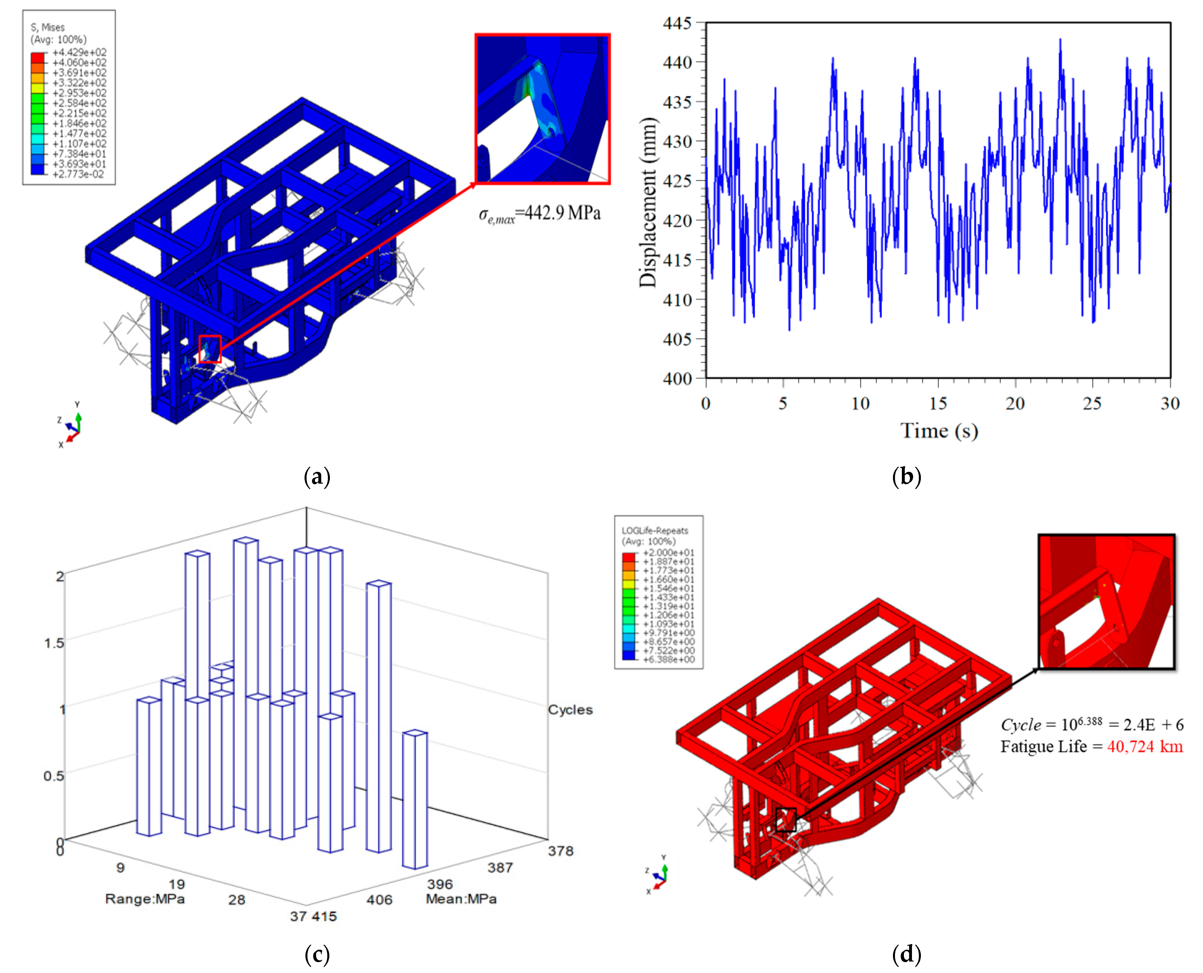
Fe-safe was used to predict fatigue life. It uses the rain flow method to count the number of stress amplitude occurrences and the average stress. Here, the rotary tillage with a larger load was selected for illustration. When the vehicle body is used for rotary tillage, Figure 12a and Figure 13a show the von-Mises stress distribution diagrams obtained from the simulation of the vehicle body driving on the C- and D-level road surfaces at a speed of 2 km/h. It is observed that both σe,max occurred at the hardpoint of the upper control arm of the left front suspension. The stress histories of this location, as shown in Figure 12b and Figure 13b, were respectively imported into the fe-safe software for calculation. The rain flow counting method was used to calculate the stress history of the C-and D-level road surface. The stress amplitude σa and the number of occurrences of average stress σm are shown in Figure 12c and Figure 13c. The fatigue life of the vehicle body obtained from the fe-safe simulation was N = 2.4 × 10⁶ and N = 6.7 × 10⁵, which also means the vehicle can travel 40,724 and 11,190 km, respectively, as shown in Figure 12d and Figure 13d.

4. Power and System Integration

Due to different operating conditions and load distributions of the tractor, there are also different requirements for the performance of the tractor. The power system of the electric tractor must be designed according to the load distribution in different operating conditions. It was calculated according to the requirements of the vehicle under various operating conditions, with a suitable drive motor and reducer.

4.1. Force Estimate and Power System Planning

The resistance of the tractor is related to the selection of the specifications of the power system, so the total resistance of the tractor during transportation operations and rotary tillage operations can be calculated. In addition, the electric tractor uses two drive motors (induction motors) for rotary tillage operations, one for driving the tractor, and one for driving the rotary plow operation, etc. When the tractor is transporting, the motor driving the rotary plow will not work. At this time, the driving force of the whole vehicle is relatively small.

4.1.1. Force Estimate

In the transportation operation, the required driving force can be obtained [22]:
Fq1 = f G = 0.12 × 6474.6 = 776.95 N
where f = 0.12 is the rolling resistance coefficient, and G = 6474.6 N is the vehicle weight.
Before the driving force Fq2 required for the rotary tillage operation can be calculated, it is necessary to know the rotary tillage speed ratio λ and the soil cutting pitch S. After calculating these two values, the rotary tillage specific resistance Kλ and the soil resistance FL can be obtained, and then the rotary tillage can be calculated. The driving force Fq2 is required for the operation. The rotary tillage speed ratio λ can be obtained by formula (2):
λ = 2 π r n r 60,000 v m = 2 π × 205 × 236 60,000 × 0.55 = 9.2
where r = 205 mm is the turning radius of the scimitar, n r = 236 r/min is the rotary knife shaft speed, and vm = 0.55 m/s is the tractor speed. After calculating the rotary tillage speed ratio λ, we obtain:
S = π r 5 Z λ = π × 205 5 × 2 × 9.2 = 7   cm
where Z = 2 is the number of scimitars in the same vertical plane.
Before calculating the soil resistance, it is necessary to find the standard rotary tillage specific resistance Kg corresponding to the soil cutting pitch S and then find the correction coefficient that meets the working conditions to obtain the rotary tillage specific resistance Kλ. The specific resistance Kλ of the rotary tillage is:
Kλ = KgK1K2K3K4 = 15 × 0.8 × 0.95 × 0.8 × 0.66 = 6.019 N/cm2
where Kg = 15 N/cm2 is the standard rotary tillage specific resistance, K1 = 0.8 is the tillage depth correction coefficient, K2 = 0.95 is the soil moisture content correction coefficient, K4 = 0.66 is the stubble vegetation correction coefficient, and K3 = 0.8 is the operation mode correction coefficient. Knowing the specific resistance of rotary tillage, we can obtain the soil resistance FL:
FL = 100 Kλ BH = 100 × 6.019 × 1 × 12 = 7222.8 N
where B = 1 m is the width of the rotary tillage, and H = 12 cm is the depth of the rotary tillage. After calculating Formulas (2)–(5), we know the rotary tillage speed ratio λ, soil cutting pitch S, rotary tillage specific resistance Kλ and soil resistance FL, and then the rotary tillage operation time can be calculated by Formula (6) The required driving force Fq2 is:
    Fq2 = k1FL + f × (G + k2FL)
                 = 0.68 × 7222.8 + 0.12 × (6474.6 + 0.74 × 7222.8)
= 6329.8 N
where k1 = 0.68 is the horizontal component coefficient, and k2 = 0.74 is the vertical component coefficient.

4.1.2. Power System Planning

The specifications of the electric vehicle power system are critical to the performance of the vehicle. The motor and the reduction ratio of the reducer of the vehicle power system are calculated by the rotary tillage operation that requires more power.
(1)
Transportation operations
P 1 = ( 1 3600 × η )   ×   f   G   ×   V 1 max = ( 1 3600 × 0.81 )   ×   0.12   ×   6474.6   ×   18 = 4.8   kW
where η = 0.81 is the efficiency of the power transmission of the whole vehicle, and V1max = 18 km/h is the highest vehicle speed during transportation.
(2)
Rotary tillage operations
P 2 = ( 1 3600 × η )   ×   [ k 1 F L + f   ×   ( G + k 2 F L ) ]   ×   V 2 max   = ( 1 3600 × 0.81 )   ×   [ 0.68   ×   7222.8 + 0.12   ×   ( 6474.6 + 0.74   ×   7222.8 ) ]   × 2 = 4.3 kW
where the highest vehicle speed during rotary tillage operation is V2max = 2 km/h. Generally, the tractor used in the greenhouse requires 20 PS (15 kW) of horsepower, so two motors with a rated power of 7.5 kW were finally selected as the driving motors in this study, one for driving the tractor and the other for driving the rotary plow. Table 4 presents the specifications of the selected motor.

4.1.3. Reducer Selection

In order to confirm whether there is sufficient torque, the upper and lower limits of the reduction ratio of the reducer can be calculated.
(1)
Transportation operations
f G R η T m i H i 0.377 n m R V 1 max i H 0.12 × 6474.6 × 0.3125 0.81 × 23.2 × 12.5 i 0.377 × 5800 × 0.3125 18 × 12.5 1.03 i 3.04
where R = 0.3125 m is the wheel radius, Tm = 23.2 N·m is the motor output maximum torque, iH = 12.5 is the high gear reduction ratio, nm = 5800 rpm is the motor maximum speed, and V1max = 18 km/h is the maximum vehicle speed.
(2)
Rotary tillage operations
f × ( G + k 2 × F L ) R η T m i L i 0.377 n m R V 2 max i L 0.12 × ( 6474.6 + 0.74 × 7222.8 ) × 0.3125 0.81 × 23.2 × 23.3 i 0.377 × 5800 × 0.3125 2 × 23.3 1.01 i 14.7
where iL = 23.3 is the low gear reduction ratio, and V2max = 2 km/h is the maximum vehicle speed.

4.2. Unmanned/Intelligent Control System Integration

There is a lot of research on autonomous driving [12,13], but there are very few developments on intelligent electric vehicles for unmanned driving in agriculture. The unmanned driving system uses cameras, optical radars, ultrasonic sensors, and other equipment on the vehicle to enable autonomous driving on the field to reach fixed points or to follow planned routes for farming and other tasks.
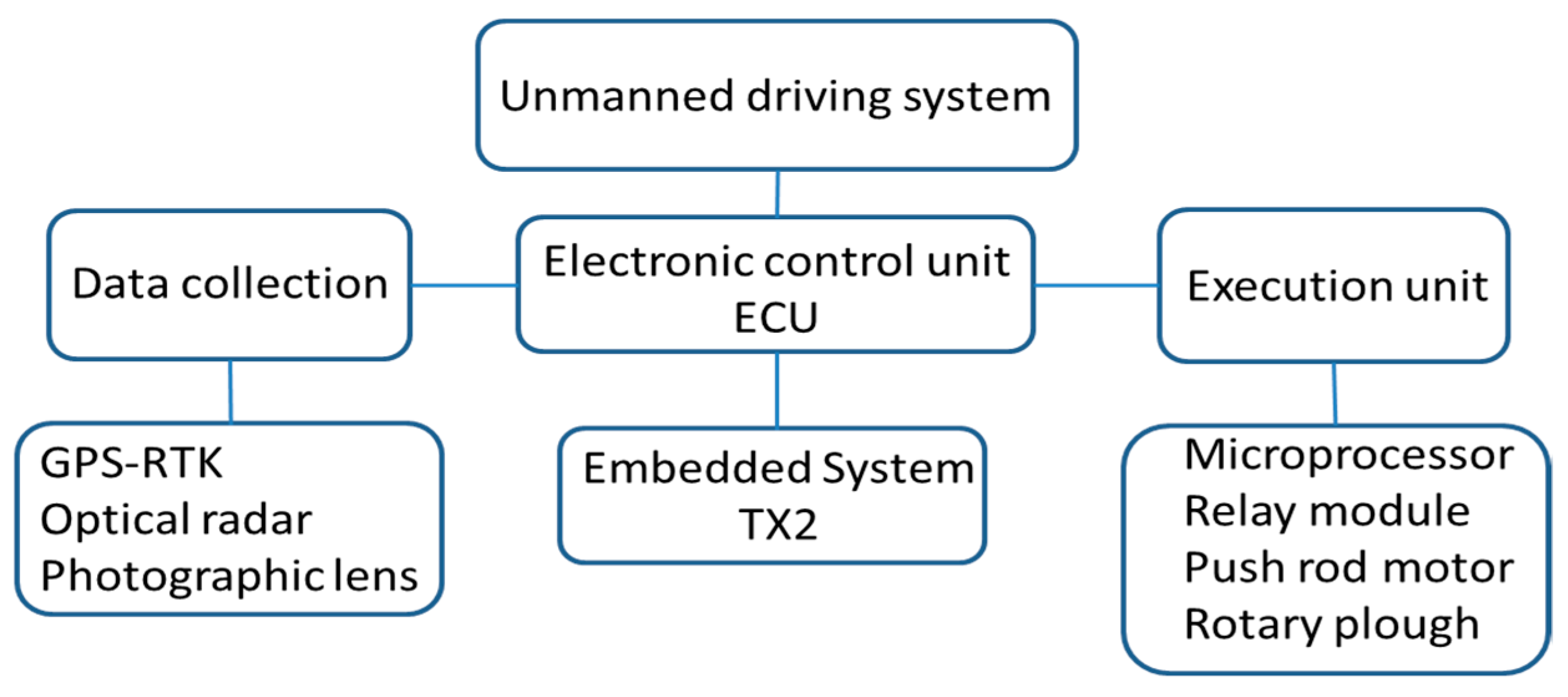
The unmanned driving system can be divided into three parts, information collection, electronic control unit (ECU), and execution unit. The information collection part refers to the sensing components. Different sensors collect information for different systems. The information collected by the sensors will be transmitted to the ECU for analysis and processing, and commands are given based on the results calculated by the ECU for the Execution unit. Figure 14 is a diagram of the unmanned driving system.
The positioning system used two GPS-RTK. The two were aligned in parallel, one was set at the center of gravity of the vehicle and the other was set at the back of the car. The two GPS-RTK collect the difference between the current heading angle and the heading angle toward the target point. A PID controller receives the angle error from the GPS-RTK, determines whether the vehicle should drive, spin, or stop, and tracks the target point with a GPS-RTK located at the center of gravity to achieve autonomous driving. The tractor uses LiDAR for obstacle avoidance and navigation assistance. The rotary plow carried by the tractor is dangerous. The LiDAR scans 360 degrees around the tractor to stop the tractor when an object enters the hazard zone, which was redefined, and to prevent something from getting caught in the rotary plow.
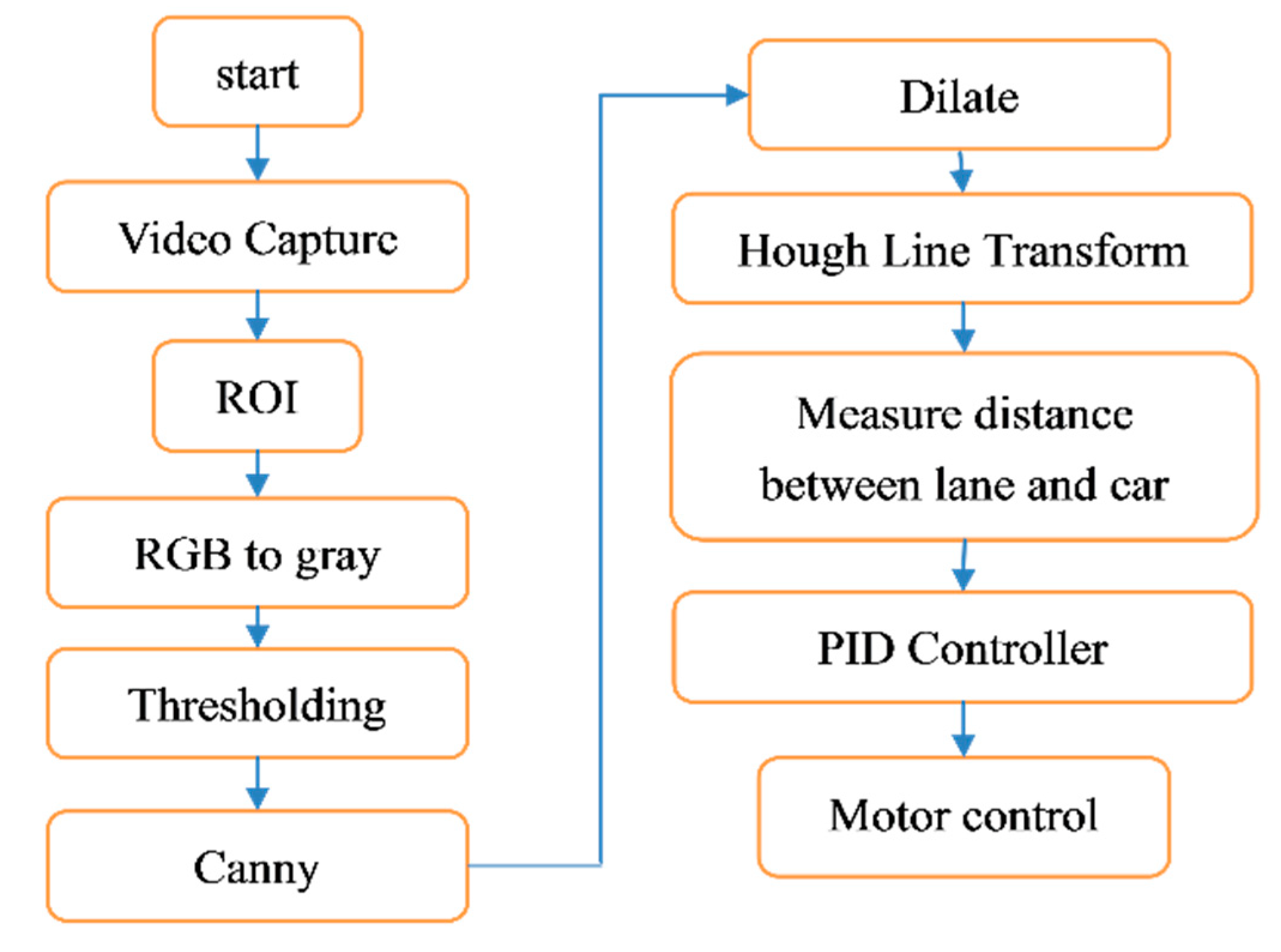
To assist the autonomous vehicle to touch the ground in excessive ups and downs, three optical radars were added in addition to the existing GPS-RTK. Two of the three optical radars were placed on the front left and right sides of the vehicle to detect both sides of the vehicle and to calibrate the lateral accuracy of the vehicle. The remaining optical radar was mounted in the front of the vehicle to detect obstacles. When an obstacle is detected within a defined distance in front of the vehicle, the operation of the vehicle will be stopped. The vehicle was also equipped with an image processing unit to keep the vehicle stable, as shown in Figure 15. After the camera captures the image, the desired targets in the region of interest (ROI) are processed. The image is then converted to grayscale and binarized. Then the Canny tracks the edges of the objects and performs dilate processing. Then, Hough transfers the edges to calculate the centerline of the road as the driving trajectory.
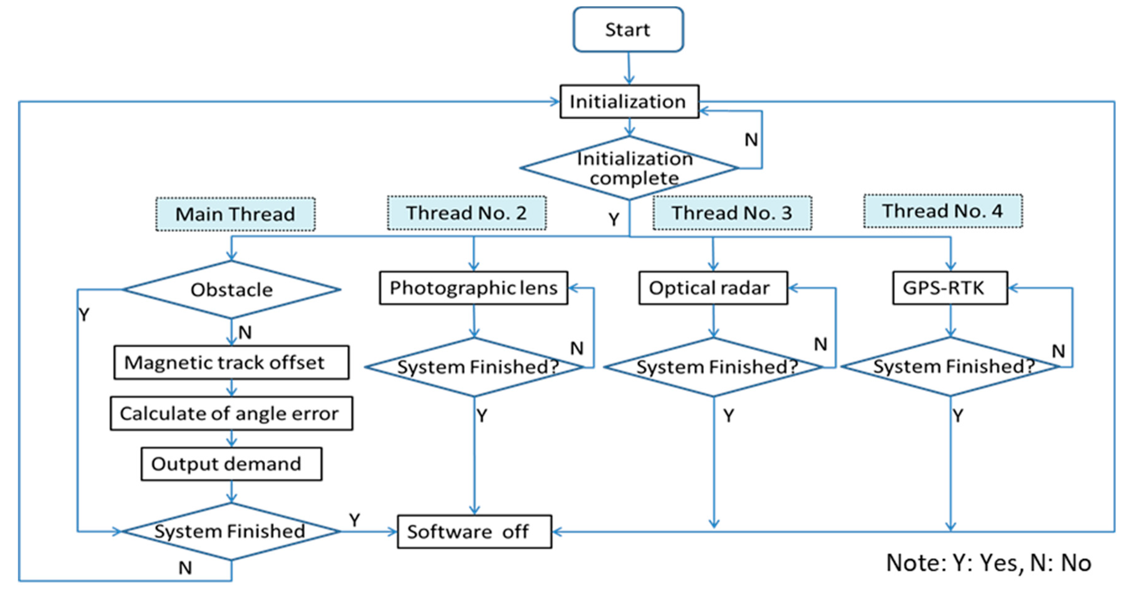
The vehicle control uses a NVIDIA TX2 to collect all the information from sensors, calculate the vehicle offset, the current position, and actuation function, and to send signals to the corresponding MCUs through the CAN bus to the control motors. The control system flow chart is shown in Figure 16.

4.3. Vehicle System Integration and Function Testing

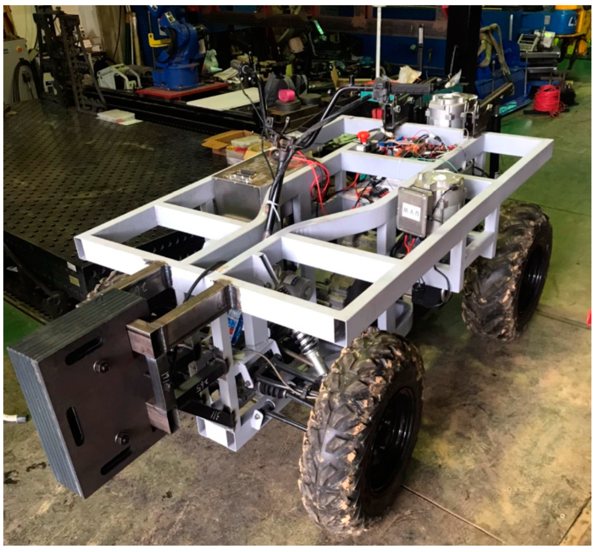
The Smart Farm of Pingtung University of Science and Technology was selected for the functional test of the tractor, as shown in Figure 17. The field is a 10 hectares smart agricultural production demonstration base. The crops in the field can be planted and cultivated according to research needs. In this study, both dry and wet arable land was used for field testing. The greenhouse was also one of the indispensable test areas. Figure 18 is the configuration diagram of the vehicle control system. The software architecture was divided into manual mode and automatic mode. In the manual mode, the operator gave the accelerator signal to the motor controller to achieve the driving requirement, and the steering signal was transmitted to the electronic assisted steering system to steer the whole vehicle. The automatic driving mode processed and captured the current position data at the first second, calculated the driving route with the current position and the set driving route, and then informed the controller and the electronic assisted steering system to make the tractor follow the route. Figure 19 is the completed diagram of the small electric tractor of the study.

5. Conclusions

This study focused on the development of a small electric tractor with complete design and fabrication of the whole vehicle system. The conceptual design of a lightweight vehicle body was obtained through topological optimization analysis and the finite element model analysis, which was used to obtain the rigidity, strength, and fatigue life analysis of the vehicle body. Finally, the vehicle body structure, chassis, and electrical system were completed with the integration of the vehicle control system. Based on the results of the above analysis, the following conclusions can be summarized:
  • According to the lightweight analysis process, the weight of the proposed vehicle body was 101 kg, and the bending and torsional rigidity were 11,579 N/mm and 4923 N·m/deg, respectively.
  • In the analysis of the bending, torsion, and full load braking strength of the vehicle body, the maximum von-Mises stress was lower than the material yield strength by 2/3, which met the design requirements.
  • The fatigue life analysis showed that the fatigue life of the designed vehicle body reached 6.5 × 10⁸ km when driven on a general asphalt road at a speed of 18 km/h. When rotating or plowing at a speed of 2 km/h, the fatigue life reached 11,190 km and 23,166 km, respectively.
  • This research completed the development and fabrication of a small electric tractor, which met the requirements of manual driving and automatic driving. In addition, the tractor was equipped with two 7.5 kW induction motors, driven by lithium batteries, which can achieve at least 3.5 h of working time, and the rotary tillage operations can reach a depth of about 15 cm. The result of field tests on the prototype electric tractor are shown in Table 5, Table 6 and Table 7.

Author Contributions

Y.-C.C., M.-Y.C. and L.-W.C. conceived the idea. We developed the theory and Y.-C.C. performed the CAE. L.-W.C. developed the control. M.-Y.C. and Y.-C.C. verified the analytical methods and supervised the findings of this work. All authors discussed the results and contributed to the final manuscript. All authors have read and agreed to the published version of the manuscript.

Funding

This research was funded by the Pingtung University of Science and Technology (NPUST).

Institutional Review Board Statement

Not applicable.

Informed Consent Statement

Not applicable.

Acknowledgments

We thank Pingtung University of Science and Technology (NPUST) for funding implementation and providing the venue for the experiment.

Conflicts of Interest

The authors declare no conflict of interest.

References

  1. Ji, W. Research on the Application of Automotive New Energy and Energy-saving Technology. Sci. Technol. Wind. 2013, 8, 104. [Google Scholar]
  2. Carlini, M.; Abenavoli, R.I.; Kormanski, H.; Rudzinska, K. A Hybrid Electric Propulsion System for a Forest Vehicle. In Proceedings of the Energy Conversion Engineering Conference, Honolulu, HI, USA, 27 July–1 August 1997; p. 5926956. [Google Scholar]
  3. Florentsev, S.; Izosimov, D.; Makarov, L.; Baida, S.; Belousov, A. Complete Traction Electric Equipment Eets of Electro-Mechanical Drive Trains for Tractors. In Proceedings of the IEEE Region 8 International Conference on Computational Technologies in Electrical and Electronics Engineering, Irkutsk, Russia, 11–15 July 2010; pp. 611–616. [Google Scholar]
  4. Xiao, S. Development Status and Trends of Light Electric Agricultural Transport Machinery. Agric. Dev. Equip. 2012, 3, 49–50. [Google Scholar]
  5. Yu, Z. Research on Human-Machine System Design of Greenhouse Electric Walking Tractor. Master’s Thesis, Institute of Mechanical Engineering, Nanjing Agricultural University, Nanjing, China, 2013. [Google Scholar]
  6. Guan, C.S.; Hu, H.; Chen, Y.S.; Yang, Y.T.; Cao, S.M. Study on Small Electric Tractors for Greenhouses. China J. Agric. Mech. 2015, 36, 67–69. [Google Scholar]
  7. Troncon, D.; Alberti, L. Case of Study of the Electrification of a Tractor: Electric Motor Performance Requirements and Design. Energies 2020, 13, 2197. [Google Scholar] [CrossRef]
  8. Gao, Y.; Wang, X.; Li, J. Optimization Design of Electric Tractor for Small Seeding Machinery. In Proceedings of the 3rd International Conference on Automation, Mechanical and Electrical Engineering, Shanghai, China, 22–23 July 2018; pp. 59–63. [Google Scholar] [CrossRef]
  9. Sitompul, J.; Zhang, H.; Noguchi, T.; Ahamed, T. Optimization study on the design of utility tractor powered by electric battery. IOP Conf. Ser. Earth Environ. Sci. 2019, 355, 012058. [Google Scholar] [CrossRef]
  10. Franceschetti, B.; Rondelli, V.; Capacci, E. Lateral Stability Performance of Articulated Narrow-Track Tractors. Agronomy 2021, 11, 2512. [Google Scholar] [CrossRef]
  11. Xu, J.; Li, R.; Li, Y.; Zhang, Y.; Sun, H.; Ding, X.; Ma, Y. Research on Variable-Universe Fuzzy Control Technology of an Electro-Hydraulic Hitch System. Processes 2021, 9, 1920. [Google Scholar] [CrossRef]
  12. Askari, M.; Abbaspour-Gilandeh, Y.; Taghinezhad, E.; El Shal, A.M.; Hegazy, R.; Okasha, M. Applying the Response Surface Methodology (RSM) Approach to Predict the Tractive Performance of an Agricultural Tractor during Semi-Deep Tillage. Agriculture 2021, 11, 1043. [Google Scholar] [CrossRef]
  13. Moinfar, A.; Shahgholi, G.; Abbaspour-Gilandeh, Y.; Herrera-Miranda, I.; Hernández-Hernández, J.L.; Herrera-Miranda, M.A. Investigating the Effect of the Tractor Drive System Type on Soil Behavior under Tractor Tires. Agronomy 2021, 11, 696. [Google Scholar] [CrossRef]
  14. Du, J.; Heng, Y.; Zheng, K.; Zhang, W.; Zhang, J.; Xia, J. Evaluation of the Performance of a Combined Tillage Implement with Plough and Rotary Tiller by Experiment and DEM Simulation. Processes 2021, 9, 1174. [Google Scholar] [CrossRef]
  15. Cheng, J.; Zheng, K.; Xia, J.; Liu, G.; Jiang, L.; Li, D. Analysis of Adhesion between Wet Clay Soil and Rotary Tillage Part in Paddy Field Based on Discrete Element Method. Processes 2021, 9, 845. [Google Scholar] [CrossRef]
  16. Li, X.; Wei, B.; Xu, X.; Zhou, J. Effect of Deep Vertical Rotary Tillage on Soil Properties and Sugarcane Biomass in Rainfed Dry-Land Regions of Southern China. Sustainability 2020, 12, 10199. [Google Scholar] [CrossRef]
  17. Lygouras, E.; Gasteratos, A. A novel moving-base RTK-GPS-Based wearable apparatus for precise localization of humans in peril. Microprocess. Microsyst. 2021, 82, 103833. [Google Scholar] [CrossRef]
  18. Yu, W.; Peng, H.; Pan, L.; Dai, W.; Qu, X.; Ren, Z. Performance assessment of high-rate GPS/BDS precise point positioning for vibration monitoring based on shaking table tests. Adv. Space Res. 2021. [Google Scholar] [CrossRef]
  19. Gutmann, E.D.; Larson, K.M.; Williams, M.W. Snow measurement by GPS interferometric reflectometry: An evaluation at Niwot Ridge, Colorado. Hydrol. Process. 2012, 26, 2951–2961. [Google Scholar] [CrossRef]
  20. Zhao, L.; Qiu, H.; Feng, Y. Analysis of a robust Kalman filter in loosely coupled GPS/INS navigation system. Measurement 2016, 80, 138–147. [Google Scholar] [CrossRef]
  21. Amini, A.; Vaghefi, R.M.; Jesus, M.; Buehrer, R.M. Improving GPS-based vehicle positioning for intelligent transportation systems. In Proceedings of the 2014 IEEE Intelligent Vehicles Symposium Proceedings, Dearborn, MI, USA, 8–11 June 2014; pp. 1023–1029. [Google Scholar]
  22. Gao, H. Research on Electric Tractor Drive System. Ph.D. Thesis, College of Engineering, Nanjing Agricultural University, Nanjing, China, 2008. [Google Scholar]
Figure 1. Planning of the division for vehicle design.
Agriculture 12 00112 g001
Figure 2. System configuration of the electric tractor.
Agriculture 12 00112 g002
Figure 3. Power system configuration of the small electric tractor.
Agriculture 12 00112 g003
Figure 4. Space planning of car body, (a) Side view; (b) Top view.
Agriculture 12 00112 g004
Figure 5. Analysis process of the lightweight design of the small electric tractor.
Agriculture 12 00112 g005
Figure 6. The finite element model of the vehicle body prototype.
Agriculture 12 00112 g006
Figure 7. The design area of the vehicle body prototype.
Agriculture 12 00112 g007
Figure 8. Load conditions on the prototype of the vehicle body.
Agriculture 12 00112 g008
Figure 9. Finite element model of the suspension system. (a) Front suspension; (b) Rear suspension.
Agriculture 12 00112 g009
Figure 10. Material distribution of car body.
Agriculture 12 00112 g010
Figure 11. Boundary conditions for fatigue life analysis.
Agriculture 12 00112 g011
Figure 12. Analysis of driving on a C-level road at = 2 km/h during rotary tillage operation. (a) Von-Mises stress distribution; (b) the von-Mises stress of the car body where σe,max occurs; (c) stress amplitude and number of average stress; and (d) fe-safe life simulation.
Agriculture 12 00112 g012
Figure 13. Analysis of driving on D-class road surface at = 2 km/h during rotary tillage operation. (a) Von-Mises stress distribution; (b) the von-Mises stress of the car body where σe,max occurs; (c) stress amplitude and number of average stress; and (d) fe-safe life simulation.
Agriculture 12 00112 g013
Figure 14. Unmanned driving system.
Agriculture 12 00112 g014
Figure 15. Image processing and control flowchart.
Agriculture 12 00112 g015
Figure 16. Control system flowchart.
Agriculture 12 00112 g016
Figure 17. Smart Farm of Pingtung University of Science and Technology.
Agriculture 12 00112 g017
Figure 18. Configuration of vehicle control system.
Agriculture 12 00112 g018
Figure 19. The small electric tractor.
Agriculture 12 00112 g019
Table 1. Vehicle parameters of the electric tractor.
Vehicle Parameters
LengthWidthHeight
1720 mm1100 mm660 mm
Tire sizeTotal vehicle weight
Front 26 × 8-14Rear 26 × 10-14650 kg
Table 2. Material properties.
Type ParameterSPFH 590STKM 11A
Density (kg/m3)78507850
Young’s Modulus (MPa)210210
Yielding Stress (MPa)420175
Ultimate Stress (MPa)590290
Poisson’s Ratio0.30.3
Table 3. Spring stiffness and damping coefficient value of suspension system.
Front SuspensionRear Suspension
Spring Constant (N/mm)27.5 (Kf)27.5 (Kr)
Damping Coefficient (N.s/mm)0.96 (Cf)2.16 (Cr)
Table 4. Selected motor specifications.
Rated VoltageDC72V
Rated power7.5 kW
Instantaneous peak17.8 kW
Maximum speed5800 rpm
Maximum torque23.2 N-m
Table 5. Field tests on different kinds of road.
Field Test
Velocity (km/h)Road TypeCurrent (A)Power (W)
3.05Asphalt2.38185.64
Hard7.3569.4
Soft3.83298.74
Grass2.5195
1.02Asphalt14.161104.48
Hard26.02028
Soft10.85846.3
Grass16.71302.6
The current of the drive motor test on the soft soil in the field was the largest, with a low speed of 7.3 A and a high speed of 26 A.
Table 6. Influence of driving speed and tillage on motor power.
Velocity (km/h)Depth (cm)Driving CurrentTillage Current
Current (A)Power (W)Current (A)Power (W)
1.02510.9850.228.12191.8
107.9616.232.82558.4
1512.91006.237.42917.2
3.05525.72004.644.33455.4
1028.22199.649.13829.8
1537.22901.652.24071.6
Table 7. Influence of motor power consumption on battery discharge time.
Drive Current and Tillage Current (A)
Low speed 1.02 (km/h)50.3 A
High speed 3.05 (km/h)126.6 A
Ploughing field 15 cm, for low-speed, the current was 50.3 A, for high-speed, the current was 126.6 A.
Publisher’s Note: MDPI stays neutral with regard to jurisdictional claims in published maps and institutional affiliations.