Article

Development of an Air-Recirculated Ventilation System for a Piglet House, Part 2: Determination of the Optimal Module Combination Using the Numerical Model

1
Department of Rural Systems Engineering, Research Institute for Agriculture and Life Sciences, College of Agriculture and Life Sciences, Seoul National University, 1, Gwanakno, Gwanakgu, Seoul 08826, Korea
2
Department of Rural Systems Engineering, Research Institute for Agriculture and Life Sciences, Global Smart Farm Convergence Major, College of Agriculture and Life Sciences, Seoul National University, 1, Gwanakno, Gwanakgu, Seoul 08826, Korea
3
Research Institute of Green Eco Engineering, Institute of Green Bio Science and Technology, Seoul National University, 1477, Pyeongchang-daero, Daehwa-myeon, Pyeongchang-gun 25354, Korea
4
Department of Smart Farm Engineering, College of Industrial Sciences, Kongju National University, 54, Daehak-ro, Yesan-eup, Yesan-gun 32439, Korea
5
Wageningen Livestock Research, Wageningen University and Research, De Elst 1, 6708 WD Wageningen, The Netherlands
*
Author to whom correspondence should be addressed.
Agriculture 2022, 12(10), 1533; https://doi.org/10.3390/agriculture12101533
Submission received: 29 June 2022 / Revised: 1 September 2022 / Accepted: 20 September 2022 / Published: 23 September 2022
(This article belongs to the Section Farm Animal Production)

Abstract

:
As the pig industry develops rapidly, various problems are increasing both inside and outside pig houses. In particular, in the case of pig houses, it is difficult to solve the main problems even if automation and mechanization are applied with Information and Communications Technologies (ICT). The air recirculation technology can be applied as a technology that can solve these typical problems in the pig industry, such as growth environment, livestock disease, odor emission, energy cost, and pig productivity. The air recirculated ventilation system (ARVS) can minimize the inflow of air from the outdoors and recycle the internal thermal energy of the pig house. The ARVS consists of (1) an air scrubber module, (2) an external air mixing module, (3) a UV cleaning module, (4) a solar heat module, and (5) an air distribution module. In this study, the growth environment of piglets was predicted using a numerical model when the ARVS was applied. Since the concept of air recirculation was used, numerous equations for predicting the internal environment should be iteratively calculated. Furthermore, it was necessary to determine the optimum condition of the modules by applying various boundary conditions. Therefore, the model was designed for numerical analysis based on the balance equations of environmental factors inside the piglet room. For each module, the module coefficient and equations were considered based on the previous studies. The analysis was conducted according to the system diagram of each module, and the growth environment inside the piglet room was evaluated according to the various environmental conditions. As a result of calculating the numerical model, the ventilation rate of 40 CMM or more was advantageous to properly maintaining the gas environment. In the summer season, it was necessary to additionally use the cooling device and dehumidifier. In the winter season, when using a heat exchanger and solar module, was more advantageous for maintaining air temperature inside the piglet room.

1. Introduction

The livestock industry in South Korea has been an important industry in agriculture for a long time. The domestic livestock industry continues to grow due to the increase in the demand for meat, accounting for about 39.4% of the total agricultural production [1]. In particular, in the pig industry, which occupies the highest proportion in the livestock industry, the number of breeding heads per farm is increasing every year, while the number of pig farms is decreasing due to the enlargement and intensive production of pig houses. Compared with other livestock facilities, pig houses generally have a lot of pollutants such as dust, odor, and harmful gas accumulated inside the pig house. As the size of the pig house increases, it is becoming more and more difficult to maintain the appropriate environment inside the pig house due to the occurrence of problems related to the stability and uniformity of the internal environment. Therefore, the demand for technologies for controlling and managing the internal environment of the pig house has continuously increased.
Although the pig industry has been actively automated and mechanized by applying ICT technology in recent years, it is still difficult to solve the fundamental problems of pig farms [1]. Accordingly, disputes between local residents and farm owners constantly occur, considering various environmental and social problems in the pig industry. The widely known current challenges to be solved in the pig industry include (1) prevention of livestock disease [2], (2) reduction of livestock odor emission [3], (3) improvement of the livestock breeding environment [4], (4) improvement of farm management and reduction of the operation cost [5], (5) reducing the energy cost of livestock [6], and (6) improving quality of livestock products [7].
Air recirculation technology is a technology that minimizes the inflow of outside air and uses the internal air, which is cleaned by a wet scrubber system. The reason for using the recirculated air is to reuse the thermal energy inside the pig house. This technology is widely investigated in industrial environments to save air conditioning costs by recycling the energy inside buildings [8,9,10,11,12,13]. In particular, standards for air recirculation have been developed in general industrial processes, and the allowable concentration standards for hazardous substances in reused air are suggested [14]. If air recirculation technology is applied to pig houses, it is possible to minimize the possibility of livestock infectious diseases because it can block the airborne transmission of disease [15]. Since the pig house can be operated and managed in a closed state, infectious diseases through wild animals can be minimized. In the winter season, minimum ventilation is operated to reduce the heating load in the pig house. As a result, the breeding environment in the pig house, such as the high level of dust and various harmful gases, can be very poor. The air recirculated ventilation system (ARVS) can improve the breeding environment by increasing the ventilation rate and using the recirculated air. In addition, it is possible to minimize the emission of odors from the pig house. Accordingly, various studies have been conducted to apply air recirculation technology to pig houses [16,17,18,19,20]. Lau, et al. [21] devised a method of recirculating air by removing dust by using a fabric filter and an electrostatic dust collector. Although the concentration of dust in pig houses could be reduced by up to 60% or more, it was difficult to satisfy the allowable concentration standards. Anthony, Yang, and Peters [19] analyzed the concentration of dust and carbon dioxide inside the pig house when the air recirculation system was applied in farrowing pig room and reported that the air recirculation system could be an alternative to prevent the deterioration of workers’ health. Wenke, et al. [22] analyzed that when a filter was installed in the air recirculation system, the dust concentration was the lowest, and the pig’s lung health was excellent. Peters, et al. [23] evaluated the performance by applying the shaker dust collector to the air recirculation system, and Park, Peters, Altmaier, Jones, Gassman, and Anthony [20] simulated the effect of the concentration of pollutants in the pig house using mass and energy balance equations. Mostafa, et al. [24] applied an air scrubber module to the air recirculation system and reported that wet scrubber technology could reduce both ammonia gas and dust concentrations and has no negative effect on pigs. Despite the research on the application of air recirculation systems in pig houses, there are few studies that evaluate the internal environment, such as air temperature, humidity, gas, dust, and odor. In addition, previous studies on air scrubber systems have been conducted to evaluate the effect in terms of deodorizing and reducing harmful gases in pig houses. However, there is no current study that focuses on designing an air conditioning system to prevent livestock disease by recirculating air. In particular, there is no present research related to analyzing the complex environment inside and outside the pig house through the installation of ARVS, including the wet scrubber module to improve the internal environment, reduce energy load, improve energy recovery rate, and reduce exhaust gas and odor. The Aero-Environment Energy Engineering Laboratory (A3EL) of Seoul National University in South Korea has been developing an ARVS to be installed in an experimental pig house for five years since 2018. Figure 1a shows the structure of a conventional ventilation system operated in a pig house. It is a system that controls the ventilation rate based on the internal temperature, exhausts internal heat, moisture, gas, and dust. Figure 1b, on the other hand, shows the schematic diagram of various modules in the ARVSs, such as the wet scrubber module, the outdoor air mixing module, and the heat exchange module. Deriving an equation for the ARVS, an analysis of the combination of the various modules was conducted.
Modules applicable to the ARVS can be combined in various ways depending on the purpose. In this study, the growth environment of piglets was predicted using a numerical model when the ARVS was applied. Since the concept of air recirculation was used, numerous equations for predicting the internal environment should be iteratively calculated. In addition, it was necessary to determine the optimum condition of the modules by applying various boundary conditions. Therefore, the internal environment of pig houses installed with ARVS was evaluated, and the optimal model of ARVS was designed using the numerical model developed in this study. The internal environment of the pig house was analyzed based on the various balance equations. The ARVS could consist of various modules. Based on the numerical model developed in this study, the internal environment of the pig house was evaluated. In addition, it was attempted to derive the optimal design standard of the ARVS.

2. Materials and Methods

In this study, a numerical model was developed for the optimal design of the ARVS. First, the numerical model was developed to calculate the internal environment, such as heat, moisture, and gas balance equations inside the pig house (Figure 2). The model of the recirculating air required iterative calculation because the environment inside the pig house was calculated by the balance equations after the air was used again. This iterative calculation was conducted many times according to the various environmental conditions. Therefore, the calculation to predict the environment inside the piglet room was developed as a numerical model. For the validation of the designed numerical model, the measured data of the thermal environment inside the experimental piglet room were used. Heat loss was selected as a thermal environment validation variable. The calibration was conducted according to the amount of heat loss to reduce the error value between the computed result and the measured temperature data. In developing the numerical model, the configuration of the ARVS, such as the wet scrubber module, external air mixing module, heat exchange module, and solar module, were considered. These modules linked to the numerical model of the base module that completed the validation of the thermal environment. Based on these results, numerical model calculations were conducted according to external weather conditions. The internal environment of the pig house was evaluated, and an optimal design for the experimental piglet room was suggested.

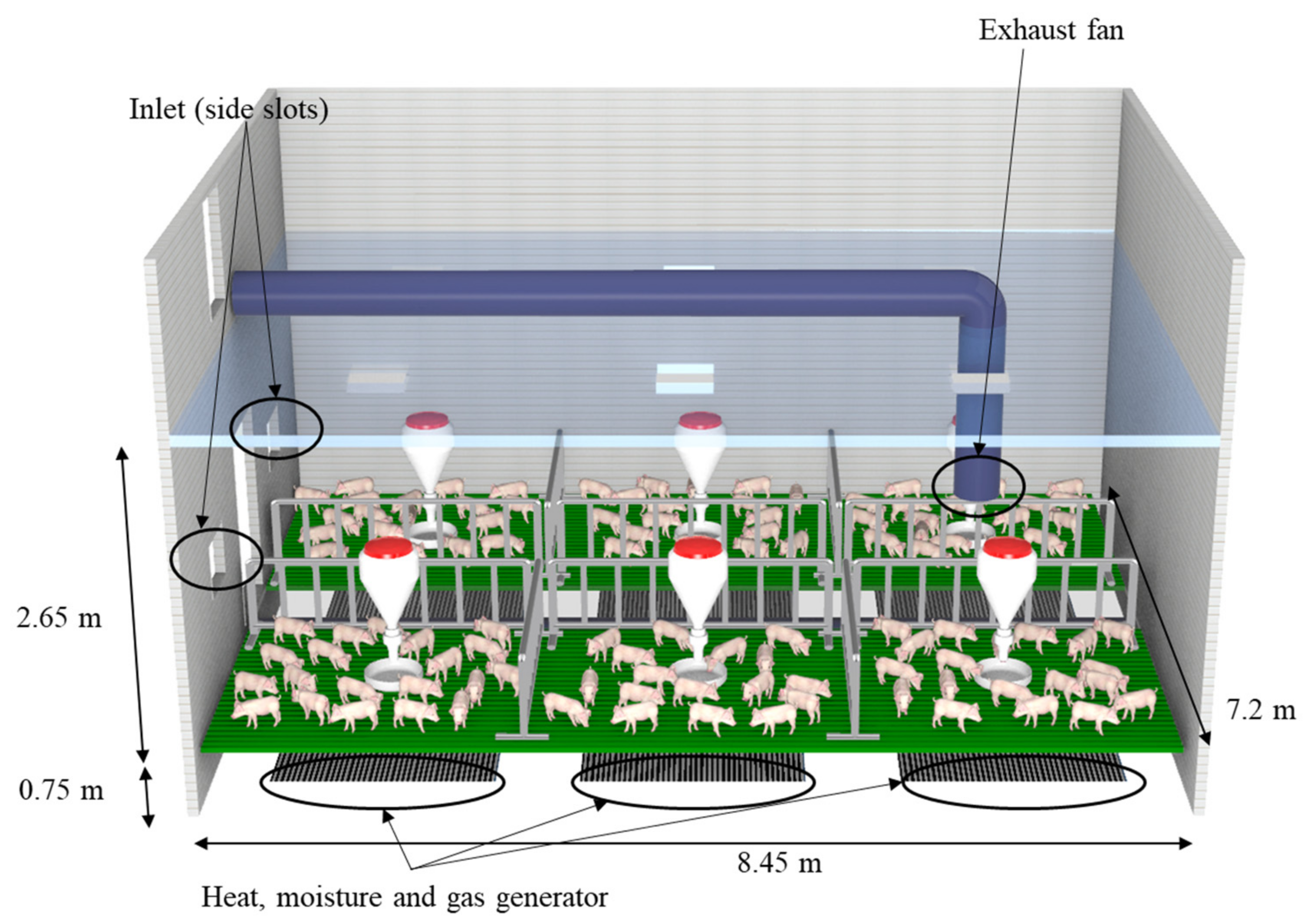
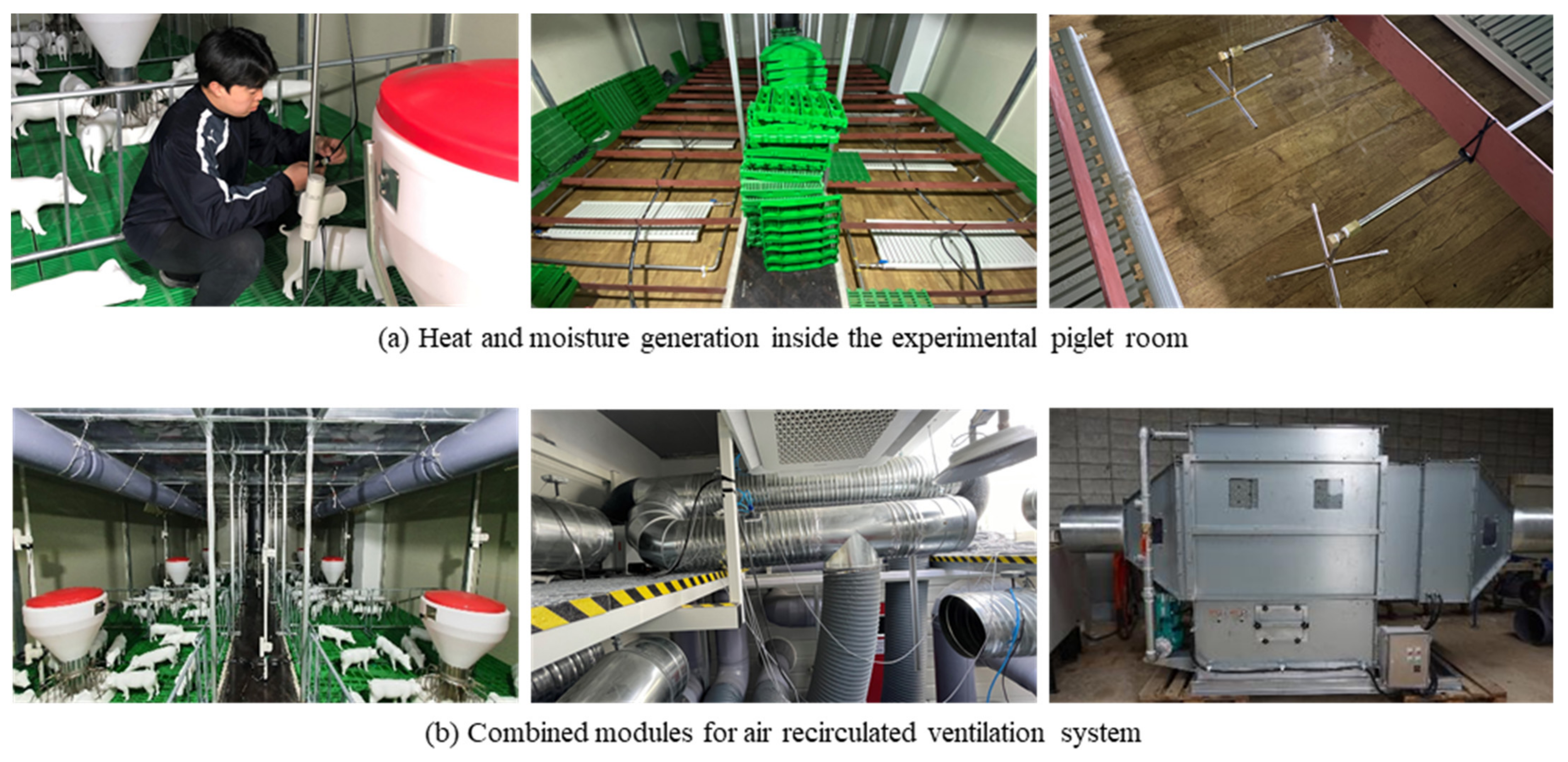
2.1. Target Facility

Using the result of this study, an actual ARVS developed will be installed on a real farm. Thus, the main purpose of this study is to suggest an optimal design based on a combination of several modules that will provide an optimal design of the ARVS. In order to determine the optimal design of the ARVS in this study, the validation and calculation of the numerical model were conducted first in the test bed. The target test bed for the numerical design of the ARVS was in the Artificially Controlled Smartfarm Engineering Center of Aero-Environmental and Energy Engineering Laboratory (AcSEC-A3EL), located at the College of Agriculture and Life Sciences, Pyeongchang Campus, Seoul National University (latitude 37°54′87″ N, longitude 128°43′57″ E). The target facility was designed according to the 2016 Pig House Architectural Design Manual [25] (Figure 3). In general, on pig farms, access is limited due to livestock disease control. Additionally, it is impossible for researchers to artificially set the experimental environment because the farmers are reluctant to change their operating environment inside the pig house. To overcome the limitations of the field experiments in actual pig farms, the target facility was constructed so that all indoor and outdoor environmental factors could be artificially controlled. The reason why AcSEC-A3EL was selected as the experimental pig room in this study was to first design the ARVS numerically and then manufacture all the modules of the ARVS based on the results from the numerical design later. After the manufactured module was installed in the target facility, experiments were conducted to validate and supplement the results of this study. After the validation of this scale-down stage, the developed ARVS will be installed in the actual pig farm. Through this scale-down development stage, it was attempted to prevent failures or problems that could occur in advance.
Figure 3 below is a schematic diagram of the experimental piglet room. It was assumed that a total of 174 piglets (7 weeks old) were raised based on a breeding density of 0.3 m2·head−1. Three-dimensional artificial piglets were also added to the experimental piglet room to reflect realistic airflow. The size of the experimental piglet room was 6.7 m in width, 9.5 m in length, and 2.5 m in height, according to domestic standards. The floor of the experimental piglet room consisted of a plastic pit. The heat inside the piglet room can be exchanged through the wall. The total heat radiant area of the wall was 196.5 m2, and the wall of the experimental piglet room was equipped with the thermal insulation plate type (No. 1), so the thermal conductivity was set to 0.036 W·m−1·°C−1 in the numerical model of this study. Various outlets such as chimney exhaust fan, sidewall exhaust fan, and pit exhaust fan were installed inside the experimental piglet room. Additionally, various inlets, such as sidewall slots, ceiling slots, and pit inlets, were installed. In this study, the chimney exhaust fan and the side slots were used for the experiment. The actual airflow rate at the outlets was measured with the pressure sensor, designed remotely and quantitatively monitor the real-time ventilation rate. In addition, heat, moisture, and gas generators were installed in the slurry pit under the floor of the experimental piglet room, so it was possible to experiment while artificially controlling the heat, moisture, and gas generation rate of the piglets (Table 1).

2.2. Balance Equations of Environment inside the Experimental Piglet Room

In this study, the growth environment inside the experimental piglet room was simulated considering the air temperature, moisture, and gas balance equations. The change of state of humid air was calculated using the equation specified in The ASHRAE Handbook—Fundamentals [27]. The heat generation of the electricity use and sensible heat loss due to water evaporation were excluded from the calculation because only the heat produced by the piglets should be considered in the thermal balance equation. Accordingly, the thermal balance equation included the inflow and outflow of heat by ventilation, the sensible heat production of piglets, and the wall conduction. Moisture and gases generated inside the piglet room are mainly from the manure and floors. Accordingly, to quantify the heat, moisture, and gas balance equations, it was necessary to determine the heat, moisture, and gas generation rate inside the piglet room.
The total heat production of piglets can be expressed in Equation (1). Sensible heat production can be expressed in Equation (2) [26]. The heat production of piglets can be changed depending on the air temperature near the piglets because the piglets maintain homeostasis. Therefore, the equation of the heat production considering the piglet’s weight and feed intake constant includes the correction equation according to the air temperature near the piglets. The change of the heat production based on the 20 °C of air temperature was applied as a linear equation.
q t o t = 0.00086 × 7.4 m 0.66 + 1 0.47 + 0.003 m 7.4 n m 0.66 7.4 m 0.66 1000 + 12 20 t i
where, q t o t is the total heat production of piglets (kcal·h−1·head−1), m is the weight of the piglets (kg), n is feed intake constant, and t i is the air temperature inside the piglet room (°C).
q s = 0.00062 1000 + 12 20 t i 1.15 t i 6 × 10 7
where, q s is the sensible heat production of piglets (kcal·h−1·head−1).
The moisture generation rate of the piglets can be calculated from the latent heat generation and the latent evaporative heat of water, which is shown in Equation (3). In addition, the moisture generation rate from the manure and bottom of the piglet room was calculated using Equation (4) [28]. The moisture generation rate of the floor was determined by considering the ratio of the size of the piglet zone in the previous study to the size of the piglet zone in this study.
w a = q t o t q s λ
where, w a is the moisture generation rate of the piglets (kg·kg-da−1·h−1·head−1) and λ is the latent evaporative heat of water (kcal·kg−1).
w e = 3.6 0.224 t i 2.5469 N
where, w e is the moisture generation rate in a humid place (kg·kg-da−1·h−1·head−1).
The ammonia generation rate in the piglet room should consider various factors such as the number of piglets, manure treatment facilities, feed intake, internal air temperature, the airflow rate across the manure surface, and manure pH. Therefore, in this numerical model, the ammonia generation rate inside the piglet room was determined to be 0.000216 kg·h−1·head−1, according to the report’s results [29]. In general, the concentration of carbon dioxide has a high correlation with the respiration rate of livestock. As respiration increases, the exhalation rate increases, resulting in an increase in carbon dioxide emissions. Therefore, the carbon dioxide generation rate was applied by considering the number of piglets. Therefore, the carbon dioxide generation rate of the piglets can be expressed as Equation (5), considering the respiration rate according to the heat production of the piglets [30].
c a = 2.3 × 10 4 q t o t υ c
where, c a is carbon dioxide generation rate of the piglets (kg·h−1·head−1) and v c is the specific volume of the carbon dioxide (m3·kg−1).
In this study, various design conditions of the ARVS were considered. The air condition inside the piglet room for each environmental condition was calculated considering the temperature, moisture, and gas concentration balance equations. In the calculation, the air inside the piglet room is discharged and then passes through the ARVS. After that, the air flows into the piglet room. The air flowing into the piglet room passes through the ARVS, including a heat exchange module, a wet scrubber module, an outdoor air mixing module (controlling recirculated air and outdoor air), and a solar module. The total inflow air is equal to the sum of the recirculated air and the outdoor inflow air. The outdoor inflow air is the same as the amount of exhausted air from the outdoor air mixing module. From the thermal balance equation considering the heat production of piglets and the heat conducted through the wall, the air temperature inside the piglet room can be expressed as Equation (6) [31].
t i = t v v a q s N A U t i t o Q C p
where, t v is the inflow air temperature from the ARVS (°C), v a is the specific volume of the air inside the piglet room (m3·kg−1), A is the total heat radiant area (m2), U is the total heat transfer coefficient (kcal·m−2·°C−1·h−1), N is the number of piglets (head), t o is the outdoor air temperature (°C), Q is the ventilation rate (m3·h−1), and the specific heat at a constant pressure of internal air (kcal·kg−1·°C−1).
Even in the case of moisture, the moisture-containing air inflows to the piglet room after passing through the ARVS. The factor that affects the inflow of air is the wet scrubber module using the nozzles that spray water. Therefore, the amount of moisture in the air passing through the wet scrubber module and the moisture generation rate in the piglet room were considered. The amount of moisture inside the piglet room can be calculated with the following moisture balance equation [31] (Equation (7)).
w v = w i v a w a + w e N Q
where, w v is the absolute humidity of the inlet air of the piglet room (kg·kg-da−1·h−1), w i is the internal absolute humidity of the piglet room (kg·kg-da−1·h−1), w a is the absolute humidity of the wet scrubber module (kg·kg-da−1·h−1), and w e is the absolute humidity of the outdoor air (kg·kg-da−1·h−1).
In the case of the gas, the change of gas concentration occurs according to the mixing ratio of the outdoor air and the gas removal efficiency of the wet scrubber module, regardless of the characteristic of the ARVS. Ammonia gas can be removed from the wet scrubber module. However, carbon dioxide cannot be removed in the wet scrubber module [32]. Therefore, in the ammonia gas balance equation, the outdoor air mixing ratio and the ammonia gas removal efficiency of the wet scrubber module were considered. The concentration of carbon dioxide can be calculated by considering the external air mixing ratio. The two balance equations can be expressed as Equations (8) and (9) [31]. In this study, it was assumed that the ammonia gas removal efficiency of the wet scrubber module was 80% [32]. In addition, according to the 2016 standards of the piglet house [25], 20 ppm of ammonia concentration and 5000 ppm of carbon dioxide concentration were set as the limiting gas concentrations to evaluate the ARVS.
n i = 10 6 v n n a N Q 1 1 x m 1 η
c i = 10 6 c a v c N Q x m + c o x m
where, n i is the internal concentration of ammonia gas (ppm), v n is the specific volume of the ammonia gas (m3·kg−1), x m is the mixing ratio of the outdoor air, η is the removal efficiency of the wet scrubber module, c i is the internal concentration of carbon dioxide (ppm), and c o is the outdoor concentration of carbon dioxide (ppm).

2.3. Design Equation of the ARVS

The ARVS applied to the piglet room is a method in which the air exhausted from the piglet room is reused after cleaning the wet scrubber module. Therefore, it is necessary to clean the exhausted air to optimally control the air temperature, humidity, and gas concentration. In this study, various devices were investigated, and the suitability of the module was evaluated considering the economic feasibility, such as installation and operating costs. Based on these results, the wet scrubber module, the outdoor air mixing module, the heat exchange module, and the solar module were selected as the ARVS. Although the UV system is not a device for environmental control, it is also included in the module to be installed for disease control.
Based on the design equations of the ARVS, the wet scrubber module, outdoor air mixing module, heat exchange module, and solar heat exchanger module were implemented. Through these, the air temperature and relative humidity, and gas concentration inside the piglet room were evaluated. For the change in the state of the wet air, the equation for the change in the state of the wet air was referred to in The ASHRAE Handbook—Fundamentals [27]. When the air passes through the wet scrubber module, the air temperature and relative humidity can change. Equations (10) and (11) show the change in wet air when the air exhausted from the piglet room passes through the wet scrubber module [33]. According to the previous experimental results of the wet scrubber module, the adiabatic saturation efficiency was assumed to be 70%.
t w o = t w i η s × t w i t l
w w o = w w i η s w w i w l
where, t w o is the air temperature after passing the wet scrubber module (°C), t w i is the air temperature before passing the wet scrubber module (°C), η s is the adiabatic saturation efficiency (%), t l is the temperature of recirculation water (°C), w w o is the absolute humidity after passing the wet scrubber module (kg·kg-da−1), w w i is the absolute humidity before passing the wet scrubber module (kg·kg-da−1), and w l is the absolute humidity of recirculation water (kg·kg-da−1) (based on 100% relative humidity).
The heat exchange module and solar module all operate by sensible heat exchange. Equation (12) expressed the temperature exchange efficiency of each module. The temperature exchange efficiency coefficients were applied based on the results measured in the experiment. As a result of measuring the efficiency according to the flow rate, the average temperature exchange efficiency of 60% was calculated and applied in the numerical model. The heat storage tank is one of the equipment components of the solar module. The average temperature of hot water inside the heat storage tank was maintained at 60 °C depending on the daytime solar radiation. Therefore, it was assumed that the hot water flow rate was 5 L·min−1 and applied to the calculation as shown in Equation (13) below. Finally, the temperature and absolute humidity of the air mixed with the outdoor air were calculated based on the psychrometric chart.
t h o = t h i η t × t h i t r
t s o l a r + l = t s o l a r × Q s o l a r + t l × Q l Q s o l a r + Q l
where, t h o is the air temperature after passing the heat exchange module (°C), t h i is the air temperature before passing the heat exchange module (°C), η t is the heat exchange efficiency (%), t r is the water temperature before passing the heat exchange module (°C), t s o l a r + l is the mixed temperature of recirculated water and solar hot water (°C), t s o l a r is the temperature of solar hot water (°C), t l is the temperature of recirculated water (°C), Q s o l a r is the flow rate of solar hot water (L·min−1), and Q l is the flow rate of the recirculated water (L·min−1).

2.4. Numerical Design Condition of the ARVS

In this study, the numerical model of the ARVS was developed to evaluate the environmental condition inside the piglet room when the ARVS was installed. The numerical model was designed based on the temperature, moisture, and gas balance equations of the piglets and the ARVS modules. Python was used as the programming language, and the numerical model was developed using the PyCharm (Ver. 2019.2.1., JetBrains Inc., Prague, Czech Republic) software. The first condition considered in developing the numerical model was the structure of the ARVS. The module of the ARVS consists of the wet scrubber module, the outdoor air mixing module, the heat exchange module, and the solar module. Depending on the configuration of the module, the growth environment inside the piglet room can vary. As previously mentioned, carbon dioxide cannot be reduced in the wet scrubber module [32]. Thus, in this study, no module that can reduce carbon dioxide was considered in the ARVS. Since carbon dioxide can be continuously accumulated by the respiration of the piglets, it was essential to inflow the outdoor air for carbon dioxide balance. Therefore, to evaluate the combination of each module, the wet scrubber module and outdoor air mixing module were selected as basic modules for controlling the carbon dioxide. The wet scrubber module is a device that can reduce the concentration of dust, odors, and harmful gases in the exhaust air from the piglet room. The outdoor air mixing module is a device that conducts the mixing of the air according to the mixing ratio of the recirculated air and outdoor air. In other words, the amount of exhaust air is equal to the total amount of exhaust air from the piglet room, excluding the amount of recirculated air. It is equal to the amount of the inflow of air from the outside of the piglet room. The odors and harmful gases in the exhaust air should be removed. Therefore, the numerical model was developed to mix the outdoor air after passing through the wet scrubber module. On the other hand, the heat exchanger module and the solar module were selected as system variable conditions.

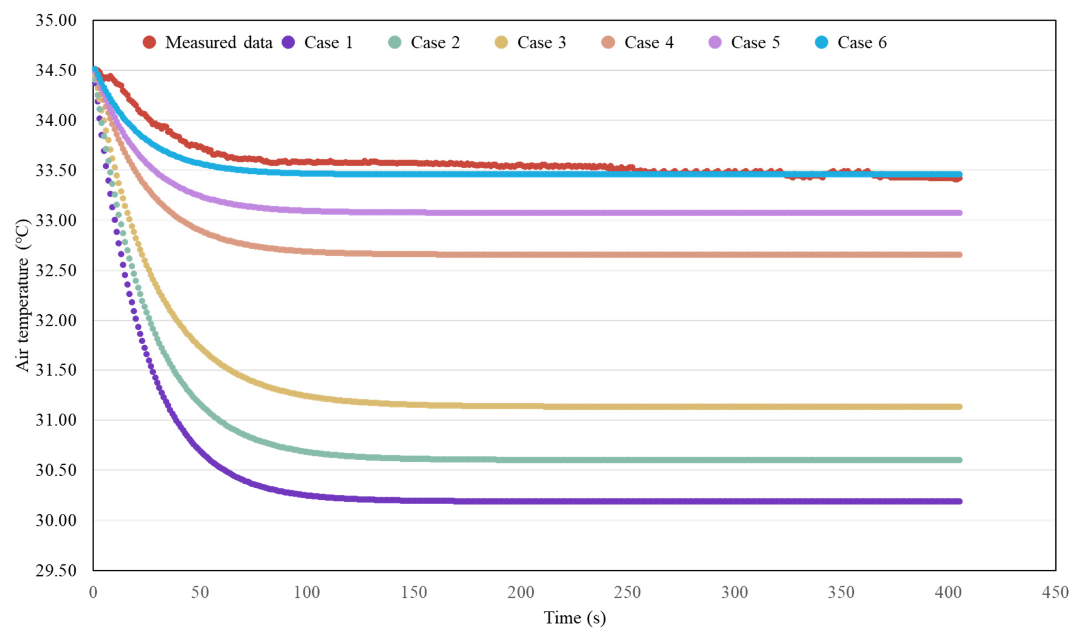
2.5. Validation of the Numerical Model of the ARVS

The validation experiment was conducted using the basic module of the ARVS in the testbed experimental piglet room (Figure 4). The numerical model of the ARVS was validated based on the thermal environment data for the basic module combination. The thermal environment simulation factors of the numerical model were the heat production of piglets, heat loss from the wall, temperature change due to recirculation water, and outdoor air inflow according to the outdoor air mixing ratio. The radiator was installed to generate the same heat production of the piglets, and the ventilation system and wall shape were considered the same as in the numerical model. The heat loss with uncertainty can be caused by infiltration or wall heat loss. In addition, since the ARVS is a semi-closed duct system, the ventilation rate can be reduced by the fan load. Since this was difficult to quantify in the numerical model, it was selected as a variable factor, and validation was conducted based on the measured data of temperature. Validation of the ventilation and wall heat loss for the basic module was conducted. The validation of uncertainty about other modules was not considered in the numerical model because the experimental data was used for the additional heat exchange and solar module. The thermal environment validation experiment of the basic module was conducted from August to September 2021. The validation experiment process was as follows. The heat production of the piglets was 4698 W based on the total number of piglets (174 heads) assumed in this study [26].
First, the radiator was operated using this condition, and the initial temperature inside the piglet room was maintained at 34.5 °C. After that, the ARVS was operated, and the outdoor air at 15 °C entered the experimental piglet room under the condition of the outdoor air mixing ratio of 10%. The exhaust fan was operated with a ventilation rate of 100 CMM (0.5 min−1) until the air temperature inside the experimental piglet room converged. As the input value of the numerical model, the ventilation structure conditions were set to be the same, and the basic heat production was set to be the same as the number of breeding heads. The validation variables were the amount of heat loss with uncertainty, and the case studies of the numerical model were selected according to the infiltration and ventilation rate. Generally, it is recommended that the crack area is within 10% of the total area in pig houses [25]. In this study, the ventilation rate considering the infiltration was applied as the standard of 10%. As a result of measuring the pressure while the exhaust fan was operated, the loss of ventilation rate was about 20%. Therefore, as shown in Table 2, the calculation of the numerical model for validation was conducted based on the six experimental conditions considering the infiltration rate and ventilation rate.
Descriptive statistics shown in the Table 3 were used for statistical analysis of the measured data and computed data of the experimental piglet room. Measured data and computed data were listed as time-series data. Therefore, mean bias error (MBE) was used to calculate the error according to the same time interval. In addition, root mean square error (RMSE) and coefficient of a variant of the RMSE (CV), which indicate accuracy, were used.

2.6. Case Studies with the Numerical Model of the ARVS

The efficiency of the ARVS was evaluated under various environmental conditions according to the configuration of the ARVS. The outdoor temperature, relative humidity, ventilation rate, and the mixing ratio of the outdoor air were considered as the environmental conditions, and these are shown in Table 4. A total of 10,800 cases were analyzed according to the combination of the ARVS module and environmental conditions. The condition of recirculating air only with the wet scrubber module was defined as the base module, and the mixing ratio of outdoor air can be controlled. The internal environment was analyzed according to the configuration of each heat exchange module, outdoor air mixing module, and solar module. In the case of the heat exchange module, it can be used as a method of exchanging heat with the air inside the piglet room (Figure 5 (1)) and a method of exchanging heat with the outdoor air (Figure 5 (2)).
After the combination of the modules was selected, the outdoor air condition was determined as a variable factor to calculate according to various environmental conditions. The meteorological data obtained from Wonju-si, Gangwon-do (37 ° 20′2″, 127 ° 55′5″) were used. The environmental conditions were set to include both extreme outdoor air temperature and relative humidity by sorting the data based on the meteorological data of the experimental piglet house. A total of 11 conditions of air temperature (−10, −5, 0, 5, 10, 15, 20, 25, 30, 35, 40 °C) at intervals of 5 °C was set to include the highest temperature and lowest temperature for outdoor temperature conditions. Furthermore, a total of 6 conditions of relative humidity (50, 60, 70, 80, 90, 100%) at intervals of 10% were set to include the highest and lowest relative humidity.

3. Results and Discussions

3.1. Design and Validation of the Numerical Model of the ARVS

The algorithm of the numerical design of the ARVS is shown in Figure 6. First, the air exhausted from the piglet room passed through all modules of the ARVS. All heat exchange and entropy conditions were considered at stage(A) (Figure 6), and the air condition before the inflow of the piglet room was calculated based on balance equations at stage (B). The air that passed through the ARVS inflowed to the piglet room. According to the module combinations, the cleaned air and outdoor air was mixed in the outdoor air mixing module, and the air temperature, humidity, and gas concentration could be calculated. Next, the air condition inside the piglet room was calculated from the balance equation of thermal, moisture, and gas by considering the reused air, the generation rate of environmental factors inside the piglet room, and heat exchange through the internal structure and the wall. The calculation of the numerical model was repeated until the calculated temperature, moisture, and gas of the air inside the experimental piglet room and the air exhausted from the piglet room converged, and the final result was analyzed at stage (c). The final result derived in this way means the growth environment inside the experimental piglet room when the combination of each module was applied. As shown in Table 4, for the numerical model of the ARVS, a total of 8 combined systems were designed. It was designed to calculate for all environmental conditions and to repeatedly calculate 1350 cases for each system at once through parallel processing. In a total of 10,800 cases, iteration operation was performed until A and C became the same value (Figure 6).
The validation result of the numerical model of the ARVS is shown in Figure 7. By generating the heat of 174 piglets using the radiator, about 4698 W of heat dissipation was maintained as sensible heat production in the experimental piglet room. After that, the ARVS was operated, and the internal temperature was maintained until a steady state was reached. Then, measured data of air temperature was used to compare with computed data of numerical model according to the variable values.
As can be seen in Figure 7, the measured air temperature converged from the initial temperature value of 34.5 °C to a temperature of about 33.5 °C over time. The amount of internal heat generated and the amount of heat loss converged due to the inflow of outdoor air. As a result of calculating the validation model, case 1 converged to a temperature of 30.2 °C, and there was a large difference compared with the measured air temperature. In case 1, the ventilation rate was set to 100 CMM, and the infiltration rate was 10%, so the amount of outdoor air inflow was very large. Accordingly, the air temperature convergence was observed as the lowest. In case 2 and case 3, the numerical model was calculated by reducing the infiltration rates to 5% and 1%, respectively. As a result of the calculation, the convergence temperature slightly increased to 30.6 °C and 31.2 °C, respectively. On the other hand, in case 4, case 5, and case 6, where the ventilation rate was lowered considering the load of the exhaust fan, the convergence temperature was calculated as 32.7 °C, 33.1 °C, and 33.5 °C, respectively. In the case of the lowest infiltration rate, the predicted result was the most similar to the measured temperature data. The reason for this was that the experimental piglet room had better airtightness than the general pig house, and there was almost no infiltration, so the effect of the heat loss due to infiltration was insignificant. In addition, when the load of the exhaust fan was considered, the thermal environment similar to the measured data was calculated. The load of the exhaust fan is easy to occur because the structure of the ARVS is a closed-loop duct ventilation system. In particular, the fan load was an important factor in the validation of this numerical model. The airflow loss due to the fan load can be about 10 to 20 times higher than the infiltration of the wall and cracks. Therefore, in case 6, where the load of the exhaust fan was considered, and the effect of the infiltration rate was reduced, the convergence value of the numerical model was the most similar to the results of the thermal environment inside the experimental piglet room. In addition, MBE and RMSE were calculated to be 0.23% and 0.11, respectively (Table 5), and based on these. It was determined that the thermal environment was the most suitable for validation. When the developed numerical model is applied to other pig houses, the influence factors of fan load and infiltration should be considered.

3.2. The Results of the Gas Concentration According to the Ventilation Rate and Outdoor Air Mixing Ratio

The gas concentration inside the piglet room was first analyzed from the validated numerical model of the ARVS. The gas concentration was designed assuming that there was no change in concentration even if it passed through the heat exchange module of the piglet room, the heat exchange module of outdoor air, and the solar module. Therefore, the gas concentration can be changed according to the total ventilation rate and the outdoor air mixing ratio. In addition, the ammonia gas concentration was designed to decrease when it passed through the wet scrubber module, while the carbon dioxide gas was designed to remain the same even after passing through the wet scrubber module. According to this design, the gas concentration can be calculated with the same result as the basic module (ARVS with only a wet scrubber module) regardless of the module configuration of the ARVS. Therefore, in this study, the gas environment according to the ventilation rate and outdoor air mixing ratio was analyzed first.
The results of the gas concentration according to the ventilation rate and outdoor air mixing ratio are shown in Figure 8. According to the results of the gas concentration, it was confirmed that ammonia gas and carbon dioxide gas were formed higher than the allowable concentration standard under some conditions. When the ventilation rate was operated at 40 CMM, the ammonia gas concentration exceeded the allowable standard even when the outdoor air mixing ratio was increased to the maximum. Even when the outdoor air mixing ratio was increased, the internal gas concentration continued to accumulate. This was because the internal gas generation rate was higher than the gas emission according to the minimum ventilation rate. From these results, the ventilation rate should be maintained at 70 CMM or more to reduce the ammonia gas concentration. In the case of carbon dioxide gas, when the ventilation rate was 40 CMM, the allowable concentration standard was exceeded using the 27% or less outdoor air mixing ratio. Additionally, when the ventilation rate was 70 CMM, the allowable standard was exceeded using the 18% or less outdoor air mixing ratio (Figure 8). From these results, it was found that to operate the ARVS, the ventilation rate should be maintained at 40 CMM or higher, and the outdoor air mixing ratio should be maintained at over 20% with 40 CMM.
Based on the calculation results of this numerical model, it was possible to determine the standard of ventilation rate and outdoor air mixing ratio to maintain the gas environment properly. In the case of ammonia gas, the removal efficiency can be changed depending on the design of the wet scrubber capacity, structure, ventilation rate, and recirculating water condition. Therefore, to optimally operate the ARVS, the wet scrubber design considering the specifications of the pig house should be first made, and the proper ventilation rate and outdoor air mixing ratio can be operated after the appropriate capacity standard is determined. On the other hand, the proper operation of ventilation rate and outdoor air mixing ratio for the carbon dioxide should be determined first because it is impossible to reduce the concentration of the carbon dioxide using the wet scrubber.
Accordingly, it should be operated at over 70 CMM, which is higher than the minimum ventilation rate (about 20 CMM) [34], to maintain the proper gas concentration. When operated under these conditions, the ARVS can properly maintain the gaseous environment inside the piglet room. In addition, there is an advantage that harmful gases emitted outside can be reduced. Even if the outdoor air mixing ratio is maintained at about 60%, the air exhausted to the outside can be less than the amount exhausted from the general pig house because the ammonia gas can be removed by the wet scrubber. In particular, since the amount of gas emission can be further reduced according to the removal efficiency and internal gas concentration, the ARVS can be effective in reducing the emission of harmful gases to the outside.

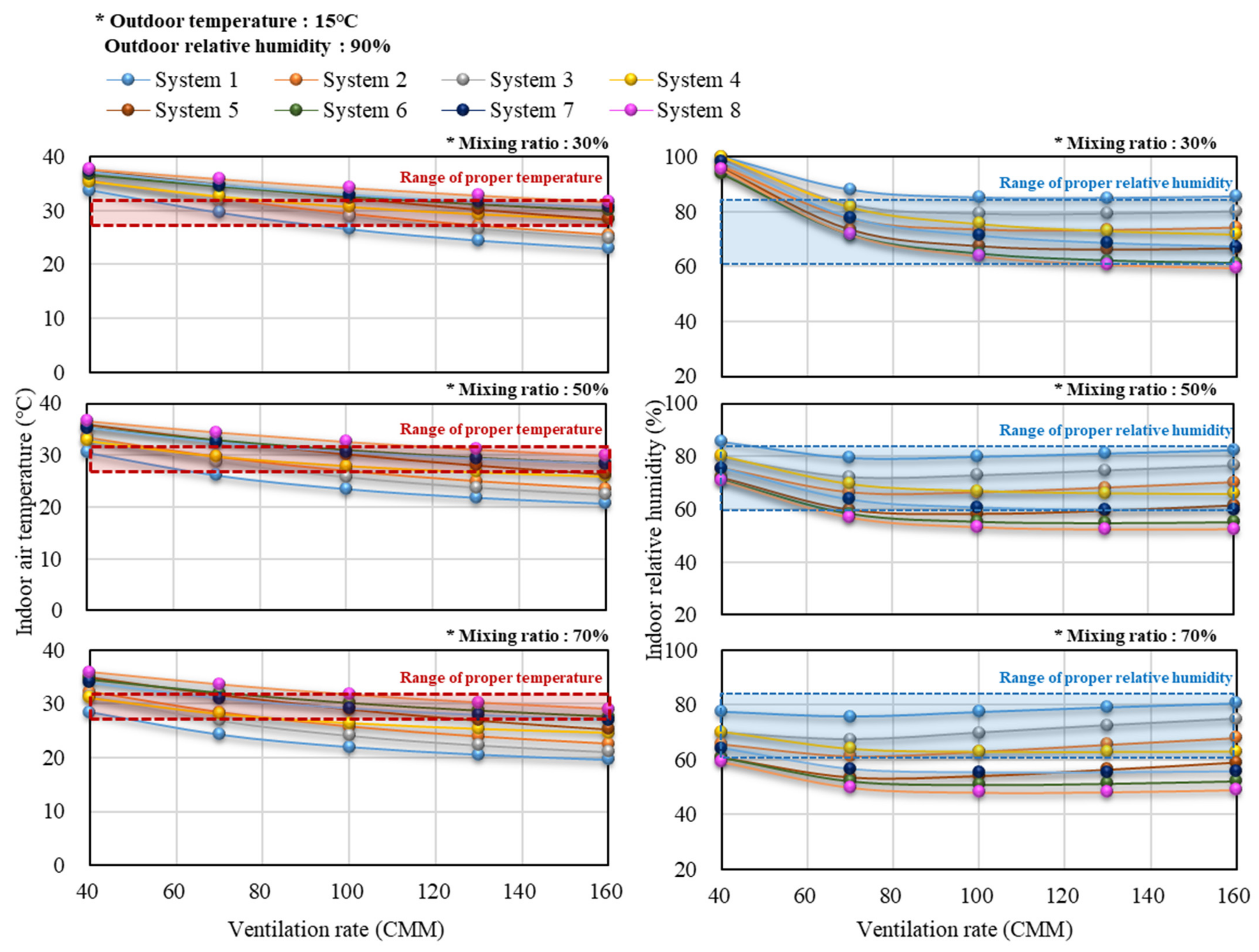
3.3. Air Temperature and Relative Humidity Results in the Experimental Piglet Room with the ARVS Applied

When the ARVS was applied according to the calculation conditions, the computed results of the internal environment are shown in Table. 6. In this study, among a total of 10,800 cases, the results of the summer season (outdoor temperature of 35 °C), the winter season (outdoor temperature of −5 °C), and the mild season (outdoor temperature of 15 °C) were selected as representative results (Table 6). The fixed values of the numerical model were the relative humidity of 90% and the ventilation rate of 160, 100, and 70 CMM. Although it is recommended as a minimum ventilation rate (20 CMM) in the winter season, this was an unacceptable condition that did not improve the gas environment, so it was excluded from the analysis results. The optimum temperature range was assumed to be 28–32 °C, and the optimum humidity range was assumed to be 60–85% [25].
In the summer season, when the outdoor temperature was 35 °C, the air temperature inside the piglet room was very high regardless of the configuration of the ARVS module. Because the outdoor air temperature was very high, the air temperature blown by the ventilation system remained at 35 °C, which resulted in difficulties in lowering the internal temperature to an appropriate level. It was impossible to lower the temperature without a cooler because the inside of the piglet room was heated by the heat production of the piglets. The effect of reducing the air temperature by the recirculation of water was considered. However, the air temperature was increased due to the internal heat generation, resulting in an average temperature inside the piglet room of 2 °C higher than the inflow air temperature. The wall heat transfer in the numerical model can be calculated according to the internal and external temperature difference, wall thickness, and thermal conductivity (wall characteristics). In the case of summer with a high ventilation rate, heat exchange has the greatest effect on the ventilation rate than the wall heat transfer. Accordingly, in summer, as the mixing ratio of external air at 35 °C was lower than the internal temperature, the air temperature inside the piglet room decreased. Compared with system 1 using only the wet scrubber module, the overall higher temperature was maintained in the systems using other modules. When the internal temperature in summer was lower than the external temperature, the inflow temperature was reduced in combinations such as systems 2 and 3 using a heat exchanger. However, because the actual temperature inside the piglet room was simulated higher, the use of the heat exchanger increased the temperature. Therefore, it is considered that the combination of a heat exchanger and solar heat was not suitable in summer. The method is required to lower the internal temperature by operating the cooling device or by frequently replacing the recirculation water to keep the water temperature low. In Korea, the hot season occurs from June to August, and the number of days when the external temperature exceeds 35 °C is less than 10 days. Therefore, it is advantageous to maintain the maximum ventilation rate and to increase the external air mixing ratio as much as possible when using the ARVS in the hot season. If the internal temperature is lower than the external air, it may be more advantageous to lower the temperature of the incoming air through the heat exchanger than to increase the external air mixing ratio.
On the other hand, in South Korea, relative humidity is often high during the rainy season. When the relative humidity of the external air in the hot season was 90%, the internal relative humidity was all simulated in a humid state. In the piglet room, moisture may be continuously generated inside the piglet room due to the piglet’s respiration and evaporation of moisture from the manure. In this case, since there was no device to remove moisture, moisture should be managed through sensible heat change in air condition. It can be suitable to drop the saturated water vapor pressure by generating condensed water through cooling and dehumidification.
When the external temperature is 15 °C, it was possible to maintain the proper temperature inside the piglet room even if only one module was added along with the basic module, including the wet scrubber module. Figure 9 illustrates the graph showing the results according to the ventilation rate and external air mixing ratio. In the case of system 1, when the air passed through the wet scrubber module and mixed with external air, it was mixed with air at 15 °C, so the temperature of the incoming air was low. In particular, when the mixing ratio was low, it was possible to properly maintain the internal temperature of the piglet room. However, when the ventilation rate was maintained above 100 CMM, it became below the appropriate temperature range. In addition, as the mixing ratio of external air increased, it became less than the appropriate temperature range in most combinations of modules. As shown in Table 3, when the mixing ratio was increased to 90%, it was simulated that the internal temperature was lowered to 21 °C when operating at a 70 CMM ventilation rate. The higher the external air mixing ratio, the greater the amount of discharging the thermal energy inside the piglet room to the outdoor. In the case of systems 2, 3, and 4, since internal heat energy was reused through the heat exchanger, an appropriate temperature could be maintained inside the piglet room even when the mixing ratio of external air was increased. In addition, systems 5, 6, 7, and 8 were also found to be able to sufficiently maintain the proper temperature inside the piglet room by controlling the mixing ratio of external air. In particular, during the mild weather condition, the relative humidity inside the piglet room can also be maintained properly. Therefore, it was analyzed that the system in which modules such as a heat exchanger and solar heat module were added could maintain the internal thermal environment properly by controlling the ventilation rate and external air mixing ratio according to the external air conditions.
In the case of system 1, which used only the wet scrubber module, the temperature inside the piglet room decreased rapidly as the external air mixing ratio increased during the cold season when the external temperature was −5 °C (Figure 10). When the external air mixing ratio was set to 10%, the temperature inside the piglet room converged to a proper condition because the inflow of low-temperature air was minimized. However, when the mixing ratio was maintained at 30% or more, the temperature inside the piglet room was low, resulting in low-temperature stress. In systems 2, 3, and 4, the internal temperature converged at about 33.4, 34.2, and 34.2 °C when the mixing ratio was 10%. However, since it was necessary to increase the external air mixing ratio to improve the gas environment, it was difficult to maintain the proper temperature in systems 2, 3, and 4 that add a single module. On the other hand, when two or more modules were used together with the wet scrubber module as in systems 5, 6, 7, and 8, the temperature increased about 5 °C when the mixing ratio was low, but it increased to 19.4 °C when the mixing ratio was high. In particular, in the case of system 8, which used all three modules, it was confirmed that the temperature inside the piglet room was maintained properly even if the mixing ratio was increased to 50%. Among systems 2, 3, 6, and 7 with different heat exchanger installation arrangements, the temperature inside the piglet room of systems 2 and 7 was about 1.2 °C higher. Therefore, when only one heat exchanger module was used, it was advantageous to install the heat exchanger after the wet scrubber module. The reason for this was to not lose thermal energy from the recirculation water while passing through the wet scrubber module. It was desirable to apply two or more ARVS modules together with the wet scrubber module to improve the temperature inside the piglet room during the cold season. In addition, in the case of using two modules in a system combination, the system 7 combination was most advantageous. When the mixing ratio of the external air had to be increased to improve the internal gas environment, the air temperature inside the piglet room could be decreased. Therefore, in consideration of the internal temperature, the external air mixing ratio should be controlled in real-time so that the internal gas environment can be properly maintained at the same time. Even if the relative humidity of the external air in winter was high, since the temperature could rise due to heat exchange, the saturated vapor pressure of the air increased. Accordingly, the relative humidity was lowered, and the internal moisture environment could be properly maintained. In addition, if the inside of the pig house is in a dry state, there is the advantage that humidification is possible with a wet scrubber module. Therefore, it is possible to properly maintain the moist environment inside the piglet room in winter through the ARVS.

3.4. Example of Optimal Operation for ARVS

In this study, using the numerical model of the ARVS, the internal thermal environment, moisture environment, and gas environment were simulated according to module combination, ventilation rate, and external air mixing ratio. When operating the ARVS, the internal temperature, humidity, and gas conditions can all be different depending on the module combination and external weather conditions. Therefore, it is necessary to determine the ventilation rate and external air mixing ratio to maintain an appropriate temperature, humidity, and gas environment according to the system combinations and external weather conditions. The ventilation rate and external air mixing ratio were determined to maintain the appropriate concentration of ammonia and carbon dioxide gas inside the experimental piglet room. Assuming that the proper temperature is maintained inside the piglet room using this ventilation rate, the external air mixing ratio should be determined based on this ventilation rate. Since it is impossible to remove the carbon dioxide with the wet scrubber module, increasing the external air mixing ratio should be accompanied. Additionally, if the external air mixing ratio and ventilation rate are maintained, the relative humidity inside the piglet room can also be predicted using a numerical model. In this study, when the outdoor air temperature was −5 °C and the relative humidity was 90%, the optimal operation plan for the ARVS (system 1 and system 7) was analyzed (Figure 11).
For example, when system 1 was installed, it was confirmed that the ventilation rate of 70 CMM or more should be operated to maintain the proper gas environment. When the ventilation rate was 70 CMM, the external air mixing ratio should be set to 12% to maintain the air temperature inside the piglet room at 30 °C, as shown in the left chart of Figure 11. The relative humidity inside the piglet room was 99% with this operating condition. If system 1 is installed and the ventilation rate is maintained at 130 CMM, even if the external air mixing ratio is controlled, the air temperature inside the piglet room cannot be maintained at 30 °C. On the other hand, when system 7 was installed, the external air mixing ratio should be set to 32% with the ventilation rate at 70 CMM to maintain the air temperature inside the piglet room at 30 °C. Because system 7 uses the heat exchanger and solar module, it can use more external air than system 1. Therefore, it was determined that system 7, which can use more external air, will be easier to control the gas environment, even if the same temperature is maintained. In addition, if system 7 is operated with this condition, the relative humidity inside the piglet room will be 66%. If system 7 is installed and the ventilation rate is 130 CMM, the external air mixing ratio should be set to 25% to maintain the air temperature inside the piglet room properly. The relative humidity inside the piglet room will be 70% under this condition.
In this way, it is possible to calculate the ventilation rate and external air mixing ratio to properly maintain the air temperature, relative humidity, and gas environment inside the piglet room, depending on the module combination of the target facility. In addition, the numerical model developed in this study can be used according to the external weather conditions to determine the necessary module combination and operation conditions when installing the ARVS.

4. Conclusions

In this study, an optimal numerical model for predicting the internal growth environment of the piglet house was developed to suggest a design and operation plan for the ARVS. This numerical model was designed based on various balance equations, and the environment inside the piglet room was calculated according to the heat, moisture, and gas generation mechanisms of the ARVS. Therefore, the developed numerical model can be used generally through farm information such as farm size, breeding age, and weather conditions.
To validate the thermal environment of the developed numerical model, a field experiment was conducted at the experimental testbed where the ARVS and modules were installed. The uncertainty of the numerical model considering internal heat generation and heat loss was selected as a validation variable. Comparative validation was conducted with the thermal environment data of the experimental piglet room in AcSEC-A3EL. Heat transfer with uncertainty was infiltration caused by infiltration, and the airflow can decrease due to the fan load. As a result of considering a 20% reduction in ventilation fan load and 1% infiltration rate in the numerical model, MBE and RMSE with air temperature data inside the experimental piglet room were calculated to be 0.23% and 0.11, respectively. In the case of additional modules, the removal efficiency, heat exchange efficiency, and solar thermal efficiency for each module were considered based on the field experiment data. For a new module, various conditions can be considered if the numerical model is modified through additional experiments.
As a result of calculating the numerical model, the ventilation rate of 40 CMM or more was advantageous to properly maintaining the gas environment. Additionally, when operated with a ventilation rate of 70 CMM or more, the external air mixing ratio could be sufficiently lowered. On the other hand, in the case of ammonia gas, it was removed by the wet scrubber module. Still, in the case of carbon dioxide, it was necessary to maintain the external air mixing ratio over a certain amount because the carbon dioxide cannot be removed using a wet scrubber module.
In the case of system 1 using a single module, the air temperature was higher than that using other modules in the summer season. In addition, in the case of systems 2 and 3 using the heat exchanger module, the proper air temperature could not be maintained because the air temperature of the inlet was increased. Therefore, it was necessary to additionally use the cooling device during the hot season. In the case of the external weather condition with high relative humidity, all of the internal relative humidity was simulated in an over-humid state, so the reduction of moisture content through a refrigeration dehumidifier was necessary. When the external air temperature was 15 °C, if the external air mixing ratio was increased by 50% or more, the internal air temperature was lowered to an appropriate level. The system using the heat exchanger and solar module could effectively use the internal thermal energy of the piglet room and maintain the air temperature properly. In the winter season, low-temperature stress could occur inside the piglet room when using system 1, except when the external air mixing ratio was 10%. When using a heat exchanger and solar module, the external air mixing ratio could be increased up to 50%. It was advantageous to use a heat exchanger and solar module at the same time. In particular, in systems 2, 3, 6, and 7 with different heat exchanger combination, system 3 and 7, in which the heat exchanger was installed after the wet scrubber module, was more advantageous for maintaining air temperature in the winter season.
From these results, the operation plan of the ARVS can be suggested using this numerical model. Based on the optimal design of this study, a scaled-up experiment and application of the ARVS will be conducted.

Author Contributions

Conceptualization, J.-g.K. and I.-b.L.; Data curation, J.-g.K.; Methodology, J.-g.K. and R.-w.K.; Software, J.-g.K. and A.A.; Supervision, I.-b.L.; Visualization, J.-g.K. and S.-y.L.; Writing—original draft, J.-g.K.; Writing—review and editing, I.-b.L., R.-w.K., S.-y.L., Y.-b.C., D.-y.J. and J.-h.C.; All authors have read and agreed to the published version of the manuscript.

Funding

This work was supported by the Institute of Information & communications Technology Planning & Evaluation (IITP) grant funded by the Korean government (MSIT). [IITP-2018-0-00387, Development of ICT-based Intelligent Smart Welfare Housing System for the Prevention and Control of Livestock Disease].

Institutional Review Board Statement

Not applicable.

Informed Consent Statement

Not applicable.

Data Availability Statement

All data will be made available on request to the correspondent author’s email with appropriate justification.

Conflicts of Interest

The authors declare no conflict of interest.

References

  1. Ministry of Agriculture Food and Rural Affairs. 2020. Available online: www.mafra.go.kr (accessed on 8 July 2020).
  2. Bai, X.; Plastow, G.S. Breeding for disease resilience: Opportunities to manage polymicrobial challenge and improve commercial performance in the pig industry. CABI Agric. Biosci. 2022, 3, 6. [Google Scholar] [CrossRef] [PubMed]
  3. Yeo, U.-H.; Decano-Valentin, C.; Ha, T.; Lee, I.-B.; Kim, R.-W.; Lee, S.-Y.; Kim, J.-G. Impact analysis of environmental conditions on odour dispersion emitted from pig house with complex terrain using CFD. Agronomy 2020, 10, 1828. [Google Scholar] [CrossRef]
  4. Kim, J.G.; Lee, I.B.; Lee, S.Y.; Park, S.J.; Jeong, D.Y.; Choi, Y.B.; Decano-Valentin, C.; Yeo, U.H. Development of an Air-Recirculated Ventilation System for a Piglet House, Part 1: Analysis of Representative Problems through Field Experiment and Aerodynamic Analysis Using CFD Simulation for Evaluating Applicability of System. Agriculture 2022, 12, 1139. [Google Scholar] [CrossRef]
  5. Pexas, G.; Mackenzie, S.G.; Wallace, M.; Kyriazakis, I. Cost-effectiveness of environmental impact abatement measures in a European pig production system. Agric. Syst. 2020, 182, 102843. [Google Scholar] [CrossRef]
  6. McMichael, A.J.; Powles, J.W.; Butler, C.D.; Uauy, R. Food, livestock production, energy, climate change, and health. Lancet 2007, 370, 1253–1263. [Google Scholar] [CrossRef]
  7. Racewicz, P.; Ludwiczak, A.; Skrzypczak, E.; Składanowska-Baryza, J.; Biesiada, H.; Nowak, T.; Nowaczewski, S.; Zaborowicz, M.; Stanisz, M.; Ślósarz, P. Welfare health and productivity in commercial pig herds. Animals 2021, 11, 1176. [Google Scholar] [CrossRef] [PubMed]
  8. Besant, R.W.; Simonson, C.J. Air-to-air energy recovery. ASHRAE J. 2000, 42, 31–43. [Google Scholar]
  9. Burton, D.J. Air recirculation: A case study. Occup. Health Saf. 2004, 73, 28–30. [Google Scholar]
  10. Ekinci, K.; Keener, H.; Akbolat, D. Effects of feedstock, airflow rate, and recirculation ratio on performance of composting systems with air recirculation. Bioresour. Technol. 2006, 97, 922–932. [Google Scholar] [CrossRef] [PubMed]
  11. Hall, A.; Saindon, J.; Nel, L.; Hardcastle, S. Feasibility of controlled recirculation of exhaust air to reduce heating costs at Ruttan Mine, Manitoba. In Proceedings of the CIM BULLETIN, Edmonton, AB, Canada, 4–6 June 1987; p. 89. [Google Scholar]
  12. Park, S.; Seo, J. Analysis of Air-side economizers in terms of cooling-energy performance in a data center considering Exhaust air recirculation. Energies 2018, 11, 444. [Google Scholar] [CrossRef]
  13. Ziegler, T.; Jubaer, H.; Schütz, M. Increasing the Energy Efficiency of Batch-Type Drying with Partial Air Recirculation. Chem. Ing. Tech. 2016, 88, 208–214. [Google Scholar] [CrossRef]
  14. American National Standards Institute (ANSI). 2007. Available online: websotre.ansi.org (accessed on 8 July 2020).
  15. Donham, K.J. Association of environmental air contaminants with disease and productivity in swine. Am. J. Vet. Res. 1991, 52, 1723–1730. [Google Scholar] [PubMed]
  16. Alvarado, A.C.; Predicala, B.Z. Control of Gas and Odor Levels in Swine Facilities Using Filters with Zinc Oxide Nanoparticles. Trans. ASABE 2017, 60, 943–956. [Google Scholar] [CrossRef]
  17. Anthony, T.R.; Altmaier, R.; Jones, S.; Gassman, R.; Park, J.H.; Peters, T.M. Use of recirculating ventilation with dust filtration to improve wintertime air quality in a swine farrowing room. J. Occup. Environ. Hyg. 2015, 12, 635–646. [Google Scholar] [CrossRef] [PubMed]
  18. Anthony, T.R.; Altmaier, R.; Park, J.H.; Peters, T.M. Modeled effectiveness of ventilation with contaminant control devices on indoor air quality in a swine farrowing facility. J. Occup. Environ. Hyg. 2014, 11, 434–449. [Google Scholar] [CrossRef]
  19. Anthony, T.R.; Yang, A.Y.; Peters, T.M. Assessment of interventions to improve air quality in a livestock building. J. Agric. Saf. Health 2017, 23, 247–263. [Google Scholar] [CrossRef]
  20. Park, J.H.; Peters, T.M.; Altmaier, R.; Jones, S.M.; Gassman, R.; Anthony, T.R. Simulation of air quality and operating cost to ventilate swine farrowing facilities in the midwest US during winter. Trans. ASABE 2017, 60, 465–477. [Google Scholar]
  21. Lau, A.; Vizcarra, A.; Lo, K.; Luymes, J. Recirculation of filtered air in pig barns. Can. Agric. Eng. 1996, 38, 297–304. [Google Scholar]
  22. Wenke, C.; Pospiech, J.; Reutter, T.; Altmann, B.; Truyen, U.; Speck, S. Impact of different supply air and recirculating air filtration systems on stable climate, animal health, and performance of fattening pigs in a commercial pig farm. PLoS ONE 2018, 13, e0194641. [Google Scholar] [CrossRef]
  23. Peters, T.M.; Sawvel, R.A.; Park, J.H.; Anthony, T.R. Evaluation of a shaker dust collector for use in a recirculating ventilation system. J. Occup. Environ. Hyg. 2015, 12, D201–D210. [Google Scholar] [CrossRef]
  24. Mostafa, E.; Hoelscher, R.; Diekmann, B.; Ghaly, A.; Buescher, W. Evaluation of two indoor air pollution abatement techniques in forced-ventilation fattening pig barns. Atmos. Pollut. Res. 2017, 8, 428–438. [Google Scholar] [CrossRef]
  25. Ministry of Agriculture Food and Rural Affairs. 2006. Available online: www.mafra.go.kr (accessed on 8 July 2020).
  26. CIGR. Heat and Moisture Production at Animal and House Levels; International Commission of Agricultural and Biosystems Engineerin: Liège, Belgium, 2002; pp. 37–40. [Google Scholar]
  27. ASHRAE. American Society of Heating and Air-Conditioning Engineers; ASHRAE: New York, NY, USA, 2017. [Google Scholar]
  28. Hayes, M.D.; Brown-Brandl, T.M.; Stinn, J.P.; Li, H.; Xin, H.; Nienaber, J.A.; Shepherd, T.A. House-level moisture production of modern swine by age, temperature and source. In Proceedings of Transactions of the ASABE (American Society of Agricultural and Biological Engineers), Kansas City, MO, USA, 21–24 July 2013; ASABE: Joseph, MI, USA, 2013; p. 1. [Google Scholar]
  29. National Institute of Environmental Research. 2013. Available online: www.nier.go.kr (accessed on 8 July 2020).
  30. Van Ouwerkerk, E.; Pedersen, S. Application of the carbon dioxide mass balance method to evaluate ventilation rates in livestock buildings. In Proceedings of the XII CIGR World Congress on Agricultural Engineering, Milan, Italy, 29 August–1 September 1994; pp. 516–529. [Google Scholar]
  31. Nam, S. Agricultural Facility Engineering; Korea Academy Publishing Association: Seoul, Korea, 2018. [Google Scholar]
  32. Zhao, Y.; Aarnink, A.; De Jong, M.; Ogink, N.; Koerkamp, P.G. Effectiveness of multi-stage scrubbers in reducing emissions of air pollutants from pig houses. Trans. ASABE 2011, 54, 285–293. [Google Scholar] [CrossRef]
  33. Hundy, G. Refrigeration, Air Conditioning and Heat Pumps; Butterworth-Heinemann: Oxford, UK, 2016. [Google Scholar]
  34. Midwest Plan Service. Swine Housing and Equipment Handbook; Midwest Plan Service: Ames, IA, USA, 1983. [Google Scholar]
Figure 1. Schematic diagram of the conventional ventilation system and the developed ARVS. The conventional ventilation system (a) uses external air directly and exhausts internal air. The ARVS (b) reuse the internal air for ventilation.
Agriculture 12 01533 g001
Figure 2. Flow chart for a numerical model of air recirculated ventilation system.
Agriculture 12 01533 g002
Figure 3. Schematic view of target piglet house at Artificially controlled Smartfarm Engineering Center of Aero-Environmental and Energy Engineering Laboratory (AcSEC-A3EL), Seoul National University, Korea.
Agriculture 12 01533 g003
Figure 4. Measurement of air temperature for validation of the numerical design of ARVS.
Agriculture 12 01533 g004
Figure 5. Schematic diagram of the air recirculated ventilation system. (1) Heat exchanger can reuse the internal heat of pig house according to the exchange efficiency. (2) it can reuse the heat after wet scrubber. (3) Solar heat exchanger was additional heating device to use solar energy.
Agriculture 12 01533 g005
Figure 6. Algorithm of the numerical design of the ARVS. At the stage (A), the boundary conditions of air can be set. After passing the air recirculation system, the air condition can be changed at stage (B). Finally, the output data (C) can be compared with the results of (A).
Agriculture 12 01533 g006
Figure 7. Thermal environment of the measured data and calculation data of the numerical model according to the ventilation rate and infiltration rate.
Agriculture 12 01533 g007
Figure 8. Computed results of the numerical model according to the ventilation rate and outdoor air mixing ratio.
Agriculture 12 01533 g008
Figure 9. The air temperature and relative humidity inside the experimental piglet room by ARVS according to the ventilation rate and the external air mixing ratio (external air temperature 15 °C, external air relative humidity 90%).
Agriculture 12 01533 g009
Figure 10. The air temperature and relative humidity inside the experimental piglet room by ARVS according to the ventilation rate and the external air mixing ratio (external air temperature −5 °C, external air relative humidity 90%).
Agriculture 12 01533 g010
Figure 11. Example of an optimal operation method for ARVS (System 1, System7).
Agriculture 12 01533 g011
Table 1. Heat production of the piglets inside the experimental piglet room [26].
ContentsValue
Heads of piglets174
Weight of each piglet (kg)15
Daily feed energy3.44
Total heat (kcal·h−1·head−1) (in 34.5 °C)79
Sensible heat (kcal·h−1·head−1) (in 34.5 °C)25
Latent heat (kcal·h−1·head−1) (in 34.5 °C)54
Table 2. The input value of boundary conditions in the numerical model for thermal environment validation.
Case 1Case 2Case 3Case 4Case 5Case 6
Infiltration rate (%)10511051
Ventilation rate (CMM)10080
Table 3. Summary of descriptive statistics used for the analysis.
Descriptive StatisticsAcronymsEquations
Mean Bias ErrorsMBE (%) MBE = t P t ¯ M t ¯ t M t ¯ × 100
Root Mean Square ErrorRMSE RMSE = 1 n t = 1 n P t M t 2
P t : Predicted valued at hour t. M t : Measured value at hour t.
Table 4. Total cases to determine optimal air recirculated ventilation system according to the combination of (1), (2), and (3) module.
Schematic Diagram of the ARVS
System 1Basic module
System 2Basic module + (1)
System 3Basic module + (2)
System 4Basic module + (3)
System 5Basic module + (1), (2)
System 6Basic module + (1), (3)
System 7Basic module + (2), (3)
System 8Basic module + (1), (2), (3)
Environmental condition
Outdoor air temperature (°C)−0, 0, 5, 10, 15, 20, 25, 30, 35
Outdoor air relative humidity (%)50, 60, 70, 80, 90, 100
Ventilation rate (CMM)40, 70, 100, 130, 160
Mixing ratio of outdoor air (%)10, 30, 50, 70, 90
Total cases
10,800
Table 5. Results of MBE and RMSE statistics of calculation results according to the ventilation rate and infiltration rate.
Case 1Case 2Case 3Case 4Case 5Case 6
MBE (%)9.386.598.152.451.290.23
RMSE3.192.782.250.830.440.11
Table 6. Computed results of internal air temperature and relative humidity of the piglet room with the ARVS according to the external conditions, ventilation rates, and mixing ratio of external air.
External Air Temperature
(°C)
External Relative Humidity
(%)
Ventilation Rate
(CMM)
Mixing Ratio of External Air
(%)
Air Condition Inside the Piglet Room
Temp
(°C)
RH
(%)
Temp
(°C)
RH
(%)
Temp
(°C)
RH
(%)
Temp
(°C)
RH
(%)
System 1System 2System 3System 4
35901601038.710039.110039.210039.2100
1603037.39837.89537.79638.095
1605036.59437.29136.89337.491
1607036.39237.08936.49137.188
1609036.29037.08736.39037.087
15901001034.510036.010036.510036.6100
1003026.68529.47328.97930.776
1005023.58027.06625.87328.067
1007022.07725.86324.17026.463
1009021.07625.06123.16825.361
−590701031.010033.410034.210034.2100
703018.58823.26824.17725.575
705012.27918.25718.16520.062
70708.87215.55214.45816.654
70906.76813.84812.05414.149
System 5System 6System 7System 8
35901601039.510039.410039.610039.6100
1603038.39438.49338.49438.792
1605037.68938.08837.79038.287
1607037.48737.88537.48737.985
1609037.28637.88337.28637.883
15901001037.710037.210037.910038.1100
1003032.36732.86533.07134.264
1005030.25831.05530.66132.653
1007029.05430.15129.25631.748
1009028.35229.64828.25231.145
−590701036.010035.310036.310036.6100
703029.56028.85730.36832.157
705025.64625.44326.35129.341
707023.13923.33723.54227.433
709021.43522.03321.43626.129
Publisher’s Note: MDPI stays neutral with regard to jurisdictional claims in published maps and institutional affiliations.

