Article

Control Strategy of Grain Truck Following Operation Considering Variable Loads and Control Delay

1
College of Mechanical and Electrical Engineering, Agricultural University of Hebei, Baoding 071001, China
2
Institute for the Smart Agriculture, Jilin Agricultural University, Jilin 130118, China
3
Beijing Research Center of Intelligent Equipment for Agriculture, Beijing 100097, China
*
Author to whom correspondence should be addressed.
Agriculture 2022, 12(10), 1545; https://doi.org/10.3390/agriculture12101545
Submission received: 1 September 2022 / Revised: 20 September 2022 / Accepted: 21 September 2022 / Published: 25 September 2022

Abstract

:
Considering the slow response and unstable velocity of agricultural machinery caused by soil resistance, actuator delay, environmental change, velocity fluctuation, and other internal and external factors under real working conditions, a kind of agricultural machinery following a control system that considers variable load and control delay was proposed. Taking distance-keeping, velocity-following, and acceleration-following as parameters, the controller model was deduced, and the influence of different values of model parameters on the driving stability of agricultural machinery was analyzed in detail. In addition, this paper describes a kind of agricultural machinery following a strategy that can realize the graded adjustment of vehicle distance with the dynamic increase in vehicle weight. Then, the following strategy, under the influence of velocity and quality, was simulated and verified using MATLAB/Simulink (MATLAB2016a, mathworks: Natick, Massachusetts, USA). When the crop harvester was at 1.5 m/s and the amplitude of velocity fluctuation was 0.3 m and 1.3 m, respectively, the grain truck could adjust its velocity to keep up with the crop harvester to complete the operation task. Simulation verification was carried out for the proposed graded adjustment of vehicle distance of agricultural machinery following strategy. The unit mass of the crops was set at 360 kg, and the vehicle distance changed at 18s to adapt to the graded adjustment of the vehicle distance following strategy. Finally, a real-vehicle validation test was carried out, and the results show that the grain truck velocity can keep up with the change of crop harvester velocity on the basis of maintaining the desired vehicle distance, the grain truck velocity can keep up with the change of crop harvester velocity on the road condition, which verifies the effectiveness and feasibility of the proposed method.

1. Introduction

At the beginning of the development of agricultural navigation technology, due to technical limitations, the mainstream of agricultural navigation technology is single-machine automatic navigation [1,2,3]. In recent years, relying on the leap-forward development of positioning and communication technology, the automatic navigation technology of agricultural machinery has significantly developed [4,5]. The current intensive, large-scale, industrialized, and unmanned agricultural production [6], put forward higher requirements for automatic navigation technology of agricultural machinery; therefore, multi-machine cooperative operation, which can effectively improve the efficiency and utilization rate of agricultural machinery, has gradually been paid attention to by agricultural researchers.
Multi-machine collaborative operation originated in the field of robotics and the automotive industry [7,8]; however, it is rarely used in agriculture. Research into a multi-machine collaboration of agricultural machinery can be traced back to the end of the 20th century. In 2000, Lidam et al. of Kyoto University in Japan developed an automatic following control system for agricultural vehicles. Each vehicle is equipped with ultrasonic sensors to measure the relative position and declination angle between vehicles [9]. Due to the limitation of infrared and ultrasonic equipment, the system signal is inevitably unstable during the steering process. In 2004, Noguchi N et al. of Hokkaido University proposed a cooperative operation system of agricultural machinery with two operation modes of “GOTO” and “FOLLOW” [10]. In the GOTO mode, the slave can receive the command sent by the host and complete the specified task according to the received command. The FOLLOW mode realizes the precise following operation of the following agricultural machinery to the leading agricultural machinery at a fixed distance and declination angle. It can be applied to the same kind of agricultural machinery operation, and can also be applied to the master–slave joint follow-up operation of crop harvesters and carriers, so the FOLLOW mode has more application value than the GOTO mode. After years of development, the research on the cooperative operation of agricultural machinery and multi-machines has a certain foundation. At present, a multi-machine cooperative operation is divided into two modes: follower cooperative operation and command-type master–slave cooperative operation [11].
Follow-up master–slave collaborative operation means that multiple agricultural machines work together in the field, using one of the agricultural machines as the master, and the other agricultural machines as slaves to follow the master. Researchers have undertaken a lot of research on follower master–slave collaborative work. Zhang et al. of Hokkaido University developed a leadership-following system based on two agricultural robots [12], which realizes that the two robots cooperate with each other to complete operations such as straight-traveling and follow-up, head-turning, and other operations on the basis of ensuring no collision. Zhang et al. of Karlsruhe Institute of Technology developed an intelligent master–slave system for agricultural vehicles [13], which enables the slave vehicle to follow the master vehicle at a given lateral and longitudinal offset, but the fixed-distance following strategy cannot be fully adapted to the complex and changeable working environment. Bai Xiaoping’s team combined the feedback linearization theory and the sliding mode control theory to design the control law for the formation of the combine harvester group and the control law for the path tracking, which realized the high-precision follow-up operation of the agricultural machinery [14,15]. Xu Guangfei designed a master–slave follower controller for tractors combined with the model predictive control algorithm [16]. On the basis of ensuring the master–slave follower of agricultural machinery, it can effectively deal with factors such as environmental uncertainty and interference. However, both SMC and MPC algorithms have a large computational burden and require high perform controllers, so it is currently difficult to apply them to real vehicle scenarios on a large scale. Lee uses the vision system to realize the forward synchronization of the two vehicles and uses the PID control system to control the steering but does not consider the control delay caused by the sensor delay [17]. Luo uses the master–slave cooperative control method and considers the response delay of the actuator to solve the problem that the two vehicles are not driving in the same straight line in the WSIC operation mode [18]. ZHU adopts the LQR controller to solve the problem of maintaining the lateral distance of the tractor queue and realizes the precise tracking of the straight path and the curved path of the tractor queue [19]. Vougioukas developed a distributed control framework for coordinating the movements of teams of autonomous agricultural vehicles operating in the same field [20].
Command-type master–slave collaborative operation means that the remote monitoring platform issues the overall task and commands each agricultural machine to go to a specific area to perform the task. Among them, in the representative GOTO mode [10], HAO et al. used two robots to verify a collaborative scheme between the harvester and the grain truck owner-slave indoors [21]. The harvester, as the leader, can decide the behavior of the grain truck; as a follower, the grain truck can adjust its position and heading according to the pilot’s instructions, and Martin et al. developed an order-based master–slave cooperative job path planning system, one slave using Dijkstra algorithm to plan the optimal path, providing collaboration service for two masters [22].
The above research has carried out in-depth research on the two operation modes of multi-machine cooperation, especially for the follow-up master–slave cooperative operation, and a variety of control methods have been proposed. Most of the above control algorithms do not introduce the sensor delay and cause the system to respond slowly; at the same time, the vehicle-following strategy basically adopts a fixed-distance vehicle-following strategy. When faced with application scenarios such as grain trucks following crop harvesters to unload grain, the vehicle distance cannot be adjusted in time to eliminate crop accumulation, which is obviously insufficient in flexibility. At the same time, the algorithm has high requirements on the computing power of the controller and uses too many devices, which is not conducive to large-scale popularization. Affected by the application scenarios of agricultural machinery and the educational level of users, the control system of intelligent agricultural machinery equipment must be simple in structure and easy to build and implement. In this paper, considering the dynamic change of the weight of the grain transport vehicle and the control delay, a dynamic distance following strategy of the grain transport vehicle combined with the traditional constant time headway policy is proposed, and a follow-up master–slave cooperative controller for the grain transport vehicle is designed based on the nonlinear feedback algorithm.

2. Grain Truck Controller Strategy

Under the autonomous farm operation circumstances [23,24,25,26], the grain truck automatically moves with the crop harvester and completes the storage and transfer operations, which is a common form of agricultural machinery collaborative operation [27,28], as shown in Figure 1a.

2.1. Crop Harvester and Grain Truck Follow-up Operation Model

In this paper, crop harvester and grain truck longitudinal straight line following operation as the research object, lateral control is not considered. The grain truck is the controlled object, and the crop harvester is the following target. The following diagram is shown in Figure 1b.
In Figure 1b, a fixed base station differential centimeter-level positioning system fused with inertial group information is used to provide centimeter-level positioning accuracy for the two vehicles. The mobile station installed at the center point of the front axle of the grain truck and crop harvester obtains its own position relative to the base station, heading angle, velocity, acceleration, and other information. The following distance of the vehicle is based on the relative distance of the positioning system. The grain truck obtains the positioning and driving information of the crop harvester through the workshop communication equipment. Δ x is the longitudinal distance between the grain truck and the crop harvester; Δ y is the lateral distance between the grain truck and the crop harvester;   XOY is the geodetic coordinate system of the main base station; x 1 o 1 y 1 is the body coordinate system of the grain truck; x 2 o 2 y 2 is the body coordinate system of the crop harvester; The x-axis of the body coordinate system points to the vehicle’s driving direction parallel to the ground, the y-axis of the coordinate system points to the left side of the vehicle body, and the z-axis of the coordinate system points to the top of the vehicle body through the center of mass of the agricultural machine, θ represents the heading angle of the agricultural machine in the geodetic coordinate system, the true north direction is zero degrees. The parameter’s geometric relationship can be obtained in Figure 1b.
Δ X d = X d 2 X d 1 Δ Y d = Y d 1 Y d 2
[ Δ x Δ y ] = [ sin θ cos θ cos θ sin θ ] [ Δ X d Δ Y d ]

2.2. Grain Truck Following Strategy

In this paper, the traditional constant time headway model is introduced to control the velocity of the grain truck and the distance relative to the crop harvester [29]. On this basis, to eliminate the accumulation of crops and so that the grain truck can adapt to the change of load weight load to adjust the distance, the quality parameter is introduced in the vehicle strategy, as in Equation (3).
{ d d = d 0 + t d v k INT [ M m ] k INT [ M m ] + 0 . 5 A
Where d d is the grain truck desired following distance; d 0 is the minimal following distance; t d is the time headway; v is the velocity of the grain truck; M is the grain mass from the harvester; m is the crops of unit mass set based on grain truck with different loads; k is the mass distance factor in meter; INT is the rounding functions; and A is the length of the grain truck.
Equation (3) can be transformed into a desired velocity function V ( h ) based on the current following distance h .
The advantage of the above following strategy is that, on the one hand, the grain truck can adjust the velocity based on the relative distance from the crop harvester in real time; on the other hand, the grain truck’s desired following distance can be adjusted by the load of the vehicle, the position of the grain transport carriage is adjusted in an orderly manner to avoid single point accumulation of crops in the grain transport carriage, thereby improving the utilization rate of the carriage. The initial position of the output port of the crop harvester is located at the front of the grain truck. When the velocity of the grain truck decreases, the following distance between the grain truck and the crop harvester increases, and the position of the discharge port moves to the front of the grain truck, causing crops to spray out of the carriage. To avoid the above situation in the initial position or end position. The maximum adjustment distance between the outlet and the compartment is less than the length of the grain truck compartment 0.5m.

3. Design of Follower Controller for Grain Truck

In this paper, the velocity controller of the grain truck is designed by combining the following strategy, velocity error, crop harvester acceleration, and system delay, such as in Equation (4). At the same time, the controller introduces an integral term to eliminate the response error caused by soil resistance and soil softness. Generally, the system delay is caused by the wireless communication cycle, the main program control cycle, and the action response of the actuator.
[ v ˙ 0 ( t ) e ˙ ( t ) h ˙ 1 , 0 ( t ) ] = [ Z p e ˙ ( t τ ) + Z i e ( t τ ) + Z v h ˙ 1 , 0 ( t τ ) + Z a v ˙ 1 ( t τ ) V ( h 1 , 0 ( t ) ) v 0 ( t ) v 1 ( t ) v 0 ( t ) ]
v ˙ 0 ( t ) is the acceleration of the grain truck; h ˙ 1 , 0 ( t ) is the grain truck and harvester relative velocity; v ˙ 1 ( t τ ) is the harvester velocity without controller delay; e ˙ ( t ) is the error of the grain truck desire and actual velocity; e is the grain truck following distance error; h 1 , 0 ( t ) is the current distance of the harvester and grain truck; Z p , Z i , Z v , Z a is the gain coefficients.
The dots above the symbols represent the differentiation with respect to time.
When the crop harvester is operating at a constant velocity, it is driving at a constant speed v c and distance h c with the grain truck. When the crop harvester velocity changes actively or passively, it can be seen as velocity fluctuation based on a constant velocity, the fluctuation amount is set as
v ˜ 1 ( t ) = v 1 ( t ) v c       h ˜ 1 , 0 = h 1 , 0 ( t ) h c
The following distance error of the grain truck is obviously also affected.
e c is the following distance error when the grain truck operates at a constant velocity;
e ˜ ( t ) = e ( t ) e c
Since the grain truck changes with the crop harvester, the grain truck will also fluctuate. Substituting Equations (5) and (6) into Equation (4), the new fluctuation model is obtained.
[ v ˜ ˙ 0 ( t ) e ˜ ˙ ( t ) h ˜ ˙ 1 , 0 ( t ) ] = [ Z p e ˜ ˙ ( t τ ) + Z i e ˜ ( t τ ) + Z v h ˜ ˙ 1 , 0 ( t τ ) + Z a v ˜ ˙ 1 ( t τ ) f h ˜ 1 , 0 ( t ) v ˜ 0 ( t ) v ˜ 1 ( t ) v ˜ 0 ( t ) ]
Here f = 1 / t d , there will be velocity fluctuations when the agricultural machinery operating. Taking the velocity fluctuation of the crop harvester as the input quantity and the velocity fluctuation of the grain truck as the output quantity, performing Laplace transform on the Equation (7) under the zero initial condition, and obtaining the Equation (8).
G 0 , 1 ( s ) = V ˜ 0 ( s ) V ˜ 1 ( s ) = Z v s 2 + Z p f s + f Z i + Z a s 3 s 3 e τ s + ( Z p + Z v ) s 2 + ( f Z p + Z i ) s + f Z i

4. Stability Analysis of Following System for Grain Truck and Crop Harvester

The necessary and sufficient conditions for the following stability of grain trucks and crop harvesters are
| G 0 , 1 ( i w ) | < 1     w > 0
The velocity fluctuation of the crop harvester will be reduced when it is transmitted to the grain truck. It is obvious to see from Equation (9) that there is a special fluctuation frequency that
{ | G 0 , 1 ( i w 1 ) | = 1 | G 0 , 1 ( i w 1 ) | = 0 | G 0 , 1 ( i w 1 ) | < 0
w 1 is the maximum critical frequency. From the Equation (10), the stability region of the following system of the grain truck can be obtained.
To simplify the operation, use the equivalent form of Equation (9)
T ( w ) = | G 0 , 1 ( i w ) | 2 < 1
Substituting Equation (8) into Equation (11), deforming Equation (12)
T ( w ) = a 1 w 6 + a 2 w 5 a 3 w 4 + a 4 w 3 + a 5 w 2 Z i 2 2 f Z i 2 f 2 Z p 2 2 f 2 Z p Z i 2 f Z p Z i
In the Equation
a 1 = Z a 2 cos 2 ( τ ω ) sin 2 ( τ ω )
a 2 = 2 Z p sin ( τ ω ) + 2 Z v sin ( τ ω )
a 3 = 2 Z p Z v + Z p 2 + 2 f Z p Z a
a 4 = 2 f Z i sin ( τ ω ) 2 f Z p sin ( τ ω ) 2 Z i sin ( τ ω )
a 5 = 2 Z p Z i + 2 Z i Z v + 2 f Z p 2 + f 2 Z p 2 + 2 f Z p Z i + 2 f Z p Z v
If Equation (12) reaches its maximum value when w 1 = 0, Equation (12) can be simplified to
T ( w 1 ) = Z i 2 2 f Z i 2 f 2 Z p 2 2 f 2 Z p Z i 2 f Z p Z i
From Equation (11) and Equation (13), the parameters must be Z p > 0 and Z i > 0 .
Set the parameters Z i and Z a as 0.2 and 0.25, respectively, and take the delay time as 0.2 s. According to Equation (8), (10) and (11), draw the stability region of the multi-machine following system of agricultural machinery, as shown in Figure 2a. This area is delineated by blue dots, and the parameters in this area satisfy the stability condition of the system.
Three parameters are selected from Figure 2a to plot the stability, as shown in Figure 2b. Point A is selected from the interior of the stability interval, point B is selected from the boundary of the stability area, and point C is selected from the outside of the stability area.
Comparing the three points A, B, and C, it can be seen from Figure 2b that the magnitude of the two points A and B are always less than or equal to 0, which matches the multi-machine driving stability conditions of agricultural machinery. The velocity fluctuation of any frequency of the crop harvester will be reduced during the transfer to the grain truck. The magnitude of point C is greater than 0, and the system is unstable during high-frequency fluctuations. From the above analysis, it can be proved that the drawn stability reference area map meets the multi-machine driving stability requirements.
In order to analyze the influence of different delay parameters on the stability region, assume Z i = 0.4 , Z a = 0.6 , and draw the stability region, as shown in Figure 3.
From the analysis of Figure 3, it can be seen that the influence of delay parameters on stability is as follows: the longer the delay time, the smaller the stability interval. The calculation period of the controller algorithm is 20 ms, the signal of the positioning system is delayed by 50 ms, the response delay of the hardware controller of the grain truck is 50 ms, and the time delay of the whole system is approximately 0.15 s, which meets the system stability requirements.
Set the relevant parameters Z i = 0.4 , τ = 0.15 , other parameters remain unchanged, adjust the value of Z a and draw a part of the stability area as shown in Figure 4. It is found that with the increase of Z a value, the stability range first increases and then decreases. This shows that a suitable Z a will increase the stability parameter selection range of the system, and if the value is too large, the range of the system stability region will be reduced. The stable range is greatest when Z a is close to 0.4.
In order to verify the influence of a single variable on the system stability region, Za = 0.6, τ = 0.15 are remained, and Zi is taken as 0.1, 1, and 1.9, while the other parameters remain unchanged, and the range of part of the stability region is drawn as shown in Figure 5.
It can be seen from Figure 5 that as the value of Z i increases, the stability region shows a trend of gradually shrinking, and when Z i is close to 0.1, the stability region is the largest, and the selection range of other parameters is wider at this time. Similar analysis above is carried out on Z p and Z v , and the range of parameter selection parameters satisfying the following stability of agricultural machinery can be obtained. As the value of Z p increases, the stability region first increases and then decreases, and the stability region of Z p is the largest around 0.7; while the value of Z v is between 0 and 1, the stability region is the largest and does not change significantly, and after 1 The stability region gradually decreases. In summary, after determining the values of some parameters, the optimal interval of other parameters can be obtained to ensure the stability of the system.

5. Simulation and Vehicle Testing

5.1. Simulation Analysis

In order to verify the feasibility of the algorithm, a simulation operation scene is built, the crop harvester is in the front, and the grain truck is in the back. According to the previous stability analysis results, the simulation settings are Z p = 0.6 , Z i = 0.2 , Z v = 0.7 , Z a = 0.3 , τ = 0.15 , k = 0 . The two vehicles initially maintain a constant velocity balance, the velocity is 1 m/s, and the velocity of the crop harvester jumps to 2 m/s at 15 s. The simulation results are shown in Figure 6a, the grain truck catches the harvester’s velocity at time 25 s, achieving new velocity balance. In order to further verify the response time of velocity fluctuations, the adjusted Z p values were selected to be 0.2 and 1, and the response time of the velocity change of the grain truck was observed. The results are shown in Figure 6b,c, respectively. A new dynamic balance is reached at 35 s and 28 s. It can be seen from the results in Figure 6 that the algorithm proposed in this paper can realize the controlled vehicle to follow the driving stably, and at the same time, by adjusting the size of the control parameters, the response time of the velocity change can be changed. It can be seen from the following distance error diagram in Figure 6 that the expected vehicle distance error of the crop harvester can converge to 0 after the velocity step change, so it can be seen that the algorithm in this paper can effectively follow the expected vehicle distance change caused by the velocity change.
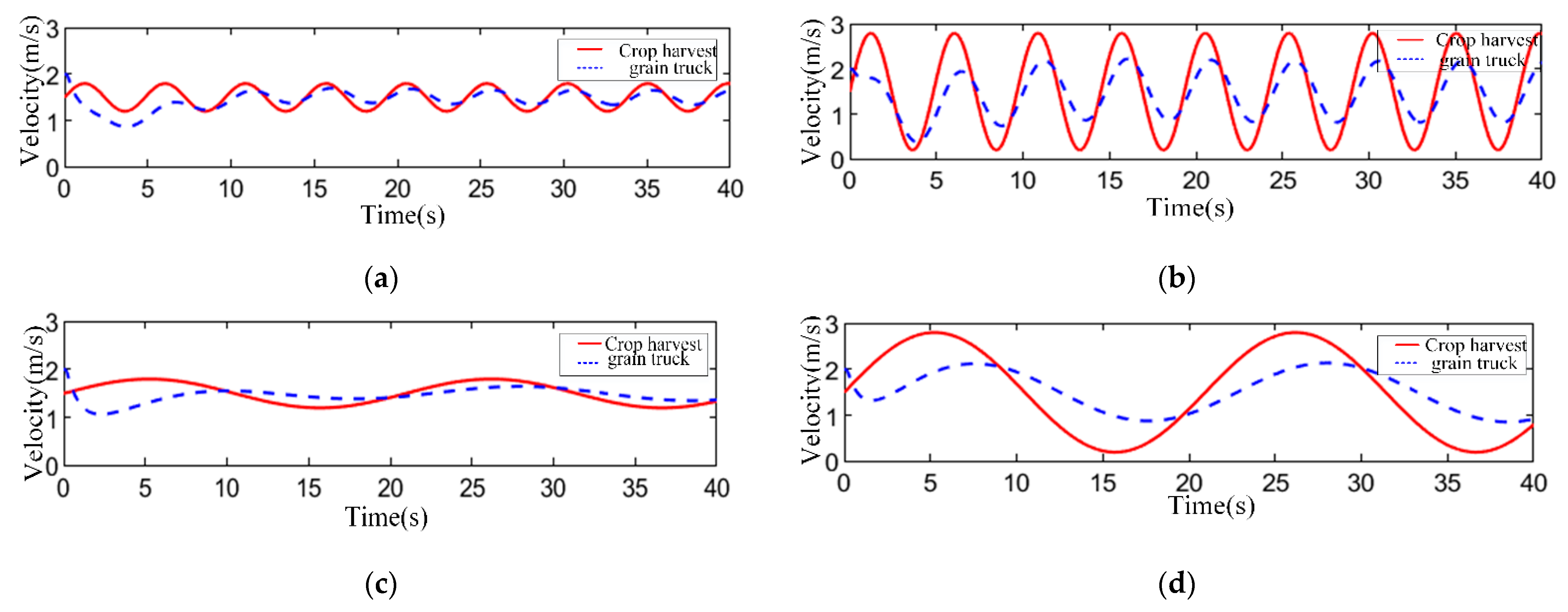
In order to verify that the algorithm also has good following performance under continuous velocity disturbances, the parameter Z p = 0.6 is set, and velocity disturbances of different frequencies and magnitudes are applied to the crop harvester, respectively. The other control parameters are as above. The simulation is consistent, and the simulation results are shown in Figure 7. Figure 7a,b are high-frequency high-magnitude velocity and high-frequency low-magnitude velocity diagrams. It can be seen from the two figures that in the face of high-frequency velocity disturbance, the grain truck adjusts the velocity within a certain period of time. It can keep the same frequency change with the crop harvester, and for the velocity fluctuations of different magnitudes, the algorithm can ensure that the crop harvester can achieve stable follow-up status. Figure 7c,d are the low-frequency velocity diagrams with different magnitude, which can be obtained from the figure. Grain trucks can also achieve a stable following. Analysis of the above shows that the algorithm has strong resistance to velocity disturbance, and the high-amplitude and high-frequency velocity disturbance of the crop harvester does not affect the normal operation of the grain truck. At the same time, it is observed that the velocity fluctuation of the grain truck in the image is smaller than the velocity fluctuation of the crop harvester, which is in line with the stability condition of multi-vehicle driving of agricultural machinery. In summary, this paper obtains the parameter selection interval of the algorithm based on the stability analysis to ensure that the control strategy has a certain robustness and that the algorithm can meet the field operations in most scenarios.
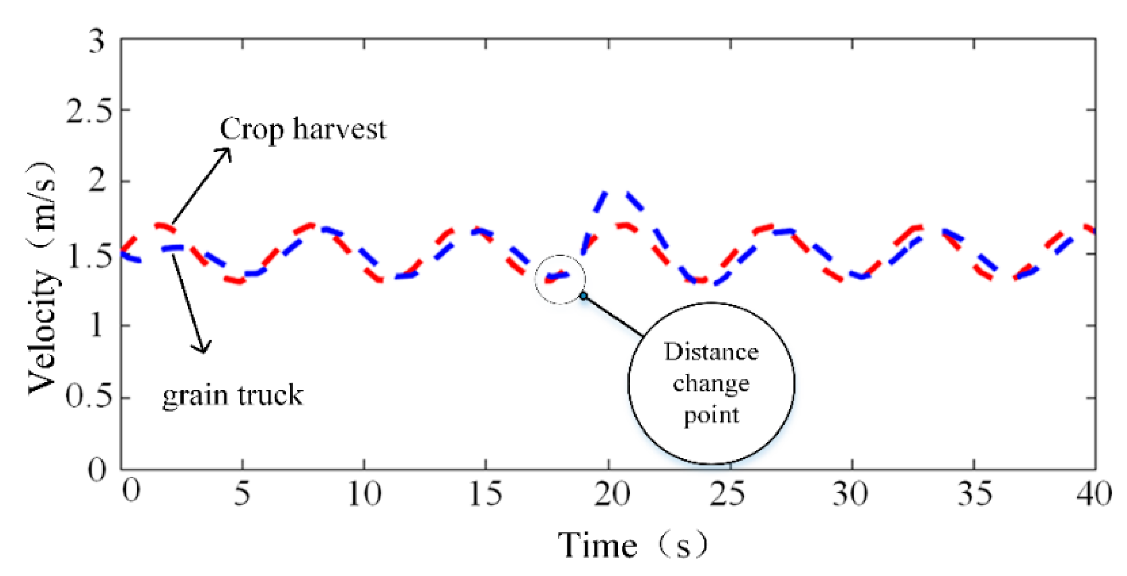
Take k = 1 , m = 360 kg , and the other parameters are consistent with the simulation settings above. The simulation sets the crop harvester to spit out 20 kg of grain per second, and the max of sprayed grain is 360 kg. It can be seen from Figure 8 that the crop harvester is in front of the first 5 s, the grain transporter is behind, and the grain transporter gradually follows the velocity of the crop harvester. After 5 s, the dynamic tracking balance is reached. After the grain truck accumulates standard quality crops in about 18 s, the following strategy is triggered. The grain truck starts to increase the velocity, adjust the distance between the two vehicles, and reaches a new balance after 25 s, which verifies the proposed method in this paper.

5.2. Real-Vehicle Test

The purpose of this paper is to realize the cooperative following operation of agricultural vehicles. To realize the cooperative follow-up operation of agricultural vehicles, in order to verify the effectiveness of the proposed control algorithm, a real-vehicle test is carried out combined with two small electric vehicles modified independently, as shown in Figure 9a. Considering that the robot has great differences in power and maximum speed compared with the real tractor, the verification experiment in this paper limits the experimental conditions to flat and firm roads with low-speed marching. At the same time, the experimental site is located on an open and flat road, which meets the requirements of receiving stable GPS satellite signals, and also minimizes the interference of the robot itself to the verification experiment in the experiment, set the parameter as Z p = 0.6 , Z i = 0.2 , Z v = 0.7 , Z a = 0.3 , τ = 0.15 , k = 1 .
The test vehicle used in this paper only controls the velocity precisely, without acceleration control. To control the acceleration of the controlled vehicle, the algorithm needs to obtain the relationship between acceleration and velocity. Therefore, through the velocity change test of the vehicle, the relationship between velocity and acceleration is calibrated, and the conversion relationship between acceleration and velocity is obtained in Figure 9b. The vehicle acceleration and deceleration controls obtain the control command by interpolating the current vehicle velocity and the expected acceleration look-up table.
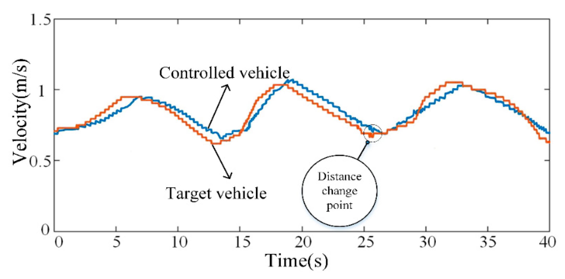
Figure 10 shows the velocity response of the following vehicle when the preceding vehicle is traveling at a velocity of about 0.75 m/s. The target vehicle accelerates in the first 5 s and accelerates to 0.9 m/s in the 5 s; then decelerates; at the 13th second, it decelerates to a minimum velocity of 0.6 m/s, and then periodically accelerates and decelerates. The desired distance between the two vehicles in the first 25 s is 2 m, and the expected following distance is adjusted to 1.85 m in the 25 s. It can be observed from the diagram that although the velocity response curve of the controlled vehicle lags behind the velocity curve of the target vehicle, the lag time difference is very short and does not affect the movement of the controlled vehicle following the target vehicle. In addition, there is no obvious excessive response to the velocity of the controlled vehicle, which indicates that the velocity fluctuation of the target vehicle does not have the phenomenon of fluctuation amplification when it is transmitted to the controlled vehicle, which satisfies the following stability.
The following distance between the two vehicles is shown in Figure 11. Combining Figure 11a and Figure 11b, it can be seen that the following distance of the two vehicles overshoots from 0 to 13 s, the maximum overshoot is 0.219 m, and then the vehicle tends to be stable, the steady-state following error is 0.12 m, after 25 s, the expected vehicle distance affects strongly, overshoot occurs again, the maximum overshoot is 0.138 m, the following distance between 33 s and 35 s tends to be stable, the steady-state error is less than 0.1 m, and after 35 s, the expected vehicle distance is 1.85 m. The fluctuation tends to be stable.
The real-vehicle test results show that the system is affected by the velocity fluctuation of the preceding vehicle, the rear vehicle can effectively follow the preceding vehicle, and the stability is good. When the desired distance changing, at first, some overshooting increases and then tends to be stable. The system has robustness.
The velocity response effect of the algorithm proposed in this paper is verified in real vehicles, and the velocity diagrams of the two vehicles are shown in Figure 12. The driving process of the target vehicle is divided into two stages, the first stage is the variable velocity driving stage, and the second stage is the constant velocity driving stage. It can be seen from the figure that the target vehicle frequently accelerates and decelerates from 0 to 15 s and gradually accelerates to the desired velocity of 1 m/s after 15 s. After stabilization, the vehicle velocity fluctuates around 1 m/s. In the process of variable velocity driving, although the velocity of the controlled vehicle lags behind the target vehicle, it can keep up with the velocity change of the target vehicle. After 20 s, the target vehicle began to drive at a constant velocity, and the velocity of the target vehicle fluctuated slightly, and the controlled vehicle could follow. The actual vehicle following effect is consistent with the theoretical analysis, and it is preliminarily verified that the algorithm in this paper can realize the stable following of the controlled vehicle to the target vehicle on the real road.
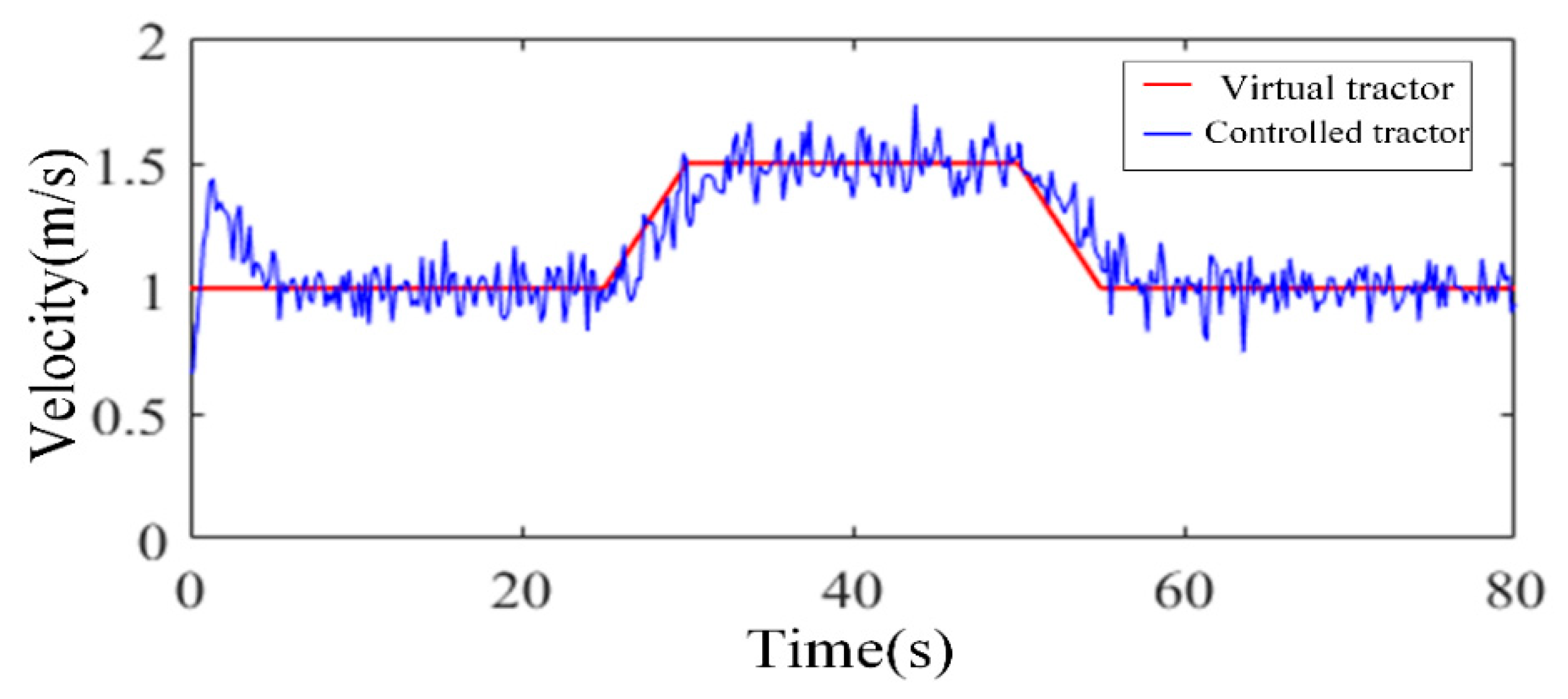
To verify the control effect of the algorithm in real land, use the modified New Holland 1404 (CNH Industrial N.V. London, United Kingdom) as the test tractor to conduct the virtual tractor real-vehicle test of the charged tractor following the preceding vehicle, set the parameter as Z p = 0.6 , Z i = 0.2 , Z v = 0.7 , Z a = 0.3 , τ = 0.15 , s initial distance between vehicles is 4 m. Set the virtual tractor speed as shown in Figure 13. the virtual tractor initial speed is 1 m/s, accelerate at time 25 s, when the time hits 30 s, the speed increased to 1.5 m/s; the speed starts to decelerate from 50 s, after 5 s the speed decelerate to 1m/s. From the figure, we can see that, from the beginning 5 s, to keep the same speed as the virtual tractor, the controlled tractor has a large speed overshoot at the initial stage of acceleration; in about 5 s, the controlled tractor keeps up with the speed change of the virtual tractor. At 25 s, due to the virtual tractor speed change, the controlled tractor keeps up with the front tractor slowly, also no overshooting during the process. Finally, after the deceleration procedure, the tractor keeps 1 m/s speed, following the virtual tractor. The actual vehicle test results show that the tractor following effect is in line with the theoretical analysis. The validity of the parameter selection method of the algorithm in this paper is verified, and the controlled tractor can follow the virtual tractor stably on the real soil.

6. Conclusions

Aiming at the problem of cooperative operation between grain transporter and crop harvester, a vehicle following controller is designed with grain transporter as the controlled object. The conclusion follows below.
According to the operating characteristics of grain trucks and crop harvesters, a follow-up strategy for agricultural machinery that can adaptively adjust the following distance based on the weight of grain trucks is proposed. The experimental results show that the follow-up strategy is feasible.
By establishing the kinematics differential equation and combining it with the vehicle following strategy, an agricultural machinery following control algorithm considering vehicle load change and control delay is designed. By constructing the transfer function, the influence of each parameter on the stability region is analyzed in detail, and the optimal interval of the parameter is obtained.
The simulation experiment and real-vehicle test results show that the following strategy and algorithm designed in this paper have certain stability and robustness, and the parameter selection method has certain feasibility and effectiveness.

Author Contributions

Conceptualization, K.C. and Z.M.; methodology, Z.M., H.Y.; software, K.C.; validation, K.C. and S.M.; formal analysis, S.M.; investigation, Y.Y.; resources, Z.M.; data curation, K.C.; writing—original draft preparation, K.C.; writing—review and editing, S.M., Z.M., K.C.; visualization, K.C.; supervision, W.F.; project administration, C.Z.; funding acquisition, S.M. All authors have read and agreed to the published version of the manuscript.

Funding

This research was funded by the National Key Research and Development Program of China, grant number 2019YFB1312304 and Key R&D Program of Hebei Province, grant number 22327204D, 201227168, 19227208D.

Institutional Review Board Statement

Not applicable.

Data Availability Statement

Not applicable.

Acknowledgments

The authors gratefully acknowledge the editors and anonymous reviewers for their constructive comments on our manuscript.

Conflicts of Interest

The authors declare no conflict of interest.

References

  1. Backman, J.; Oksanen, T.; Visala, A. Navigation system for agricultural machines: Nonlinear model predictive path tracking. Comput. Electron. Agric. 2012, 82, 32–43. [Google Scholar] [CrossRef]
  2. Subramanian, V.; Burks, T.F.; Arroyo, A.A. Development of machine vision and laser radar based autonomous vehicle guidance systems for citrus grove navigation. Comput. Electron. Agric. 2006, 53, 130–143. [Google Scholar] [CrossRef]
  3. Kayacan, E.; Kayacan, E.; Ramon, H.; Saeys, W. Towards agrobots: Identification of the yaw dynamics and trajectory tracking of an autonomous tractor. Comput. Electron. Agric. 2015, 115, 78–87. [Google Scholar] [CrossRef]
  4. Oksanen, T. Laser scanner based collision prevention system for autonomous agricultural tractor. Agron. Res. 2015, 13, 167–172. [Google Scholar]
  5. Li, S.; Xu, H.; Ji, Y.; Cao, R.; Zhang, M.; Li, H. Development of a following agricultural machinery automatic navigation system. Comput. Electron. Agric. 2019, 158, 335–344. [Google Scholar] [CrossRef]
  6. Hu, J.; Gao, L.; Bai, X.; Li, T.; Liu, X. Review of research on automatic guidance of agricultural vehicles. Trans. Chin. Soc. Agric. Eng. 2015, 31, 1–10. [Google Scholar]
  7. Li, S.; Li, K.; Rajamani, R.; Wang, J. Model predictive multi-objective vehicular adaptive cruise control. IEEE Trans. Control Syst. Technol. 2010, 19, 556–566. [Google Scholar] [CrossRef]
  8. Cheng, T.M.; Savkin, A.V.; Javed, F. Decentralized control of a group of mobile robots for deployment in sweep coverage. Robot. Auton. Syst. 2011, 59, 497–507. [Google Scholar] [CrossRef]
  9. Iida, M.; Kudou, M.; Ono, K.; Umeda, M. Automatic following control for agricultural vehicle. In Proceedings of the 6th International Workshop on Advanced Motion Control, Nagoya, Japan, 30 March–1 April 2000. [Google Scholar]
  10. Noguchi, N.; Will, J.; Reid, J.; Zhang, Q. Development of a master–slave robot system for farm operations. Comput. Electron. Agric. 2004, 44, 1–19. [Google Scholar] [CrossRef]
  11. Zhang, M.; Ji, Y.; Li, S. Research progress of agricultural machinery navigation technology. Trans. Chin. Soc. Agric. Mach. 2020, 51, 1–18. [Google Scholar]
  12. Zhang, C.; Noguchi, N.; Yang, L. Leader–follower system using two robot tractors to improve work efficiency. Comput. Electron. Agric. 2016, 121, 269–281. [Google Scholar] [CrossRef]
  13. Zhang, X.; Geimer, M.; Noack, P.O.; Grandl, L. Development of an intelligent master-slave system between agricultural vehicles. In Proceedings of the 2010 IEEE Intelligent Vehicles Symposium, La Jolla, CA, USA, 21–24 June 2010; pp. 250–255. [Google Scholar]
  14. Bai, X.; Wang, Z.; Hu, J.; Gao, L.; Xiong, F. Harvester group corporative navigation method based on leader-follower structure. Nongye Jixie Xuebao/Trans. Chin. Soc. Agric. Mach. 2017, 48, 14–21. [Google Scholar]
  15. Bai, X.; Hu, J.; Wang, Z. Slave positioning method for cooperative navigation of combine harvester group based on visual servo. Trans. Chin. Soc. Agric. Eng. 2016, 32, 59–68. [Google Scholar]
  16. Xu, G.; Chen, M.; Miao, H.; Yao, W.; Diao, P.; Wang, W. Following Operation Control Method of Farmer Machinery Based on Model Predictive Control. Nongye Jixie Xuebao/Trans. Chin. Soc. Agric. Mach. 2020, 51, 11–20. [Google Scholar]
  17. Lee, K.H.; Ehsani, R.; Schueller, J.K. Forward movement synchronization of two vehicles in parallel using a laser scanner. Appl. Eng. Agric. 2007, 23, 827–834. [Google Scholar] [CrossRef]
  18. Luo, C.; Mohsenimanesh, A.; Laguë, C. Synchronous Tracking Control for Agricultural Wide-Span Implement Carrier (WSIC). Trans. ASABE 2018, 61, 873–883. [Google Scholar] [CrossRef]
  19. Zhu, Z.; Takeda, J.; Xie, B.; Song, Z.; Torisu, R.; Mao, E. Tractor platooning system on sloping terrain at low speed. Trans. ASABE 2009, 52, 1385–1393. [Google Scholar] [CrossRef]
  20. Vougioukas, S.G. A distributed control framework for motion coordination of teams of autonomous agricultural vehicles. Biosyst. Eng. 2012, 113, 284–297. [Google Scholar] [CrossRef]
  21. Hao, Y.; Laxton, B.; Benson, E.R.; Agrawal, S.K. Differential flatness-based formation following of a simulated autonomous small grainharvesting system. Trans. ASAE 2004, 47, 933. [Google Scholar] [CrossRef]
  22. Jensen, M.A.F.; Bochtis, D.; Sørensen, C.G.; Blas, M.R.; Lykkegaard, K.L. In-field and inter-field path planning for agricultural transport units. Comput. Ind. Eng. 2012, 63, 1054–1061. [Google Scholar] [CrossRef]
  23. Li, D.; Li, Z. System Analysis and Development Prospect of Unmanned Farming. Nongye Jixie Xuebao/Trans. Chin. Soc. Agric. Mach. 2020, 51, 1–12. [Google Scholar]
  24. Shafi, U.; Mumtaz, R.; García-Nieto, J.; Hassan, S.A.; Zaidi, S.A.R.; Iqbal, N. Precision agriculture techniques and practices: From considerations to applications. Sensors 2019, 19, 3796. [Google Scholar] [CrossRef] [PubMed]
  25. Zhang, F.; Zhang, W.; Luo, X.; Zhang, Z.; Lu, Y.; Wang, B. Developing an IoT-Enabled Cloud Management Platform for Agricultural Machinery Equipped with Automatic Navigation Systems. Agriculture 2022, 12, 310. [Google Scholar] [CrossRef]
  26. Amiri-Zarandi, M.; Hazrati Fard, M.; Yousefinaghani, S.; Kaviani, M.; Dara, R. A Platform Approach to Smart Farm Information Processing. Agriculture 2022, 12, 838. [Google Scholar] [CrossRef]
  27. Zhang, W.; Gong, L.; Chen, S.; Wang, W.; Miao, Z.; Liu, C. Autonomous identification and positioning of trucks during collaborative forage harvesting. Sensors 2021, 21, 1166. [Google Scholar] [CrossRef] [PubMed]
  28. Shearer, S.A.; Pitla, S.K.; Luck, J.D. Trends in the automation of agricultural field machinery. In Proceedings of the 21st Annual Meeting of the Club of Bologna, Bologna, Italy, 13–14 November 2010. [Google Scholar]
  29. Chehardoli, H.; Ghasemi, A. Adaptive centralized/decentralized control and identification of 1-D heterogeneous vehicular platoons based on constant time headway policy. IEEE Trans. Intell. Transp. 2018, 19, 3376–3386. [Google Scholar] [CrossRef]
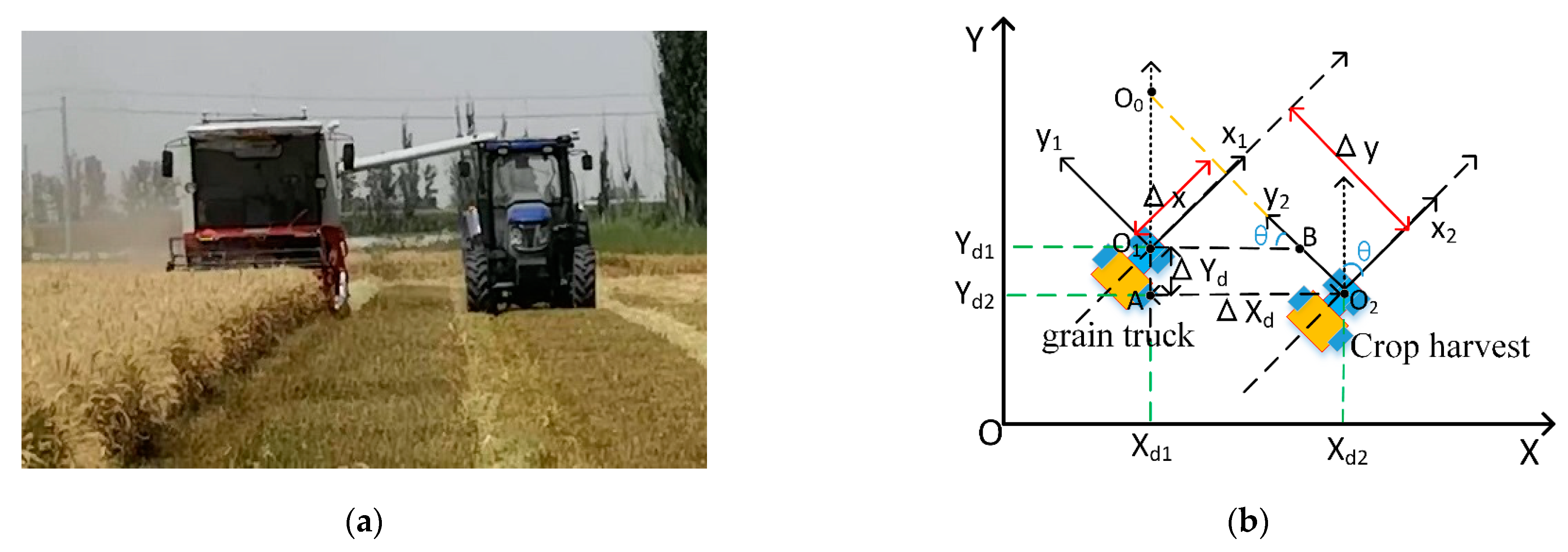
Figure 1. Cooperative operation of agricultural machinery and transformation of vehicle coordinate system. (a) Cooperative operation of agricultural machinery; (b) Transformation of coordinates.
Agriculture 12 01545 g001
Figure 2. (a) Grain truck and crop harvester follow system stability; (b) Bode diagrams of stability at different boundaries.
Agriculture 12 01545 g002
Figure 3. Stable region diagram under the influence of delay parameters τ . (a) τ = 0.1 ; (b) τ = 0.15 (c) τ = 0.2 .
Agriculture 12 01545 g003
Figure 4. Stability region diagram under the influence of parameters Za. (a) Za = 0.2; (b) Za = 0.4; (c) Za = 0.6; (d) Za = 0.8.
Agriculture 12 01545 g004
Figure 5. Stability region diagram under the influence of parameters Z i . (a) Z i = 0.1 ; (b) Z i = 1 ; (c) Z i = 1.9 .
Agriculture 12 01545 g005
Figure 6. Error diagram of two vehicles’ velocity and desired distance. (a) Z p = 0.6 ; (b) Z p = 0.2 ; (c) Z p = 0.1 .
Agriculture 12 01545 g006
Figure 7. Following simulation diagram under the influence of velocity magnitude fluctuation. (a) Low magnitude high frequency; (b) High magnitude high frequency; (c) Low magnitude low frequency; (d) High magnitude low frequency.
Agriculture 12 01545 g007
Figure 8. Changes in vehicle distance caused by changes in vehicle crop weight.
Agriculture 12 01545 g008
Figure 9. (a)Experimental system; (b) Acceleration–elocity conversion diagram at different vehicle velocity.
Agriculture 12 01545 g009
Figure 10. Following velocity diagram.
Agriculture 12 01545 g010
Figure 11. Follow distance diagram and distance error diagram. (a) diagram of the distance between two vehicles; (b) Error diagram of distance between two vehicles.
Agriculture 12 01545 g011
Figure 12. Convergence diagram of velocity from variable velocity to constant velocity.
Agriculture 12 01545 g012
Figure 13. Tractor velocity following diagram.
Agriculture 12 01545 g013
Publisher’s Note: MDPI stays neutral with regard to jurisdictional claims in published maps and institutional affiliations.