Article

Optimization Design and Simulation Experiment of a Press Roller Based on a Lemniscate-Shaped Curve in Rice–Wheat Rotation Region of China

Nanjing Institute of Agricultural Mechanization, Ministry of Agriculture and Rural Affairs, Nanjing 210014, China
*
Author to whom correspondence should be addressed.
Agriculture 2022, 12(10), 1599; https://doi.org/10.3390/agriculture12101599
Submission received: 10 August 2022 / Revised: 8 September 2022 / Accepted: 16 September 2022 / Published: 2 October 2022
(This article belongs to the Section Agricultural Technology)

Abstract

:
In order to solve the problems of high forward-resistance and serious soil adhesion in a rice–wheat rotation area, the smooth press roller of a wheat planter in a rice–wheat rotation area was selected as the research object. The low resistance and the adhesion structure of the press roller on a lemniscate-shaped curve were considered, and the geometric design method was adopted to modify the geometric structure of the smooth press roller. A simulation model of the roller–soil interaction was designed using the EDEM2020 software (DEM Solutions Ltd., Edinburgh, Scotland, UK), to investigate the behavior of soil adhering to the surface of the press roller, as well as the effects of the structure and the working parameters on soil adhesion and forward resistance. In addition, the numerical simulation method was combined with the central-plane composite response test scheme to perform the simulation test, using Design-Expert 10.0.4 software (Stat-Ease Inc., Minneapolis, MN, USA). In this test, the forward speed, the axial spacing, and the bulge height were taken as the test factors. On this basis, the working performance of the lemniscate curve type of the press roller was evaluated by establishing a response surface for soil adhesion and forward resistance. With the reduction in soil adhesion and the working resistance as constraints, the optimization was carried out under the condition of a forward speed of 7 km/h. Under a forward speed of 7 km/h, an axial spacing of 40.7–46.8 mm, and a bulge height of 9.3–11.5 mm, the soil adhesion was less than 70 g and the forward resistance was less than 50 N, meaning that the working performance of the lemniscate curve type of the press roller meets the requirements for actual production. In short, this research provides a new idea and reference for the application of a press roller in a rice–wheat rotation area.

1. Introduction

The press roller is the main soil-engaging component of a seed-sowing machine, and it can increase the seed and soil contact [1]. In the rice–wheat rotation region of middle China, the press roller type is relatively simple [2], and smooth press rollers are the typical press rollers used for wheat-seed sowing. In this region, when wheat sowing occurs in autumn [3,4], the soil, clayey paddy soil, is wet, which tends to adhere to the soil-engaging surface of the smooth press roller, resulting in high resistance and an inadequate wheat seedbed during the soil compaction process. At present, there are very few special press rollers for production in rice–wheat rotation area [5,6], and the conventional press rollers attached to the compound seeder do not have the ability to reduce viscosity, and the effect of soil compaction is usually poor. Soil adhesion is affected by many factors, such as the soil moisture content, travel speed, downforce, and geometry of the press roller. Press roller geometry is the best possible factor that can be altered to minimize soil adhesion [7]. Thus, it is necessary that a new type of press roller suitable for the sowing operation in rice stubble fields is designed, to meet the high-performance compaction operation of the sticky, heavy soil in the rice fields.
Over the last several decades, sowing technologies with regard to seed metering [8], the opener, and soil covering have matured, while the technology in respect of the press roller is still relatively weak, especially in the case of the anti-adhesion technology of the press roller. However, little research has been devoted to improving the performance of the smooth press roller for soil compaction. Guo Hui [9] designed an elastic press device row-sowing plow machine to solve the issue of soil adhesion. Zhao Jiale [10] designed an elastic covering-press roller based on the principles of an elastic flexible skin, where adhered soil can be removed by shaking. Wang Wenjun [11] designed a soil adhesion reduction and anti-slip structure for an elastic press roller, which has the advantages of less soil adhesion and more uniform pressure distribution. Chen Haitao [12] designed a three-way adjustable soil-compacting device with sufficient capacity for reducing soil viscosity. Chang Yuan [13] applied a bionic convex hull geometry design to the press roller surface, which changed the morphology of the contact surface between the press roller and the soil. Zhang Qingzhu [14] designed a bionic ridge geometric structure for a press roller, according to the geometric structure of the side of a dung beetle. Zhang Zhihong [15] applied the bionic technical method of a geometric structure to the design of a convex tooth wheel. These studies have shown that transforming the geometrically structured surfaces of a smooth press roller can reduce adhesion by 3–35%, compared with that of a smooth press roller. Thus, finding a new convex hull structure to improve the performance of the smooth press roller is the main goal of this paper.
The discrete element method (DEM) has been used by many researchers to simulate and optimize the soil-engaging component of a seed-sowing machine [16,17]. Compared to the finite element method (FEM), DEM, which is widely used to simulate the compaction produced by rollers [18], is suitable for analyzing the roller–soil interaction [19]. In the past decade, DEM press roller studies have been performed for the prediction of soil dynamic behavior [20]. In these studies, DEM was used to predict roller forces and soil disturbance. Sinkage, draft, and vertical force parameters have been predicted with DEM; however, soil adhesion behavior has not yet been studied. Understanding soil adhesion behavior is important, since it correlates with the roughness of the soil surface, which determines the growth of the wheat roots and the wheat yield. When soil adhesion behavior occurs, forward resistance increases, which increases financial losses for farmers. Therefore, in this study we focused on DEM type analysis and its capability for describing soil adhesion under driven press rollers.
The research objectives of this paper were (1) to design the lemniscate curve type of the press roller to solve the problems of serious soil adhesion and high resistance during wheat autumn sowing in a rice–wheat rotation area, (2) to investigate the study the working resistance and soil adhesion during the working of the press roller by using EDEM2020 software, and (3) to obtain the optimum working parameters with a virtual simulation methodology and multi-objective optimization methodology. Overall, this research provides new methods and references for the design and application of a press roller.

2. Materials and Methods

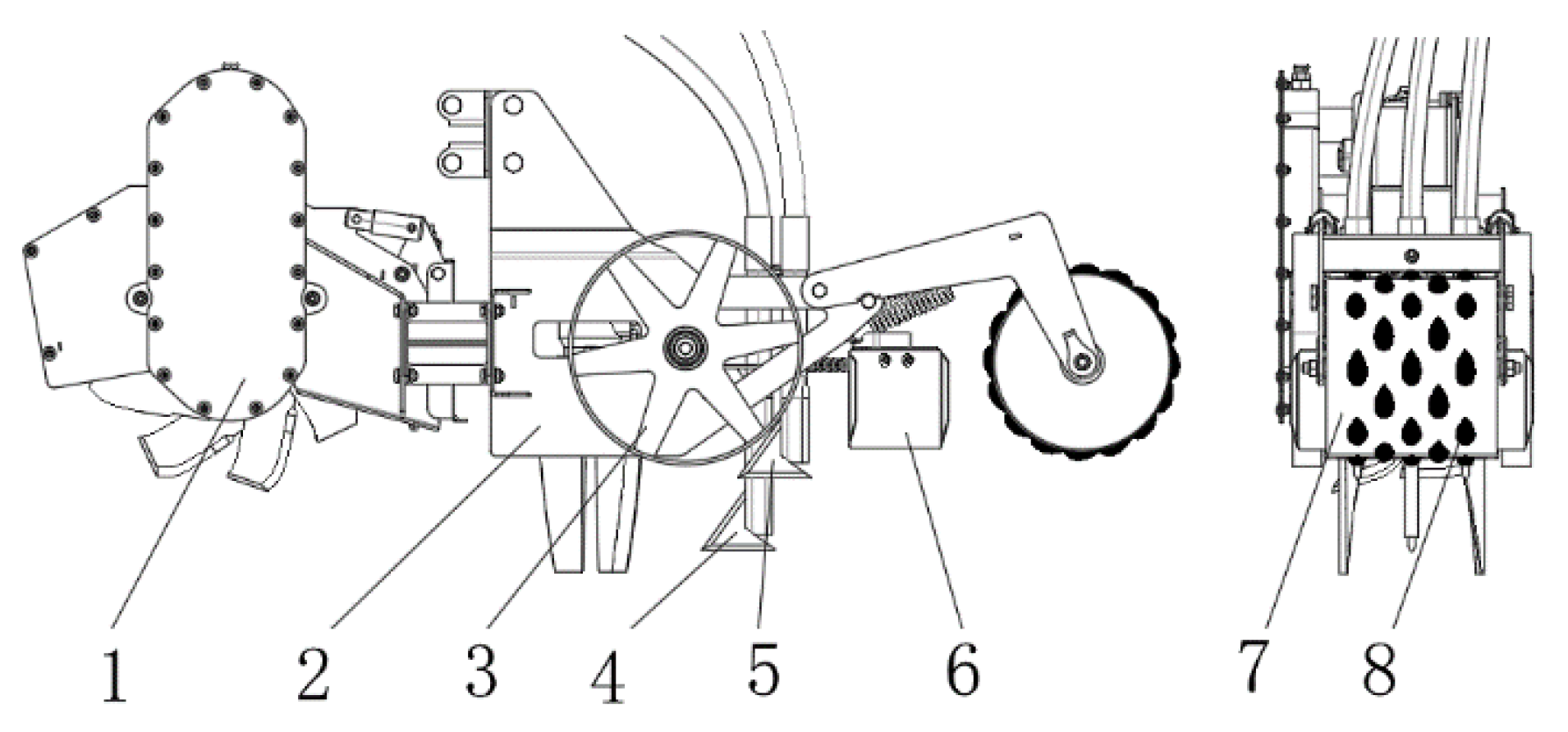
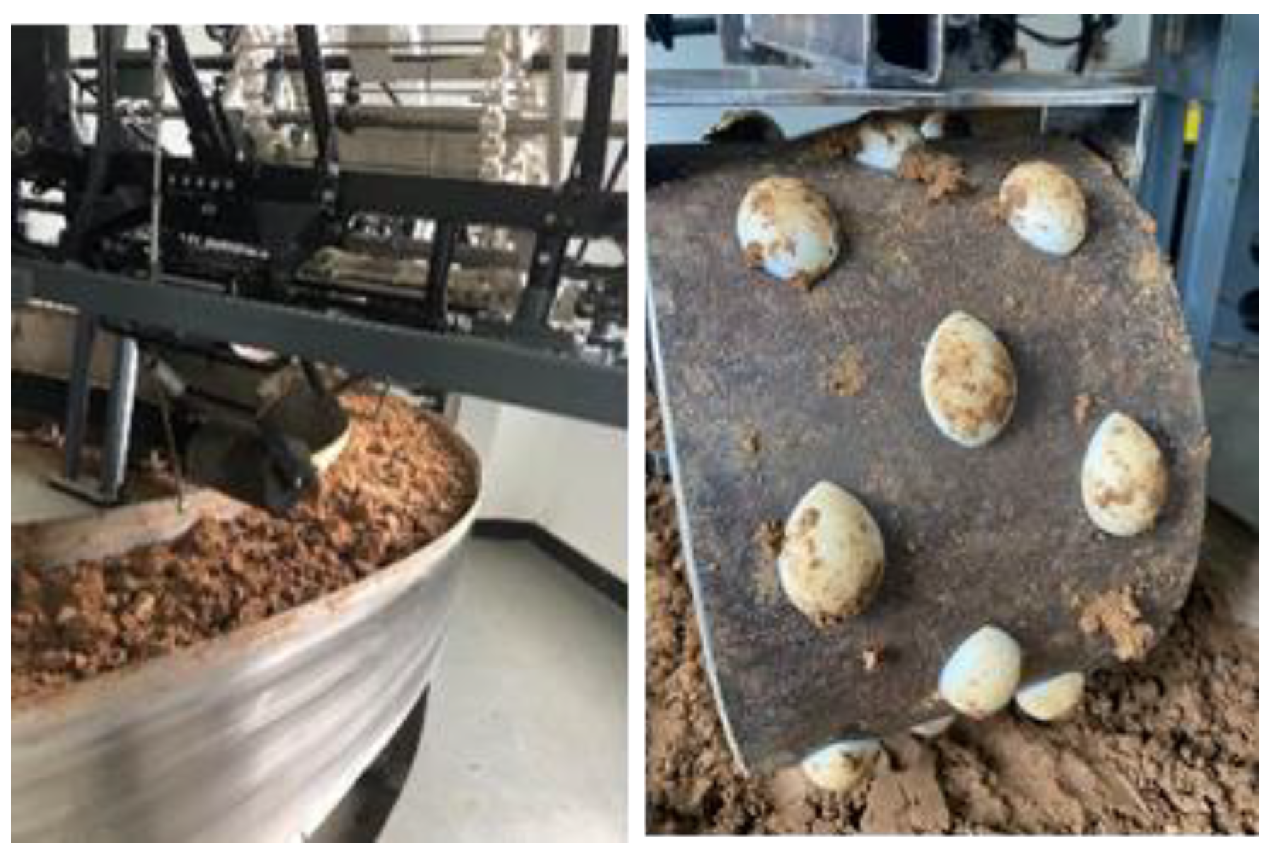
2.1. Machine Structure and Working Principles

2.1.1. Machine Structure with a Non-Smooth Press Roller

As shown in Figure 1, the wheat sowing unit in the rice–wheat rotation area with a non-smooth press roller includes four parts: the soil preparation device, the seed sowing and deep fertilization device, the soil covering device, and the soil compaction device. The key component of the soil compaction device is the non-smooth press roller, which consists of a smooth press roller and small convex hull structures. The main technical parameters of the non-smooth press roller are as follows: (1) a width of 260 mm; (2) an axial spacing distance between adjacent convex hulls of 40–50 mm; (3) a phase angle difference between the adjacent convex hulls in the longitudinal direction of 45°; (4) a downforce of 0~800 N; and (5) a forward speed of 3–7 km/h.

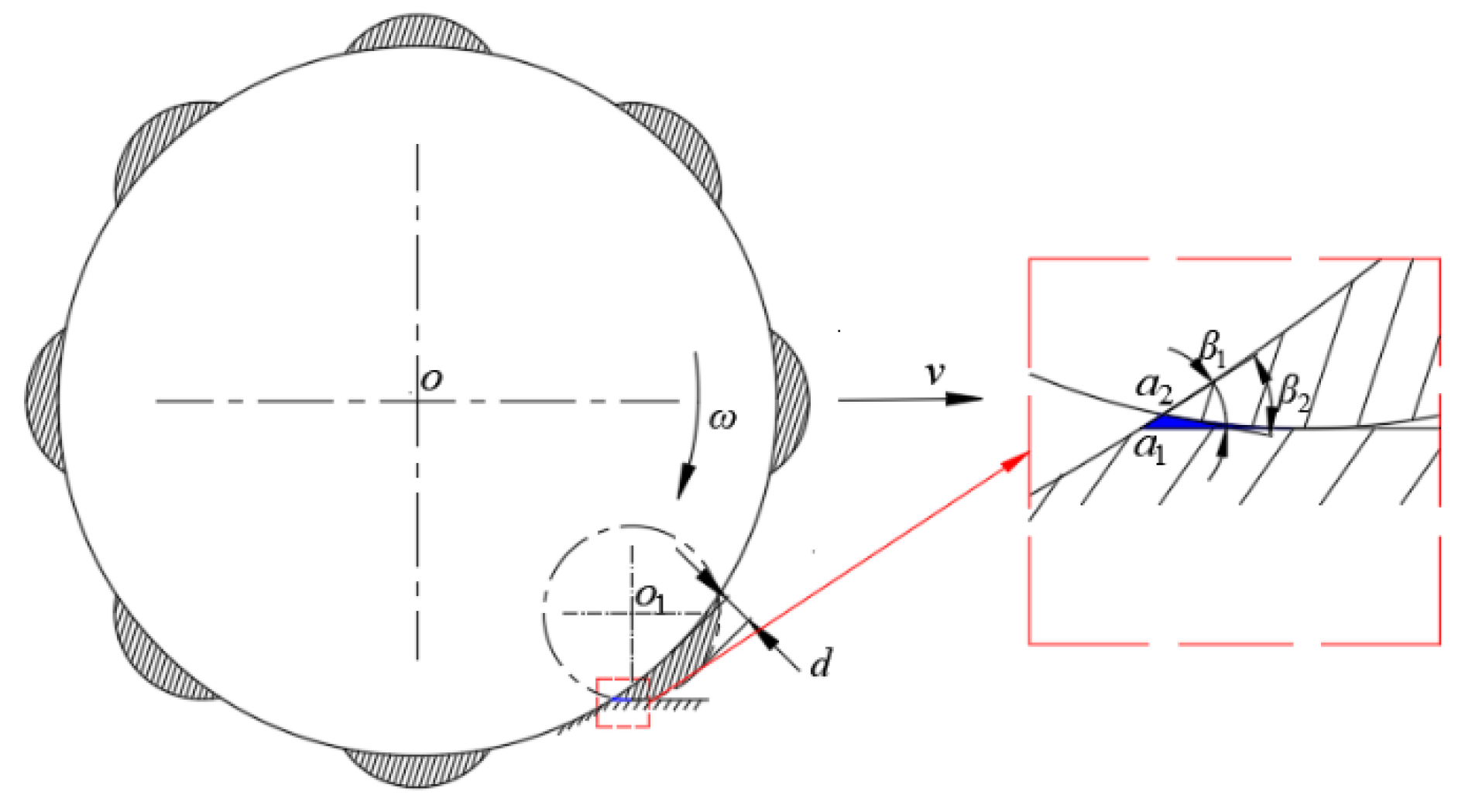
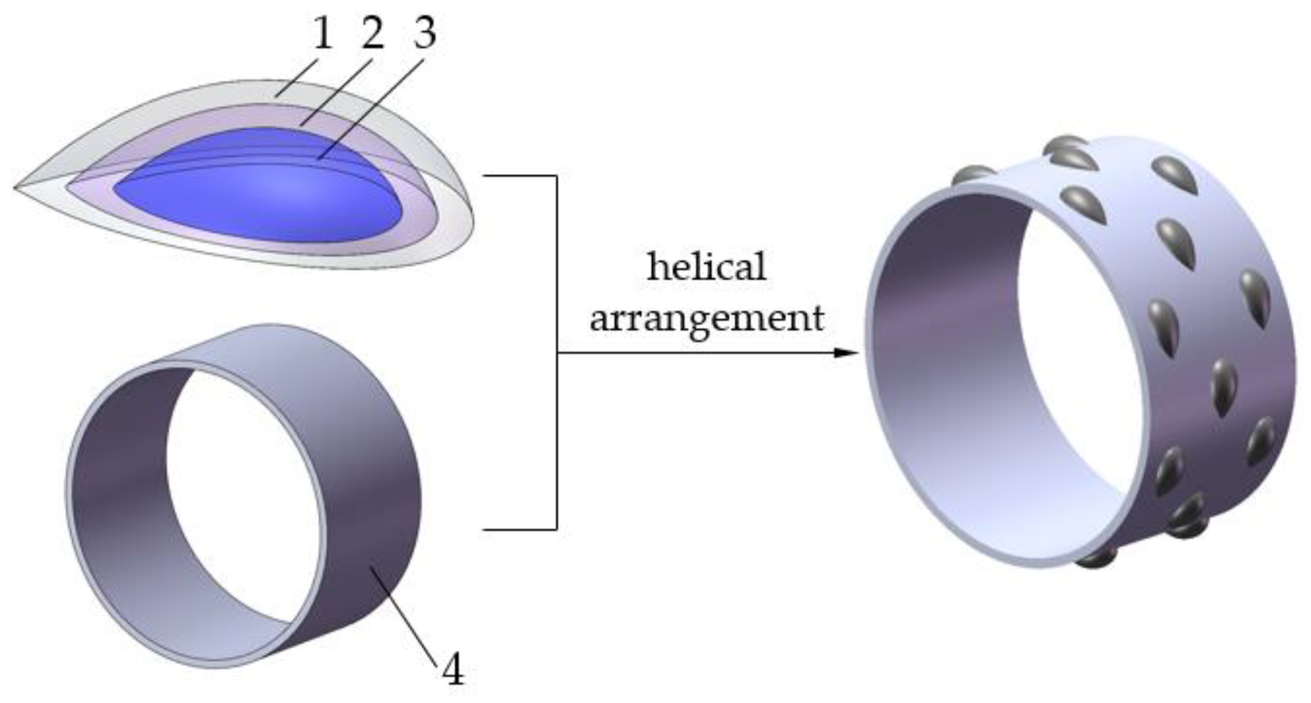
2.1.2. Design of the Low-Adhesion and Low-Resistance Structure of the Press Roller

The dimensions of the longitudinal profile line, the transverse profile line, and the convex bale structure (length, width, and height) determine the actual operation performance of the convex bale, of which the longitudinal profile line is the key parameter. During the press operation, the movement state and displacement change of the soil are related to the appearance of the edge line of soil contact, and the relative relationship between the arc convex contour curve and the soil position is analyzed, as shown in Figure 2, so as to ensure the rationality of the design.
As shown in Figure 2, when β2 > β1, a vacuum region (blue region) is formed, which easily accumulates soil, and thus, this affects the viscosity reduction and resistance reduction properties of the convex cladding, so the angle of β2 should be controlled. Furthermore, when the slope of the second half of the edge line changes greatly, the contact area with the soil will be reduced, and thus the possibility of collision will be reduced. In summary, the double button line with a low slope of the front section and the high slope of the back section (lemniscate curve) is selected as the longitudinal contour curve of the convex hull. Considering that the lemniscate curve is the same in the four quadrants of the x,y coordinate system, we select the double button line in the first quadrant as the contour curve equation, and the equation expression is as follows:
( x 2 + y 2 ) 2 = a 2 ( x 2 y 2 ) ( x 0 , y 0 )
where a is the equation coefficient, x is the x-coordinate value, and y is the y-coordinate.
Equation (1) is rearranged into an equation in respect of y:
y 2 = a 2 4 + 2 a x 2 ( x 2 + a 2 )
The spatial coordinate system o-xyz is established, and the curve of the effective section of the lemniscate curve rotates around the x axis to form a convex hull, whose outer contour is in the shape of a middle convex tip, as shown in Figure 3. The mathematical expression of the surface rotating about the x axis is as follows:
y 2 + z 2 = a 2 4 + 2 a x 2 ( x 2 + a 2 )
where z is the z-coordinate.
According to the relative position relationship in Figure 3, the mathematical relationship between the equation coefficient a and the base circle of radius R is determined, as shown in Equation (4).
2 R sin ( θ 2 ) = a
In this paper, the value of R is 150 mm, and the corresponding θ is less than 23°, which determines the value of a in a range 0–60 mm, using Equation (4).
The Key Laboratory of Engineering Bionics of the Ministry of Education of Jilin University found that the bulge height d of the convex hull suitable for the press roller (diameter: 300 mm) is in the range 5–20 mm. Given that after the rotary tillage treatment of rice stubble fields the soil still has much agglomeration, the bulge height of the convex hull should be appropriately increased to improve the soil flow to a certain extent, and also to ensure the stability of the operation. Referring to the literature [21] and pre-experiments, the height d of the convex hull is determined to be less than 14 mm and more than 8 mm. When a is 60, the corresponding height is 14 mm; in this paper, the other height is based on the bulge height in a reduction coefficient to zoom out. It can be seen from the literature [22] that the corresponding sag of the press roller (300 mm in diameter) under the action of the load (300 N) is approximately 19 mm, and the β1 angle is 29°. At this time, the β2 angle corresponding to the convex hull is 29°, indicating that forming a vacuum zone is difficult, and the design meets the requirements of viscosity reduction.
The length and width of the convex hull are the driven dimensions of the bulge height of the convex hull. The relative positional relationship between the lemniscate curve and the edge line of the base circle is represented by the width and length of the Boolean operation on the complete convex hull and a base circle with a radius of 150 mm, using Solidworks 2018 software (Dassault Systèmes S.E., Massachusetts, Concord, MA, USA).

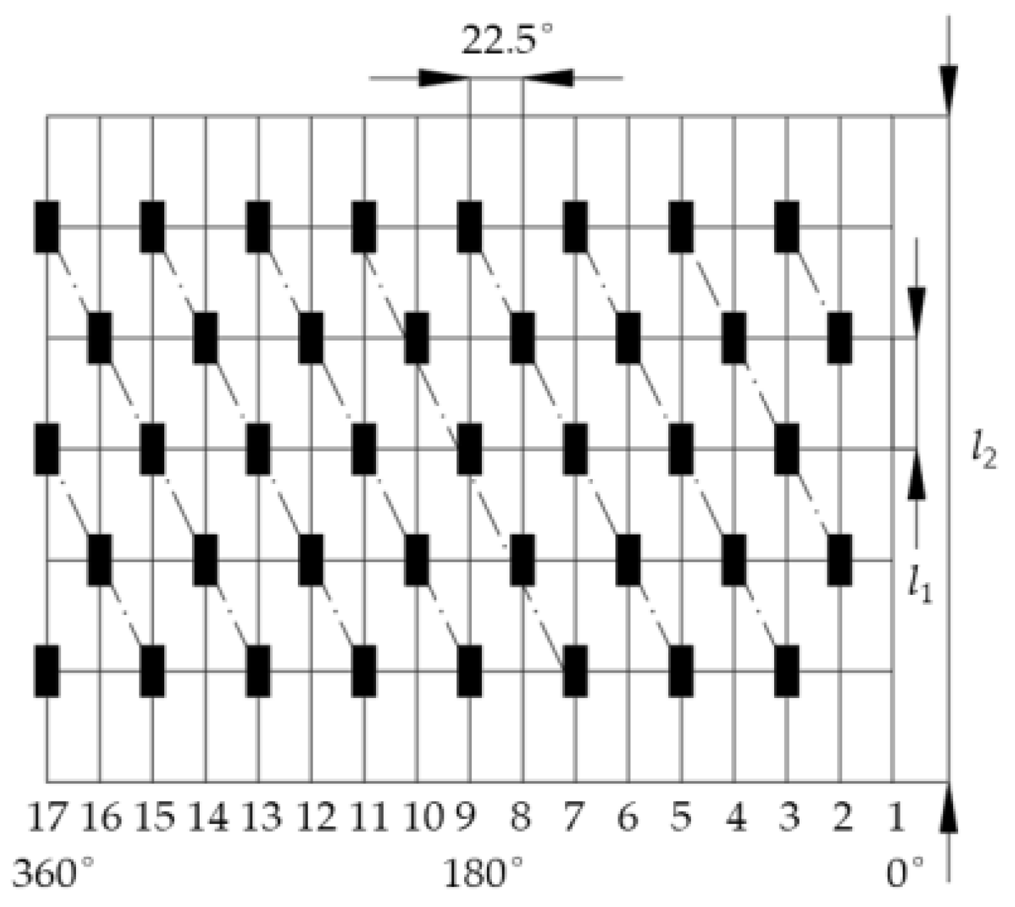
2.1.3. Arrangement of the Convex Geometrical Structure on the Press Roller

The arrangement of the convex geometrical structure can significantly influence the vibration and force of the press device. Thus, the horizontal and vertical balance should be achieved as far as possible when designing the convex geometrical structure arrangement. Referring to the literature [13], a helical arrangement is used to ensure the balance of the axial force, and the radial angle is 22.5°, as shown in Figure 4. In this paper, the lateral width of the press roller is l2, and l2 is 220 mm. Beyond that, the axial distance of the adjacent two sets of convex geometrical structures is equal to l1, and the total number of convex geometrical structures is decided on the basis of l1, values for which are 30, 40, and 50 mm. When the press roller operates according to the arrangement of the press roller, two convex hulls only work simultaneously, which can reduce the fluctuation of working resistance, effectively decreasing the vibration and the force of the axle bearing when working under severe working conditions, and improving the service life of the machine, as shown in Figure 4. The process of constructing a non-smooth press roller for convex hulls and basal circles of different raised heights is shown in Figure 5.

2.2. Virtual Interaction Simulation Model Building

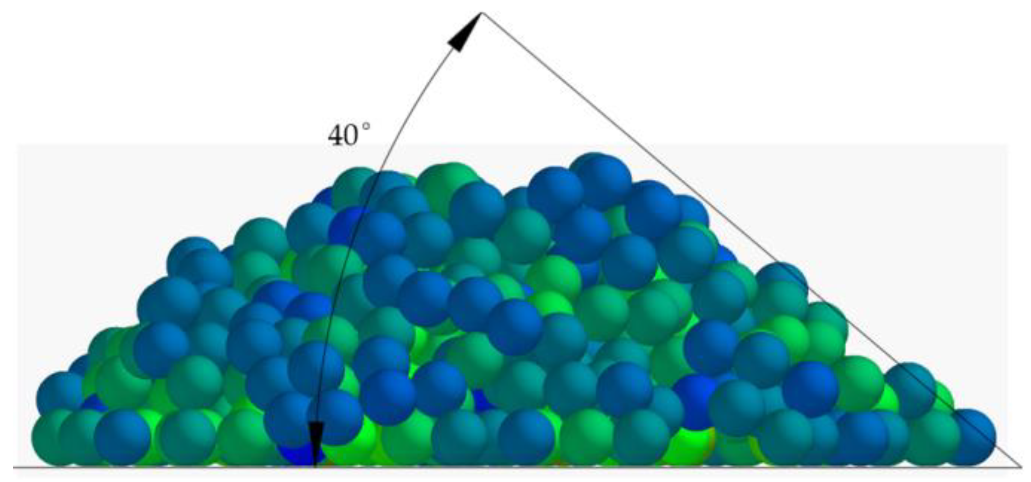
2.2.1. Selection of a Contact Model and Calibration of Model Parameters

In this paper, the phenomenon of soil adhesion was investigated. Therefore, the Hertz–Mindlin with JKR model was selected as the contact model between the soil particles and the press roller, and the Edinburgh-Elasto-Plastic-Adhesion Model (EEPA) was selected as the contact model between the soil particles.
Selecting appropriate model parameters is an important step for the accurate prediction of forward resistance and soil adhesion. The basic model parameters were the Poisson ratio, shear modulus, and density, which were obtained through experiments and the literature. The contact mechanical parameters were static friction coefficient, dynamic friction coefficient, and surface energy, which needed to be calibrated. Using the virtual parameter calibration scheme, the regression equation of the particle contact parameters and the angle of repose was established. Based on the regression equation, the contact mechanical parameters were obtained (Table 1); the actual angle of repose is 40.8°. Using the data in Table 1, the corresponding virtual angle of repose is 40°, as shown in Figure 6, and the relative error of the actual value is 2%. The contact mechanical parameters were calibrated for an accurate simulation of the interactions between the press roller and the soil simulant.

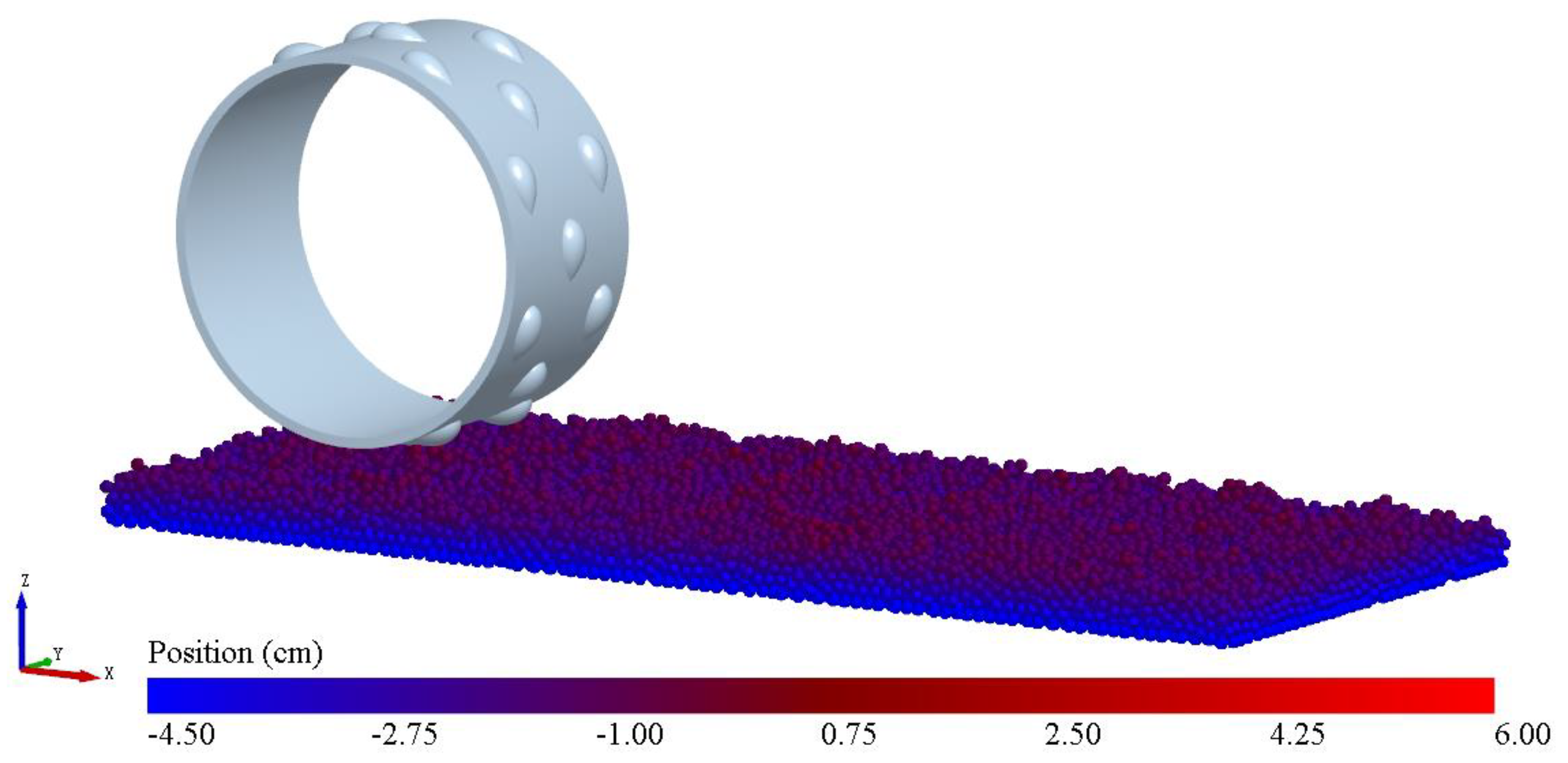
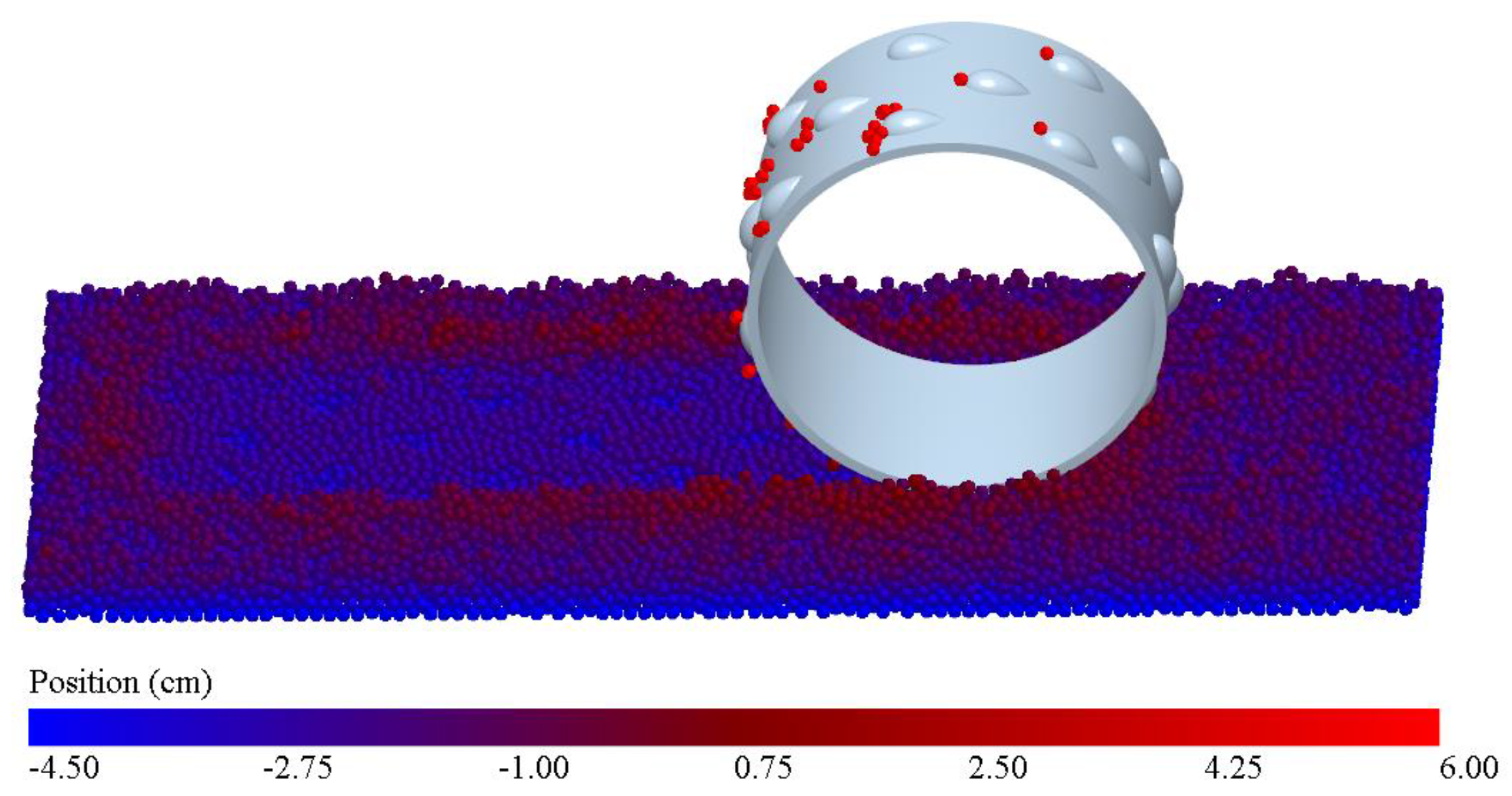
2.2.2. Virtual Soil–Roller Interaction Simulation Model

In order to control the simulation time and to improve the simulation accuracy, the irrelevant parts, such as bearings, side support plate, etc., were neglected [23,24,25], and the simulation model was constructed according to the design scheme in the previous section, using SolidWorks 2018 software. After model building, the 3D solid modeling file was saved in igs. format and imported into EDEM 2020 software. The position of the press roller was adjusted to be above the positive direction of the soil. The surface of the soil was not in contact with the bottom of the press roller. The distance between the soil and the press roller was 10 mm (Figure 7). The shape of the soil particles was spherical; the size of the soil particles was 5 mm, and the number of particles was 18,000. The particle generation speed of the virtual dynamic factory was 8000 per second (Figure 7). The color represents the relative position along the z axis. Figure 7 shows that the height of the topsoil is uneven, which is almost consistent with the actual soil state after soil covering.

2.2.3. Setting Boundary Conditions

During the simulation, the press roller descent speed was set to 0.05 m/s until the vertical force of the press roller became equal to 300 N. Then, for the press roller, the forward speed was specified by the follow-up test scheme; the rotational speed was computed using the forward speed and slippage; the slippage assigned was 0.95 for all tests; moving along the y−axis, the rotation along the x− and z−axes was completely restrained. When the press roller moved to the edge of the soil model, the simulation ended. In order to prevent soil particles from unrealistic splashing during the simulation, the Rayleigh time step was controlled to below 7%.

2.2.4. Analysis and Validation of the Simulation Results

According to the literature [24], although the index values of the press roller can be different, the state and law are similar under different working conditions. Therefore, the forward speed, the axial spacing, and the bulge height were selected as an example for studying the soil particles dynamic behavior, and the experimental values were set to 5 km/h, 50 mm, and 11 mm, respectively.
Figure 8 shows that there are particles adhering to the surface of the press roller; this phenomenon is close to the realistic situation, and indicates the reasonable selection of the contact model between the soil and the press roller. There are red particles behind the press roller, which fall off the surface of the press roller, showing that the parameters of the contact model are reasonable. Compared with the non-compacting area, the color of the soil particles in the compacting operation area is dark blue [26], indicating that the soil particles in the operation area move downward along the z-axis, and the local color is darker blue, which indicates the convex hull operation area.
The DEM model validation test was performed in the indoor annular soil trough of Nanjing Institute of Agricultural Mechanization, Ministry of Agriculture and Rural Affairs, with the experimental values for forward speed, axial spacing, and bulge height being set at 5 km/h, 50 mm, and 11 mm, respectively (Figure 9). The relative deviation between the simulation results and the actual results was less than 6%, which shows the feasibility of the simulation model.

2.3. Test Design and Treatment

As soil adhesion and forward resistance are important performance indexes for press rollers in Chinese rice–wheat rotations, soil adhesion Y1 and forward resistance Y2 were selected as the test indexes to reflect the working performance of the new press roller. In addition, the central composite face-centered design was used to optimize the working performance of the new press roller [27,28], using Design-Expert software 10.0.4(Stat-Ease Inc., Minneapolis, MN, USA). Due to soil conditions and cultivated area limitations in the rice–wheat rotation area, small– and medium–sized rotary tillage and seeding compound operation equipment is mainly used, and the general forward speed of seeding operation is between 1–8 km/h. In addition, the forward speed x1, axial spacing x2, and bulge height x3 were selected as the test factors, and the experimental values were set at 3–7 km/h, 40–50 mm, and 8–14 mm, respectively. The experimental factors and levels are displayed in Table 2.
The central composite face-centered method was used to code the test factors and levels, and 17 treatments were conducted according to Table 3. The test results are displayed in the Table 3.

3. Results and Analysis

3.1. Significance Test

Multivariate regression fitting was performed on the data in Table 3. As shown in Table 4 and Table 5, the regression models of the two indexes are highly significant (p < 0.01). This result indicates that the selected model is appropriate for the performance test of press roller based on a lemniscate-shaped curve, and there is a model determination relationship between test indexes and factors. Furthermore, the misfit is not significant (p > 0.1), indicating that the model is suitable for the performance test of press roller based on a lemniscate-shaped curve, that there are no uncontrolled factors affecting the indexes, and that the fitting effect of the model is good. In Table 4, the quadratic terms (x12, x22) are not significant (p > 0.1), while the other items are significant or very significant. In Table 5, the interactive items (x1x2, x2x3) and quadratic terms (x22) are not significant (p > 0.1), whereas the other items are significant or very significant.
After the insignificant items were eliminated in Table 4 and Table 5, variance analysis was performed to ensure that all the factors reached a significant or highly significant level. Then, the regression equation of the coded values of each factor was obtained. The regression equations of the soil adhesion and forward resistance can be expressed as follows:
Y 1 = 405.40 22.48 x 1 + 0.58 x 2 45.83 x 3 + 0.46 x 1 x 2 1.52 x 1 x 3 0.32 x 2 x 3 + 3.47 x 3 2
Y 2 =   438 . 45 + 21 . 73 x 1 19 . 11 x 2 6 . 77 x 3 0.43 x 1 x 3 1.44 x 1 2 + 0.22 x 2 2 + 0.44 x 3 2
Within the level range of the selected factors, according to the F value of each factor, the weights of the factors affecting the soil adhesion are forward speed x1 > bulge height x3 > axial spacing x2, and the weights of the factors affecting the forward resistance are forward speed x1 > axial spacing x2 > bulge height x3.

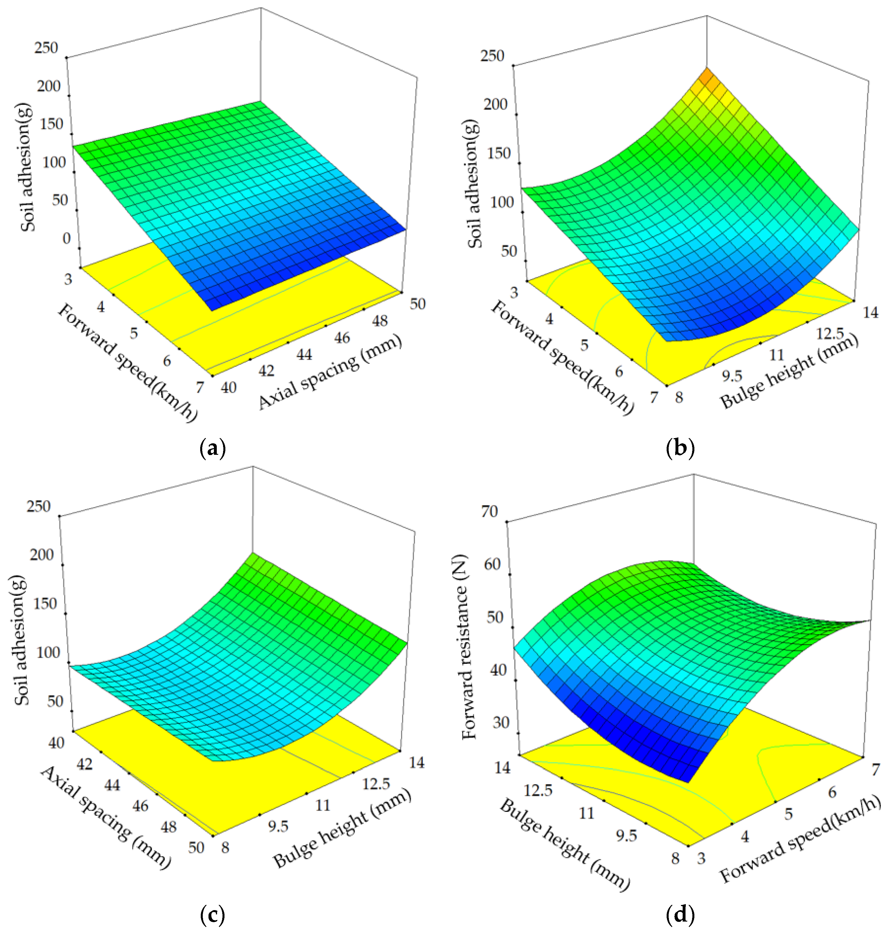
3.2. Analysis of the Response Surface

Figure 10 shows response surface of the significant interaction items in the Table 4 and Table 5. The approximately flat response surface in Figure 10a indicates there is a linear relationship between soil adhesion and the corresponding two factors. When the forward speed is large, the axial spacing increases without increasing the soil adhesion amount. When the forward speed is small, the soil adhesion decreases with the increase in the axial spacing. The influence of the forward speed on the soil adhesion is greater than that of the axial spacing. From Figure 10b, it can be seen that the influence of the bulge height on the soil adhesion is slightly greater than that of the forward speed, and the minimum value appears at the forward speed of 7 km/h and the bulge height of 45 mm. Figure 10c shows that when the bulge height is constant, when changing the axial spacing, the soil adhesion does not change significantly, which indicates that the axial spacing has little effect on the soil adhesion. When the bulge height is at a low level, the soil adhesion decreases with the increase in the bulge height. However, when the bulge height is at a high level, the soil adhesion decreases with the increase in the bulge height [25]. In Figure 10d shows when the forward speed is high, the response surface is relatively flat, whereas when the forward speed is low, the response surface drops sharply.

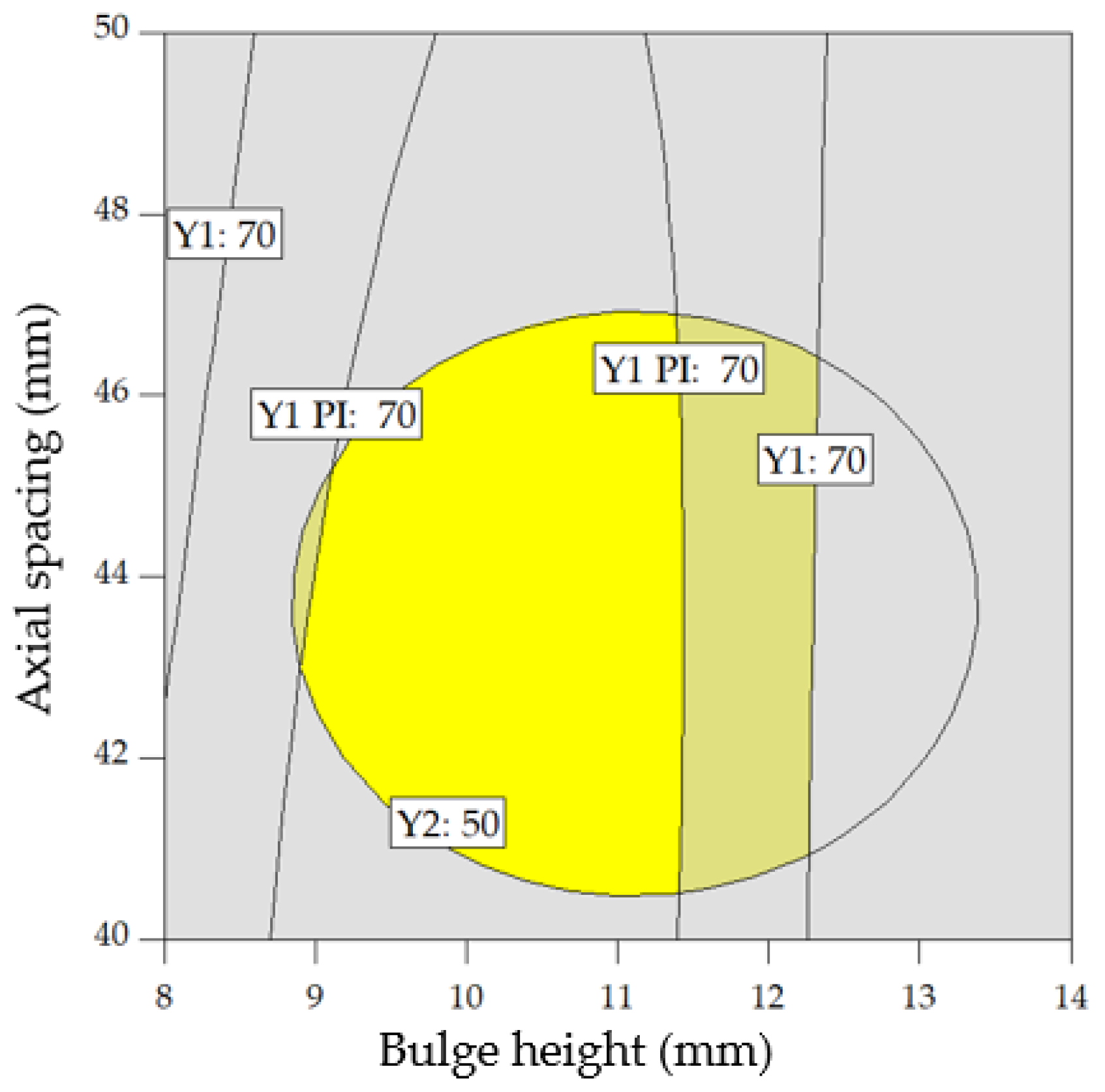
3.3. Parameter Combination Optimization

Under the constraint conditions of a forward speed of 3–7 km/h, an axial spacing of 40–50 mm, and a bulge height of 12–16 mm, the minimum value of the soil adhesion and the forward resistance is the target value. The objective function and constraint conditions are as follows:
min   ( Y 1 , Y 2 ) s . t . 3   k m / h x 1 7   k m / h 40   mm x 2 50   mm 8   mm x 3 14   mm
The optimization was conducted under the condition of a forward speed of 7 km/h. The multi-objective optimization solution was obtained using the optimization module of Design-Expert 10.0.4 software (Stat-Ease Inc., Minneapolis, MN, USA). The optimization results are displayed in Figure 11. The optimized parameters were selected as follows: a forward speed of 7 km/h, an axial spacing of 40.7–46.8 mm, and a bulge height of 9.3–11.5 mm, where the soil adhesion is less than 70 g and the forward resistance is less than 50 N.

4. Discussion

According to the above results for the methods and applications of surface modification and viscosity reduction, modifying the geometric parameters of the smooth press roller could improve its working performance. In the pre-experiment, the spherical convex hull arranged on the surface of the press roller improved the working performance of the smooth press roller. Based on the spherical convex hull, we screened the geometric line type (lemniscate curve) with the ability to reduce viscosity and resistance, and mapped the design according to the line shape and the base circle. In addition, the convex hull structures were arranged on the surface of the smooth press roller according to the spiral arrangement scheme. In this way, a press roller with a lemniscate curve geometry is capable of reducing the viscosity and resistance.
The amount of soil adhesion of press roller developed by Wang et al. [11] is 38.9–108.4 g, and Tong et al. [7] is 63–140 g. In this paper, the soil adhesion of the new designed press roller is 54–213 g, which is similar to other literature results. The forward resistance of press roller developed by Wang et al. [11] is 23.27–196.85 N, and the forward resistance of the new designed press roller is 38.6–65.3 N. From the perspective of index order of magnitude, the experimental results in this paper are basically consistent with the existing literature. The above results shows that although the amount of soil adhesion varies with soil conditions and operating parameters for the press roller of the seeder, the value is generally within a certain range.
During the compaction process, the wear of press roller is caused by soil particles, which is inevitable. Wear is one of the three major problems encountered by the press roller. The EDEM software has the ability to study the wear of press roller. In this paper, to ensure that the press roller could rotate 2–3 times, the square virtual soil bin was established, which is suitable for studying soil adhesion. In general, the degree of wear increases as the working time increases. If the above soil bin was used to study wear, the degree of wear would be insufficient. Generally, the annular soil bin could realize the uninterrupted and long-term operation of the press roller. Thus, the established annular virtual soil bin is a prerequisite for the study wear. In addition, selecting the relative wear model is also indispensable. If that is the case, the distribution and law of wear on the surface of the designed press roller will be studied, which could improve working efficiency and reduce working costs [29,30].

5. Conclusions

In this research, based on the geometric characteristics of a lemniscate curve revolver, a new non-smooth press roller for seeder in Rice–Wheat Rotation was designed. By using the EDEM2020 software, we found that a Hertz–Mindlin with JKR contact model between the soil particles and the press roller is suitable for researching soil adhesion. The central-face composite response test scheme was used to test the performance of the newly designed press roller. The test results showed that the forward speed, axial spacing, and bulge height can significantly influence soil adhesion and forward resistance. Optimized parameters were selected as follows: a forward speed of 7 km/h, an axial spacing of 40.7–46.8 mm, and a bulge height of 9.3–11.5 mm, where the soil adhesion is less than 70 g and the forward resistance is less than 50 N.
For future research, firstly, under different soil conditions, the working performance of the press roller will be studied. For example, the soil moisture content will be selected as the experimental factor for exploring the relationship between soil moisture content and soil adhesion, based on the differences under the condition of soil moisture content over different years, time periods, and regions. Secondly, a DEM–MBD coupling simulation model of the interactions between the press device and the soil will be constructed, to investigate the unsteady motion of the press roller, and the formation mechanism of soil adhesion.

Author Contributions

Conceptualization, methodology, resources, formal analysis, investigation, validation, writing—original draft, data curation, and visualization, H.L. and W.Z.; supervision, W.Z. All authors have read and agreed to the published version of the manuscript.

Funding

This research was funded by the National Key Research and Development Program of China (Grant No. 2021YFD2000401), the Jiangsu Provincial Natural Science Foundation of China (Grant No. BK20211021), the Natural Science Foundation of Jiangsu Province (Grant No. BE2020319-5) and the Jiangsu Province Agricultural Science and Technology Independent Innovation Fund (Grant No. CX(21)3143).

Institutional Review Board Statement

Not applicable.

Informed Consent Statement

Not applicable.

Data Availability Statement

Not applicable.

Acknowledgments

The datasets used and/or analyzed during the current study are available from the corresponding author on reasonable request.

Conflicts of Interest

The authors declare that they have no competing interest.

References

  1. Wang, C.; Li, H.; He, J.; Wang, Q.; Lu, C.; Wang, J. Design and experiment of pneumatic wheat precision seed casting device in rice-wheat rotation areas. Trans. Chin. Soc. Eng. 2020, 51, 43–53. [Google Scholar]
  2. Qin, K.; Ding, W.; Fang, Z.; Du, T.; Zhao, S.; Wang, Z. Design and experiment of seeding system for harvest ditch and stalk disposing machine. Trans. Chin. Soc. Eng. 2017, 48, 54–62. [Google Scholar]
  3. Wang, C.; Li, H.; He, J.; Wang, Q.; Lu, C.; Yang, H. Optimization design of a pneumatic wheat-shooting device based on numerical simulation and field test in rice–wheat rotation areas. Agriculture 2022, 12, 56. [Google Scholar] [CrossRef]
  4. Lu, B.; Ni, X.; Li, S.; Li, K.; Qi, Q. Simulation and experimental study of a split high-speed precision seeding system. Agriculture 2022, 12, 1037. [Google Scholar] [CrossRef]
  5. Shi, Y.; Yu, H.; Jiang, Y.; Wang, X.; Chen, H.; Liu, H. Optimization of strip fertilization planter for straw throwing and paving. Agriculture 2022, 12, 613. [Google Scholar] [CrossRef]
  6. Han, L.; Yuan, W.; Yu, J.; Jin, J.; Xie, D.; Xi, X.; Zhang, Y.; Zhang, R. Simulation and experiment of spiral soil separation mechanism of compound planter based on discrete element method (DEM). Agriculture 2022, 12, 511. [Google Scholar] [CrossRef]
  7. Tong, J.; Zhang, Q.; Guo, L.; Chang, Y.; Guo, Y.; Zhu, F.; Chen, D.; Liu, X. Compaction performance of biomimetic press roller to soil. Biosys. Eng. 2015, 12, 152–159. [Google Scholar] [CrossRef]
  8. Aikins, K.A.; Jensen, T.A.; Antille, D.L.; Barr, J.B.; Ucgul, M.; Desbiolles, J.M.A. Evaluation of bentleg and straight narrow point openers in cohesive soil. Soil Tillage Res. 2021, 211, 105004. [Google Scholar] [CrossRef]
  9. Guo, H. Research and Experiment of Elastic Press Device for Inter-Row Till-Planter. Ph.D. Thesis, Jilin University, Changchun, China, 2014. [Google Scholar]
  10. Zhao, J. Research of Key Technology of No-Tillage Seeder for Stubble Retain with ALTERNATING Tillage. Ph.D. Thesis, Jilin University, Changchun, China, 2015. [Google Scholar]
  11. Wang, W. Bionic Press Device with Profiling Mechanism for Soybean Precision Planter. Ph.D. Thesis, Jilin University, Changchun, China, 2016. [Google Scholar]
  12. Chen, H.; Xu, Y.; Shi, N. Design and experiment on three-way adjustable V-type soil-covering and soil-compacting device. J. Northeast. Agric. Univ. 2018, 49, 65–73. [Google Scholar]
  13. Chang, Y. Bionic Soil Press Roller with Convex Geometrical Structure. Master’s Thesis, Jilin University, Changchun, China, 2014. [Google Scholar]
  14. Tong, J.; Zhang, Q.; Chang, Y.; Chen, D.; Dong, W.; Zhang, L. Reduction of soil adhesion and traction resistance of ridged bionic press rollers. Trans. Chin. Soc. Eng. 2014, 45, 135–140. [Google Scholar]
  15. Zhang, Z. Interaction of Soil and Rolling Soil Engaging Components for Micro-Topographical Preparation and Their Bionic Geometrical Structures. Ph.D. Thesis, Jilin University, Changchun, China, 2014. [Google Scholar]
  16. Wang, W. Research on Key Technologies of Constructing High-Quality Maize Seedbed and Its Inter-Row Till-Planter. Ph.D. Thesis, Jilin University, Changchun, China, 2019. [Google Scholar]
  17. Gong, H.; Chen, Y.; Wu, S.; Tang, Z.; Liu, C.; Wang, Z.; Fu, D.; Zhou, Y.; Qi, L. Simulation of canola seedling emergence dynamics under different soil compaction levels using the discrete element method (DEM). Soil Tillage Res. 2022, 223, 1037. [Google Scholar] [CrossRef]
  18. Jiang, M.; Dai, Y.; Cui, L.; Xi, B. Experimental and DEM analyses on wheel-soil interaction. J. Terramech. 2018, 76, 15–28. [Google Scholar] [CrossRef]
  19. Acquah, K.; Chen, Y. Discrete element modelling of soil compaction of a press-wheel. AgriEngineering 2021, 3, 278–293. [Google Scholar] [CrossRef]
  20. Khot, L.R.; Salokhe, V.M.; Jayasuriya, H.P.W.; Nakashima, H. Experimental validation of distinct element simulation for dynamic wheel-soil interaction. J. Terramech. 2007, 44, 429–437. [Google Scholar] [CrossRef]
  21. Czapla, T.; Pawlak, M. Simulation of the wheel-surface interaction dynamics for all-terrain vehicles. Appl. Mech. 2022, 3, 360–374. [Google Scholar] [CrossRef]
  22. Fu, J.; Zhang, Y.; Chen, Z.; Ren, L.; Cheng, C. Bionic design and experiment of threshing tooth based on structure of cattle apex tongue filiform papillae. Trans. Chin. Soc. Eng. 2019, 50, 167–176. [Google Scholar]
  23. Makange, N.R.; Ji, C.; Torotwa, I. Prediction of cutting forces and soil behavior with discrete element simulation. Comput. Electron. Agric. 2020, 179, 105848. [Google Scholar] [CrossRef]
  24. Meirion-Griffith, G.; Spenko, M. A Modified pressure-sinkage model for small, rigid wheels on deformable. Terrains. J. Terramech. 2011, 48, 149–155. [Google Scholar] [CrossRef]
  25. McKyes, E. Soil Cutting and Tillage. Dev. Agric. Eng. 1989, 10, 194–229. [Google Scholar]
  26. Ren, L. Soil Adhesion Mechanics; China Machine Press: Beijing, China, 2011. [Google Scholar]
  27. Vidal, M.; Bastos, D.; Silva, L.; Gaspar, D.; Paulo, I.; Matos, S.; Vieira, S.; Bordado, J.M.; Galhano dos Santos, R. Up-cycling tomato pomace by thermochemical liquefaction—A response surface methodology assessment. Biomass Bioenergy 2022, 156, 106324. [Google Scholar] [CrossRef]
  28. Mangili, I.; Lasagni, M.; Huang, K.; Isayev, A.I. Modeling and optimization of ultrasonic devulcanization using the response surface methodology based on central composite face-centered design. Chemom. Intell. Lab. Syst. 2015, 144, 1–10. [Google Scholar] [CrossRef]
  29. Cucinotta, F.; Scappaticci, L.; Sfravara, F.; Morelli, F.; Mariani, F.; Varani, M.; Mattetti, M. On the morphology of the abrasive wear on ploughshares by means of 3D scanning. Biosyst. Eng. 2019, 179, 117–125. [Google Scholar] [CrossRef]
  30. Wei, M.; Zhu, L.; Luo, F.; Zhang, J.-W.; Dong, X.-W.; Jen, T.-C. Share-soil interaction load and wear at various tillage conditions of a horizontally reversible plough. Comput. Electron. Agric. 2019, 162, 21–30. [Google Scholar] [CrossRef]
Figure 1. Structural diagrams of a wheat sowing unit with a non-smooth press roller. 1.Primary rotary tillage system. 2. Secondary rotary tillage system. 3. Press roller. 4. Fertilizer shovel. 5. Opener. 6. Soil cover. 7. Smooth roller. 8. Double kink convex hull geometry.
Agriculture 12 01599 g001
Figure 2. Mutual position diagram of circular arc-type edge line and soil. Note: a1 is the contact point between the base circle and the soil; a1 is the vertex corresponding to diagonal β1; a2 is the contact point between the contour curve and the base circle; a2 is the vertex corresponding to β2.
Agriculture 12 01599 g002
Figure 3. Lemniscate curve and base circle edge line diagram. Note: R is the base circle radius; a is the parametric equation coefficient; θ is the corresponding central angle theta; h is the bulge height.
Agriculture 12 01599 g003
Figure 4. Two-dimensional representation of convex geometrical structure on press roller.
Agriculture 12 01599 g004
Figure 5. Structure diagram of lemniscate curve type press roller. 1. Gray convex hull (bulge height 14 mm); 2. Pink convex hull (bulge height: 11 mm); 3. Blue convex hull (bulge height 8 mm); 4. The smooth press roller (diameter in mm).
Agriculture 12 01599 g005
Figure 6. EDEM simulation of angle of repose.
Agriculture 12 01599 g006
Figure 7. DEM model establishment and numerical simulation.
Agriculture 12 01599 g007
Figure 8. Soil dynamic process of the press roller.
Agriculture 12 01599 g008
Figure 9. Validation test platform and soil adhesion.
Agriculture 12 01599 g009
Figure 10. Response surfaces between factor interactions and indexes: (a) Y1 (x1,x2,11 mm); (b) Y2 (x1,45 mm,x3); (c) Y1 (5 km/h,x2,x3); (d) Y2 (x1,45 mm,x3).
Agriculture 12 01599 g010
Figure 11. Optimum analysis of parameters.
Agriculture 12 01599 g011
Table 1. Parameter table for microscopic discrete element method simulation.
ParameterSoilSteel
Poisson ratio0.30.25
Shear modulus (MPa)17.9 × 10⁴
Density (kg/m3)26007820
Contact mechanical
parameters
Static friction coefficientSoil-Soil0.3
Soil-Steel0.3
dynamic friction coefficientSoil-Soil0.1
Soil-Steel0.1
restitution coefficientSoil-Soil0.17
Soil-Steel0.15
surface energy (J/m2)Soil-Soil7
Soil-Steel3.2
Table 2. Experimental factors and levels for the central composite face-centered method.
LevelsFactors
Forward Speed x1 (km/h)Axial Spacing (mm)Bulge Height x3 (mm)
175014
054511
−13408
Table 3. Test schemes and results for the central composite face−centered method.
No.FactorsIndexes
x1x2x3Y1/gY2/N
1545119148.3
2545119747.7
3545119645.6
45451414756.7
5545810651.3
6550119854.7
7540119556.3
8745115447.8
93451112740.7
107501410258.7
113501418054.3
127401410755.7
133401421348.7
1475087465.3
15350812545.3
1674086950.7
17340812938.6
Table 4. Variance analysis of regression equation for soil adhesion.
SourceSum of SquaresDFMean SquareF Valuep ValueSignificant
Model24,787.692754.2114.6<0.0001***
x113,542.4113,542.4563.5<0.0001***
x2115.61115.64.810.0644*
x36051.616051.6251.8<0.0001***
x1x2171.11171.17.120.0321**
x1x3666.11666.127.70.0012***
x2x3190.11190.17.90.026**
x1240.8140.51.70.2354
x2211.9111.90.50.5034
x322762.912762.9114.9<0.0001***
Residual168.2724.03
Lack of Fit147.6529.52.90.2794
Pure Error20.7210.3
Total24,955.916
Note: “*” means relatively significant (0.05 < p < 0.1), “**” means significant (0.01 < p < 0.05), and “***” means highly significant (p < 0.01).
Table 5. Variance analysis of regression equation for forward resistance.
SourceSum of SquaresDFMean SquareF Valuep ValueSignificant
Model652.07972.456.820.0096**
x1256.041256.0424.110.0017***
x280.09180.097.540.0287**
x352.44152.444.940.0617*
x1x23.5113.510.330.5833
x1x353.56153.565.040.0596**
x2x320.16120.161.900.2107
x1289.65189.658.440.0228**
x2280.03180.037.540.0287
x3242.13142.133.970.0866*
Residual74.33710.62
Lack of Fit70.31514.067.000.1298
Pure Error4.0222.01
Total726.4016
Note: “*” means relatively significant (0.05 < p < 0.1), “**” means significant (0.01 < p < 0.05), and “***” means highly significant (p < 0.01).
Publisher’s Note: MDPI stays neutral with regard to jurisdictional claims in published maps and institutional affiliations.

