


Effects of Uplift Resistance on Continuous-Pipe-Foundation of Single-Span Plastic Greenhouse by Steel Plate Pipe Connector

Department of Agricultural and Rural Engineering, Chungbuk National University, Chungdea-ro 1, Seowon-Gu, Cheongju 26844, Chungbuk, Republic of Korea
Agriculture 2022, 12(12), 1998; https://doi.org/10.3390/agriculture12121998
Submission received: 28 September 2022
/
Revised: 20 November 2022
/
Accepted: 21 November 2022
/
Published: 24 November 2022
(This article belongs to the Special Issue Advances in Agricultural Engineering Technologies and Application)
Abstract
:The single-span plastic greenhouses are affected by strong winds which generate uplift resistance causing the bending of members, damage to protective films, and damage to crops. This study performed a field test using the static axial tensile load method to present basic data to prevent damage to a single-span plastic greenhouse. Three representative areas were selected, and the effects of pipe connectors, rafter spacing, and embedding depth were tested. In the field test results, it was found to be greatly affected by the pipe connector. The pull-out resistance at the site fixed by welding instead of the pipe connector was measured as 4.5 times the sliding resistance standard value of the Rural Development Administration. In other sites, the measurement was below the standard value of the sliding resistance of the pipe connector. It was confirmed that the uplift resistance is determined by the sliding resistance of the pipe connector, the rafters, and the crossbar pipe. Therefore, it seems possible to increase the uplift resistance of a single-span plastic greenhouses continuous foundation through the reinforcement of the pipe connector. The field test results can be utilized as basic data for the reinforcement of the commercialization of single-span plastic greenhouses and new standards.
1. Introduction
In Korea, from 1998 to 2015, the amount of damage to plastic houses due to wind resistance and heavy snowfall added up to KRW 76.7 billion annually, and the cumulative area of damage was 20.279 ha (about 40% of the total site) [1]. Single-span plastic greenhouses using galvanized steel pipes as rafter pipes accounted for 84.9% of the facility site [2].
The single-span plastic greenhouse industry for facility horticulture suffered economic losses in the early 2000s due to meteorological disasters such as heavy snow and strong winds. In order to reduce economic losses, MIFAFF and RDA (2014) released data such as snow depth and wind speed for July 2014 [3]. The main causes of damage to single-span plastic greenhouses were strong winds and heavy snowfall, and the damage caused by heavy rains weakens the ground supporting the structure, causing uplift or overturning damage when strong winds occur [4]. As of 2019, about 99% of all greenhouses were commercialized, and among them, single-span plastic greenhouses were predominantly used, accounting for 78.7% of the facility site [5].
The single-span plastic greenhouse is a lightweight structure that is very vulnerable to strong winds or heavy snow [6,7,8], with the damage caused by strong winds in 2019 accounting for 98% of the total damage, which is a serious level [9]. As of 2020, 91.8% of the damage to sites for single-span plastic greenhouses in private facilities was found to be caused by typhoons and strong winds [10]. However, the data on the uplift resistance of single-span plastic greenhouse foundations are insufficient [11,12]. In order to compensate for weak uplift resistance, a lot of effort is needed to build greenhouses with heavy foundations or that are made with concrete on site and backfilled with soil [13]. In addition, research on uplift resistance is steadily progressing, through indoor model tests on the type of foundation and depth of embedding [8,14,15,16,17,18,19,20,21].
The single-span plastic greenhouse presented in the anti-disaster design standards of the Ministry of Agriculture, Food and Rural Affairs (MAFRA) is intended to improve the uplift resistance or settlement. As for the design method, a continuous pipe foundation in the form of a purlin was installed at the midpoint (around 25 cm) of the embedded part of the rafter (40–50 cm) [3]. The connection between the rafter and the purlin was achieved using a pipe connector, forming a continuous pipe foundation that is embedded in the ground [4,11].
Yun et al. (2015) suggested a new pipe standard for the continuous pipe foundation because the pipe diameter and thickness had little effect on uplift resistance as a model test (Figure 1) [22]. In the greenhouse, lift is generated due to the pressure difference caused by the strong wind current, causing the foundation to be uplift-resistant and structural damage to the entire structure. The anti-disaster design standards of the Ministry of Agriculture, Food and Rural Affairs only formulate regulations for the sliding resistance, structural material and design strength (snow depth and wind speed) [3]. The pipe connector plays an important role in helping single-span plastic greenhouses withstand heavy snowfall and strong winds. Most farmers use single-span plastic greenhouses, so the performance of the pipe connector is important [23].
However, damage to a single-span plastic greenhouse may cause damage to the plastic used as a structural material. In these cases, plastic decomposes to microplastics through physical, chemical, and biological process [24]. The amount of plastic waste generated from plastic houses was 68,758 tons as of 2018, accounting for 21.6% of the total plastic waste [25]. However, the negative emissions caused by waste plastic is a source of pollution in rural and agricultural environments [26].
In order to minimize such secondary damage, it is necessary to prevent damage from strong winds in single-span plastic greenhouses, and for this, reinforcement measures for the pipe connector are essential.
Therefore, in this study, an in situ down-scaled model test was carried out on a continuous pipe foundation of the single-span plastic greenhouse. As a down-scaled model test object, the rafter and purlin are connected by a pipe connector of steel plate. In the field down-scaled model test, only one case was selected for each site, and the results were compared and evaluated by testing the installation direction and the presence or absence of the pipe connector differently.
2. Materials and Methods
2.1. Sample Preparation
The test sites where the characteristics of the embedded continuous pipe foundation of the single-span plastic greenhouse were identified are as follows: Cheongju, Chungcheongbuk-do (A), Jeonju, Jeollabuk-do (B), and Gyehwa, Jeollabuk-do (C). Site A is an agricultural high school practice site and is classified as SM according to the unified soil classification system (USCS). Site B is a clinical trial complex within the Rural Development Administration, which is classified as SC. Site C is an agricultural technology center located on reclaimed land and is classified as ML in the unified soil classification system. Table 1 shows the physical and mechanical properties of soil by the site. Characteristics are classified by USCS and USDA: SM is silty sand, loamy sand; SC is clayey sand, sandy loam, and ML is silt, sandy loam. Gs is the specific gravity and refers to the ratio of the weight of soil in the air to the weight of distilled water of the same volume. LL is the liquid limit, and it refers to the water content at the boundary where soil is mixed with water to change to a liquid state and a plastic state. PI is the water content at the boundary where the soil changes from a semi-solid state to a solid state. It is used to determine the physical condition of the soil. The is the unit weight and refers to the value obtained by dividing the weight of the soil mass by the corresponding volume. It is the weight ratio of soil per unit volume. The firmness and looseness of the ground can be determined. O.M.C is the water content corresponding to the maximum unit weight.
2.2. Field Test Condition
The continuous pipe foundation embedded in the ground of the single-span plastic greenhouse is composed of rafter and purlin. Rafter and purlin are embedded in the ground and are connected together with a pipe connector.
The pipe connector connects two members together by binding parts composed of a steel wire and a plate shape. In the field, cost and testing sites were limited, so only some parts of the rafter (column) and continuous pipe foundation were modeled. For the rafter and purlin used in the field test, galvanized steel pipes, as suggested in the anti-disaster design standards of the Rural Development Administration, were used. The rafter used in the test has a diameter of 31.8 mm, and the purlin has a diameter of 25.4 mm (Figure 2).
In the anti-disaster design standards of the Rural Development Administration, a total of 19 types of single-span plastic greenhouses are classified. The specifications of the rafter and the purlin are the same, and the spacing of the rafter and the embedded depth of the continuous pipe foundation are presented in Table 2.
The spacing of the rafter and the embedded depth of the continuous pipe foundation suggested in the field test were determined by referring to the anti-disaster design standards of the Rural Development Administration. Rafter spacing widely used by the Rural Development Administration at a standard of 500 mm, so the spacing was set to 500 mm, 600 mm, and 700 mm. The depths of the continuous pipe foundation were increased to 300 mm, 400 mm, and 500 mm by increasing the depth more than the standard because strong wind damage was occurring. As a test condition for each site, the rafter and continuous pipe foundation were welded in site A, and the pipe connector was connected in the rafter (vertical) direction in site B. In the site C, the pipe connector was connected in the crossbar (horizontal) direction.
2.3. Field Test Method
In order to classify the conditions of the field uplift resistance test, the first and English symbols indicate the site, the second number the embedded depth, and the third the rafter spacing (Table 3). The uplift resistance test method is based on JSF 1821 and ASTM D 3689-07 [28,29]. In this study, ASTM D 3689-07 standards were applied. This is a test method using the static axial tensile load of ASTM D 3689-07. The uplift resistance test was performed by increasing the load step by step by 5% to the estimated failure load. The step-by-step measurements were taken until the settlement gauge did not change and the load was maintained for at least 4 min to 15 min. The field test method using the axial tensile load control method is shown in Figure 3. The hydraulic load gauge used for the test was 50 kN, and the amount of settlement was measured up until 100 mm displacement. The area of the load plate was 0.08 m2.
2.4. Measured Uplift Resistance
3. Results
3.1. Results of Field Compaction on Site A, Site B, and Site C
Before the axial tensile load test, a field density test (Figure 8) was performed to determine the density of the original ground. The field density was compared with the density of the ground measured before the field axial tensile load test. Table 4 summarizes the field density results after 24 h of being embedded in the continuous pipe foundation in the test site. In site A, the average values were 12.84 kN/m3, 13.62 kN/m3, and 13.99 kN/m3 by each measure station. In site B, the average values were 11.10 kN/m3, 11.05 kN/m3, and 12.70 kN/m3 by each measure station. In site C, the average values were 12.96 kN/m3, 17.53 kN/m3, and 16.77 kN/m3 by each measure station. The deviation of the field density was the smallest in site A, and it was found to be smaller than the field density measured before the test of 13.56 kN/m3. Site B was found to be smaller than the measured field density of 12.45 kN/m3 before the test. Site C showed the largest variation in field density by each measure station and was found to be larger than the field density of 10.53 kN/m3 before the test. The differences in field density in site A, site B, and site C are thought to be due to the narrow width of the backfill excavation and the failure to compact the floor. In addition, site C is reclaimed and has high groundwater. Due to the high groundwater level, excess pore water pressure occurred during compaction, so the load was not evenly distributed during compaction, and the soil was not evenly spread out, so the field density was also different at these locations. It seems that it was not possible to allow sufficient time for the ground to be stabilized after installing the continuous pipe foundation.
3.2. Results of Field Test of Uplift Resistance on Site A, Site B, and Site C
The results of the static axial tensile load test by site A, site B, and site C are shown in Figure 9, Figure 10 and Figure 11. Processing the static axial tensile load test, when the uplift load increased, the rafters rose vertically and the load plate on the ground settlement. It was observed that the settlement of the load plate on the ground increased linearly as the load increased. As for the uplift loading stage, as described in the test method, the expected load was divided into five stages, and the degree of settlement was observed during uplift loading. In order to determine the yield point due to the destruction of the ground as the uplift load increases, an inflection point must occur in the load–settlement curve, but it increased linearly at all three sites.
Lee et al. (2014) reported that the maximum strength of the pipe connector was achieved upon the initial displacement in sliding resistance tests in the rafter and purlin directions and maintained a strength equivalent to 75% of the maximum strength up to 20.0 mm [33]. In addition, it was said that the influence of the test results on compaction management could not be ignored. In this study, after the settlement of up to 20.0 mm, the degree of settlement due to the increase in the load decreased. It maintains this strength of up to 20 mm, and it has been shown that there is little change in the degree of settlement due to an increase in load.
The reason why the inflection point was not found when assessing the relationship between the load and settlement is thought to be as follows: In site A, there is no purlin at the top of the ground. Therefore, the rafter was fixed and lifted directly. When the rafter was uplifted, the uplift load was transferred to the left and right rafters, and the ground surface was destroyed (Figure 12a). The destruction of the ground does not appear to cause an increase in the load and settlement. In site B and site C, bending deformation occurred due to the uplift load of the crosspiece (Figure 12b). After the bending deformation occurred, the fixed part of the pipe connector slid, and the bending deformation increased (Figure 12c).
The sliding resistance limit of the pipe connector is 1360 N, which is suggested in the anti-disaster design standards for special agricultural and horticultural facilities [3]. The settlement amount increased significantly from the uplift load of 2.9 kN in site A, 1.8 kN in site B, and 0.9 kN in site C. As the uplift load increased, the pipe connector slipped at the connection between the rafter and the purlin pipe. As a result, settlement of the ground did not occur. For this reason, it is unlikely that an inflection point due to an increase in uplift load will occur.
Table 5 summarizes the uplift resistance test results by site A, site B, and site C. The ultimate stress and yield stress were in the order of site A > site B > site C. There was no difference in yield stress due to the effect of embedded depth. In addition, rafter spacing did not affect yield stress. This is believed to be caused by the sliding of the pipe connector. Faizi et al. (2014) stated that the maximum uplift resistance of an embedded pipe is affected by the embedded depth [34]. However, in this study, it was found that the depth of embedding and the rafter spacing had no effect on the uplift resistance due to the sliding of the pipe connector.
3.3. Results of Uplift Resistance by Embedded Depth
The magnitudes of the uplift resistance for the embedded depth and the rafter spacing were compared (Figure 13 and Figure 14). There was a difference in the size of the embedded depth due to the influence of the pipe connector by site A, site B, and site C, but there was no difference in the trend. The same results were also obtained for the distance between the rafters. The difference in yield stress could not be explained, regardless of the connecting direction of the rafter and purlin and whether they were installed or not. In the field test using the static axial tensile load control method, it is necessary to determine the point where the yield stress occurs due to the sudden subsidence of the ground, the same as in the plate load test method. However, the sliding resistance of the pipe connector reduces the increase in load and settling. Wu et al. (2019) stated that the pipe diameter is independent of the failure mechanism and the maximum uplift resistance has no effect on the outcome [35]. This means that the diameter of the pipe does not affect the test results. In addition, it was difficult to determine the effect on the rafter spacing and embedding depth in this test, so we tried to compare these values with other data. However, there was no field test study on pipe connectors, so comparisons could not be made.
3.4. Discussion of Test Results for Site A, Site B, and Site C
The uplift resistance values of each test site, as determined using the field test, were compared. The uplift resistance was converted into a load and compared with the design standards of the Rural Development Administration. Considering the fact that the maximum uplift resistance is related to the sliding resistance of the pipe connector in the field test, the ultimate and yield stress was rearranged as a load, as shown in Table 6 and Figure 15. The uplift resistance by the test conditions showed a significant deviation in the order of A (1027.4) > B (999.5) > C (465.5). The uplift resistance showed a considerable variation in all three sites. Site A showed an average yield load of 6483.4 N, site B showed an average yield load of 1780.2 N, and site C showed an average yield load of 1176.8 N. It can be observed that the yield load does not satisfy the sliding resistance limit of the Rural Development Administration in site C. Site B also showed similar results to the slip resistance limit. The load-bearing capacity of a single-span plastic greenhouse varies greatly depending on the type of pipe connector. Experts assert that the pipe connector plays a central role in resistance to heavy snow and strong winds. However, the risk of damage to single-span plastic greenhouses is further increased by using pipe connectors with lower standard values than the standard pipe connectors suggested by the RDA [36].
Lee et al. (2014) reported that they did not meet the Rural Development Administration standard as a result of testing the same product as the aperture used in this study with different connecting directions [21]. In the field displacement control test results (Table 7) of Yun et al. (2015), it was reported that there are differences caused by the type of pipe connector [23]. In another recent study, we attempted to compare field uplift resistance results with soil box test results. However, they could not be compared because different test conditions were used with regard to the continuous pipe foundation.
In this study, it was found that the uplift resistance had no effect on the spacing and embedded depth of the rafter and purlin. The ultimate uplift resistance for the steel plate connector of Yun et al. (2015) was compared with the results of this study. The comparison results showed a significant difference of 507.99% increase at the site, 118.26% increase at the site B, and 8.52% increase at the site C. As shown in Figure 16, this can explain the cause of error between the results in the difference in field test conditions.
However, it was found that the sliding resistance of the steel plate pipe connector affects the uplift resistance. As reported by previous researchers, the connecting method for each type of pipe connector is important, and improving the sliding resistance of the pipe connector can reduce damage from strong winds in single-span plastic greenhouses. Therefore, in order to reduce the damage caused by strong winds, it seems necessary to increase the sliding resistance limit of the rafter and purlin.
4. Conclusions
In this study, field tests of uplift resistance were performed on a continuous pipe foundation of a single-span plastic greenhouse according to the connection direction of the pipe connector and whether or not it was used. The ability of the pipe connector was evaluated by measuring the uplift resistance of the continuous pipe foundation using a static axial tensile load test.
The backfill conditions of the field ground were smaller in site A and site B than the field density of the undisturbed ground, but site C was highly compacted. However, the uplift resistance measured by the static axial tensile load test was found to be the smallest in site C. This seems to be because the time allowed for the stabilization of the backfill ground was insufficient, and it was difficult to reproduce the field test. It was found that the uplift resistance for site A, site B, and site C did not show an inflection point in the load–settlement curve due to the influence of the pipe connector. It can be observed that the uplift resistance due to the difference between the spacing of the rafter and the embedded depth of the continuous pipe foundation was not affected. Additionally, the sliding resistance of the pipe connector was dominantly acting on the uplift resistance. The reason is that the pipe connection of site A was welded, so the slip resistance value of the pipe connector was measured 4.5 times higher than the value suggested by the Rural Development Administration design standard. Therefore, it seems that the damage to the single-span plastic greenhouse caused by strong winds can be reduced by supplementing the pipe connector. Additionally, obviously, sustainable agriculture will be possible by establishing reinforcement measures for 99% of single-span greenhouses commercialized in Korea. It seems that related organizations can use these data as a sliding resistance standard of the pipe connector.
Funding
This research received no funding.
Institutional Review Board Statement
Not applicable.
Data Availability Statement
The data used to support the findings of this study are included within the article.
Conflicts of Interest
The authors declare that they have no conflict of interest.
References
- RDA. Development of Foundation Design Technology on Single Span Plastic Greenhouse According to Soil Property; Rural Development Administration: Jeonju, Korea, 2021. (In Korean) [Google Scholar]
- Ministry of Agriculture, Food and Rural Affairs (MAFRA). Present Condition of Vegetable Grown in Facilities and Vegetable Production Performance; Ministry of Agriculture, Food and Rural Affairs: Sejong City, Korea, 2018. (In Korean)
- Ministry for Food, Agriculture, Forestry and Fisheries (MIFAFF); Rural Development Administration (RDA). Designated Notice of Standards to Endure Disaster for Horticultural and Special Facilities; MIFAFF & RDA: Gwacheon and Suwon, Korea, 2014. (In Korean) [Google Scholar]
- Rural Development Administration (RDA). Symposium for Reducing of Meteorological Disasters of Agricultural Facilities; RDA: Suwon, Korea, 2007; pp. 160–161. (In Korean) [Google Scholar]
- MAFRA, Facility Vegetable Greenhouse Status and Vegetable Production Output Report, Ministry of Agriculture, Food and Rural Affairs. 2021, pp. 105–108. Available online: 2020%20%EC%8B%9C%EC%84%A4%EC%B1%84%EC%86%8C%20%EC%98%A8%EC%8B%A4%ED%98%84%ED%99%A9%20%EB%B0%8F%20%EC%B1%84%EC%86%8C%EB%A5%98%20%EC%83%9D%EC%82%B0%EC%8B%A4%EC%A0%81.pdf (accessed on 15 September 2022). (In Korean).
- Robertson, A.; Roux, P.; Gratraud, J.; Scarascia Mugnozza, G.; Castellano, S.; Dufresne de Virel, M.; Palier, P. Wind pressures on permeably and impermeably clad structures. J. Wind. Eng. Ind. Aerodyn. 2002, 90, 461–474. [Google Scholar] [CrossRef]
- Lee, S.G.; Lee, J.W.; Lee, H.W. Development of One-Span Vinyl House for Reduction of Damage by Heavy Snow. J. Bio-Environ. Control 2005, 14, 138–144. (In Korean) [Google Scholar]
- Lee, B.G.; Yun, S.W.; Choi, M.K.; Lee, S.Y.; Moon, S.D.; Yu, C.; Yoon, Y.C. Uplift Bearing Capacity of Spiral Steel Peg for the Single Span Greenhouse. J. Bio-Environ. Control 2014, 23, 109–115. (In Korean) [Google Scholar] [CrossRef]
- Lee, W.-G.; Woo, J.-H.; Lee, H.-D.; Shin, K.-J. Analysis of Uplift Capacity on Single-span Greenhouse’s Foundation According to Wind Load and Evaluation for Reinforcing Methods. J. Archit. Inst. Korea 2022, 24, 33–39. (In Korean) [Google Scholar]
- MOIS. Statistical Year Book; Ministry of the Interior and Safety: Sejong City, Korea, 2021. (In Korean)
- Ogawa, H.; Tsuge, I.; Sato, Y.; Hoshiba, S.; Yamashita, S. Experimental analysis on strength of pipe—House with Ground anchoring (II). J. Soc. Agric. Struct. 1990, 20, 262–269. [Google Scholar]
- RDA; NAAS; Department of Agricultural Engineering. Guide Book for Reduction of Meteorological Disaster of Agricultural Facilities; Rural Development Administration National Institute of Agricultural Sciences: Wanju-gun, Korea, 2007. (In Korean) [Google Scholar]
- Tanaka, H.; Fujikawa, M.; Matsuzaki, T.; Sumikawa, O.; Daikoku, M.; Inooku, K. Application of a screw type pile for the foundation of greenhouse. Misc. Pub. NARO. West. Reg. Agric. Res. Cent. 2005, 3, 21–37. [Google Scholar]
- Kim, M.K.; Nam, S.W.; Son, J.E.; Yun, N.K. Analyses of actual state and structural safety of regionally characterized greenhouse in Korean. Prot. Hortic. Plant Fact. 1994, 3, 128–135. (In Korean) [Google Scholar]
- Kim, M.K.; Nam, S.W. Experimental studies on the structural safety of pipe-houses. Prot. Hortic. Plant Fact. 1995, 4, 17–24. (In Korean) [Google Scholar]
- Cho, Y.S.; Kwon, O.Y. Uplift Capacity of a Single Screw Anchor. KSCE J. Civ. Eng. 1997, 17, 275–283. (In Korean) [Google Scholar]
- Lee, B.J.; Lee, J.K. A study on the critical embedment ratio of screw anchors. J. Ind. Sci. 1999, 6, 475–492. (In Korean) [Google Scholar]
- Yoon, Y.C.; Suh, W.M.; Cho, J.H. The uplift capacity of plane and corrugated piles for pipe frame greenhouse. Prot. Hortic. Plant Fact. 2001, 10, 148–154. (In Korean) [Google Scholar]
- Yoon, Y.C.; Lee, K.H.; Yu, C. A study on the uplift capacity improvement of pipe-framed greenhouse foundation using circular horizontal anchors. KCID J. 2003, 10, 55–61. (In Korean) [Google Scholar]
- Kim, D.H.; Yoo, C.S. Pull-out capacity of screw anchor pile in sand using reduced-scale model tests. J. KGS. 2013, 29, 121–133. (In Korean) [Google Scholar]
- Choi, M.K.; Yun, S.W.; Kim, H.N.; Lee, S.Y.; Kang, D.H.; Yoon., Y.C. Uplift capacity of spiral bar through the model experiment. Prot. Hortic. Plant Fact. 2015, 24, 202–209. (In Korean) [Google Scholar] [CrossRef]
- Yun, S.W.; Choi, M.K.; Lee, S.Y.; Yoon, Y.C. Uplift capacity of meteorological disaster. J. Agric. Life Sci. 2015, 49, 303–310. (In Korean) [Google Scholar] [CrossRef]
- Song, H.S.; Lim, S.Y.; Ryu, H.R. Slip-Resistance Test for Plastic Greenhouse Pipe Connectors According to Loading Rate. In Proceedings of the Korean Society of Agricultural Engineers Conference, Daejeon, Korea, 20 October 2016. [Google Scholar]
- Ding, L.; Zhang, S.; Wang, X.; Yang, X.; Zhang, C.; Qi, Y.; Guo, X. The occurrence and distribution characteristics of microplastics in the agricultural soils of Shaanxi Province in north-western China. Sci. Total Environ. 2020, 720, 137525. [Google Scholar] [CrossRef]
- Korean Statistics Information Service, Production of Agricultural Waste Vinyl 2004–2020, Last Modified 03-282020. 2020. Available online: https://kosis.kr/statHtml/statHtml.do?orgId=392&tblId=DT_AGRI01&vw_cd=MT_ZTITLE&list_id=T_20&seqNo=&lang_mode=ko&language=kor&obj_var_id=&itm_id=&conn_path=MT_ZTITLE (accessed on 15 September 2022). (In Korean).
- Heo, J.; Knag, C.Y.; Kim, D.W.; Kim, N.Y.; Gi, Y. Public Promotion Measures on the Adequate Disposal of Waste Agricultural Plastics and Collection Enhancement; Korea Rural Economic Iistitute: Naju-si, Korea, 2002. (In Korean) [Google Scholar]
- Lee, S.G. Development of Small Scale Vinyl House Model for Reduction of Damage by Wind and Show; National Research Foundation of Korea: Taejon-jikhalsi, Korea, 2004. (In Korean) [Google Scholar]
- JS F 1821; Uplift Load Testing Method of Piles. Japanese Society of Soil Mechanics and Foundation Engineering. The Japanese Society of Soil Mechanics and Foundation Engineering. National Research Foundation of Korea: Taejon-jikhalsi, Korea, 1992; pp. 1821–1989.
- ASTM D 3689-07; Standard Test Methods for Deep Foundations under Static Axial Tensile Load. ASTM International: West Conshohocken, PA, USA, 2010.
- Butler, H.D.; Hoy, H.E. User’s Manual for the Texas Quick-Load Method for Foundation Load Testing; FHWA-IP-77-8; FHWA: Washington, DC, USA, 1997.
- FHWA. Design and Construction of Driven Pile Foundations. Workshop Manual; National Highway Institute: Arlington, VA, USA, 1997; Volumes I, FHWA-HI-97-013. [Google Scholar]
- AbdelSalam, S.S.; Anwar, M.B.; Esmail, D.I. LRFD for Shallow Foundations Using Plate Load Test Data; Geo-Congress: Minneapolis, MN, USA, 2020; pp. 1–11. [Google Scholar]
- Lee, S.H.; Shin, K.J. Slip Test of Pipe Connector for Greenhouse Frame. J. Archit. Inst. Korea Struct. Constr. 2014, 30, 9–17. (In Korean) [Google Scholar] [CrossRef]
- Faizi, K.; Jahed Armaghani, D.; Momeni, E.; Nazir, R.; Mohamad, E.T. Uplift Resistance of Buried Pipelines Enhanced by geogrid. Soil Mech. Found. Eng. 2014, 51, 188–195. [Google Scholar] [CrossRef]
- Wu, J.; Kouretzisa, G.; Suwala, L.; Ansaria, Y.; Scott, W.S. Shallow and deep failure mechanisms during uplift and lateral dragging of buried pipes in sand. Can. Geotech. J. 2019, 27, 1–17. [Google Scholar] [CrossRef]
- Lee, S.I. The Farmers Newspaper. 2013. Available online: https://www.nongmin.com/plan/PLN/SRS/77249/view (accessed on 16 November 2022).
Figure 1.
Case of foundation damage of single-span plastic greenhouse [27].
Figure 1.
Case of foundation damage of single-span plastic greenhouse [27].

Figure 2.
Construction materials for testing: (a) test pipe and pipe connector; (b) horizontal pipe connector; (c) vertical pipe connector.
Figure 2.
Construction materials for testing: (a) test pipe and pipe connector; (b) horizontal pipe connector; (c) vertical pipe connector.
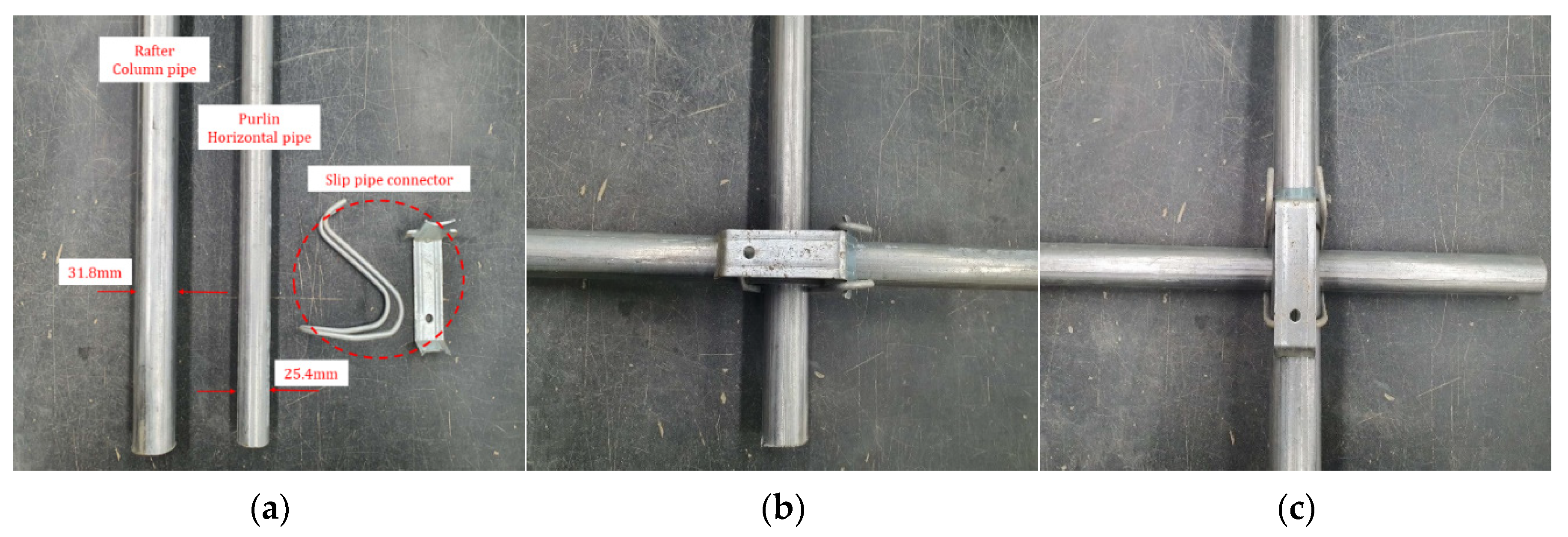
Figure 3.
Field static axial tensile load test: (a) installed continuous foundation of site A and (b) installed continuous foundation of site B and site C.
Figure 3.
Field static axial tensile load test: (a) installed continuous foundation of site A and (b) installed continuous foundation of site B and site C.
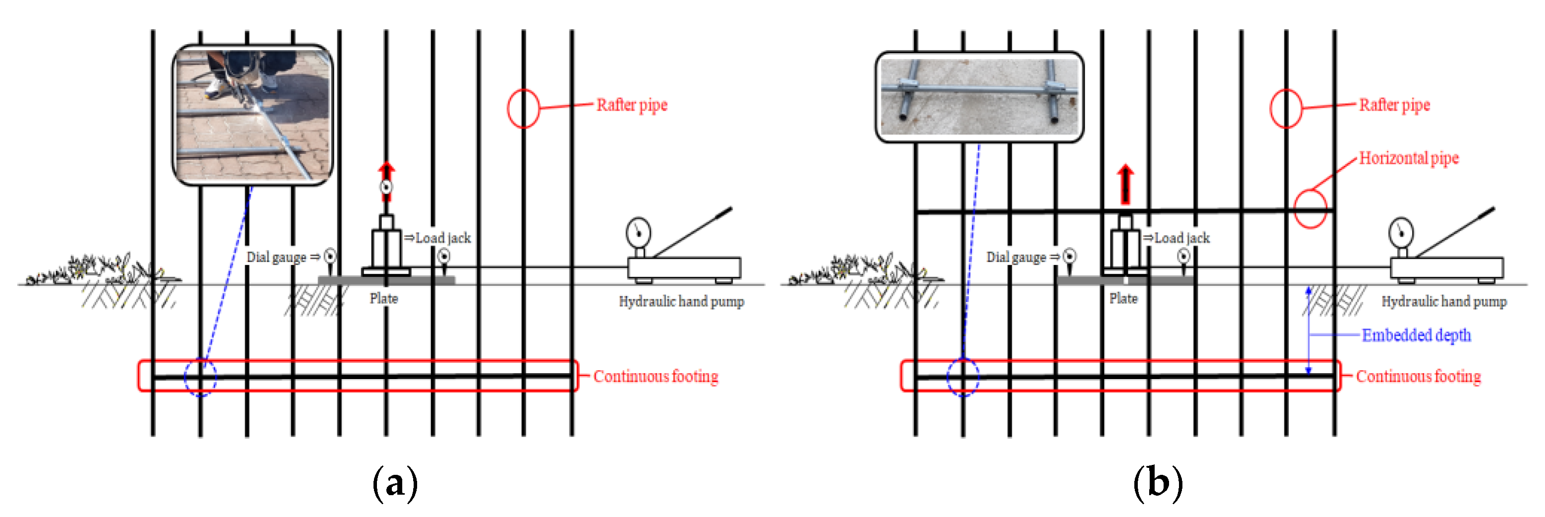
Figure 4.
Field test procedure of site A: (a) ground grading work; (b) embedded depth leveling; (c) uplift testing of continuous foundations.
Figure 4.
Field test procedure of site A: (a) ground grading work; (b) embedded depth leveling; (c) uplift testing of continuous foundations.
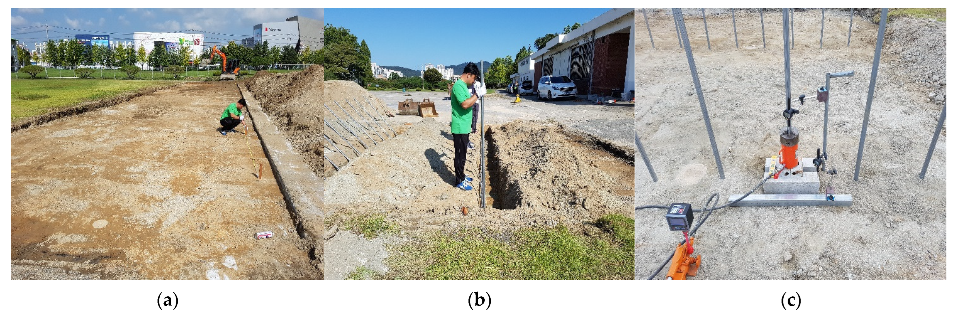
Figure 5.
Field test procedure of site B: (a) ground grading work; (b) embedded depth leveling; (c) uplift testing of continuous foundations.
Figure 5.
Field test procedure of site B: (a) ground grading work; (b) embedded depth leveling; (c) uplift testing of continuous foundations.
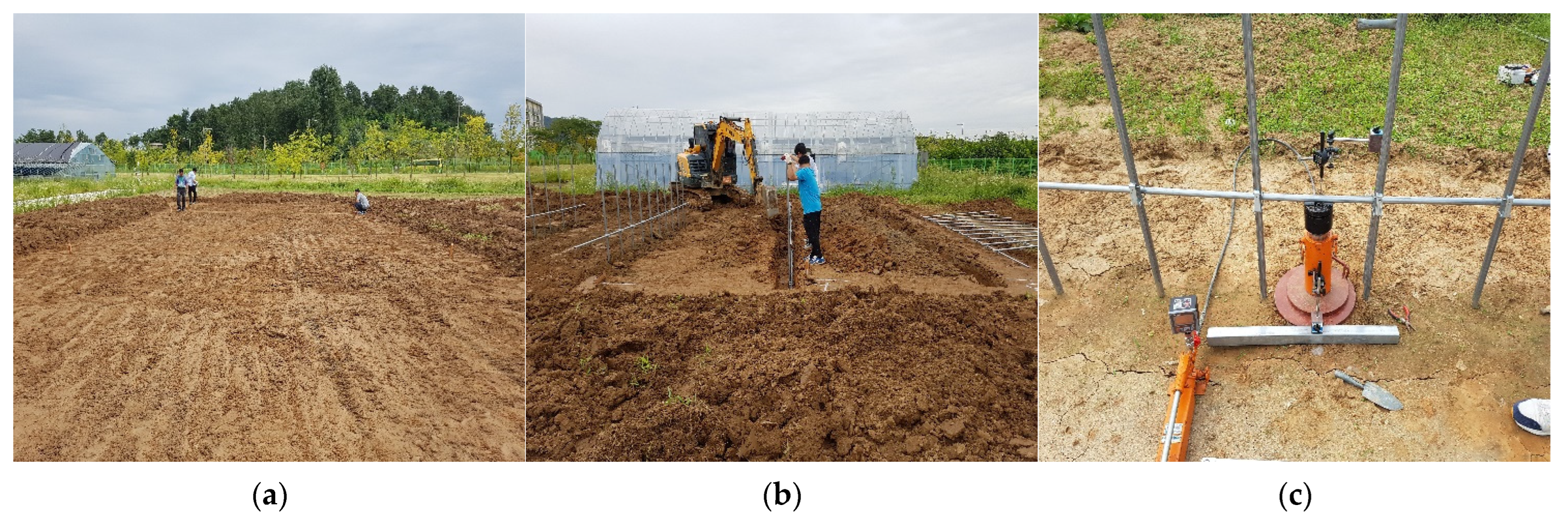
Figure 6.
Field test procedure of site C: (a) ground grading work; (b) embedded depth leveling; (c) uplift testing of continuous foundations.
Figure 6.
Field test procedure of site C: (a) ground grading work; (b) embedded depth leveling; (c) uplift testing of continuous foundations.
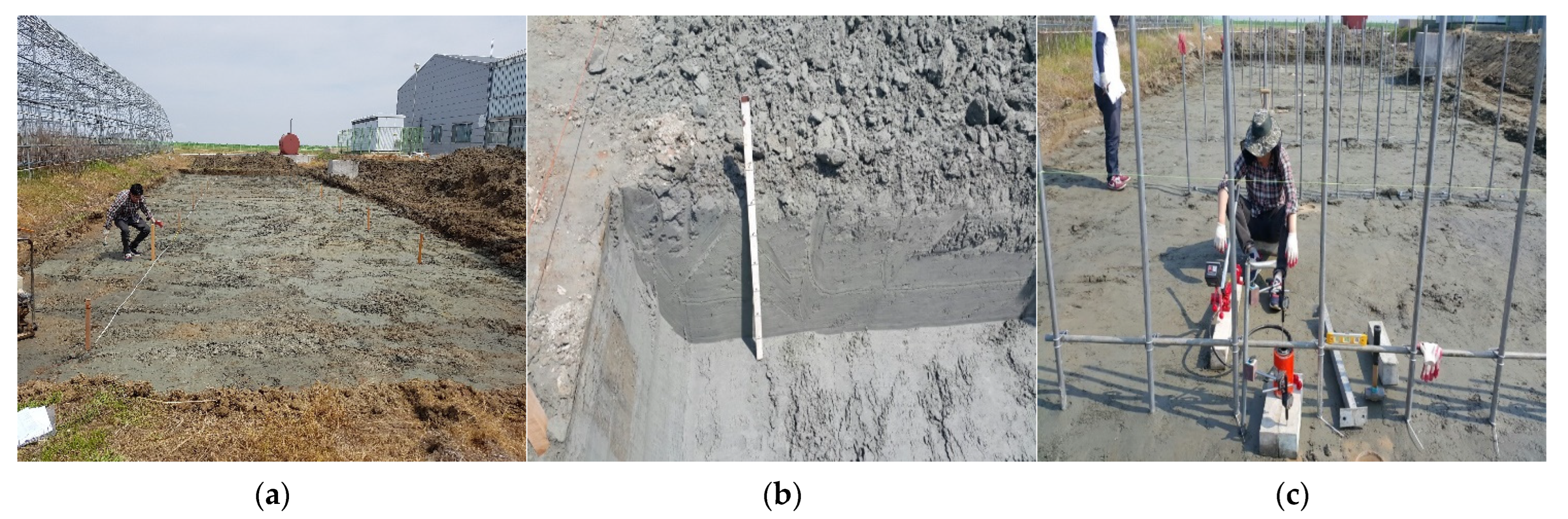
Figure 7.
Load–settlement curve from PLT: (a) shape of curvature and (b) log-log plot (AbdelSalam et al., 2020).
Figure 7.
Load–settlement curve from PLT: (a) shape of curvature and (b) log-log plot (AbdelSalam et al., 2020).
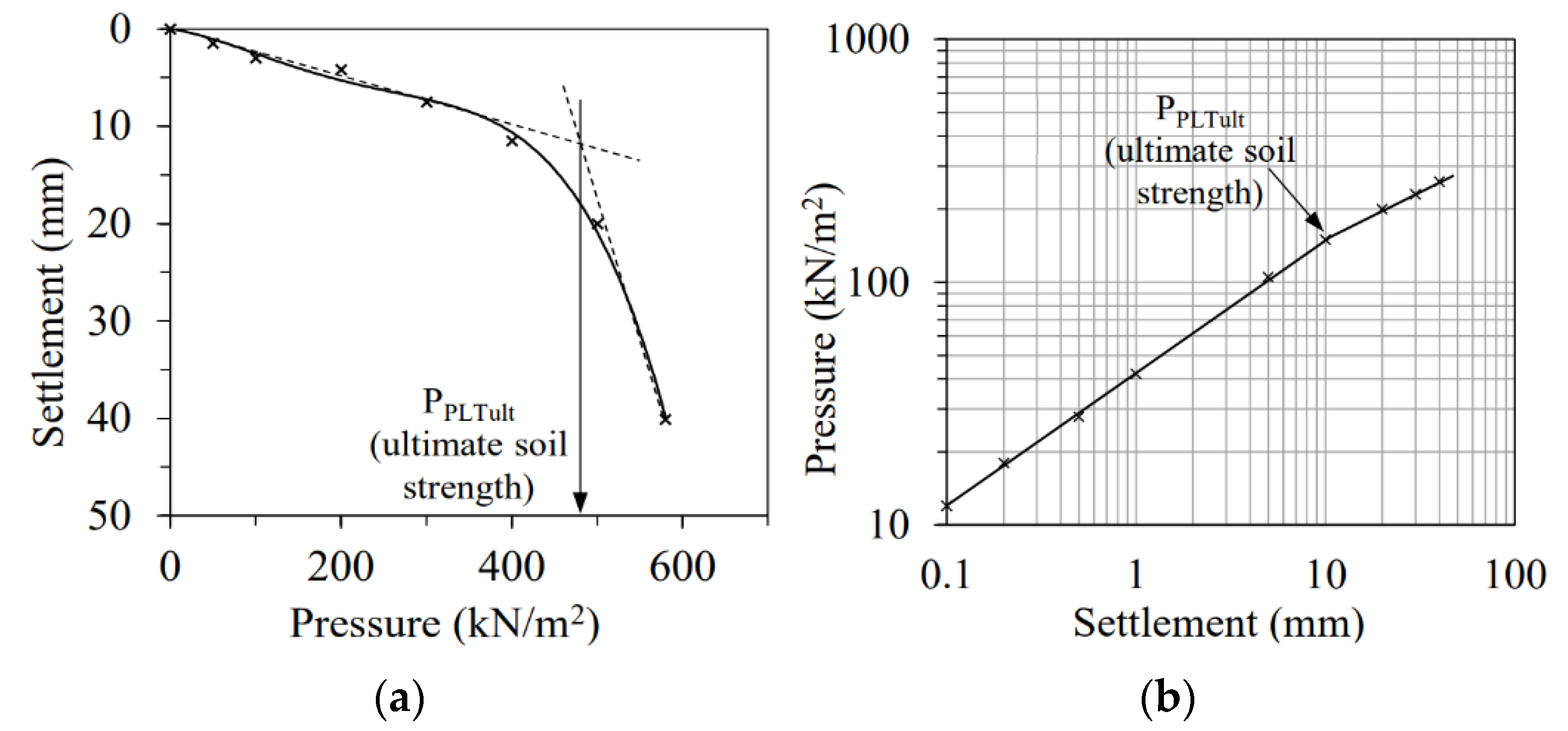
Figure 8.
Field dry unit weight of soils. (a) field dry unit weight test; (b) results of field dry unit weight for site A, site B, and site C.
Figure 8.
Field dry unit weight of soils. (a) field dry unit weight test; (b) results of field dry unit weight for site A, site B, and site C.
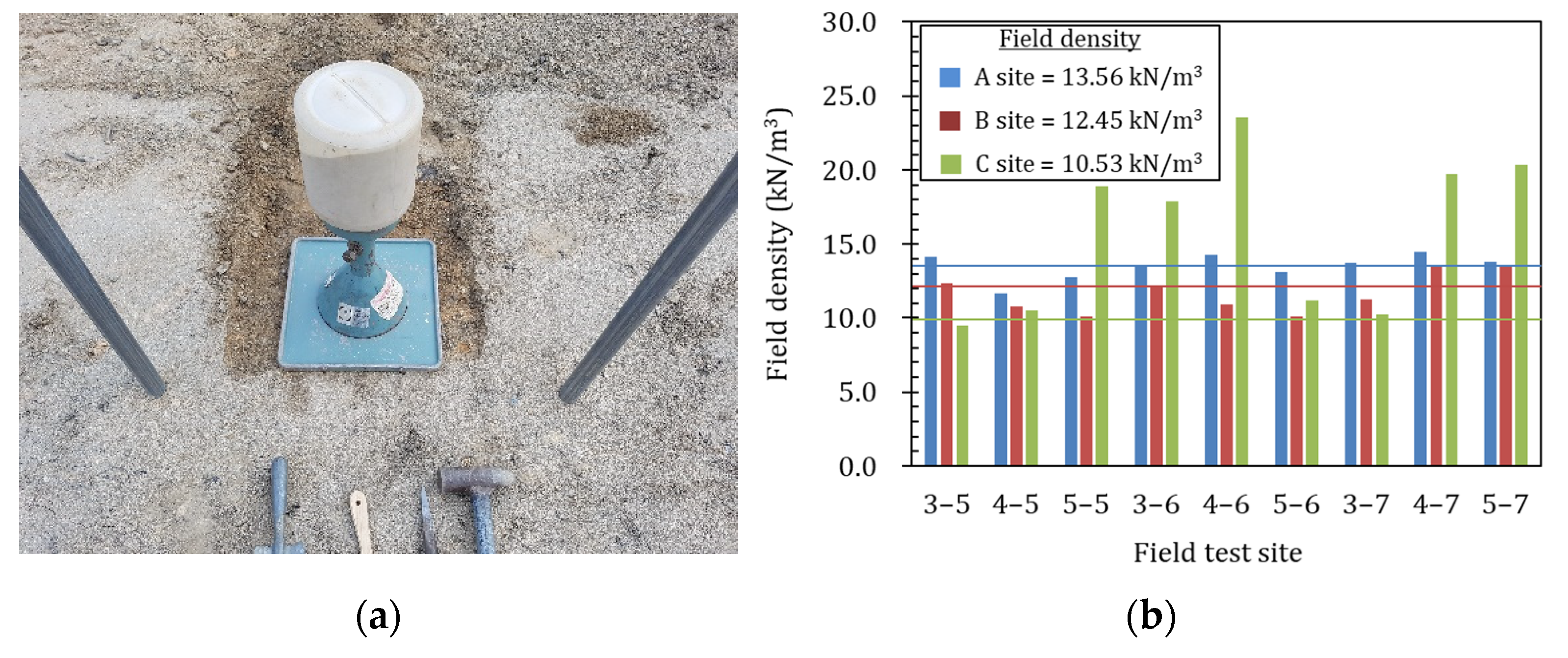
Figure 9.
Results of field uplift resistance on site A.
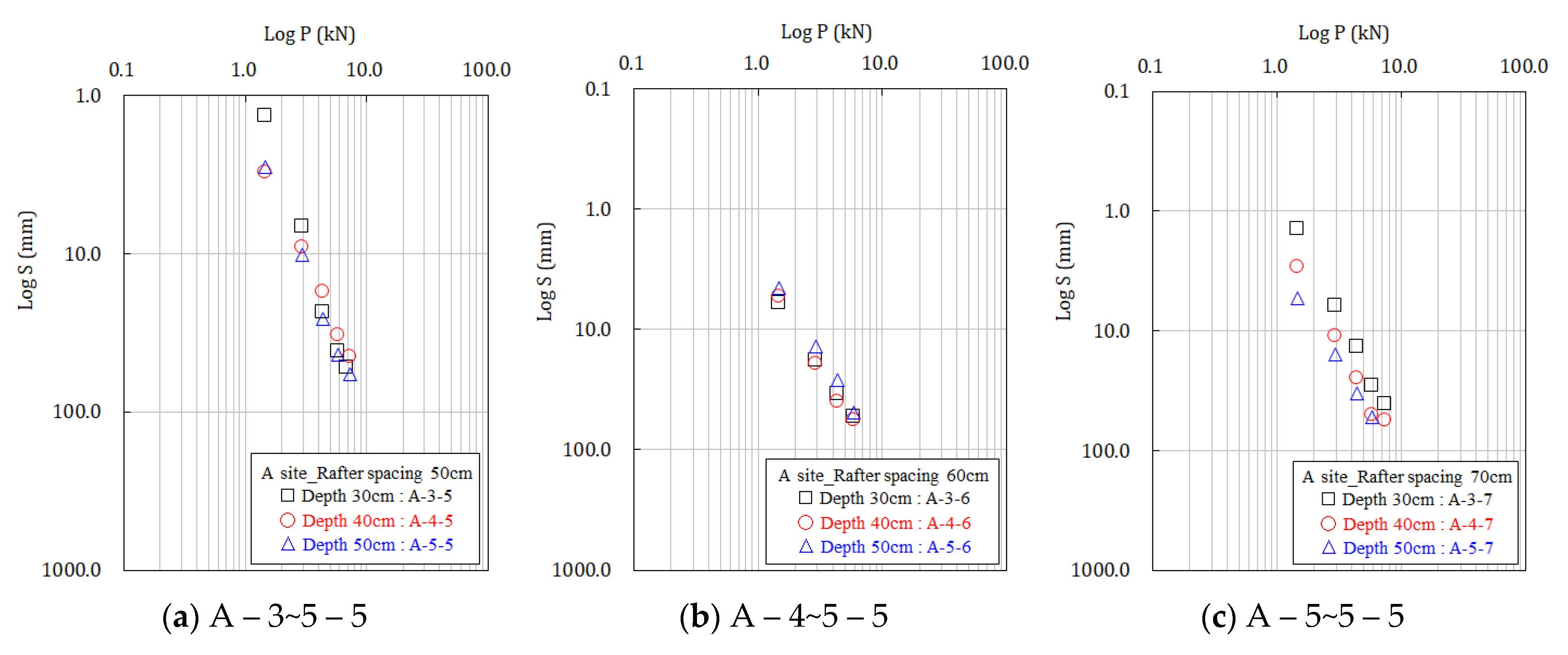
Figure 10.
Results of field uplift resistance on site B.
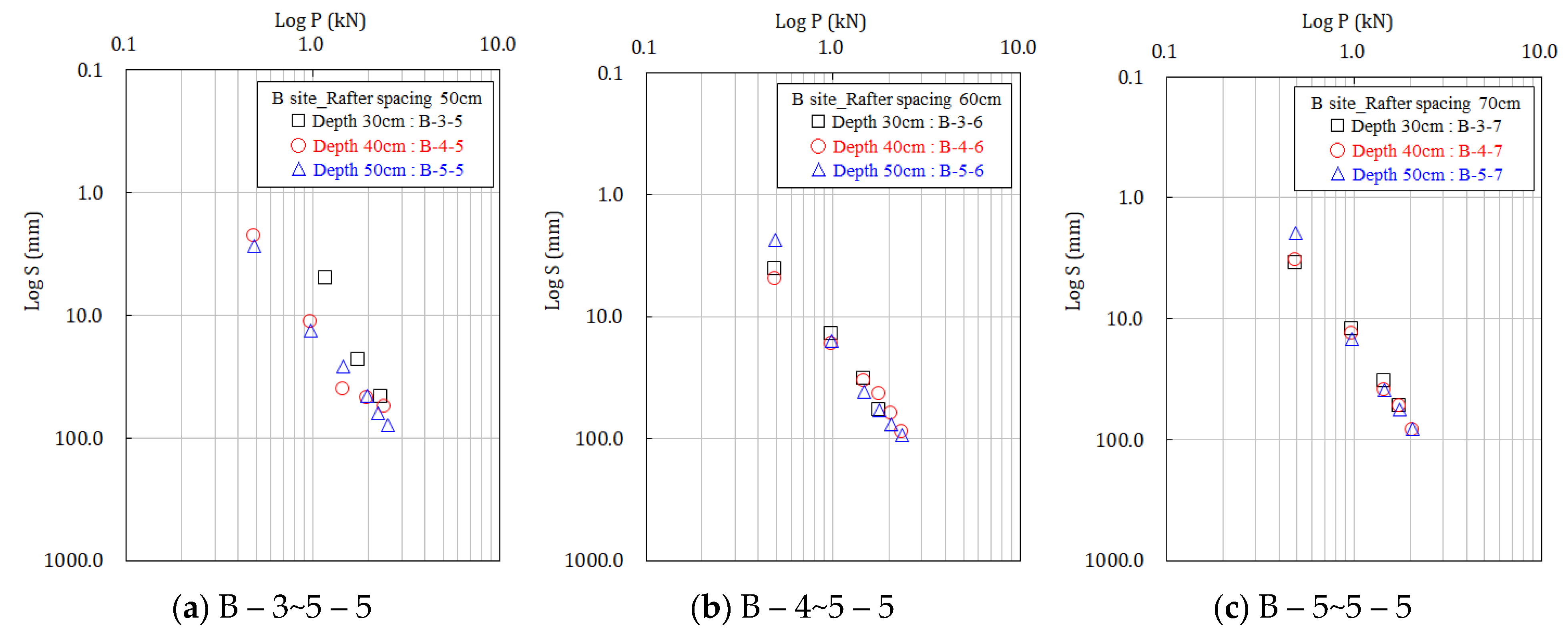
Figure 11.
Results of field uplift resistance on site C.
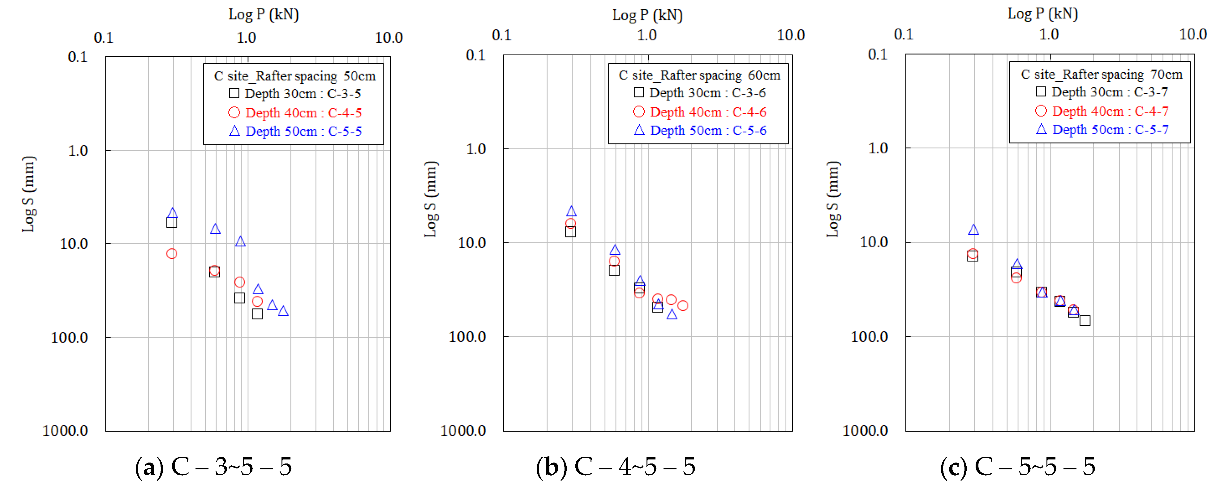
Figure 12.
Slipping of pipe connector: (a) uplift resistance test method of site A; (b) uplift resistance test method of site B; (c) uplift resistance test method of site C.
Figure 12.
Slipping of pipe connector: (a) uplift resistance test method of site A; (b) uplift resistance test method of site B; (c) uplift resistance test method of site C.

Figure 13.
Yield stress to rafter spacing on site A, site B, and site C: (a) yield stress to rafter spacing on site A; (b) yield stress to rafter spacing on site B; (c) yield stress to rafter spacing on site C.
Figure 13.
Yield stress to rafter spacing on site A, site B, and site C: (a) yield stress to rafter spacing on site A; (b) yield stress to rafter spacing on site B; (c) yield stress to rafter spacing on site C.
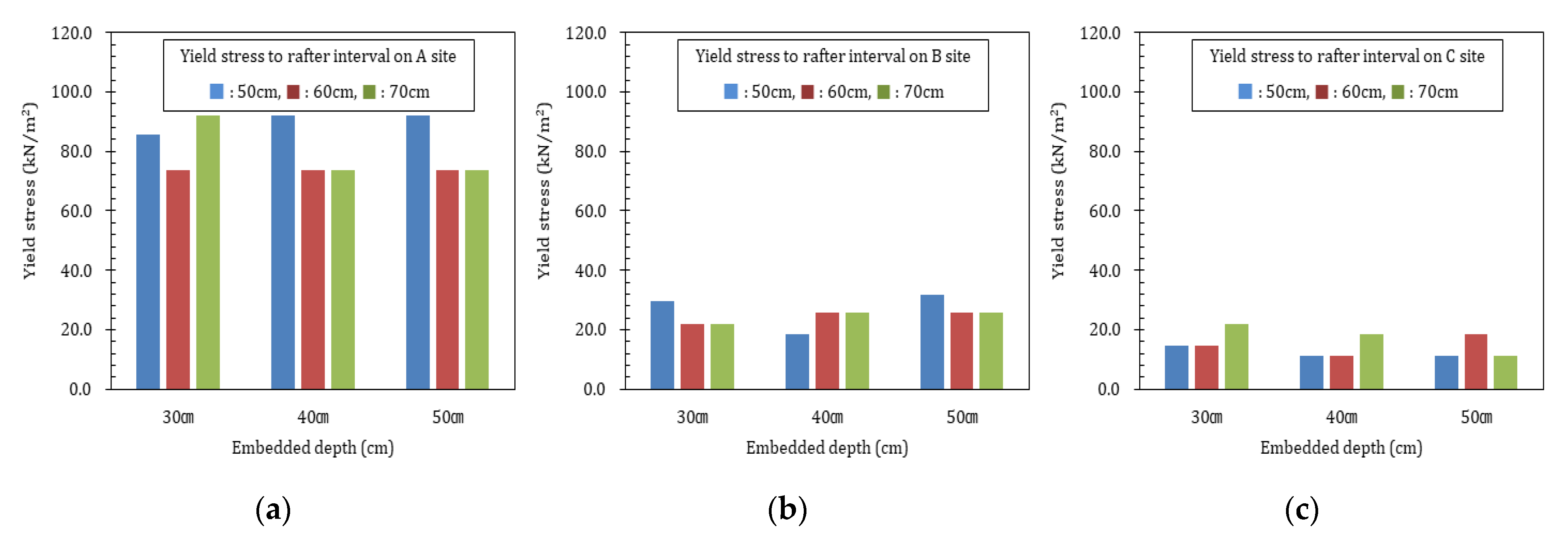
Figure 14.
Yield stress to embedded depth on site A, site B, and site C: (a) yield stress to embedded depth on site A; (b) yield stress to embedded depth on site B; (c) yield stress to embedded depth on site C.
Figure 14.
Yield stress to embedded depth on site A, site B, and site C: (a) yield stress to embedded depth on site A; (b) yield stress to embedded depth on site B; (c) yield stress to embedded depth on site C.
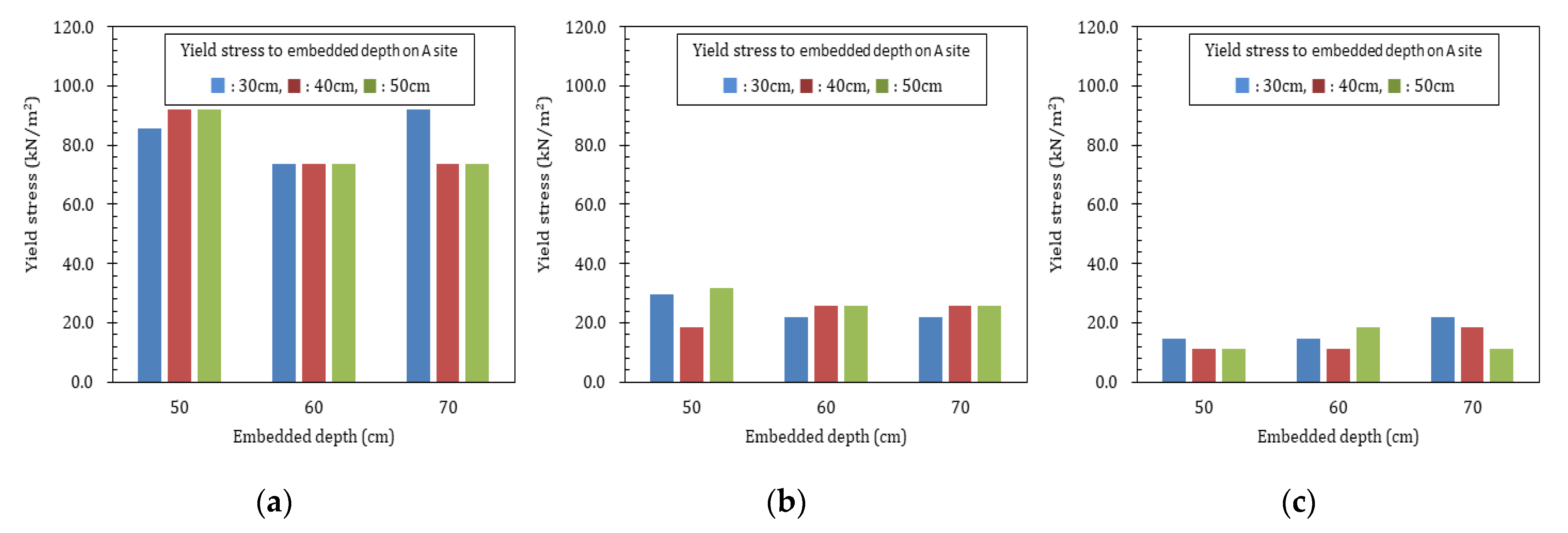
Figure 15.
Comparison of field dry unit weight and MIFAFF and RDA standard.
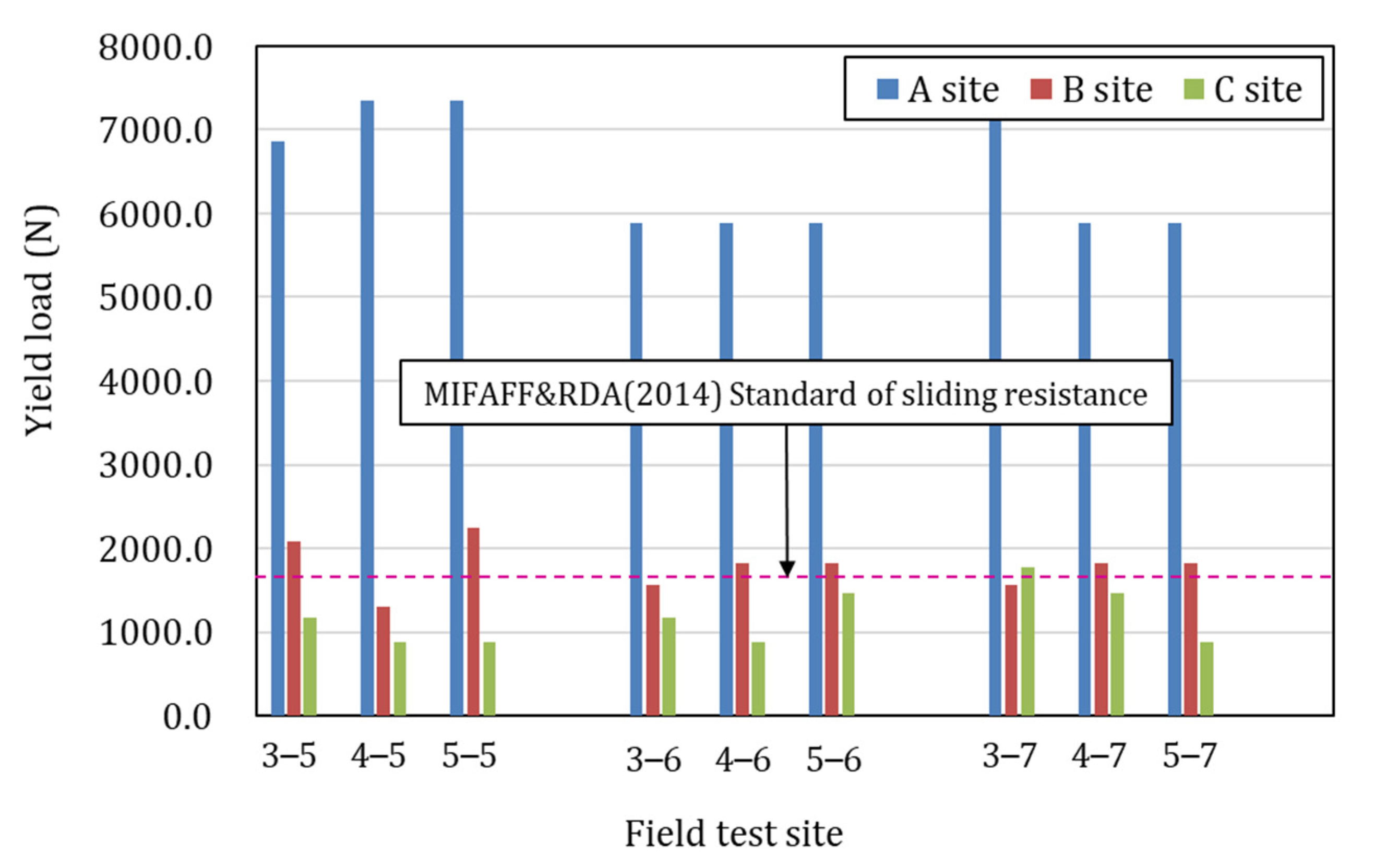
Figure 16.
Continuous pipe foundation for field test. (a) Steel wire, (b) steel plate [23].
Figure 16.
Continuous pipe foundation for field test. (a) Steel wire, (b) steel plate [23].


Table 1.
Mechanics and physical properties of soils on site A, site B, and site C.
| Site | Gs | LL (%) | PI | (kN/m3) | (kN/m3) | O.M.C | 4.76 mm (%) | 1.0 mm (%) | 0.2 mm (%) | 0.075 mm (%) | 2μ (%) | USCS |
|---|---|---|---|---|---|---|---|---|---|---|---|---|
| A | 2.62 | N.P | N.P | 13.56 | 19.17 | 11.4 | 83.4 | 77.2 | 49.4 | 35.5 | 7.5 | SM |
| B | 2.66 | 39.8 | 16.3 | 12.45 | 17.29 | 16.7 | 97.9 | 94.2 | 70.9 | 42.2 | 12.2 | SC |
| C | 2.61 | N.P | N.P | 10.53 | 15.84 | 18.4 | 100 | 99.8 | 99.0 | 65.1 | 5.5 | ML |
Gs: Specific gravity, LL: Liquid limit, PI: Plastic index, : Field dry density(field); : Dry unit weight of A compaction, O.M.C: Optimum water content; USCS: Unified soil classification system, N.P: Non plastic.
Table 2.
Foundation types of single-span greenhouse [3].
Table 2.
Foundation types of single-span greenhouse [3].
| Type | 07-Single -Span 1~4 | 10-Single -Span 1~5 | 10-Single -Span 6~9 | 10-Single -Span 10~13 | 07-Single -Span 18 | 12-Single -Span 1 |
|---|---|---|---|---|---|---|
| Rafter spacing (mm) | 500 | 400 | 500 | 400 | 500 | 500 |
| Embedded depth (mm) | 250 | 250 | 250 | 200 | 250 | 250 |
Table 3.
Test condition identification number.
| Site | Embedded Depth (mm) | Rafter Spacing (mm) | ||||
|---|---|---|---|---|---|---|
| 3 | 4 | 5 | 5 | 6 | 7 | |
| A, B, C | 300 | 400 | 500 | 500 | 600 | 700 |
Table 4.
Field dry unit weight on site A, site B, and site C.
| Site | Field Density (kN/m3) | ||||||||
|---|---|---|---|---|---|---|---|---|---|
| 3–5 | 4–5 | 5–5 | 3–6 | 4–6 | 5–6 | 3–7 | 4–7 | 5–7 | |
| A | 14.11 | 11.64 | 12.787 | 13.51 | 14.24 | 13.10 | 13.71 | 14.47 | 13.79 |
| B | 12.37 | 10.81 | 10.12 | 12.18 | 10.89 | 10.07 | 11.24 | 13.43 | 13.43 |
| C | 9.48 | 10.49 | 18.91 | 17.89 | 23.53 | 11.18 | 10.27 | 19.73 | 20.32 |
Table 5.
Ultimate and yield stresses of embedded depth and rafter spacing on site A, site B, and site C.
Table 5.
Ultimate and yield stresses of embedded depth and rafter spacing on site A, site B, and site C.
| Test Condition | Ultimate Stress (kN/m2) | Yield Stress (kN/m2) | |||||
|---|---|---|---|---|---|---|---|
| A | B | C | A | B | C | ||
| Spacing 50 cm | Depth 30 cm | 128.72 | 44.13 | 22.07 | 85.81 | 29.42 | 14.71 |
| Depth 40 cm | 137.91 | 27.59 | 16.55 | 91.94 | 18.39 | 11.03 | |
| Depth 50 cm | 137.91 | 58.50 | 16.55 | 91.94 | 31.87 | 11.03 | |
| Average | 134.85 | 43.41 | 18.391 | 89.90 | 26.560 | 12.26 | |
| Spacing 60 cm | Depth 30 cm | 110.33 | 70.40 | 22.07 | 73.55 | 22.07 | 14.71 |
| Depth 40 cm | 110.33 | 38.61 | 16.55 | 73.55 | 25.74 | 11.03 | |
| Depth 50 cm | 110.33 | 38.61 | 27.59 | 73.55 | 25.74 | 18.39 | |
| Average | 110.33 | 49.21 | 22.07 | 73.55 | 24.52 | 14.71 | |
| Spacing 70 cm | Depth 30 cm | 137.91 | 33.11 | 33.11 | 91.94 | 22.07 | 22.07 |
| Depth 40 cm | 110.33 | 38.61 | 27.59 | 73.55 | 25.74 | 18.39 | |
| Depth 50 cm | 110.33 | 38.61 | 16.55 | 73.55 | 25.74 | 11.03 | |
| Average | 119.52 | 36.78 | 25.75 | 79.68 | 24.52 | 17.16 | |
Table 6.
Yield load of slipping to pipe connector on site A, site B, and site C.
| Test Condition | Ultimate Uplift Load (N) | Yield Uplift Load (N) | |||||
|---|---|---|---|---|---|---|---|
| A | B | C | A | B | C | ||
| Interval | Depth 30 cm | 10,297.2 | 3530.4 | 1765.2 | 6864.8 | 2078.5 | 1176.8 |
| 50 cm | Depth 40 cm | 11,032.8 | 2206.8 | 1323.6 | 7355.2 | 1299.3 | 882.4 |
| Depth 50 cm | 11,032.8 | 4680.0 | 1323.6 | 7355.2 | 2251.6 | 882.4 | |
| Average | 10,787.6 | 3472.4 | 1470.8 | 7191.7 | 1876.5 | 980.5 | |
| Interval | Depth 30 cm | 8826.0 | 5632.0 | 1765.2 | 5884.0 | 1559.2 | 1176.8 |
| 60 cm | Depth 40 cm | 8826.0 | 3088.8 | 1323.6 | 5884.0 | 1818.5 | 882.4 |
| Depth 50 cm | 8826.0 | 3088.8 | 2206.8 | 5884.0 | 1818.5 | 1471.2 | |
| Average | 8826.0 | 3936.5 | 1765.2 | 5884.0 | 1732.1 | 1176.8 | |
| Interval | Depth 30 cm | 11,032.8 | 2648.4 | 2648.4 | 7355.2 | 1559.2 | 1765.6 |
| 70 cm | Depth 40 cm | 8826.0 | 3088.8 | 2206.8 | 5884.0 | 1818.5 | 1471.2 |
| Depth 50 cm | 8826.0 | 3088.8 | 1323.6 | 5884.0 | 1818.5 | 882.4 | |
| Average | 9561.6 | 2942.0 | 2059.6 | 6374.4 | 1732.1 | 1373.1 | |
| Standard deviation. P | 1027.4 | 999.5 | 465.5 | 684.9 | 267.9 | 310.3 | |
Table 7.
Ultimate uplift capacity according to pipe connector type [23].
Table 7.
Ultimate uplift capacity according to pipe connector type [23].
| No. | Ultimate Uplift Capacity (N) | |
|---|---|---|
| Steel Wire | Steel Plate | |
| 1 | 198.0 | 1441.0 |
| 2 | 175.0 | 1763.0 |
| Average | 186.0 | 1602.0 |
Publisher’s Note: MDPI stays neutral with regard to jurisdictional claims in published maps and institutional affiliations. |
© 2022 by the author. Licensee MDPI, Basel, Switzerland. This article is an open access article distributed under the terms and conditions of the Creative Commons Attribution (CC BY) license (https://creativecommons.org/licenses/by/4.0/).
Share and Cite
MDPI and ACS Style
Kim, M. Effects of Uplift Resistance on Continuous-Pipe-Foundation of Single-Span Plastic Greenhouse by Steel Plate Pipe Connector. Agriculture 2022, 12, 1998. https://doi.org/10.3390/agriculture12121998
AMA Style
Kim M. Effects of Uplift Resistance on Continuous-Pipe-Foundation of Single-Span Plastic Greenhouse by Steel Plate Pipe Connector. Agriculture. 2022; 12(12):1998. https://doi.org/10.3390/agriculture12121998
Chicago/Turabian StyleKim, Myeonghwan. 2022. "Effects of Uplift Resistance on Continuous-Pipe-Foundation of Single-Span Plastic Greenhouse by Steel Plate Pipe Connector" Agriculture 12, no. 12: 1998. https://doi.org/10.3390/agriculture12121998
Note that from the first issue of 2016, this journal uses article numbers instead of page numbers. See further details here.