2.3. Structural Design of the Axial Cylinder
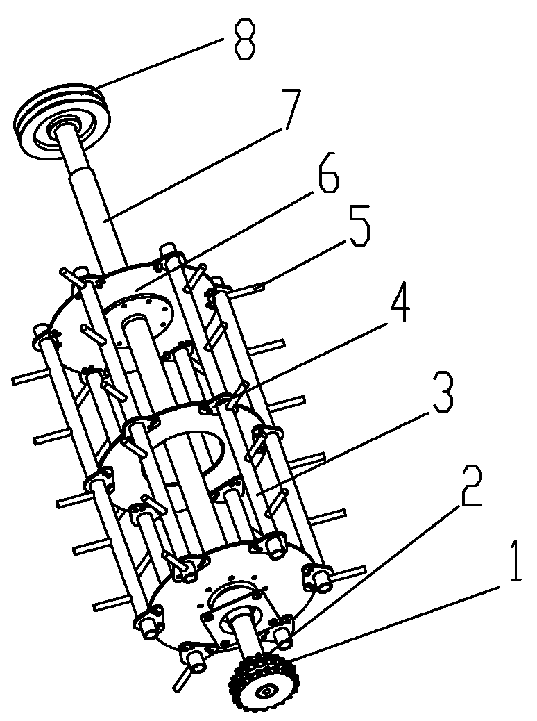
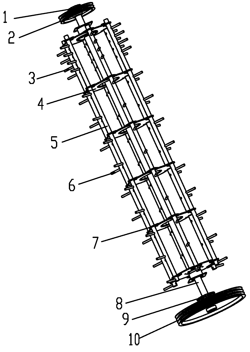
In order to facilitate trial production and reduce processing cost, the axial cylinder also adopts a spike tooth structure. As shown in
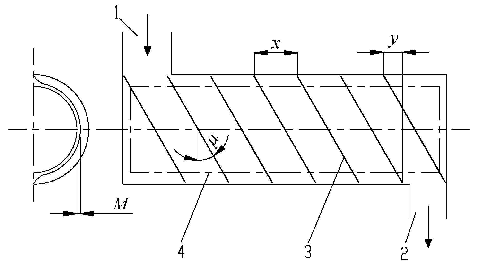
Figure 4, the designed axial cylinder is also composed of the toothed rod, toothed rod connector, spike tooth, toothed rod mounting disc, and transmission shaft. The power of the axial cylinder comes from the engine. During operation, the power is transmitted through the large pulley at one end, which drives the axial cylinder to rotate through the transmission shaft. At the same time, one power is transmitted to the tangential cylinder through the double row sprocket on the axial cylinder, the other is transmitted to the vine discharging assembly at the tail of the axial cylinder through the small pulley, and the third is transmitted to the screw auger through the sprocket of the axial cylinder.
2.3.1. Determination of the Length
The length of the axial cylinder determines the picking time and has an important influence on picking performance. Generally speaking, for a single peanut plant, the longer the picking time, the higher the picking rate. However, if the axial cylinder is too long this will also increase the picking power consumption and cleaning load (the broken number of vines increased). On the contrary, if the picking time is short, the non-picking rate will increase. During the picking operation, the peanut plant will make a spiral movement along the transmission shaft of the axial cylinder under the joint action of the spike teeth, the outer shell, and the concave screen. In general, the length of axial cylinder meets the following equation.
where
Lz is the length of the axial cylinder, mm;
Lzz is the length of the picking section of the axial cylinder, mm;
Lzp is the length of the vine discharging section of the axial cylinder, mm.
Among them, the length of the picking section of the axial cylinder meets the following equation [
15]:
where
Vz is the axial movement speed of the peanut plant during picking, m/s;
t is the picking time, s.
Some research results show that the optimum axial movement speed of peanut plant in axial cylinder picking operation is 483–600 m/s, and the picking time is 2–3 s [
15,
16]. Bringing these data into Equation (4), it can be obtained that the length of the picking section of the axial cylinder ranges from 966 to 1800 mm. Comprehensively considering the operating width of the peanut combine harvesters, the length of the tangential cylinder, and the characteristics of peanut plants after picking, it is finally determined that the length of the picking section is 1500 mm and the length of the vine discharging section is 400 mm, so, the length of the axial cylinder is 1900 mm.
2.3.2. Determination of the Number of Toothed Rods and Spike Tooth Parameters
In order to optimize the distribution density of the spike teeth of the picking cylinder, the number of the toothed rods is designed to be 6 and evenly distributed according to the circumference. Considering the long effective working length of the axial cylinder, in order to improve the picking efficiency and reduce the power consumption, the spike teeth on each toothed rod are designed to be evenly distributed and arranged according to the helix. Generally speaking, the number of helices is equal to the number of spike teeth passing through each tooth trace. The denser the spike teeth that are arranged spirally, the stronger the corresponding picking ability, but the too dense spike teeth will also cause peanut vine breakages and increase power consumption.
The number of the helixes is arranged according to the spike teeth of the threshing cylinder of the grain combine harvesters (mostly 2–5) [
12,
13,
14]. During the preliminary tests, the spike teeth on the axial cylinder are finally designed to be arranged according to three helixes. According to the size of the peanut plants, the distance between adjacent spike teeth on the same toothed rod is designed to be 180 mm, and the distance from side teeth to the end face of the toothed rod is 30 mm. The distance between spike teeth of the vine discharging is 60 mm, and the distance from side teeth to the end face of the toothed rod is designed to be 72 mm. At the same time, in order to facilitate processing, the sizes of spike teeth of the picking and vine discharging of the axial cylinder are designed to be the same as that of the tangential cylinder.
2.3.3. Determination of the Diameter and Speed
The diameter of the axial cylinder also has an important influence on picking performance. When other conditions are certain, the cylinder diameter is large, and the smoothness and efficiency of picking operation are also high. However, a diameter too large will increase the overall structural size and picking damage rate of the device. When the diameter of the cylinder is too small, it is easy to entangle and block the peanut vines. Similar to the tangential cylinder, the diameter of the axial cylinder meets the following equation:
where
Dz is the diameter of the axial cylinder, mm;
Dzg is the circumferential diameter of the toothed rods, which shall generally be greater than 300 mm [
13];
hz is the height of the spike teeth, mm.
According to the diameter of the existing peanut axial cylinder and considering the convenience of processing and installation, the diameter of the axial cylinder and the tangential cylinder are designed to be the same, that is, the diameter of the axial cylinder is 500 mm.
The speed of the axial cylinder is mainly determined by the linear speed at the end of the spike teeth when picking peanut pods and meets the following equation [
14].
where
nz is the speed of the axial cylinder, r/min;
vz is the linear speed at the end of the spike teeth, m/s.
According to the relevant research results [
6,
17,
18,
19], the axial cylinder has better picking performance when the linear speed at the end of spike teeth is 9–14 m/s. Bringing the data into Equation (6), it can be calculated that the speed range of the axial cylinder is 344–535 r/min. The preliminary pre-test research shows that when the speed of the axial cylinder is less than 400 r/min, the picking productivity is low, and the blockage problem will occur under the condition of large feeding amount. However, when the speed of the axial cylinder exceeds 475 r/min, the damage rate and entrainment loss rate of the peanut pods are more than 2%. Therefore, after comprehensive consideration, it is finally determined that the appropriate range of the axial cylinder speed is 400–475 r/min.
2.4. Structural Design of the Guide Plate
In order to ensure the picking performance and control the axial moving speed of the peanut plants during operation, seven spiral guide plates are designed on the inner surface of the axial cylinder outer shell. As shown in
Figure 5, in order to smoothly guide the peanut plants after tangential picking to the axial cylinder and avoid uneven feeding and blockage, the spacing between two adjacent guide plates is designed to be 260 mm and the front and rear overlap is about 110 mm. At the same time, in order to ensure that the peanut vines after picking can be smoothly exported to the discharging assembly and avoid blocking, the last guide plate is designed to extend into the discharging port.
The spiral rise angle and the clearance between the guide plate and the axial cylinder have a great influence on the picking performance. Generally, the spiral rise angle of the guide plate is 20–50°. If it is too large, the guide plate cannot realize the role of the axial push, and retention and accumulation of the peanut plants is easily caused. According to peanut plant characteristics and related studies [
6,
16], the spiral rise angle of the guide plate is designed to be 35°. When the clearance between the guide plate and the axial cylinder is too large, the axial fluidity of peanut plants becomes poor, which reduces the productivity and may even be blocked. If the clearance is too small, the damage of peanut pods will increase, and the power consumption is large. Especially when the peanut plant is wet, it is more likely to cause blockage. Referring to the size of peanut pods and related studies [
16], the clearance between the guide plate and the spike teeth of the axial cylinder is designed to be 15 mm and can be adjusted through the installation position of the axial cylinder shell to meet the needs of different varieties of peanut picking.
2.5. Structural Design of the Concave Screen
In addition to cooperating with the cylinder for picking, the concave screen should have strong separation capacity. At present, the commonly used concave screen is divided into grid format and punching according to its structure [
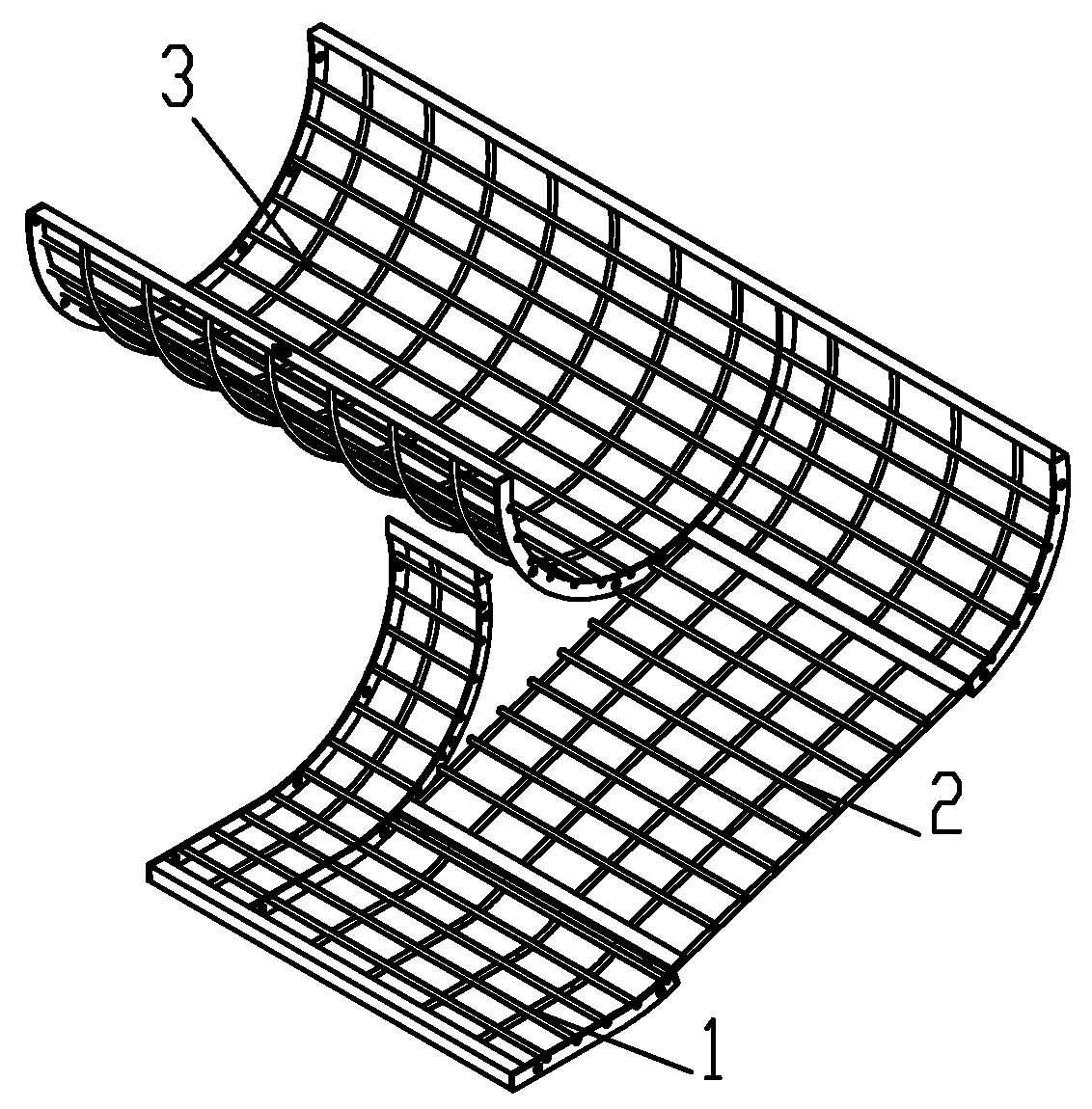
13]. The perforated screen is easy to process, but the screen porosity (the ratio of screen area to the total area of concave screen) is only 25–30%, and the separation rate is less than 50%. However, the porosity and separation rate of the grid format screen can reach 40–70% and 75–90%, respectively. Moreover, compared with the perforated screen, the grid format screen has stronger brushing off ability, so it is selected in this design.
As shown in
Figure 6, in order to facilitate the processing of the concave screen and the smooth and orderly migration of the peanut plants, the grid format screen adopts a combined structure. It mainly includes tangential flow, transition and axial flow sections. The separation screen hole is formed by crisscross screen strips.
Meanwhile, in order to ensure the picking performance of peanut plants in the tangential section and the smoothness of transportation to the axial section, the concave screen wrapping angle should not be too large [
13], which is taken as 95°. Due to the irregular shape of the peanut pods and poor fluidity, in order to improve the separation rate, the concave screen in the axial section adopts a larger wrapping angle, which is taken as 200°. At the same time, according to the size of the picking section of the tangential and axial cylinder, the width of the tangential section of the concave screen is designed to be 750 mm, the width of the transition section is 600 mm, and the width of the axial section is 1600 mm. The screen bar is made of round steel with a diameter of 10 mm. The transverse screen bar is located above the longitudinal screen bar, so as to improve the impact effect of the cylinder on the peanut plant and give full play to the picking and separating functions.
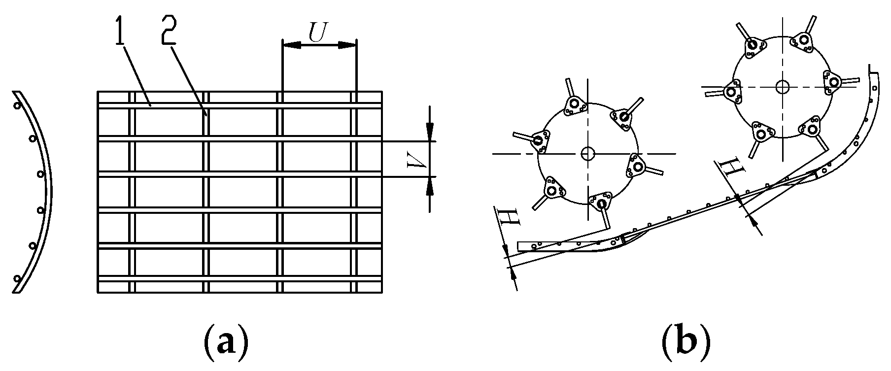
In order to ensure the separation capacity of the concave screen and considering the convenience of processing, the grid sizes of three sections of concave screen are designed to be the same. As shown in
Figure 7, the transverse dimension of concave screen grid is 120 mm and the longitudinal dimension is 90 mm.
The picking clearance is the gap between the concave screen and cylinder, which is the key parameter affecting the quality of the picking operation. Generally, if the picking clearance is small the peanut plant can be grasped well, which significantly improves the picking ability of the first half of the concave screen. However, a gap that is too small will increase the number of broken vines and easily cause damage to peanut pods. On the contrary, if the gap is too large, the ability of the cylinder to grasp the peanut plant and the separation ability of the front section of the concave screen are weakened, which seriously affects the picking quality. According to the size of the peanut pods and related studies [
7,
15], and considering meeting the needs of the peanut picking of different varieties and moisture content, as shown in
Figure 7b, the designed picking clearance range is 25–40 mm, which can be adjusted by the installation position of the concave screen.
2.6. Analysis of Feeding Amount of Peanut Plants
The feeding amount of the combine harvester should be equal to the product of the forward speed and the peanut plant weight per meter within the width of the harvesting operation. That is, the feeding amount is related to the forward speed and operating width of the combine harvester and the weight of the peanut plants per hectare. It meets the following equation [
13]:
where
Q is the feeding amount of the combine harvester, kg/s;
B is the operating width of the combine harvester, mm;
M is the peanut pod quality per hectare, kg;
β is the ratio of the peanut pod mass to total plant mass, %.
According to the previous tests and relevant literature [
5,
6,
20,
21], the forward speed of the peanut combine harvester is 0.8–1.5 m/s. According to field measurements and relevant literature [
15], the yield of the peanut pods in China is 3000–4500 kg per hectare, and the ratio of the peanut pod quality to total plant quality is about 45%. The operating width of the peanut combine harvester is 2500 mm. Substituting data into Equation (7), the feeding amount ranges from 1.33 to 3.75 kg/s. The previous single factor test results showed that when the feeding amount was less than 1.5 kg/s, the operation productivity was low and could not meet the production requirements of the peanut combine harvester. When the feeding amount exceeds 3.0 kg/s, the fluidity of the peanut plant is blocked and sometimes blocked during picking. Therefore, in order to ensure the normal operation of the picking device, the feeding amount of the peanut plant is finally determined as 1.5–3.0 kg/s.
Based on the above analysis and related studies [
5,
6,
7,
8,
15,
16,
17,
18,
19], the main factors affecting the operating performance of the picking device are the feeding amount of the peanut plant, the speed of the picking cylinder, and picking clearance. In order to further study the influence of these factors on the picking quality, and obtain the optimal operation parameters, it is necessary to carry out relevant performance tests.
2.7. Test Conditions and Instruments
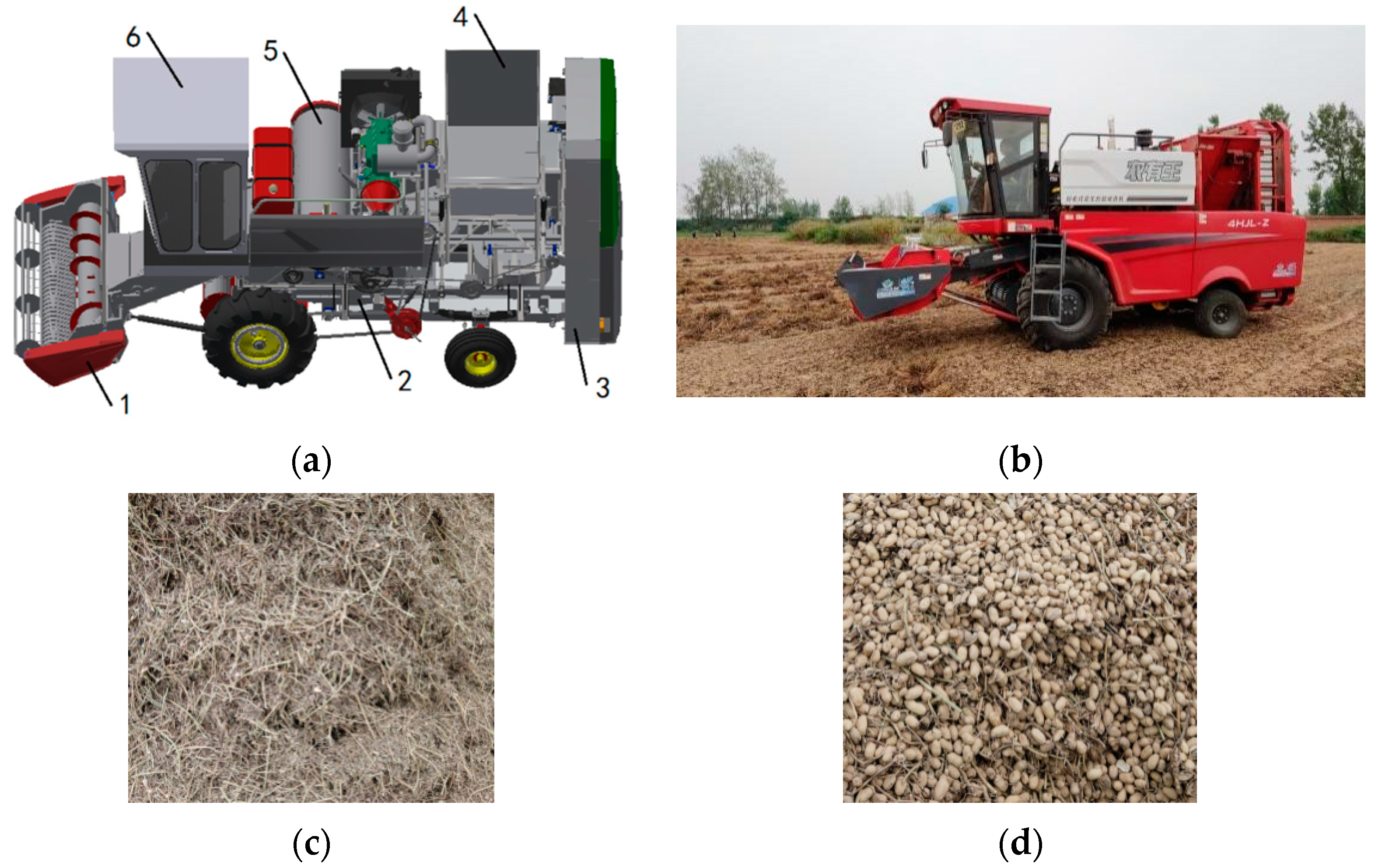
In September 2020, the test was carried out in Sanqiao Town, Henan Province, China. The planting scale of peanut in the test field is about 15 hectares. The terrain of the test field is flat, the soil type is sandy loam with some viscosity, and the crop planted in the previous season is wheat. The peanut variety is Wanhua 2. The planting mode is ridge cultivation, and the ridge distance is 85 cm. During the experiment, the peanut plants were dug up by a digging harvester and sun-dried for 5 days. At this time, the moisture content of the peanut vines was 15.60%, and the moisture content of the peanut pods was 17.82%, which meets the requirement that the moisture content is less than 20% during peanut combine harvesting [
22].
The designed and trial produced picking device was configured on the self-developed peanut combine harvesting prototype, and a movable peanut field harvest test bench was constructed to carry out experimental research. The field test process and test bench are shown in
Figure 8. The test bench was mainly composed of the pick-up device, picking device, cleaning device, collecting device, and cab. It can complete the operations of the picking, conveying, picking, cleaning, and collection at one time. Other main instruments include a tachometer (Model: FLUKE931, manufacturer: Fluke testing instruments (shanghai) Co., Ltd., Shanghai, China, measurement accuracy: +0.02%) and electronic balance (Model: HTP312, manufacturer: Shanghai Huachao Electric Appliance Technology Co., Ltd., Shanghai, China, measurement accuracy: 0.1 g).
2.8. Test Factors, Indexes, and Methods
According to the previous analysis, the orthogonal test with four factors and four levels was carried out. The feeding amount of the peanut plant, the picking clearance, the speed of the tangential cylinder, and the speed of the axial cylinder were taken as the test factors. The non-picking loss rate, entrainment loss rate, and damage rate of the peanut pods were the test indexes. The peanut picking performance was studied under different combinations of the feeding amount of 1.5–3.0 kg/s, the picking clearance of 25–40 mm, the speed of the tangential cylinder of 360–420 r/min, and the speed of the axial cylinder of 400–475 r/min. During the test, the forward speed of the movable test bench was changed to meet the requirements of different feeding amounts. The speed adjustment of the tangential cylinder and axial cylinder was realized by replacing the drive pulley or sprocket with different diameters. The adjustment of different picking clearance was realized through the installation position of the concave screen.
Based on the relevant contents of agricultural industry standard for the operating quality for peanut harvesters, NY/T 502—2016 [
22], it was defined that the non-picking loss rate is the percentage of the weight of non-picking after the picking device operation among the total weight of pods. The entrainment loss rate is the percentage of the weight of the removed pods discharged with the vines after the picking device operation among the total weight of pods. The damage rate is the percentage of the weight of the kernel and shell damaged pods after the picking device operation among the total weight of pods.
During the test, the length of each test measuring area was 10 m. Each group of tests was repeated 3 times, and the average value was taken as the final test result. After each test, intact pods and damaged pods were distinguished from the pods box of the movable test bench. Then the non-picking pods and pods taken away by the vines were determined. Finally, the non-picking loss rate, entrainment loss rate, and damage rate of peanut pods were calculated according to Equations (8)–(10).
where
yp is the non-picking loss rate, %;
yj is the entrainment loss rate, %;
ys is the damage rate, %;
mp is the weight of the non-picking pods, g;
mj is the weight of the pods taken away by the vines, g;
ms is the weight of the damaged pods, g;
m is the weight of the intact pods and damaged pods, g.
The arrangement of each factor is shown in
Table 1. An L
16(4
5) orthogonal table was established, in which
A,
B,
C, and
D are the coding values of each factor level.
Through the range analysis, analysis of variance, and fuzzy comprehensive evaluation [
23], the primary and secondary relationships of the effects of the feeding amount, picking clearance, cylinder speed on the non-picking loss rate, entrainment loss rate, and damage rate were explored, and the optimal parameter combination was determined.
However, through range analysis and analysis of variance, the influence order and optimal parameter combination of various factors on the test indexes were obtained, but the influence law and optimal combination were only for a single test index. In order to find an effective balance among the three test indexes, the orthogonal test results were analyzed by fuzzy comprehensive evaluation method, so as to obtain the optimal parameter combination meeting the three test indexes at the same time.
Firstly, the non-picking loss rate, the entrainment loss rate, and the damage rate were determined as the evaluation index set. The 16 groups of test result data of orthogonal test were the evaluation object set. Secondly, the membership function was established and the weight distribution set was determined. Finally, the fuzzy comprehensive evaluation value was calculated and analyzed [
23]. When the values of the non-picking loss rate, the entrainment loss rate, and the damage rate are smaller, the effect is better. Therefore, the membership function is established as follows.
Among them,
where
R is the membership function.
The primary goal of the picking device of the peanut combine harvester is to pick the peanut pods and avoid entrainment loss as much as possible. The non-picking loss and entrainment loss during picking are the direct sources of loss and should be strictly controlled. At the same time, according to the inspection and analysis after the test, most of the damage caused by picking operation is local damage of the shell, and only a few have pod fracture and kernel crushing. Therefore, through comprehensive consideration, it is determined that the non-picking loss rate and entrainment loss rate are the same proportions, and slightly higher than the damage rate. That is, the corresponding weight allocation set P = [0.4, 0.4, 0.2]. Then, the fuzzy comprehensive evaluation value is M = RP.


