Article

Stability Analysis of a Sprayer UAV with a Liquid Tank with Different Outer Shapes and Inner Structures

1
School of Agricultural Engineering, Jiangsu University, Zhenjiang 212013, China
2
Key Laboratory of Modern Agricultural Equipment and Technology, Ministry of Education, Jiangsu University, Zhenjiang 212013, China
*
Author to whom correspondence should be addressed.
Agriculture 2022, 12(3), 379; https://doi.org/10.3390/agriculture12030379
Submission received: 16 January 2022 / Revised: 26 February 2022 / Accepted: 4 March 2022 / Published: 8 March 2022
(This article belongs to the Special Issue Application of Decision Support Systems in Agriculture)

Abstract

:
The performance of sprayer UAVs largely depends on accurate trajectory control while spraying. A large amount of a liquid payload may create a sloshing effect inside the liquid tank, which may occur largely during hazardous phenomena, such as wind gusts and obstacle avoidance. This all-way sloshing force inside the tank may disturb the UAV’s trajectory by, for example, a displacement from the planned path or collision with an obstacle. A large number of existing sprayer UAVs already carry various-shaped tanks. A UAV’s liquid-sloshing problem must be reduced for existing and future plant protection. Applying suitable methods can achieve these goals and provide better performance. Moreover, various tank models have different structures and capabilities, which must be fixed using a flexible solution. This article proposes a simple baffle solution for all forms of pesticide tanks and compares baffle systems’ impacts using primary shaped tanks. Indoor lab experiments showed the extreme impacts inside the tanks. Outdoor UAV mission experiments provided the practical effectiveness of the tank structures, and primary shaped tank comparison results provided guidance for future UAV pesticide-tank manufacturing. A new baffle ball design is presented for a universal solution. A one-axis linear slider was used for optical observations, an open-source flight controller was used for on-field compliance, and plenty of tests were done to prove the concept and show the efficiency. The flat hexagonal tank and baffle ball system showed better results in both indoor and outdoor experiments.

1. Introduction

Decreasing the number of humans involved in agricultural fieldwork and increasing food consumption makes farmers more dependent on unmanned agricultural vehicles. Following that, the usage rate of unmanned aerial vehicles (UAV) has increased alongside that of unmanned ground vehicles [1]. This category of IoT devices is now a significant part of precision agriculture, and one of the largest sectors is plant protection via UAV spraying technology [2]. Research studies are actively conducted on Unmanned Aerial Vehicle (UAV) developments and adaptions [1,2] for agricultural practices with higher precision, and they are mainly used for field mapping [3,4], plant stress detection [5,6], biomass estimations [7,8], weed management [9,10], inventory counting [11], chemical spraying [12,13], and auxiliary pollination [14], etc. The most widely used application is spraying pesticides by using UAVs for plant protection in all of these applications. Spraying pesticides on crops is a compulsory operation that is applied multiple times during a crop’s lifetime. As a part of high-tech precision agriculture, the development of intelligent, reliable agricultural pesticide-sprayer UAVs is growing very quickly. Technologically advanced countries, such as China, the USA, Japan, Korea, and European countries, are increasing the involvedness of unmanned aerial vehicles in the agricultural sector [3,4,5,6]. Especially for mitigating the health risks of human-operated pesticide sprayers and faster operation, using UAVs for spraying is the best way to save money and time and to protect human health [7]. These kinds of UAVs carry a large-sized liquid tank, which contains a select liquid pesticide solution. Moreover, these tanks are different in shape and size depending on the different models and capacities of the UAVs. These tanks each carry a decreasing liquid load, and the payload inside may create different slosh effects at different times during a spray operation. This unpredictable phenomenon may cause an unstable maneuver of the UAV and may create a flying disturbance.

1.1. Motivation

Maintaining an effective droplet deposition, safety rules, and flight stability during a sprayer UAV’s operation is a key part of precision agriculture [15,16]. In farmland, uncontrollable weather conditions, such as sudden wind direction changes, and complicated obstacles, such as plant protection nets, power lines, towers, lighting structures, and buildings, are the most common difficulties for sprayer UAVs [17]. Facing and tackling those difficulties, such as sudden flight path changes, is a common phenomenon for this kind of liquid-carrying UAV particularly during the flight operation of an agricultural UAV in the field. Sudden trajectory changes and stabilizing the operation of the sprayer UAV becomes more difficult because of the attached tank’s liquid sloshing. This liquid sloshing produces a continuous shock effect for the UAV [18]. In Figure 1, the disturbance of the slosh effect is shown. The UAV faced an obstacle and automatically tried to avoid it, and sloshing made the flight unstable. The sequence is from (a) to (f) in Figure 1. The automatic avoidance performance was performed using the K++ flight controller and an agricultural sprayer UAV [19].
Currently, there is a large number of studies on droplet depositions [13], control effects after spraying [14], spray-system designs [15], and remote-sensing designs [16,17], etc. However, very few studies have been done about slosh control inside the tank of a sprayer UAV. To fly autonomously and spray precisely, the vehicle must be stable on the flight and ensure all kinds of safety, whereby liquid sloshing during the operation is a hazardous issue.
An effective tank structure and the inner baffle system can reduce the sloshing effect and increase vehicle safety. We have stated the main objectives for this study below:
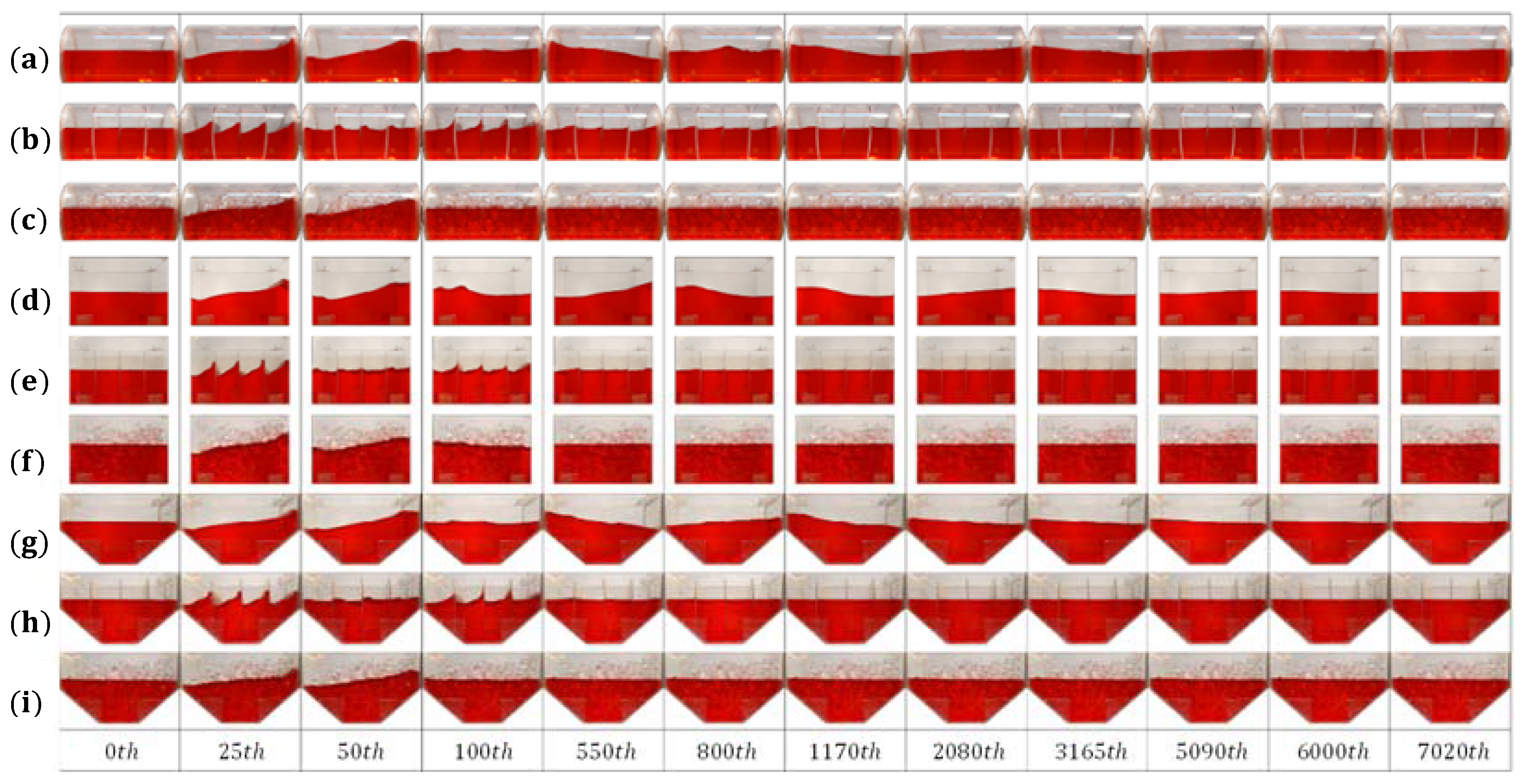
  • An experimental study of the slosh effect using different shaped tanks, inner baffle systems, and different liquid levels using a linear-guided motion machine and a high-speed camera.
  • An aircraft principal axes analysis of a model-sized sprayer rotorcraft UAV carrying a select tank setup.
  • A time and height evaluation of water sloshing for a better effective tanker system.
  • A flight inconsistency evaluation to prove the system’s effectiveness for rotorcraft UAVs.

1.2. Contributions

The contributions of this study are given below:
  • Three primary shaped-tank effectiveness tests and a result comparison.
  • Multiple water-level experiments and analyses with a high-speed camera.
  • Two inner baffle system tests and effectiveness comparisons.
  • A new baffle ball introduced for universal use in commercial UAV tanks.
  • An aircraft principal axes evaluation for an efficiency check.

1.3. Implications

This study shows the pathway of a better liquid-slosh management system and solves the sprayer-UAV sloshing problem during critical flight maneuvers, such as obstacle avoidance and wind turbulence. Therefore, a new baffle ball has been shown to solve the sloshing effect of the previous models of the sprayer UAV’s tank and future general models. It has also demonstrated the effectiveness of using baffle walls inside the tank by doing multiple water level tests with a one-axis linear-guided motion system. This solution will add value to precision agriculture as well as agricultural automation.
To check the method’s effectiveness, multiple experiments have been done in two phases. In phase one, using a linear-motion-guided machine, high-speed camera, and liquid-poured tank, and in phase two, using a rotorcraft UAV and select liquid-poured tank with different liquid levels, these parameters have been assessed: (a) empty tank tests (b) including baffle wall tests and (c) including baffle ball tests.
This study considers both the previous tank-model and future tank-model design concepts. Multiple flight tests have been shown using different tank models and baffle systems to prove the study’s purpose, compare solutions, and find a better solution.

1.4. Organization of the Article

This article is organized following this structure: Segment 1 presents the originality, motivation, quick results, contributions, and implications of the study. Segment 2 presents the background of liquid-sloshing and reduction-related research and methods. Segment 3 presents the system’s architecture, including tanks, baffle-wall and baffle-ball designs, linear-guided motion frames, quadrotor frames, and flight controllers. Segment 4 presents the experimental methods, including the indoor-tank and outdoor-UAV flight-mission experiments. Segment 5 shows the comparison and discussion of the results, including a slosh-height and impact-duration comparison and UAV flight-record comparison during the mission. Segment 6 concludes the research and suggests future work and possibilities, and segment 7 shows references.

2. Background and Related Work

Studies about liquid sloshing have been done mainly by doing theoretical analyses [20,21], experimental analyses [22,23], and computer simulation analyses [24,25], etc. Moreover, much research has focused on reducing sloshing in large liquid-gas tanker vehicles, oil tanker vehicles, and spacecraft [26,27]. Several studies have been done on anti-sloshing technology by many researchers. For example, Xue et al. [28] used four types of vertical baffles to reduce the slosh effect and monitor pressure distributions on the baffles for the rectangular-shaped tank. They used a single vertical baffle wall at the middle of the tank to monitor the impact on the wall. Arif et al. [29] used a floating baffle-wall setup to reduce maintenance costs and made the baffle grid wall a floating object for the LNG tanks. A porous baffle-wall system has been used in a rolling rectangular tank to analyze the potentiality of the cavity on the wall by George and Cho [30]. Another anti-sloshing technique using floating foam in a rectangular tank and studying the hydrodynamics has been done by Zhang et al. [31]. Qin et al. [32] used a single-level vertical baffle wall to compare it with a horizontal baffle wall considering hydroelectricity. Studies on cylindrical or elliptical tanks are mainly done for compressed-gas and oil tankers. For example, Wang et al. [33] proposed a method based on finite-element technology and used a T-shaped baffle on liquid sloshing in horizontal elliptical tanks. Hasheminejad and Mohammadi [34] installed a pair of internal rigid horizontal side baffles of arbitrary extension at the free-liquid surface and a bottom-mounted rigid vertical baffle of random attachment along the tank’s vertical axis of symmetry in a horizontal circular-cylindrical tank. The characteristics and impacts of ring baffles inside horizontal circular-cylindrical tanks were investigated by Liu et al. [35]. For a vertical circular-cylindrical tank, Maleki and Ziyaeifar [36] used horizontal circular-ring and vertical blade baffles targeting space-vehicle tanks. Other studies on different baffle systems for different shaped tanks are done to reduce sloshing problems [37,38,39,40,41].

3. System Architecture

For the phase one experiment, we created a linear-guided tank slider structure for smooth motion acceleration and the quick stop. We have created this simple system that has been built with some local hardware and a microcontroller to control the exact movement. In total, the whole system contains four major essential parts: (a) slider hardware, (b) micromotion controller, (c) a tank body, and (d) the inner baffle systems of the tank. Then for the phase two experiment, we created a primary physical model of an agricultural quadrotor sprayer UAV’s structure and different tank structures with an open-source flight controller. This system also contains four major essential parts: (a) the hardware of the quadcopter, (b) the flight controller, (c) the tank body, and (d) the inner baffle system of the tank. The overall control architecture is shown in Figure 2, and the detailed model is shown in the following subsections.

3.1. Tank, Baffle Wall, and Baffle Ball Designs

There are so many types of tanks for sprayer UAVs on the market, whereby different sprayer-UAV manufacturing companies make different shaped models [42]. Thus, we used fundamental shapes to confirm the average formations of tanks and analyze the baffle system’s effectiveness in the base-shaped tanks. In Figure 3, we illustrate the tanks, where the rectangular tank’s volume is 12 , 000   cm 3 , the flat hexagonal tank’s volume is 11 , 500   cm 3 , and the horizontal cylindrical tank’s volume is 11 , 310   cm 3 . We have made similar-volume tanks for result comparisons and accuracy. Then we have made the baffle walls with the cavities, where the cavity sizes for all three types of the tank are similar, and all cavities are placed at the bottoms of the walls as shown in Figure 4. The rectangular and flat hexagonal tanks’ walls contain two holes, where a = b = 2.5   cm and c = 5   cm , and the cylindrical tank’s wall contains one hole, where d = 5   cm and e = 2.5   cm .
At last, we designed and made a baffle ball that was usable for any tank shape. This design was made out of 0.2   mm -thin PVC sheets. As shown in Figure 5, we cut down the sheets and formed the spheres step by step. The red, green, and blue colored lines are equal in length and width, which are 160   cm and 1   cm , respectively. The mentioned gap distances are x = 75   cm , y = 30   cm , and z = 35   cm . These baffle balls are designed by considering complex tank manufacturing with inner structures and the existing UAV tanks. However, these balls are efficiently designed at the lab for experiments and for mass-scale manufacturing; they can be made for any kind, shape, and size of existing UAV tank.

3.2. Guided Linear-Motion Frame

To simulate the translation motion, we developed an experimental device presented in Figure 6. A simple one-axis sliding device has been made using a stepper motor and timing belt. The stepper motor has been used to increase and decrease the motion of the tank’s platform using a microcontroller. The experiment system hardware was developed with a 5M30 gear, a pulley (a), 5   M timing belt (b), two 12   mm diameter and 2   m -long SS rods (c), a tank platform (d), four SBR12 linear bearings (e), four SK12 rod holders (f), a NEMA-34 stepper motor (g), and a DM860T motor controller (h), which are presented in Figure 6. An Arduino microcontroller was used to program the motor controller to accelerate and stop the platform.

3.3. Quadrotor Frame and Flight Controller

We set up an industrial-grade quadrotor frame with an industrial-grade BLDC motor to acquire a realistic experiment result. In Figure 7a, we have shown the 3D model of the quadrotor frame and rotor setup, with (i) electronics and flight-controller box and upper part of the frame (ii) 45   cm long with 4 cm diameter hollow arm, (iii) 72 cm propeller with M A X 15   kg thrust-capable rotor set, (iv) 533   WH and 44   V power source, (v) landing gear, (vi) aluminum-casted 17 × 17   cm main-frame holder, (vii) Pixhawk flight controller, and (viii) uLanding C1 microwave height sensor. All equipment of the quadrotor is made of locally sourced materials and equipment. The primary frame holder and electronics equipment holder are made from cast aluminum, the rotor arm and landing-gear pipes are made of composite carbon-fiber material, t-sockets are made of PVC plastic, the landing gear pads are made of rigid foam material, and the rotor set models are XRotor Pro X8s from company Hobbywing [43]. Each rotor can create 15.3   kg /axis thrust, and the propeller model is L3090.
In the other parts of Figure 7, we have shown the open-source flight controller and its accessories. This experiment is based on attitude monitoring during the slosh effect inside the tank of the UAV. Most commercial UAV companies don’t provide access to detailed flight data from their software. Thus, we set up a flight controller with flight firmware to get all the relational data of the test. We used open-source Pixhawk 4 FMUv5 flight-controller hardware [44] and Copter 4.1.0 [45] firmware for this experiment.

4. Experiment Methods

To evaluate the effects of sloshing inside a tank, multiple evaluation methods have been implemented by researchers, such as weighted methods [46,47,48], artificial neural network method [49], and comprehensive indexing method [50]. However, to analyze the effect of sloshing of liquid on sprayer UAV, implementing the methods in indoor lab experiments is insufficient. Therefore, we conducted this paper’s comprehensive evaluation of indoor tank sloshing and outdoor flight tests. For both phases of experiment, first, we used three basic-shaped tanks containing similar liquid capacities. Then, we created a basic 3-level baffle-wall system for these tanks to monitor the reduction of the sloshing effect. Lastly, we made simple, lightweight baffle balls for all tanks to show a final sloshing reduction. We used freshwater as the experimental liquid for all experiments. All kinds of liquids carried by sprayer UAVs are mixtures of freshwater and select chemicals or pesticides, which become denser after mixing. Thus, we selected a less dense liquid for the experiment. An average-sized tank (10 L) is used, whereas a smaller tank generally faces a smaller slosh impact and a larger tank faces a larger impact. Smaller-size tank faces have smaller slosh impacts and larger-sized tank faces have larger impacts. Appropriate indicator selection, height determination, formula establishment, and calculation are the main operation steps. Then, for comparison, index syntheses were performed according to average time, height, and inconsistency indexes.

4.1. Indoor Tank Experiment

For the phase one experiment, we first assembled the linear-motion system hardware capable of accelerating motion from zero to targeted speed and stopping at the highest speed. Then, we attached the tank to the motion bed of the system and fixed the highest speed and travel length using a microcontroller. Then, we set up a high-speed camera to record the liquid’s motion for frame-by-frame analysis. In Figure 8a, we have shown the phase one experiment method. The program was set to start the movement of the tank platform with velocity of 0   ms 1 from starting point l . Then, it accelerated the tank velocity up to 0.25   ms 1 and then hard stopped at point m , intended to create a sloshing effect at that moment. We started the acceleration of the tank platform from zero to keep the liquid’s surface-level flat to monitor the precise impact of the surface level via a high-speed camera. The impact tolerance of our system without liquid splashing out and stepper speed was 0. 4   ms 1 . The travel distance of the platform was 1.5   m . Now, to do the sloshing experiment and directly measure the variations in the water’s free surface by force, we used a camera instead of the ultrasonic sensor. This was because the ultrasonic sensor has so many observational errors, low response time, and low resolution [51]. Thus, for the first phase of result extraction, we collected the direct measurement of the free surface of the liquid via captured image. We used fresh water with a red color, full transparent tanks, and enough lighting to obtain accurate liquid surface displacement. The high-speed camera was capable of capturing video with 240 frames per second and 1080p resolution. Using software Adobe Premiere Pro at first, we collected the slosh impact time duration using the motion-detection feature. The fluctuation recovery time refers to the time needed for the liquid to move from the fluctuation state to the stationary state. Here, the fluctuation recovery time is calculated using Equation (1), where t is the fluctuation recovery time, n is the number of photo frames taken by the high-speed camera, and f is the number of frames per second (fps).
t = n f
In Figure 9, all nine types of tanks’ set observation frames have been shown, where we have demonstrated the impact of time-snaps on sloshing in the open and baffle conditions. The slosh-effect reduces significantly using a baffle system, creating a short impact time. We used short interval snaps at first and long interval snaps last. Using only short interval snaps makes a huge snap series, and using very long interval snaps misses the short-impact visibility. That’s why we used gradual intervals from short to long. Then we extracted every frame, analyzed the sloshing time, and converted the first sloshing-impact images using software Adobe Photoshop into threshold image and wave line. After that, we traced the height of the normal liquid surface and set the surface line as y-axis at zero level. Then, we extracted the slosh surface line, converted it into a graph curve, and collected the graph data using software GetData Graph Digitizer. Finally, from the graph data, we measured the surface variations of the liquid and collected the peak heights of the liquid’s surface using software OriginPro. In Figure 9, we have shown the image-extraction, comparison, and data-extraction processes. In Figure 10c, H T is the height of the tank and H L is the height of the liquid. Figure 10d shows multiple surface and peak data points. The index calculation formula of slosh height comparison is shown in Equation (2), where, H y is the peak height of an individual type tank, P l is the peak height in different liquid-level experiments, and i is the number of experiments.
t = n f

4.2. Outdoor UAV Flight Experiment

For the phase two experiment, we assembled a quadcopter capable of carrying a maximum 12.1   kg payload, and then, we set up the hardware with an open-source flight controller to conduct the experiment flight and obtain all kinds of flight data. After that, we attached the payload under the quadrotor frame. Then, we calibrated and fixed the PID values for the operations. As we configured it before, the empty rectangular, flat hexagonal, and cylindrical tanks’ weights were 1.125   kg , 1.100   kg , and 1.225   kg , respectively, and the baffle walls’ weights were 0.360   kg , 0.180   kg , and 0.630   kg , respectively. Every test carried 7   L of water inside the tank, intended to create higher pressure for the UAV. Figure 8b shows the phase two experiment method, where we attached the tanks to the UAV and did a flight test. We have made a mission plan for the UAV, and the UAV completed a planned mission carrying different tanks and baffle systems. The mission’s take-off and landing coordinates were latitude 32.2026195 °   N   and longitude 119.503185 °   E . We chose a calm day for the experiment, where the wind speed was 4   kmh 1 in a westerly direction and the experiment date was 21 August 2021 after 5:00 p.m. GMT + 8 h [52]. Furthermore, we choose a building’s covered area to obtain the help of natural wind-speed reduction, as shown in Figure 11a. We planned the mission using software Mission Planner Ground Control Station. As we have shown in Figure 8, in the mission, we set three initial waypoints for flight path, and after taking off from w p 1 (waypoint 1), the UAV will hover at altitude of 4   m . Then, it started going forward with flying speed of 3   ms 1 , and after flying at 25 m, it stopped and hovered at w p 2 . It delayed 5 s at that point and started moving to the right towards w p 3 . After flying 18 m, it stopped and hovered again for 5 s at w p 3 . Then, it started flying left towards w p 2 and stopped again for 5 s. Lastly, it came back to w p 1 , waited for 5 s and landed. This flying mission was set to check the flight turbulence of the UAV with liquid tanks and a baffle system. The forwards–backwards flying and stop was for pitch and right–left flying, and it stopped for roll inconsistency check.
During a mission, a UAV changes the pitch and roll angle to move on the x-axis and y-axis, which also changes the angle of the tank. The continuously changing angle and movement of the UAV changes the center of the gravity of the liquid inside the tank, which creates a liquid-sloshing effect inside the tank. Ref. [53] has shown a model of centers of gravity changing while agricultural vehicles change their angles. The same gravitational force-changing phenomena happen with aerial vehicles during their operation. In Figure 12, we have shown the center of gravity changing in the liquid tank. While the pitch or roll angles change and create horizontal accelerations and decelerations, the liquid slosh creates extra force for the UAV. This additional force can affect the changing angle of the UAV. For a mission or automatic control, the flight controller obtains the directions of the mission plan from ground control and gives roll- or pitch-changing angle commands to create acceleration or deceleration. The angle-changing commands also vary depending on the vehicle’s physical and aerodynamical condition. Following that, the UAV gets a desired pitch-and-roll command from the flight controller, but it achieves different pitch and roll angles, which are always recorded by the flight controller. Thus, in an automatic flight mission, the gap between desired roll or pitch angle and the achieved roll or pitch angle should be closer. The more a gap between these two angles, the more a disturbance by the liquid-sloshing effect.
We extracted all flights’ desired pitches and roll angles and achieved roll and pitch angles from the flight-log data using software Mission Planner. Then we separated all the data and calculated the average difference between desired and achieved grades. We recorded the data using all types of tanks and baffle systems individually and without tanks as well so that we could compare the stable flight data. The indexing of flight data of the UAV is shown in Equation (3), where I P e is the average pitch inconstancy of the pitch angle during the mission, P d is the vehicle-desired pitch angle, P a is the achieved pitch angle, and k is the total number of inconsistency records of every 1 / 10 -s value during the entire mission. Similarly, R d is the vehicle-desired roll angle, R a is the achieved roll angle, and I R e is the average roll inconsistency.
I P e = | P d P a | 0     + | P d P a | t k
I R e = | R d R a | 0     + | R d R a | t k  

5. Result Comparison and Discussion

5.1. Slosh Height and Impact Duration Comparison

To explore the effect of the sloshing influence, we conducted both height-observation and impact-duration experiments. The experiments were conducted using three different types of tanks and five different liquid amounts. The five different liquid amounts were 3, 4, 5, 6, and 7 L, and the percentages of the liquid according to the tanks’ volumes were gradually increased at 25%, 33.3%, 41.7%, 50%, and 58.3% for the rectangular-shaped tank; 26.1%, 34.8%, 43.5%, 52.2%, and 60.9% for the hexagonal tank; and 26.5%, 35.4%, 44.2%, 53.1%, and 61.9% for the cylindrical tank. All three types of tanks were used to conduct the following tests: first, no inner structure, second, baffle walls as shown in Figure 4, and third, filled up with baffle balls inside as shown in Figure 5. The peak lengths are recorded in centimeters, and the recordings are calculated from the normal surface to the jump-peak of the liquid. The results are summarized in Table 1.
To show the results clearly, we put the data in the graph shown in Figure 13. Here, we can see the slosh height reduced by baffle walls more effectively in the rectangular and cylindrical tanks. However, for the hexagonal tank, three-, four-, and five-liter liquids face the bottom slope. Thus, the usual baffle-wall slosh reduction worked for six- and seven-liter liquids. Nonetheless, because of liquid capillarity [54], more object surfaces created by baffle balls attract more fluid, and because of that, sometimes the slosh peak has been high more often than in the empty tank situation. All three types of tanks showed these phenomena.
Following the previous experimental setup, we recorded the impact time of liquid-sloshing using a high-speed camera. The results are shown in Table 2. We observed the movement of the surface of the liquid, and considering a ±   2 % error, we compared frames and surface changes. Then, we counted the frames of impact and converted them into seconds. The time columns are the total impact times, and the reduction columns are the percentages of time decreased from the empty-tank sloshing impact. We can see the reduction of the impact time from 79.2% to 90.8%, unlike in the empty tank. However, the baffle ball reduced from 94% to 96.8%, unlike in the empty tank. To observe the differences clearly, we visualize the duration results in the graph shown in Figure 13a–f.

5.2. UAV Flight-Record Comparison during the Mission

Previously, we checked the physical impacts in the extreme situation of tank movement. In this section, we show the test results of using agricultural sprayer-scale UAVs with all types of tanks and inner structures. In this section, we set up a mission, as mentioned in Section 4.2, and fly the UAV without a tank to obtain reference flight data for a comparison. Here in Figure 14, we have shown all the test flight’s roll and pitch records.
The black lines are desired angle commands from the mission plan and flight controller, and the red lines are the achieved roll and pitch angles. Each mission’s flight time was a total of around 55 s. The amount of the liquid for each test was six liters. We selected this liquid amount by analyzing the previous section’s results. This liquid amount showed the apparent differences for impacts and slosh times for all tank categories. The gaps between the desired and achieved angles indicate the flight inconsistency briefly described in Section 4.2. We gathered the average data from this results section and prepared for a comprehensive result analysis.

5.3. Comprehensive Results Check of Lab Tank Results and Flight Results

This section summarizes both the experiments’ results by tank type and inner system. We found the average impact time for each category’s tank, as shown in Figure 15. Here, we can see the baffle systems reduce in time, but the slosh peaks are different, which indicates the flight disturbance impact is lower with the baffle system. However, the effect may be high using the baffle ball for a short time. Moreover, this slosh height may work randomly with baffle balls because the baffle balls can move over liquid pressure. Figure 15a shows the impact-time bars, and Figure 15b shows the slosh-peak bars.
In Figure 16, we show the average angle inconsistency of the missions for each tank type. Here, the reference pitch inconsistency is 0.50423 and the roll inconsistency is 0.39906. The reference data were collected from the flight without any tank to obtain inconsistent data without any influence. If we observe the pitch data, we can see that without a baffle tank, the inconsistency is higher than when including the baffle’s inconsistency. The baffle ball works better with all three types of tanks. However, the former’s roll inconsistency is also similar to the latter’s roll inconsistency. Moreover, the rectangular tank showed more consistency with the baffle system than the other two types of tanks, and the cylindrical tank showed more inconsistency than the other two types of tanks. Figure 16a shows the pitch inconsistency bars, and Figure 16b shows the roll inconsistency bars.
The proper technical properties of the pesticide tank structures of the sprayer UAV for the planned missions, based on some particular parameters, were discussed in the previous sections. Based on those studies, we summarized and compared the final results and published the results with two different viewpoints: from the tank’s view and the baffle situation’s view. From the tank-shape view, three types of tank results compared with three different situations from before. Additionally, from the baffle-situation view, three types of baffle situations compared with three types of tanks, shown in Table 3. Here we can see only slosh height is highest for the rectangular and cylindrical tanks. The reasons for that are the liquid capillarity and surface tension.

6. Conclusions

This stabilization analysis evaluation uses three primary tank shapes—rectangular, flat hexagonal, and horizontal cylindrical. A horizontal one-axis motion test was conducted to observe the internal effect and impact time of sloshing inside a pesticide tank. A flight experiment using an agricultural sprayer UAV was conducted to observe the flight inconstancy affected by the sloshing inside the tank. The effect of sloshing inside a pesticide tank demands both extreme-case observations and practical field observations. The high-speed camera observation extracted and compared the apparent impacts of the empty tank and baffle systems, and the flight data show the effects on flight parameters by a natural slosh. The baffle wall can reduce slosh effectively, but the inner baffle wall cannot be implemented in existing pesticide tanks. However, a simple baffle ball is more effective than the baffle wall and can be used in existing UAV tanks and any shaped tanks. On average, flat hexagonal tanks are more appropriate than rectangular and cylindrical tanks for sprayer UAVs. Sometimes, a sloshing height is higher using baffle balls than a blank tank, but the surface tension distribution by baffle balls can reduce the slosh’s effect and impact time. The more simplified anti-slosh method was shown in comparison with the analysis. The flight test’s results showed an effective adaptation of the pesticide tanks’ proper adaptations and baffle systems. However, only three primary-shaped tanks have been considered to simplify various multi-shaped tanks existing on the market. Therefore, this experiment will help future research on pesticide UAVs’ trajectory control, safety, and effective spraying.

Author Contributions

Conceptualization, S.A. and B.Q.; methodology, S.A., B.Q. and M.F.; validation, S.A. and B.Q.; formal analysis, S.A. and M.F.; investigation, S.A. and H.X.; resources, S.A. and B.Q.; data curation, S.A. and H.X.; writing—original draft preparation, S.A., M.F. and B.Q.; writing—review and editing, S.A. and B.Q.; supervision, B.Q.; project administration, B.Q.; funding acquisition, B.Q. All authors have read and agreed to the published version of the manuscript.

Funding

This research was funded by the National Key Research and Development Program of China (no. 2017YFD0701005), the National Natural Science Foundation (no. BE2020328) and a project funded by the Priority Academic Program Development of Jiangsu Higher Education Institutions (no. PAPD-2018-87).

Institutional Review Board Statement

Not applicable.

Informed Consent Statement

Not applicable.

Data Availability Statement

The data are available in the manuscript.

Acknowledgments

The authors acknowledge the support of the School of Agricultural Engineering, Jiangsu University, China.

Conflicts of Interest

The authors declare no conflict of interest, and the funders had no role in the design of the study; in the collection, analyses, or interpretation of data; in the writing of the manuscript; or in the decision to publish the results.

References

  1. Sanca, A.S.; Alsina, P.J.; Jés de Jesus, F.C. Dynamic modelling of a quadrotor aerial vehicle with nonlinear inputs. In Proceedings of the 2008 IEEE Latin American Robotic Symposium, Salvador, Brazil, 29–30 October 2008; IEEE: Piscataway, NJ, USA, 2008; pp. 143–148. [Google Scholar] [CrossRef]
  2. Ryll, M.; Bülthoff, H.H.; Giordano, P.R. A novel overactuated quadrotor unmanned aerial vehicle: Modeling, control, and experimental validation. IEEE Trans. Control Syst. Technol. 2014, 23, 540–556. [Google Scholar] [CrossRef] [Green Version]
  3. Marino, S.; Alvino, A. Detection of Spatial and Temporal Variability of Wheat Cultivars by High-Resolution Vegetation Indices. Agronomy 2019, 9, 226. [Google Scholar] [CrossRef] [Green Version]
  4. Surový, P.; Almeida Ribeiro, N.; Panagiotidis, D. Estimation of positions and heights from UAV-sensed imagery in tree plantations in agrosilvopastoral systems. Int. J. Remote Sens. 2018, 39, 4786–4800. [Google Scholar] [CrossRef]
  5. Cilia, C.; Panigada, C.; Rossini, M.; Meroni, M.; Busetto, L.; Amaducci, S.; Boschetti, M.; Picchi, V.; Colombo, R. Nitrogen Status Assessment for Variable Rate Fertilization in Maize through Hyperspectral Imagery. Remote Sens. 2014, 6, 6549–6565. [Google Scholar] [CrossRef] [Green Version]
  6. Zaman-Allah, M.; Vergara, O.; Araus, J.L.; Tarekegne, A.; Magorokosho, C.; Zarco-Tejada, P.J.; Hornero, A.; Alba, A.H.; Das, B.; Craufurd, P.; et al. Unmanned aerial platform-based multi-spectral imaging for field phenotyping of maize. Plant Methods 2015, 11, 35. [Google Scholar] [CrossRef] [Green Version]
  7. Chang, A.; Jung, J.; Maeda, M.M.; Landivar, J. Crop height monitoring with digital imagery from Unmanned Aerial System (UAS). Comput. Electron. Agric. 2017, 141, 232–237. [Google Scholar] [CrossRef]
  8. Honkavaara, E.; Kaivosoja, J.; Mäkynen, J.; Pellikka, I.; Pesonen, L.; Saari, H.; Salo, H.; Hakala, T.; Marklelin, L.; Rosnell, T. Hyperspectral reflectance signatures and point clouds for precision agriculture by light weight UAV imaging system. ISPRS Ann. Photogramm. Remote Sens. Spat. Inf. Sci 2012, 7, 353–358. [Google Scholar] [CrossRef] [Green Version]
  9. Pflanz, M.; Nordmeyer, H.; Schirrmann, M. Weed Mapping with UAS Imagery and a Bag of Visual Words Based Image Classifier. Remote Sens. 2018, 10, 1530. [Google Scholar] [CrossRef] [Green Version]
  10. Rasmussen, J.; Nielsen, J.; Garcia-Ruiz, F.; Christensen, S.; Streibig, J.C.; Lotz, B. Potential uses of small unmanned aircraft systems (UAS) in weed research. Weed Res. 2013, 53, 242–248. [Google Scholar] [CrossRef]
  11. Rahnemoonfar, M.; Sheppard, C. Deep Count: Fruit Counting Based on Deep Simulated Learning. Sensors 2017, 17, 905. [Google Scholar] [CrossRef] [Green Version]
  12. Lou, Z.; Xin, F.; Han, X.; Lan, Y.; Duan, T.; Fu, W. Effect of Unmanned Aerial Vehicle Flight Height on Droplet Distribution, Drift and Control of Cotton Aphids and Spider Mites. Agronomy 2018, 8, 187. [Google Scholar] [CrossRef] [Green Version]
  13. Xiao, Q.; Xin, F.; Lou, Z.; Zhou, T.; Wang, G.; Han, X.; Lan, Y.; Fu, W.J.A. Effect of aviation spray adjuvants on defoliant droplet deposition and cotton defoliation efficacy sprayed by unmanned aerial vehicles. Agronomy 2019, 9, 217. [Google Scholar] [CrossRef] [Green Version]
  14. Liu, A.; Zhang, H.; Llao, C.; Zhang, Q.; Cenglin, X.; Juying, H.; Zhang, J.; Yan, H.; Ll, J.; Xiwen, L.J.A.S. Technology, Effects of Supplementary Pollination by Single-rotor Agricultural Unmanned Aerial Vehicle in Hybrid Rice Seed Production. Agric. Sci. Technol. 2017, 18, 543–552. [Google Scholar]
  15. Chen, S.; Lan, Y.; Li, J.; Xu, X.; Wang, Z.; Peng, B. Evaluation and test of effective spraying width of aerial spraying on plant protection UAV. Trans. Chin. Soc. Agric. Eng. 2017, 33, 82–90. [Google Scholar]
  16. Wang, C.; He, X.; Wang, X.; Wang, Z.; Pan, H.; He, Z. Testing method of spatial pesticide spraying deposition quality balance for unmanned aerial vehicle. Trans. Chin. Soc. Agric. Eng. 2016, 32, 54–61. [Google Scholar] [CrossRef] [Green Version]
  17. Ahmed, S.; Qiu, B.; Ahmad, F.; Kong, C.-W.; Xin, H. A State-of-the-Art Analysis of Obstacle Avoidance Methods from the Perspective of an Agricultural Sprayer UAV’s Operation Scenario. Agronomy 2021, 11, 1069. [Google Scholar] [CrossRef]
  18. Ming, D. Study on the Equivalent Mechanical Model for Large Amplitude Slosh. J. Astronaut. 2016, 37, 631. [Google Scholar]
  19. JIYI K++ Flight Controller. 16 June 2021. Available online: https://support.jiyiuav.com/docs/skning/skning-1c8jtpfthji51 (accessed on 12 December 2021).
  20. Wei, C.; Wang, L.; Shabana, A.A. A total Lagrangian ANCF liquid sloshing approach for multibody system applications. J. Comput. Nonlinear Dyn. 2015, 10. [Google Scholar] [CrossRef]
  21. Chen, W.; Haroun, M.A.; Liu, F. Large amplitude liquid sloshing in seismically excited tanks. Earthq. Eng. Struct. Dyn. 1996, 25, 653–669. [Google Scholar] [CrossRef]
  22. Wang, Q.-Y.; Jiang, L.; Chai, M.; Huang, H.; Tang, J.-H. Numerical and experimental analysis of the effect of elastic membrane on liquid sloshing in partially filled tank vehicles. Mech. Based Des. Struct. Mach. 2021, 1–17. [Google Scholar] [CrossRef]
  23. Sanapala, V.; Sajish, S.; Velusamy, K.; Ravisankar, A.; Patnaik, B. An experimental investigation on the dynamics of liquid sloshing in a rectangular tank and its interaction with an internal vertical pole. J. Sound Vib. 2019, 449, 43–63. [Google Scholar] [CrossRef]
  24. Xue, M.-A.; Chen, Y.; Zheng, J.; Qian, L.; Yuan, X. Fluid dynamics analysis of sloshing pressure distribution in storage vessels of different shapes. Ocean Eng. 2019, 192, 106582. [Google Scholar] [CrossRef]
  25. Liu, D.; Lin, P. A numerical study of three-dimensional liquid sloshing in tanks. J. Comput. Phys. 2008, 227, 3921–3939. [Google Scholar] [CrossRef]
  26. Kolaei, A.; Rakheja, S.; Richard, M.J. Effects of tank cross-section on dynamic fluid slosh loads and roll stability of a partly-filled tank truck. Eur. J. Mech. B/Fluids 2014, 46, 46–58. [Google Scholar] [CrossRef]
  27. Deng, M.-L.; Yue, B.-Z. Attitude dynamics and control of liquid filled spacecraft with large amplitude fuel slosh. J. Mech. 2017, 33, 125–136. [Google Scholar] [CrossRef]
  28. Xue, M.-A.; Zheng, J.; Lin, P.; Yuan, X. Experimental study on vertical baffles of different configurations in suppressing sloshing pressure. Ocean Eng. 2017, 136, 178–189. [Google Scholar] [CrossRef]
  29. Arif, U.G.M.; Loo, C.-Y.; Kang, H.-S.; Punurai, W.; Quen, L.K.; Lai, G.N.-Y.; Chong, W.-T. Suppression of Hydrodynamic Sloshing in Liquefied Natural Gas Tank with Floating Baffle: Experimental and Numerical Studies. In IOP Conference Series: Earth and Environmental Science; IOP Publishing: Bangkok, Thailand, 2020; p. 012111. [Google Scholar] [CrossRef]
  30. George, A.; Cho, I. Anti-sloshing effects of a vertical porous baffle in a rolling rectangular tank. Ocean Eng. 2020, 214, 107871. [Google Scholar] [CrossRef]
  31. Zhang, C.; Su, P.; Ning, D. Hydrodynamic study of an anti-sloshing technique using floating foams. Ocean Eng. 2019, 175, 62–70. [Google Scholar] [CrossRef]
  32. Qin, H.; Mu, L.; Tang, W.; Hu, Z. Numerical study on structural response of anti-sloshing baffles of different configurations in a sloshing tank considering hydroelasticity. Ocean Eng. 2019, 188, 106290. [Google Scholar] [CrossRef]
  33. Wang, W.; Guo, Z.; Peng, Y.; Zhang, Q. A numerical study of the effects of the T-shaped baffles on liquid sloshing in horizontal elliptical tanks. Ocean Eng. 2016, 111, 543–568. [Google Scholar] [CrossRef]
  34. Hasheminejad, S.M.; Mohammadi, M. Effect of anti-slosh baffles on free liquid oscillations in partially filled horizontal circular tanks. Ocean Eng. 2011, 38, 49–62. [Google Scholar] [CrossRef]
  35. Liu, G.; Lin, Y.; Guan, G.; Yu, Y.-Y. Numerical research on the anti-sloshing effect of a ring baffle in an independent type C LNG tank. J. Zhejiang Univ. Sci. A 2018, 19, 758–773. [Google Scholar] [CrossRef]
  36. Maleki, A.; Ziyaeifar, M. Sloshing damping in cylindrical liquid storage tanks with baffles. J. Sound Vib. 2008, 311, 372–385. [Google Scholar] [CrossRef]
  37. Hu, Q.; Li, Y.; Liu, J.; Liang, J. Research on liquid sloshing performance in vane type tank under microgravity. In IOP Conference Series: Materials Science and Engineering; IOP Publishing: Hangzhou, China, 2016; p. 012016. [Google Scholar] [CrossRef] [Green Version]
  38. Taylor, G.L. Anti-Slosh Devices for Damping Oscillation of Liquids in Tanks. Google Patent US 7,648,749 B1, 19 January 2010. [Google Scholar]
  39. Dodson, G.M.; Hill, W.F. Water Tank Baffle. U.S. Patent 5,960,981, 5 October 1999. [Google Scholar]
  40. Spickelmire, J. Liquid Stabilizing Baffle System. U.S. Patent 5,890,618, 6 April 1999. [Google Scholar]
  41. Bambacigno, J.A. Liquid Stabilizing Deflector Baffle. U.S. Patent 6,848,472 B2, 19 January 2005. [Google Scholar]
  42. Zang, Y.; Zang, Y.; Zhou, Z.; Gu, X.; Jiang, R.; Kong, L.; He, X.; Luo, X.; Lan, Y. Design and anti-sway performance testing of pesticide tanks in spraying UAVs. Int. J. Agric. Biol. Eng. 2019, 12, 10–16. [Google Scholar] [CrossRef] [Green Version]
  43. Pro, X. XRotor Pro X8 Series—Industrial/Commercial Use. Available online: https://www.hobbywingdirect.com/collections/xrotor-x8-series (accessed on 12 December 2021).
  44. Holybro Pixhawk 4. 16 June 2021. Available online: https://docs.px4.io/master/en/flight_controller/pixhawk4.html (accessed on 12 December 2021).
  45. ArduPilot Mission Planner Flight PLAN. Available online: https://ardupilot.org/planner/docs/mission-planner-flight-plan.html (accessed on 12 December 2021).
  46. Krejčí, J.; Stoklasa, J. Aggregation in the analytic hierarchy process: Why weighted geometric mean should be used instead of weighted arithmetic mean. Expert Syst. Appl. 2018, 114, 97–106. [Google Scholar] [CrossRef]
  47. Bracke, M.B.; Zonderland, J.J.; Bleumer, E.J. Expert consultation on weighting factors of criteria for assessing environmental enrichment materials for pigs. Appl. Anim. Behav. Sci. 2007, 104, 14–23. [Google Scholar] [CrossRef]
  48. Leng, Y.; Chen, Y.; Fu, Q.; Chen, Z. Constructing empowerment method based on index independence. Stat. Decis. 2016, 19, 9–11. [Google Scholar]
  49. Brar, L.S.; Elsayed, K. Analysis and optimization of cyclone separators with eccentric vortex finders using large eddy simulation and artificial neural network. Sep. Purif. Technol. 2018, 207, 269–283. [Google Scholar] [CrossRef]
  50. Shan, M.-Q.; Qian, Y.; Yu, S.; Guo, S.-C.; Zhang, L.; Ding, A.-W.; Wu, Q.-N. Anti-inflammatory effect of volatile oil from Schizonepeta tenuifolia on carrageenin-induced pleurisy in rats and its application to study of appropriate harvesting time coupled with multi-attribute comprehensive index method. J. Ethnopharmacol. 2016, 194, 580–586. [Google Scholar] [CrossRef]
  51. Hyun-Soo, K.; Young-Shin, L. Optimization design technique for reduction of sloshing by evolutionary methods. J. Mech. Sci. Technol. 2008, 22, 25–33. [Google Scholar] [CrossRef]
  52. OpenStreetMap. In InMeteo: VentuSky. 2021. Available online: https://www.ventusky.com/?p=32.178;119.497;10&l=wind-10m&t=20210821/1200 (accessed on 12 December 2021).
  53. Khorsandi, F.; Ayers, P.D.; Freeland, R.S.; Wang, X. Modeling the effect of liquid movement on the center of gravity calculation of agricultural vehicles. J. Terramech. 2018, 75, 37–48. [Google Scholar] [CrossRef]
  54. Pomeau, Y.; Villermaux, E. Two hundred years of capillarity research. Phys. Today 2006, 59, 39. Available online: https://hal.archives-ouvertes.fr/hal-00094659 (accessed on 12 December 2021). [CrossRef] [Green Version]
Figure 1. Sequences of UAV’s attitude caused by liquid slosh while facing an obstacle. (a) The first moment of detection, (b) negative pitch for initial breaking process, (c) rapid positive pitch because backward slosh force made the pitch unstable, (d) rapid negative pitch because forward slosh force made the pitch unstable again, (e) effect similar to c, (f) and effect similar to (d).
Agriculture 12 00379 g001
Figure 2. System architecture of our study.
Agriculture 12 00379 g002
Figure 3. Three basic tanks’ dimensions (cm): (a) rectangular, (b) flat hexagonal, and (c) cylindrical.
Agriculture 12 00379 g003
Figure 4. Positions of baffle walls and liquid-traveling cavities.
Agriculture 12 00379 g004
Figure 5. Baffle ball (ad) sphere formation illustration, (e) baffle ball made from a thin PVC sheet, and (f) filling up the tank with baffle balls.
Agriculture 12 00379 g005
Figure 6. Schematic diagram of the experimental device for sloshing effect study: (a) Pulley, (b) timing belt, (c) sliding rod, (d) tank platform, (e) linear bearing, (f) rod holder, (g) stepper motor (h), and motor controller.
Agriculture 12 00379 g006
Figure 7. Quadrotor hardware and flight controller; (a) quadrotor frame: (i) electronics box, (ii) arm, (iii) rotor, (iv) battery, (v) landing gear, (vi) body frame, (vii) flight controller, and (viii) height sensor; (b) power module; (c) motherboard unit; (d) GPS; (e) radio receiver; (f) radio controller; and (g) RX-TX ground control-station connector.
Agriculture 12 00379 g007
Figure 8. Experiment methods: (a) slosh-effect test using the tank and linear slider and (b) flight-path mission of UAV experiment.
Agriculture 12 00379 g008
Figure 9. Visual frame observations of slosh effect using high-speed camera at different moments: (a) cylindrical tank without baffle, (b) cylindrical tank with baffle wall, (c) cylindrical tank with baffle ball, (d) rectangular tank without baffle, (e) rectangular tank with baffle wall, (f) rectangular tank with baffle ball, (g) hexagonal tank without baffle, (h) hexagonal tank with baffle wall, (i) hexagonal tank with baffle ball.
Agriculture 12 00379 g009
Figure 10. Image-extraction and peak-detection method: (a) stable liquid-level extraction, (b) highest slosh-impact surface extraction, (c) extracted image merging, and (d) sloshing-surface graph-data extraction.
Agriculture 12 00379 g010
Figure 11. UAV experiment mission at 215 ° wind direction. (a) Ground station view of the flight path and the experiment field; (b) UAV with the liquid tank.
Agriculture 12 00379 g011
Figure 12. UAV tank’s center of gravity changes: (a) stable liquid’s center of gravity and no slosh force; (b) changing pitch-angle changes the CG and creates slosh force.
Agriculture 12 00379 g012
Figure 13. Sloshing-height and duration graph visualization; (a) rectangular tank heights, (b) hexagonal tank heights, (c) cylindrical tank heights, (d) rectangular tank durations, (e) hexagonal tank durations, and (f) cylindrical tank durations.
Agriculture 12 00379 g013
Figure 14. UAV flight results with different types of tank situations. (Left) The command rolls and achieved rolls; (Right) the command pitch and achieved pitch. Here, RET, RTBW, RTBB, HET, HTBW, HTBB, CET, CTBW, and CTBB are Rectangular Empty Tank, Rectangular Tank with Baffle Wall, Rectangular Tank with Baffle Ball, Hexagonal Empty Tank, Hexagonal Tank with Baffle Wall, Hexagonal Tank with Baffle Ball, Cylindrical Empty Tank, Cylindrical Tank with Baffle Wall, and Cylindrical Tank with Baffle Ball.
Agriculture 12 00379 g014
Figure 15. Average slosh impact (a) time and (b) height comparisons using different tank setups.
Agriculture 12 00379 g015
Figure 16. Flight inconsistency comparison of (a) pitch and (b) roll angles using different tank setups. Here, REF* is without tank inconsistency.
Agriculture 12 00379 g016
Table 1. Liquid slosh heights for the different liquid amounts in different situations.
Liquid Amount (L)Standard Surface Height (cm)Normal Surface-to-Peak Distance (cm)
No BaffleBaffle WallBaffle Ball
Rectangular35.23.12.74.0
46.53.42.64.7
58.53.83.03.6
69.83.72.93.5
711.34.13.44.0
Hexagonal38.12.53.02.0
49.53.22.72.1
510.93.22.72.4
612.43.12.62.8
7143.32.73.1
Cylindrical35.32.92.33.5
46.93.32.13.6
58.43.52.33.4
6104.12.23.6
711.64.92.34.2
Table 2. Liquid-slosh impact times for the different liquid amounts in different situations.
Liquid Amount (L)Normal Surface Height (cm)Impact Durations and Reductions
No BaffleBaffle WallBaffle Ball
Time (s)Time (s)Reduction (%)Time (s)Reduction (%)
Rectangular35.231.35.582.31.495.4
46.532.45.782.51.395.9
58.542.35.487.31.596.4
69.835.04.188.41.396.3
711.328.33.687.31.794.1
Hexagonal38.134.73.290.81.695.4
49.530.64.286.31.694.9
510.932.05.084.31.595.2
612.446.35.089.21.796.3
71441.44.589.21.696.2
Cylindrical35.330.76.080.61.196.4
46.937.47.679.71.097.2
58.441.98.380.11.496.6
61042.98.979.21.496.8
711.644.87.683.01.796.3
Table 3. Final result comparison.
ConditionTank TypeSloshing Impact TimeSlosh Height ChangePitch-Inconsistency
Difference with Reference
Roll-Inconsistency
Difference with Reference
Without BaffleRectangularVery HighMediumHighestHighest
HexagonalVery HighHighestHighestHighest
CylindricalVery HighHighestHighestHighest
With Baffle WallRectangularLowLowestMediumMedium
HexagonalLowMediumMediumMedium
CylindricalLowLowestMediumMedium
With Baffle BallRectangularVery LowHighestLowestLowest
HexagonalVery LowLowestLowestLowest
CylindricalVery LowHighestLowestLowest
Publisher’s Note: MDPI stays neutral with regard to jurisdictional claims in published maps and institutional affiliations.

