1. Introduction
Much attention is paid to the use of renewable energy sources all over the world [
1,
2,
3]. Energy production in this industry is growing by tens of GW per year [
1,
2]. Solar radiation is one of the most promising types of alternative energy resources. The greatest role in this is played by photovoltaic conversion. Photovoltaic modules (PVM) are already able to compete economically with installations using fossil fuels [
1]. The scope of use of photovoltaic converters continues to grow.
At the same time, there are still a number of problems that prevent the mass use of photovoltaic plants. One of them is the matching of networks according to the type of current and voltage level, which requires the conversion of electrical energy and converters (including for systems based on “smart grid”). These converters and devices are technically complex and require high maintenance costs [
4,
5,
6].
One of the main constraining economic factors is a significant capital intensity. Its main reason is the inconstancy of the energy supply [
7,
8]. During periods when there is no flow of renewable energy, it is necessary to guarantee electricity supply, which is more often realized with the use of storage devices than with power from another source. Electrochemical batteries are often used in low-power systems. To date, the cost of energy storage in such batteries is so high [
9,
10] that it is economically advisable to use them only under strict conditions for the autonomy of the system or the guarantee of power supply.
The predominance of alternating current networks is also one of the problems hindering the development of photovoltaic systems, as the photovoltaic modules generate direct current, which requires further conversion to alternating current to transmit electricity to the consumer, and if, in the 20th century, it was mainly AC consumers, today, with the growth and development of semiconductor devices, all the internal circuits of many modern household appliances, office equipment, and other electrical equipment actually work from DC [
11,
12,
13]. Complex electronic control circuits most often cause this. These devices are powered by AC power and use rectifiers to power all internal circuits.
Such devices can be switched to DC operation without significant changes, for example, devices with collector motors and resistive heating elements. Technically, these devices are capable of operating directly from the DC network, but this possibility is not claimed by the manufacturers, and most importantly, from a technical point of view, this will not require significant complications and increases in the cost of devices. Changing this situation requires the significant collaboration of scientists, engineers, and manufacturers.
The method for the wide introduction of direct current networks is promising, with the help of which consumers will be able to use electricity from photovoltaic modules without additional transformations and losses [
14,
15]. On the one hand, the development of DC networks contributes to the development of renewable energy, and on the other hand, the development of renewable energy will also impact the expansion of DC networks use.
Taking into account that noted above, it is obvious that the development of DC networks [
16,
17,
18,
19,
20] and mixed networks [
21,
22,
23] is the important component of the widespread introduction of PVM. At the same time, there should be a proliferation of consumer equipment that can work from DC networks. This will lead to the simplification of systems in the future and reduce the need for accumulation.
For experimental verification of the proposed solutions, a lighting system based on LED lamps with a parallel power supply from photovoltaic converters and a general-purpose power grid was developed [
15].
2. Materials and Methods
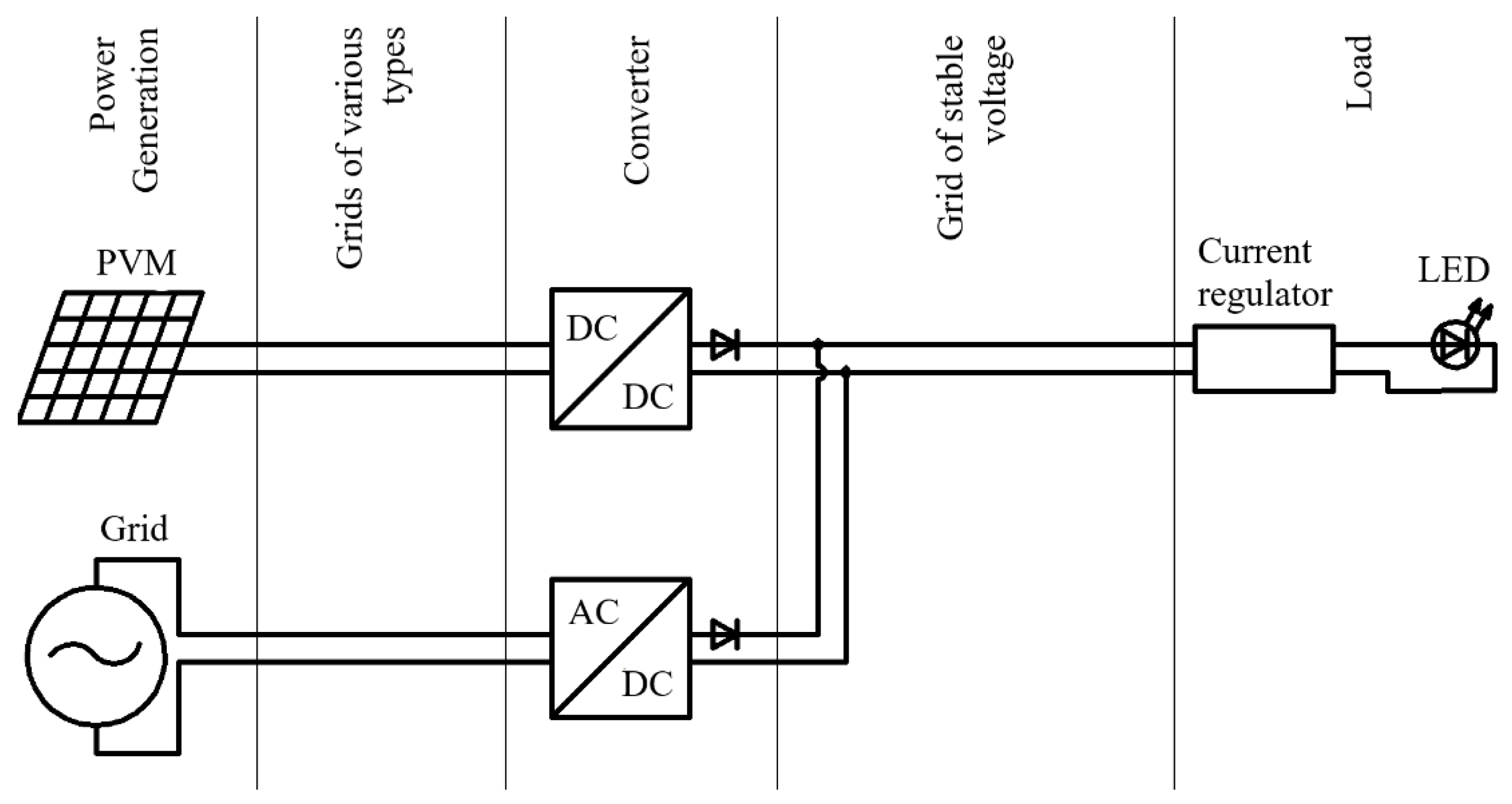
One of the universal schemes is shown in
Figure 1 [
15]. On its basis, a photovoltaic LED lighting system was developed and manufactured.
When the incoming solar radiation flux is sufficient to power the light sources, the power comes from the PVM. When the incoming solar radiation and the production of PVM decrease, the lack of energy is compensated by using a mains power supply (AC/DC) connected to an electrical grid.
The circuit uses step-up and step-down converters with voltage and current stabilization. This allows us to match devices with different levels of voltage and current, which significantly expands the possibilities for using different generators and loads.
The voltage stabilizer at the output of the PVM operates in a wide range of input voltage. Its task is to increase the power take-off from the PVM in comparison with the direct connection of the PVM to the grid at an equal voltage. The current stabilizer at the input of the lamp provides the current operation mode of the LEDs. Diodes protect against power flows between generators at voltage deviations in various operating modes.
An electrical circuit with additional sensors was developed for conducting experimental studies (
Figure 2). This scheme uses a parallel connection of LED lines.
The operating voltage of individual LED lines is about 35 V and is only slightly lower than the maximum voltage of most step-up converters (36…40 V). For the development and wide distribution of such systems, it is desirable to use a higher voltage. This will reduce losses. It is planned to increase the voltage to the voltage of four lines connected in series (140 V). It is possible to use any other voltage level corresponding to the micro-networks in which the system will function [
24,
25,
26].
Table 1 shows the list of equipment of the experimental system.
The study of the operating modes of the LED lighting system requires the use of a device for monitoring parameters. Such a device was developed on the basis of the Arduino Mega (
Figure 3). It allows us to obtain information about the currents and voltages in the LED lighting system and the incoming flow of solar energy. The SD card stores collected data.
The autonomous parameter monitoring system includes:
PCB with a microcontroller;
Digital seven-segment indicator for visual continuous monitoring of the system operation parameters;
Membrane keyboard for switching modes and displayed information;
Real-time clock for logging the time;
Memory card module for interaction of the microcontroller with the SD card;
Current and voltage sensors INA226 for converting electrical parameters of the system into data;
Backup power source based on a lithium-ion battery for uninterrupted operation of the system when the network and/or PVM are disconnected.
The system logs data with an interval of one second.
Current sensors and voltage sensors measure the operating modes of the circuit (
Figure 2). Each element of the INA226 is a current sensor and a voltage sensor [
27] (
Table 2). In the diagram, they are presented as separate elements in the block. Sensors 1 and 2 measure the parameters before and after the PVM converter, sensor 3—after the AC-DC power supply, sensors 4 and 5—before and after the LED load current stabilizer.
As the INA226 uses an external shunt to measure current, after its installation, calibration was performed using a UNI-T model UT61E multimeter [
28].
The FuehlerSysteme eNET International pyranometer GSM/O-U10 model is used to measure the incoming flow of solar radiation [
29]. The analog output of the pyranometer is connected to the ADC of the monitoring device.
The metrological characteristics of the devices used are given in
Table 2.
3. Results
The developed modular LED lighting system with the parallel power supply from the PVM and the power grid has passed a number of field studies on the territory of the Federal Scientific Agroengineering Center VIM, Moscow, Russia (
Figure 4). For the experiments, a minimum module was implemented, consisting of one standard lamp with a power of 36 W and a PVM with a power of 20 W. In general, when choosing the power of the PVM for such a system, it is necessary that the output power of the PVM completely covers the load power at maximum output. This will ensure high values of the PVM efficiency. At the same time, the capacity of the PVM should be selected by taking into account the technical characteristics and climatic operating conditions of the system [
30].
It is also important to correctly select the load for developed systems. Buildings with rooms where artificial lighting is necessary during the working day seem to be the most optimal. As an example, they can be warehouse complexes for agricultural holdings, poultry farms, livestock buildings, mushroom farms, shopping centers, and underground passages. Recently, urban plant factories have also been gaining popularity, where cultivation is carried out indoors under artificial irradiation. In such factories, the use of LEDs in irradiation installations is a nonalternative option, as it is necessary to achieve high energy efficiency due to the precise selection of radiation spectral composition for the grown crop [
31].
The system has shown its efficiency according to the schedule from 10 to 18 h on working days for one month. Operation data of the system during the period of experimental studies are presented in
Figure 5,
Figure 6 and
Figure 7. The module was directed to the south and installed at an angle of 45° to the horizon. The orientation of the module did not change during the entire study period. The pyranometer during the experiment was located at the same angle and azimuth as the photovoltaic module involved in the research, namely, the tilt for solar irradiance measurement was 45 directed to the south, and the latitude of measurement location was 55.7249 N.
For a clear demonstration of the system’s operation at different intensities of incoming solar irradiation (SI), the article presents the system’s performance indicators on one of the days with variable clouds (
Figure 5). According to these data, it is possible to evaluate the operation of the system both in clear weather and in cloudy conditions.
As noted above, the power flow from the PVM and from the power grid is regulated by the voltage level at these sources. The operating voltages on the system elements on one of the days of field studies are shown in
Figure 6.
The figure shows how the voltages change with fluctuations in the power generation of a photovoltaic module. Despite the decrease in the voltage at the output of the PVM converter below the voltage at the output of the grid converter under the conditions of a SI intensity decrease, the power from the PVM continues to flow to the LEDs, which is shown in the graph in
Figure 7. This is explained by the fact that, depending on the flowing current, the voltage drop on the Schottky diodes VD1 and VD2 changes.
At the same voltage after the diodes, different voltages are set before the diodes. The difference depends on the current ratio of the power coming from the network and from the PVM to the lamp. In addition, the oscillatory processes are observed, in which the values of the voltages before and after the PVM converter fluctuate significantly without correlation with changes in the intensity of the incoming SI. It is assumed that it is possible to avoid the oscillatory processes or reduce their magnitude by selecting the smoothing capacitors.
Let us take a closer look at the system power indicators (
Figure 7). In any time interval, including at a low level of SI arrival, all the energy generated by the PVM is consumed on the LEDs (not counting conversion losses), and its lack is compensated by network energy through the power supply unit. At the same time, exactly the amount of energy that is necessary to compensate for the missing power for the operation of the lighting system in the nominal mode is consumed from the power grid. The power received by the LED strip is 36 W and is kept relatively unchanged.
In cloudy conditions, the arrival of SI decreases and the efficiency of the boost converter, which takes power from the PVM, decreases (
Figure 5 and
Figure 8).
Based on the data obtained, it can also be concluded that the step-up converter works together with the PVM with high efficiency at a solar radiation intensity above 100 W/m
2. With sufficient solar radiation, the conversion efficiency reaches about 89%, and only when the SI intensity is below 50 W/m
2, the conversion efficiency is less than 75%, while the power generated by the PVM is less than 10% of its rated power (
Figure 5,
Figure 7, and
Figure 8).
In view of the above-mentioned features, the question remains whether an improvement of the converter at the PVM output is required to increase the efficiency of its operation at low solar radiation intensity. Such an improvement will not be justified, as the converted electric power during such periods is significantly lower in comparison with the nominal operating mode (
Figure 7 and
Figure 8). At the same time, in the nominal operating mode, on the contrary, a schematic revision of the converting device is necessary to increase its efficiency (above 89%).
During a number of experiments, the volt-ampere characteristics (VACs) of a photovoltaic module were taken at different SI (
Figure 9). The characteristics were measured using the load block of resistors and UT61E multimeters.
The obtained VACs were converted into the volt-watt characteristics (VWCs) of the photovoltaic module, shown in
Figure 10.
As can be seen from the figure, the maximum power of the module was about 18 W at an SI intensity of 900 W/m
2. Immediately after taking the characteristics, the module was connected directly to the lighting system according to the scheme shown in
Figure 2. At the same time, with the use of the monitoring system, its operating parameters were recorded for 30 s. The data of these measurements are shown in
Figure 11. The power taken from the PVM was determined by calculation using the current and voltage sensor S1 (see
Figure 2).
After analyzing the experimental data, several facts can be noted. Comparing the data of the maximum power on the VWC of the PVM (
Figure 10) with the experimental data (
Figure 11), it can be noted that the module in the system operates in a mode close to the maximum power mode (
Figure 12). In absolute values, the decrease in the power taken from the PVM in comparison with the power of the VWC is insignificant. The dotted line corresponds to the ideal (reference) version of the operation of the PVM and the system, when the power take-off from the PVM always goes at the point of its maximum power. The red line is drawn along the points corresponding to the data shown in
Figure 11 and characterizes the actual operation of the UV1 converter (
Figure 2).
For the points shown in
Figure 12, power deviations from ideal operating modes were calculated.
Figure 13 shows these values. The decrease in the power take-off efficiency from the PVM is nonlinear in nature and depends on the SI intensity. The maximum deviations of the real power of the PVM, from the power that could potentially be taken-off in accordance with the VWC, are observed during a strong decrease in the intensity of solar irradiation and a reduction in energy production. It is obvious that at low powers, energy from the PVM is taking-off less efficiently.
The obtained data show that under conditions of high SI intensity and with the correct selection of circuit solutions of the UV1 converter, it is possible to take power close to the maximum power point, using inexpensive converters without the function of searching for the maximum power point. Nevertheless, with a decrease in the SI intensity, the efficiency of the converter decreases, while both the power take-off efficiency (
Figure 13) and the conversion efficiency in the UV1 converter itself decrease (
Figure 7). A significant decrease in the efficiency of the UV1 converter is observed at a low intensity of solar radiation, at which the output is minimal. The question of the expediency of increasing the efficiency of the converter in such modes requires additional study.
4. Conclusions
When looking for ways to reduce the cost of the photovoltaic systems, a simple lighting system was developed that implements the concept of direct connection of DC consumers to DC power supply networks from the PVM using an AC grid. The AC grid in this system made it possible to get rid of circuits with an inverter and storage devices and significantly simplify the system itself. This has a positive effect on reliability and cost. The proposed scheme made it possible to create a lighting system with a parallel power supply and self-regulation of energy flows. At the same time, there is no need to monitor the process, provide various kinds of switching in the circuit, or store energy in supercapacitors or batteries, as with traditional circuits.
A number of experimental studies have allowed us to evaluate the operation of the system in practice and to identify the influence of some factors on the operation of the system as a whole. The LED lighting system showed its efficiency and, most importantly, the efficiency of direct connection of photovoltaic modules to a DC load without additional converters. It is also worth noting the stable and trouble-free operation that the system demonstrated during a month of operation.
The experiments allowed us to evaluate the efficiency of the system. The converter provided highly efficient power take-off from the PVM in modes close to the maximum-power modes without using special logic and maximum power point tracking (MPPT) algorithms. Such an efficient operation was facilitated by the correct choice of the power of the module and the converter for it. In this regard, it can be argued that a conventional converter in parallel mode with a properly selected circuit and parameters can provide highly efficient operation of the system without using more expensive MPPT devices.
Despite the significant decline in PVM prices over the past decades, photovoltaic technologies need developments to increase the efficiency and reduce the cost of systems based on them. In this regard, the developed technology of direct use of solar energy for powering DC consumers with parallel operation from the grid allows us to take a step toward reducing the cost of generated energy and improving the reliability of the power supply. This takes us one step closer to the widespread use of solar energy with the use of photovoltaic converters.
Therefore, the developed technology for the direct use of solar energy to power DC consumers with parallel operation from photovoltaic modules and the AC network makes it possible to realize the advantages of various technologies through the use of a hybrid network. It should be noted that any other DC load can be used instead of the LED load. Hybrid networks are becoming a necessary element on the way to increasing efficiency and reducing the cost of products at various agricultural facilities, the power supply of which is partially carried out from PV modules.


 ,
, 


