Article

Research on the Resistance Reduction Law of Self-Excited a Resonant Circular Arc-Surface Bulldozing Plate Based on the Discrete Element Method

1
College of Vehicle and Traffic Engineering, Henan University of Science and Technology, Luoyang 471003, China
2
State Key Laboratory of Intelligent Agricultural Power Equipment, Luoyang 471003, China
3
College of Agricultural Engineering, Henan University of Science and Technology, Luoyang 471003, China
*
Author to whom correspondence should be addressed.
Agriculture 2023, 13(10), 1880; https://doi.org/10.3390/agriculture13101880
Submission received: 24 August 2023 / Revised: 14 September 2023 / Accepted: 22 September 2023 / Published: 26 September 2023

Abstract

:
We explore the mechanism and law of reducing the resistance of soil cutting tools by achieving the self-excited vibration mode through the modification of the soil-engaging surface spectrum. Around the fundamental resonance point of the soil, and superimposing geometric waveforms of different spatial frequencies and amplitudes on the basis of the circular arc surface base directrix, 18 bulldozing plate models with different soil-engaging surface spectrum structures were designed and manufactured. By conducting a discrete element method (DEM) simulation of the working process of the bulldozing plate and comparing the working resistance of the soil-engaging components with the results of the soil bin test, the microscopic process of soil disturbance was further revealed from the perspective of simulation. The results indicate that the self-excited vibrating circular arc-surface bulldozing plate could effectively improve the resistance reduction effect during the operation around the resonance point. With this model, the average error of the horizontal working resistance was 7.52%, and the average error of the vertical working resistance was 21.71%. The analysis of the soil microscopic disturbance process by DEM simulation further verified the correctness of the macroscopic test results. The research work has an important reference value for both the vibration resistance reduction design of soil cutting tools and resistance reduction design of soil-engaging surfaces’ geometric structure modification.

1. Introduction

Soil cutting operation is the main form of human production practice [1,2]. It not only includes various forms of soil cultivation in the agricultural field, but also soil excavation, pushing, shoveling, drilling and other operation methods in project construction of farmland, water conservancy, roads, geological exploration, construction, forestry and military projects. In the future, it will inevitably become an important form of production practice in the field of planetary exploration [3]. During the working process of the soil cutting component, the power consumed to crush, cut, turn or move the soil accounts for approximately 40–60% of the effective power of the host [4]. Therefore, reducing the working resistance and energy consumption of various types of soil-engaging components during the tillage process has significant potential to be explored and holds important practical significance.
Among the proposed soil cutting resistance reduction measures, modifying the geometric structure of the cutting tools is an important approach to reducing the working resistance [5]. Classic soil tillage dynamics and cutting tool structural design studies have produced abundant research results. The design and optimization of the related soil cutting tools’ geometric structure mainly include the geometric shape of the soil-engaging surface, the type of shovel tip, cutting angle and longitude–depth ratio [6]. Among them, the modification of the macroscopic geometric structure of the soil-engaging surface to achieve resistance reduction has attracted our attention. This method does not require the use of external energy sources and auxiliary devices and has a significant resistance reduction effect. Compared to conventional soil cutting tools, the resistance reduction rate is generally greater than 10% [7,8].
The vibration mode also has an efficient resistance reduction capability [9]. Whether it is forced vibration or self-excited vibration, both methods utilize the periodic reciprocating mechanical characteristics of the vibration phenomenon and the granular characteristics of soil materials, causing the soil to be cut to be quickly loosened and achieve the purpose of resistance reduction [10,11]. Compared with forced vibration, self-excited vibration has no additional excitation mechanisms, which can reduce costs while loosening the soil better and increasing the loose soil area at the bottom [12]. Related research related to forced vibration and self-excited vibration mainly focuses on the forms of mechanisms that generate vibration and the working methods of tools [13,14], vibration frequency and amplitude parameters [15,16], and working resistance or energy consumption law [17,18].
The above two methods can reduce the working resistance to a certain extent, but due to their more or less complicated processing technology and weak adaptability, they have certain difficulties in their application [19]. This work combines the improvement in the geometric contour structure of soil-engaging components and self-excited vibration technology in vibration resistance reduction to conduct related research. We directly constructed an excitation spectrum on the soil-engaging surface to achieve self-excited vibration during the soil cutting process, and introduced the resonance effect to improve the soil vibration effect and broaden the vibration frequency range, thus achieving better resistance reduction objectives. The feasibility of this self-excited resonance resistance reduction method was verified by previous soil bin tests [20]. To further reveal the law and reason why the soil-engaging surface spectrum shows better resistance reduction mechanical properties in the process of soil cutting, this paper first built a model of the interaction between the bulldozing plate and soil using DEM software, and then conducted cutting resistance simulation tests and soil bin tests. The test results were compared to determine the reliability of the simulation model. Finally, a simulation was used to analyze the mechanical behavior and particle motion of soil particles interacting with the self-excited vibration circular arc-surface bulldozing plate and circular arc-surface bulldozing plate, respectively. We aim to achieve the coordination between the microscopic disturbance processes and its internal interaction mechanisms from a simulation perspective and using the macroscopic test results from soil bin, providing theoretical and technical support for the promotion and application of this technology.

2. Materials and Methods

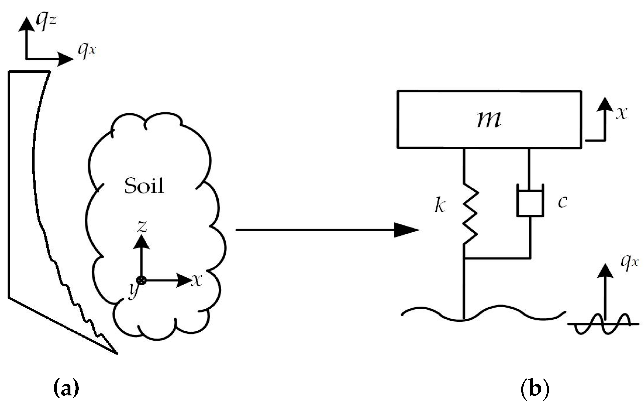
2.1. Vibration Cutting Model

The bulldozing plate–soil vibration cutting model is shown in Figure 1. This model considers the soil as an elastic body with a certain degree of stiffness and damping.
According to Newton’s second law, the differential equation of motion of the system in the x-direction can be obtained as:
m x .. + c x . + k x = c q . x + k q x
where m is the soil mass, kg; k is the stiffness, N/m; c is the damping coefficient, N∙s/m; qx is the horizontal excitation displacement of the cutting component, m; and x is the horizontal displacement of the soil, m.
According to the complex exponential method, let q x ( t ) = a e j ω t (ω the excitation frequency of the tool to the soil, rad/s); then, q . x ( t ) = a ω j e j ω t . Assume that the solution of the equation is x ( t ) = B e j ω t ; then, x . ( t ) = B ω j e j ω t and x .. ( t ) = B ω 2 j e j ω t . Substituting into Formula (1), there is:
B ( m ω 2 + ω j c + k ) = a ( j ω c + k )
Let ω 0 2 = k / m (where ω0 is the natural circular frequency of soil, rad/s), the system damping ratio ζ = c / 2 m ω 0 and the system frequency ratio ζ = ω / ω 0 (in this article, ζ = 0.1). Let β be the amplitude amplification factor. Substitute the above parameters into Formula (2) to obtain the system amplification factor equation.
β = B a = [ 1 + ( 2 λ ξ ) 2 ( 1 λ 2 ) 2 + ( 2 λ ξ ) 2 ] 1 2
The amplitude–frequency characteristic equation in the same form as the amplification factor is:
| H ( j ω ) | x q = [ 1 + ( 2 λ ξ ) 2 ( 1 λ 2 ) 2 + ( 2 λ ξ ) 2 ] 1 2
In the system amplitude–frequency characteristic curve shown in Figure 2, when the ordinate | H ( j ω ) | x q = 1 , there are two intersection points with the curve in the figure, and the abscissas of these two intersection points are λ = 0 and λ = 2 . When the ordinate | H ( j ω ) | x q > 1 , that is, the abscissa λ is in the range of ( 0 2 ) , the vibration amplitude input to the system can be regarded as acting on the soil being cut without attenuation. Accordingly, the amplitude–frequency characteristic curve at the resonance point (λ ≈ 1) will obtain the maximum point. When the ordinate | H ( j ω ) | x q < 1 , that is, the abscissa λ ( 2 , + ) , the excitation effect of the soil by the tool is weakened. These above principle predictions serve as the foundation of this study.

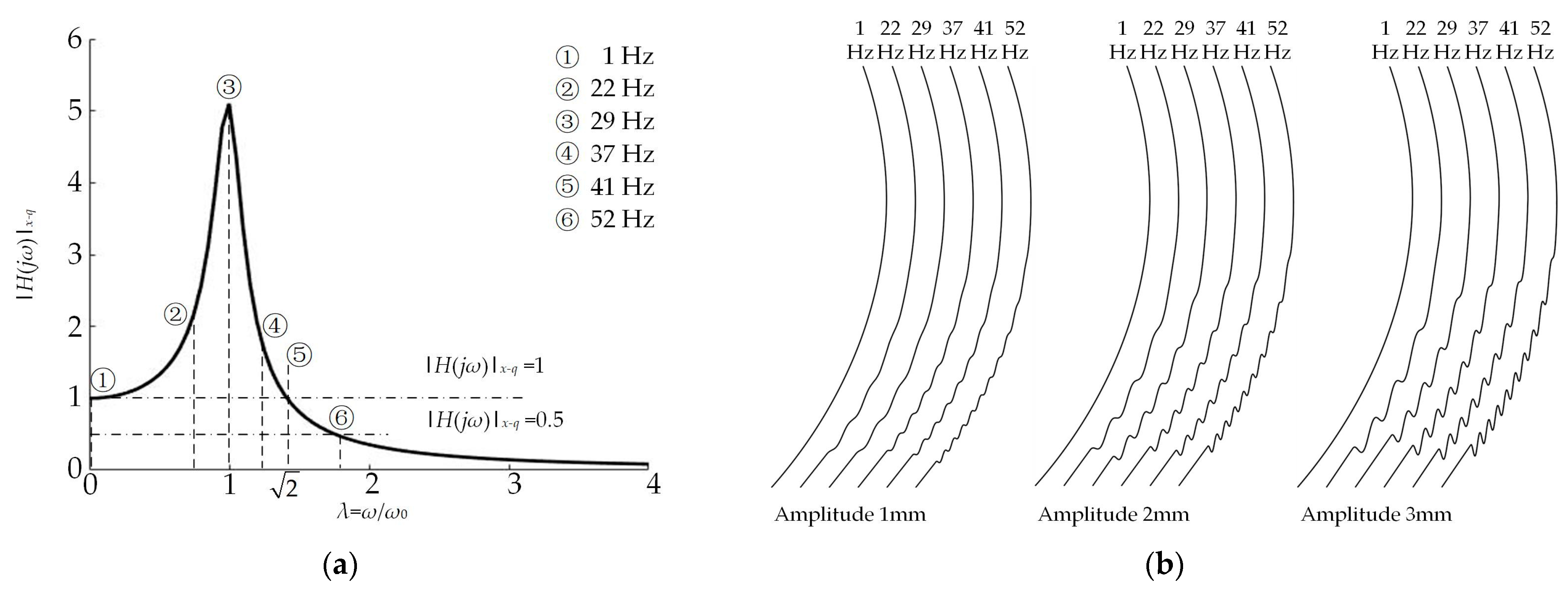
2.2. Soil Natural Frequency

To substantiate the aforementioned viewpoints, it is first necessary to accurately obtain the natural frequency of the soil. Since the physical parameters of the indoor soil bin are relatively stable and easy to control, the natural vibration characteristic parameters are relatively pure. Therefore, this work used the hammering pulse excitation-free attenuation vibration method to conduct testing on the vibration frequency of the soil in the soil bin. Specifically, the acceleration signals of each measuring point were obtained by the DH5902 data acquisition instrument (Jiangsu Donghua Testing Technology Co., Ltd., Nanjing, China) and IEPE acceleration sensor, and the received time domain signals were processed by the DHDAS analysis system. Finally, the mean value of the first-order natural vibration frequency in the x-direction of the soil bin was 29 Hz, and the standard deviation was 1.461 [21]. Other high-order frequency vibration signals in the test results were weak and the distribution of peak points was uneven. As a result, the subsequent analysis and study are exclusively centered around the fundamental frequency.

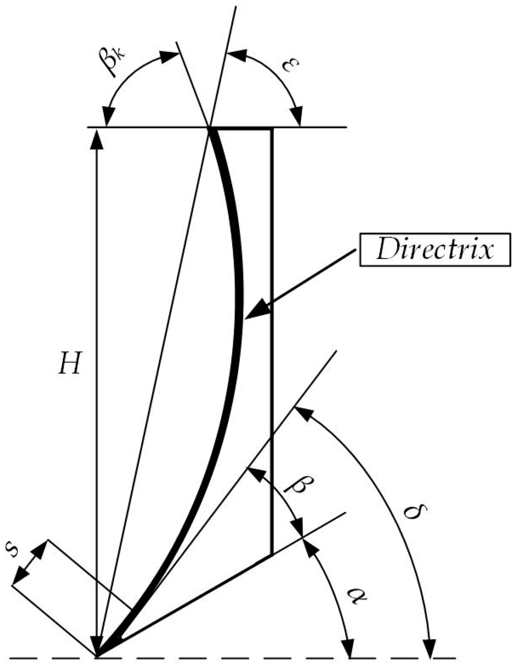
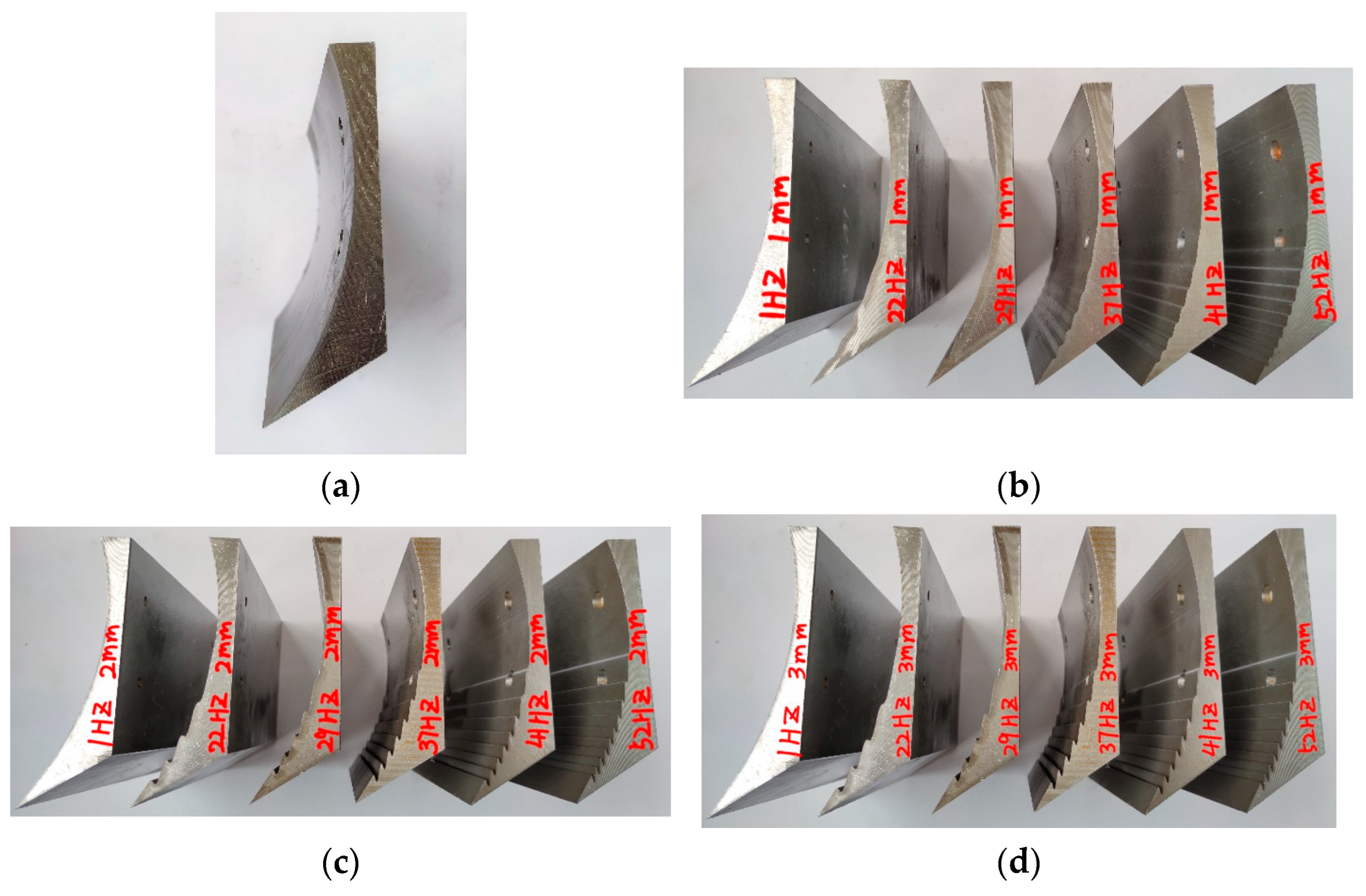
2.3. Design and Manufacture of the Bulldozing Plate Model
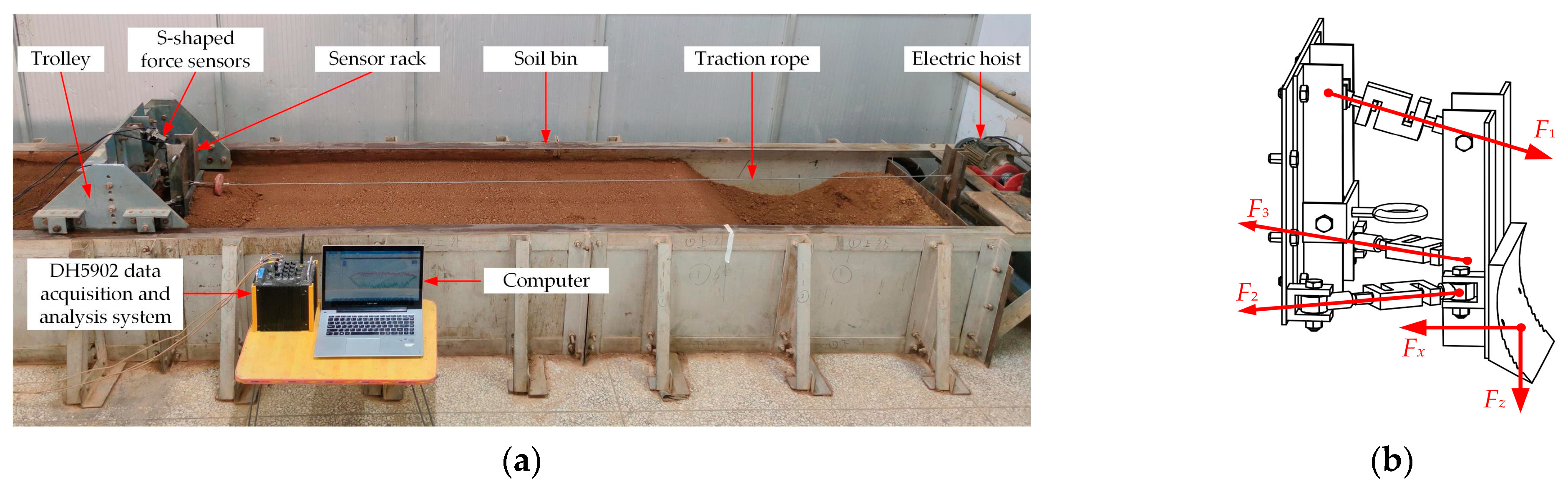
The classical structure parameters of a bulldozing plate shown in Figure 3 mainly include the height H, the soil-engaging surface directrix or directrix curvature radius R, the shovel point length S and various angle parameters. The authors’ previous research found the directrix form exerts a substantial influence on the resistance reduction effectiveness of the bulldozing plate [22]. In this paper, the common circular arc surface in engineering was selected as the base for research, and the structure of the soil-engaging surface spectrum was generated by superimposing the geometric excitation frequencies on the soil-engaging surface of the circular arc surface base.
The general directrix equation expression of this structure is:
f ( x ) = F ( x ) + i = 1 l A i sin ( ω i t + φ i )
Since ωi = 2πfi = 2πuni = 2πnix/t, the above formula can be further written after transformation:
f ( x ) = F ( x ) + i = 1 l A i sin ( 2 π x n i t + φ i )
where F(x) is the directrix equation of a circular arc surface; Ai is the amplitude of the spatial spectrum, mm; φi is the phase of the spatial spectrum, °; ωi is the excitation frequency of the spatial spectrum to the soil, rad/s; ni is the geometric frequency of the spatial spectrum, m−1; and i is the number of levels (this article only studies a single-frequency spectrum; so, i = 1).
The general equation of the base circular arc curve in Formula (4) is:
y = x 2 220.326 x + 10364.136 + 101.804 x [ 0 , 155.3 ]  
Combined with the analysis results in Figure 2, a total of six impact frequency test points were selected. The locations of all frequency points are shown in Figure 4a, and the sizes of all frequency points are shown in Table 1. Considering the size and scaling ratio of the test bulldozing plate, three levels of spatial excitation wave amplitudes were selected, namely, 1 mm, 2 mm and 3 mm. Changes in the phase will change the penetration angle of the soil-engaging surface, thereby affecting its penetration performance and resistance reduction performance. For convenience, we chose to set all phase angles to zero.
Once the working speed of the cutting tool was determined, the values of the spatial excitation frequency were calculated. Due to the upper half of the directrix not having an excitation effect and only providing the effect of turning the soil, the upper half used a circular arc directrix. The directrix equations and directrix collections of the soil-engaging surface spectrum are shown in Table 1 and Figure 4b, respectively.
Combining Table 1 and Figure 3 with the design parameters, 19 bulldozing plates were designed in equal proportions. The geometric parameters of each model sample are shown in Table 2. Q235 steel was utilized as the material for the bulldozing plates, and the blade after processing is shown in Figure 5.

2.4. Soil Bin Test

The overall size parameters of the inner contour of the test soil bin were 6 m in length, 1.2 m in width and 0.6 m in soil depth. As in Figure 6a, the trolley with a bulldozing plate was pulled by the electric motor through the wire rope and driven horizontally on the soil bin track. The force measuring element was composed of three S-shaped force sensors with ball-and-hinge structures at both ends, forming a three-dimensional force system, as shown in Figure 6b. A DH5902 data acquisition instrument and the DHDAS signal analysis system were used for data acquisition and processing, respectively.
The test soil was cinnamon soil. To ensure the same state of the test soil and enhance the comparability of the test data, the soil was pretreated by watering, subsoiling and compaction before each test, so that the main parameters, such as the soil moisture content and firmness, were controlled within a certain range. The tillage depth of the bulldozing plate was controlled at 30 mm. The test working speed was 0.16 m/s, and the common bulldozing speed was between 0 m/s and 0.7 m/s [23]. The lower working speed was limited by the length of the soil bin, on the one hand, and on the other hand, it was mainly for the successful completion of the effective control and data processing requirements during the test process.

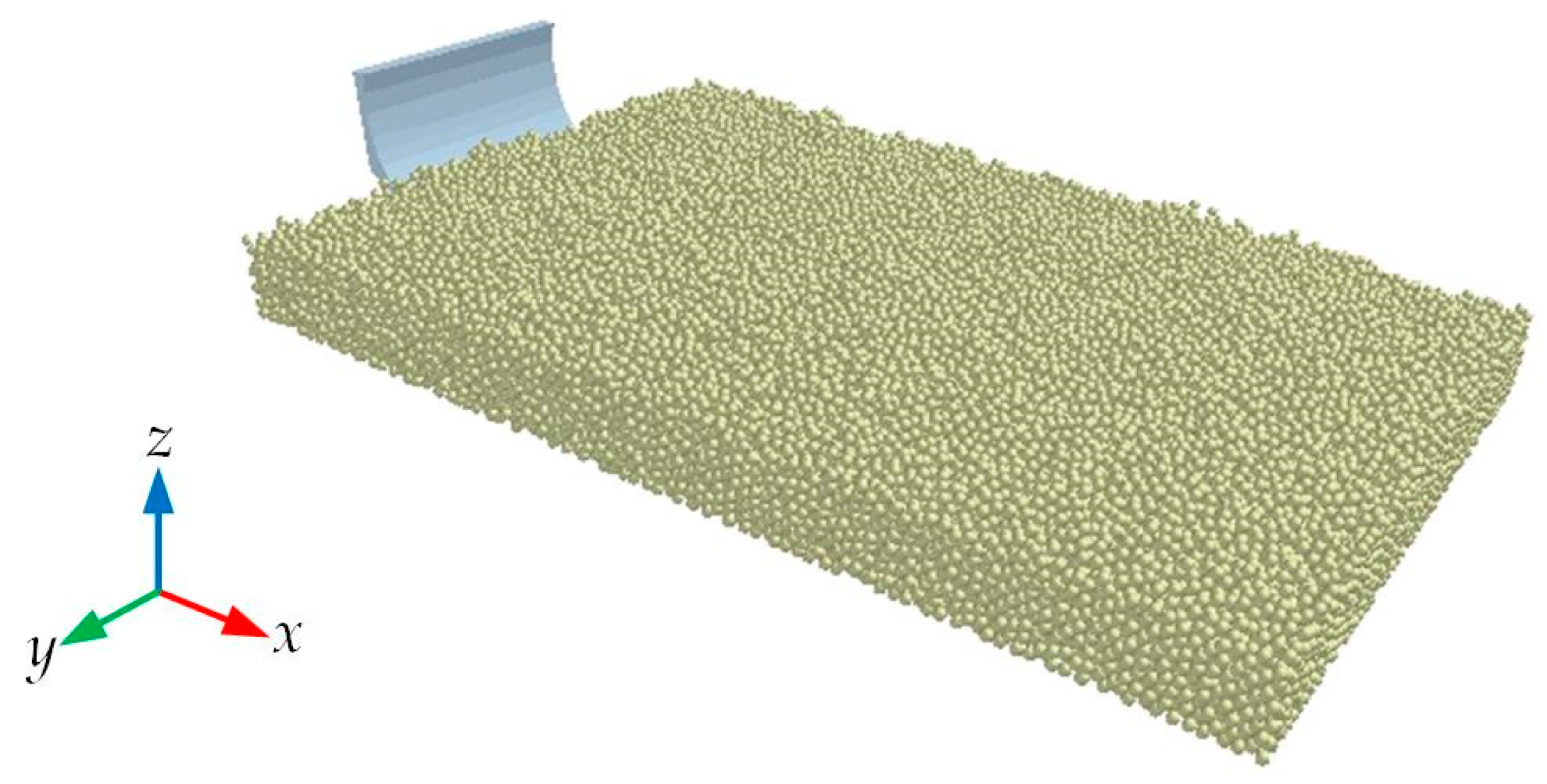
2.5. Discrete Element Simulation

To meet the simulation requirements and avoid the influence of the boundary of the simulation soil bin boundaries on the simulation test, a simulation soil bin measuring 1000 mm in length, 600 mm in width and 220 mm in height was established. The Hertz–Mindlin with JKR model was selected as the contact model, which can be used to simulate the elastic–plastic deformation of the soil during the bulldozing plate operation and the bonding force between the soil due to the presence of water [24]. To ensure the accuracy of the simulation test, the contact parameters and basic physical parameters involved in the simulation test were determined through parameter calibration tests [25], as shown in Table 3.
To ensure the accuracy of the simulation results, the three-dimensional model of the bulldozing plate was saved in the ‘.igs’ format in a 1:1 ratio and imported into the EDEM2020 software (EDEM2020, Tory, MI, USA). After adjusting the position of the bulldozing plate, the bulldozing plate–soil interaction model shown in Figure 7 was constructed. In the simulation environment, the cutting depth was set to 30 cm and the working speed was 0.16 m/s. To ensure the continuous movement of the soil particles during the cutting process, the Rayleigh time step was 1.13 × 10⁻³ s. Through the simulation test, the cutting situation of the bulldozing plate to the soil can be obtained, and the real-time data of the resistance of the bulldozing plate can be derived from the EDEM post-processing tool, and the average value can be calculated.

3. Results and Discussion

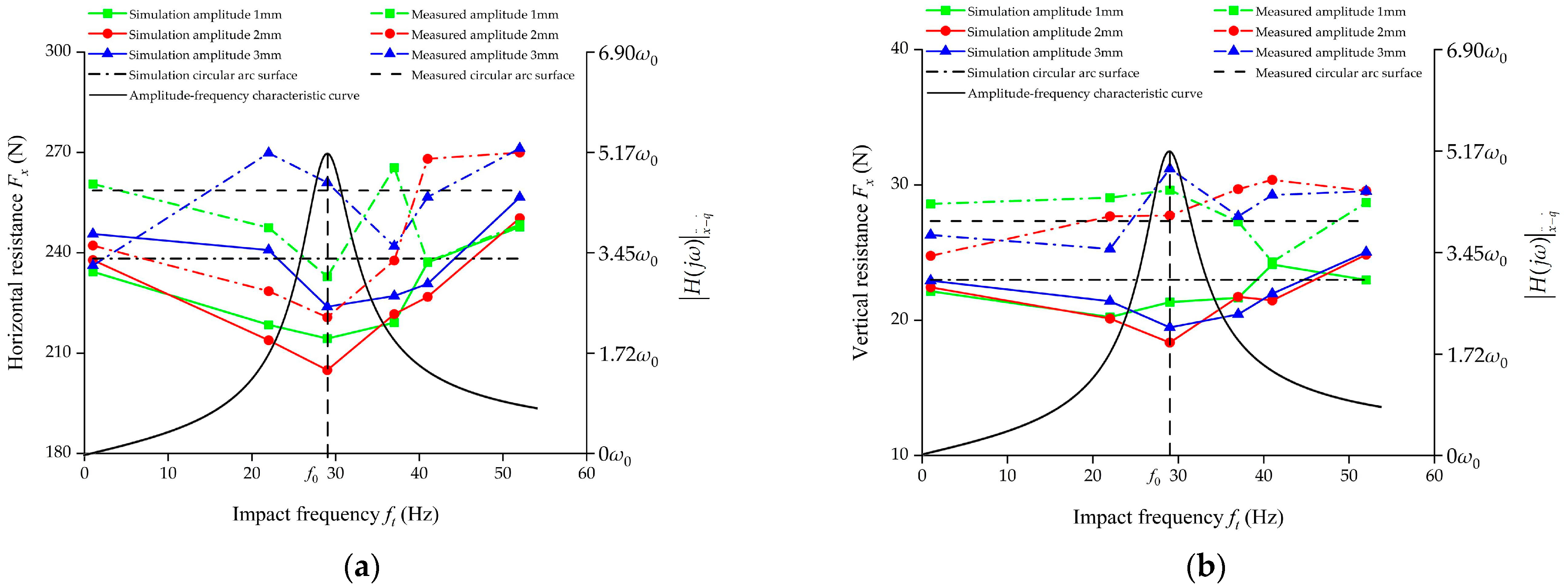
3.1. Comparative Analysis of the Working Resistance

All level combinations of the experimental factors in Table 4 were tested, and three repeated tests were conducted for each bulldozing plate model. The comparison of the test results between the measured working resistance of the soil bin and the simulated working resistance is shown in Table 5. The table distinctly shows that the vertical working resistance of the test bulldozing plate is substantially lower than the horizontal working resistance. Consequently, a more detailed analysis will be dedicated to the horizontal resistance.
To more intuitively analyze the influence of various factors on the working resistance of the bulldozing plate, according to the data presented in Table 5, we drew the line charts of the working resistance shown in Figure 8. The theoretical curve of the acceleration–velocity amplitude–frequency characteristic is also drawn in the figure, which is used to compare and verify the resistance reduction ability of the self-excited vibration bulldozing plate [26].
From Figure 8a, it can be seen that the variation trend of the horizontal working resistance obtained from the soil bin test and simulation test was basically the same, both showing that the resonance point sample had the best resistance reduction effect. On both sides of the resonance point, regardless of whether the frequency increases or decreases, the corresponding model sample had a relatively increasing trend of horizontal working resistance. Among them, the relative error of horizontal resistance obtained from the soil bin test and simulation test is the smallest at an amplitude of 1 mm and a frequency of 41 Hz, which is 0.07%. The relative error of the two is the largest at an amplitude of 1 mm and a frequency of 37 Hz, which is 17.44%. The average relative error of the horizontal resistance under various working conditions was 7.52%. In general, the variation trend of the horizontal working resistance with the frequency obtained from the simulation and actual measurements was in substantial accordance with the convex theoretical resonance curve. Both the simulation and actual measurement results show that the bulldozing plate model with an amplitude of 2 mm and a frequency of 29 Hz had the best resistance reduction effect.
Figure 8b reflects the consistency between the variation trend of the vertical working resistance in the simulation environment and the results of the soil bin test. While obtaining a relatively low horizontal working resistance, the self-excited vibration circular arc-surface bulldozing plate also obtained a relatively low vertical working resistance. However, at a frequency of 29 Hz, amplitude of 2 mm and frequency of 29 Hz, amplitude of 3 mm, the relative errors between the simulated and measured vertical resistance values were relatively large, at 33.85% and 37.6%, respectively. Overall, the average relative error of the vertical resistance under each working condition was 21.71%. A slight decrease in the vertical resistance is beneficial for reducing the frictional force between the soil and the tool, as well as to improve the soil disturbance state. This is because the lower vertical resistance allows the bulldozing plate to penetrate the soil more easily upon contact, facilitating a better soil dispersion and improving the soil plasticity and uniformity of the soil during the operation of the bulldozing plate. In addition, the special frequency spectrum structure of the self-excited vibration circular arc-surface bulldozing plate can change the movement mode of the soil along the soil-engaging surface from sliding contact to rolling contact. This change significantly reduces the adhesion and friction between each other, thereby reducing the total working resistance.
Taking the measured working resistance of the soil bin as the verification standard, a DEM cutting model was established based on the measured soil physical parameters in the soil bin. The error between the simulated working resistance and the measured resistance of the soil bin was relatively small, and it is displayed within an acceptable range with the working resistance as the verification indicator, indicating the matching and applicability of the DEM model prediction. However, due to the presence of residual impurities, such as grass roots on the soil surface, despite the treatment in the soil bin test conditions, and considering the significant human involvement during the soil bin test process, larger errors may occur in certain working conditions. Overall, the results obtained by the two methods are basically consistent in the effect of tillage mechanics, indicating the accuracy and reliability of the soil contact model selection and simulation parameter setting in the DEM cutting model.

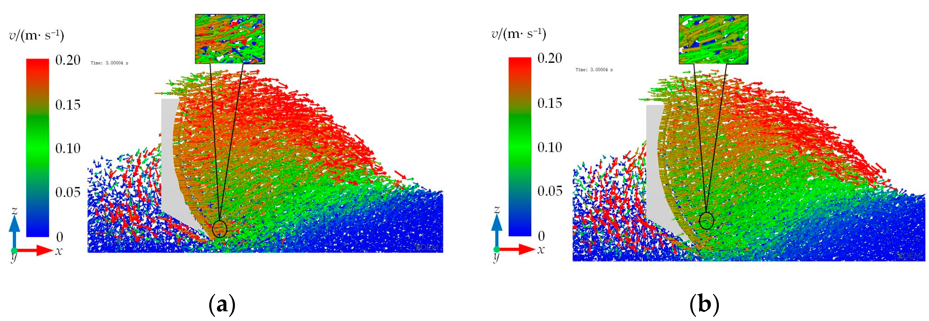
3.2. Microscopic Mechanism of Soil Disturbance

3.2.1. Microprocess Analysis of the Overall Soil Disturbance

Based on the establishment of the DEM model, according to the test results of the simulation cutting test, the microscopic action process of the self-excited vibration circular arc-surface bulldozing plate with the best resistance reduction effect (amplitude of 2 mm and frequency of 29 Hz) and the circular arc shovel on the soil was analyzed. The schematic diagram of the soil movement at two different times in the complete process of initial contact with the soil to stable advance in the soil during the cutting simulation of the bulldozing plate is shown in Figure 9. The velocity change in the soil particles is represented by a color strip, with the color changing from blue to red indicating a gradual increase in velocity. A positive velocity value represents that the velocity of the soil particles is consistent with the forward direction of the bulldozing plate.
Combined with Figure 9a,b, it can be seen that, when the bulldozing plate just enters the soil at 0.6 s, the soil at the front end of the blade surface is in a state of accumulation. In this state, most of the soil climbs upward along the soil-engaging surface, while a small portion of the soil moves forward under the compression of the blade surface. At this moment, the soil at the front end of the bulldozing plate produces a certain degree of arching fluctuation. This arching fluctuation is the result of the compression of the upper layer of soil to the lower layer of soil, and the downward sliding of some upper layer of disturbed soil along the lower layer of soil. From Figure 9c,d, it is evident that, when the working time of the bulldozing plate is 3.0 s, the soil is almost completely piled up at the front end of the soil-engaging surface, and the accumulation of the soil at the front end of the soil-engaging surface reaches a basically stable state. In this state, a part of the soil at the front end of the blade surface slides upward along the bulldozing plate and may even fall to the back end of the bulldozing plate. A part of the soil moves forward under the compression of the bulldozing plate, and another part of the upper layer of the disturbed soil slides downward or laterally along the lower layer of the soil.

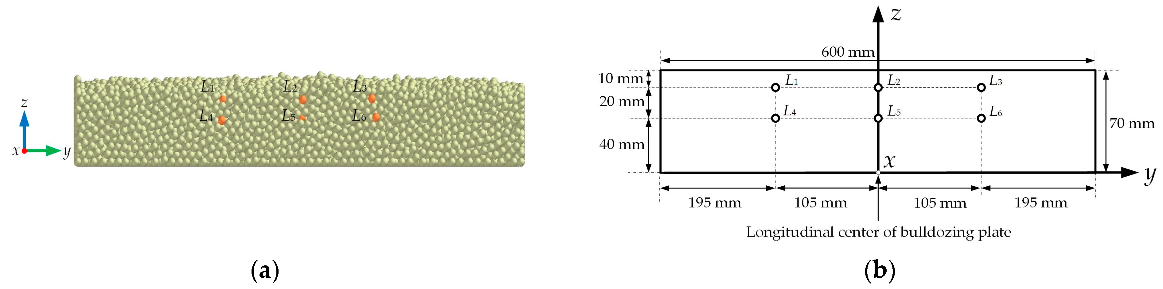
3.2.2. Microprocess Analysis of the Local Soil Disturbance

To observe the interaction mechanism between the bulldozing plate and the soil more clearly, the local amplification diagram of the bulldozing plate’s cutting soil process at 3.0 s was created, and the EDEM post-processing tool (Analyst) was used to transform the soil particle movement speed into a vector diagram for analysis. Figure 10 shows the contact vector diagram between the bulldozing plate and the soil particles, where the vector arrow represents the movement direction of the soil particles, the length represents the size of the speed and the color change in the color band is consistent with the above. From the vector diagram of the soil particle motion, it can be seen that there is a significant change in the velocity of the soil particles around the 3.0 s circular arc bulldozing plate. The soil particles in front of the soil-contacting surface are disturbed the most, and the relative velocity is mostly green. The direction of the soil particle motion is basically the same as that of the forward direction, and the distribution is relatively uniform, which can easily cause soil accumulation. At the same time, the soil particle flow velocity of the self-excited vibration circular arc-surface bulldozing plate is obviously better than that of the circular arc-surface bulldozing plate. The velocity flow direction of the soil particles is scattered, and the soil is in a loose state, reducing soil accumulation. It is concluded that this is due to the resonance phenomenon between the self-excited vibrating circular arc-surface bulldozing plate and the soil in the front part, which changes the flow direction of the soil particles, increases the fluidity and disperses the accumulation effect of the particles. The circular arc shovel cannot produce this effect; so, the resistance will be greater than that of the self-excited vibration circular arc-surface bulldozing plate.
Through the above analysis, it can be observed that the particle displacement flow in the simulation test indirectly reflects the changes in the DEM model after being subjected to force; so, this can be used as one of the excellent evaluation methods for bulldozing plate structures. To further understand the movement law and behavior of soil particles and strengthen the comprehensiveness and accuracy of the research, displacement tracking was conducted on the flowability of the disturbed soil particles in front of the self-excited vibration circular arc-surface bulldozing plate and the circular arc bulldozing plate, and the particles triaxial (x, y, z) displacement distance was recorded. According to the change in the displacement coordinate value, the influence of the two shovel surface structures on the displacement of the soil particles was compared as the basis for the resistance reduction in the bulldozing plate.

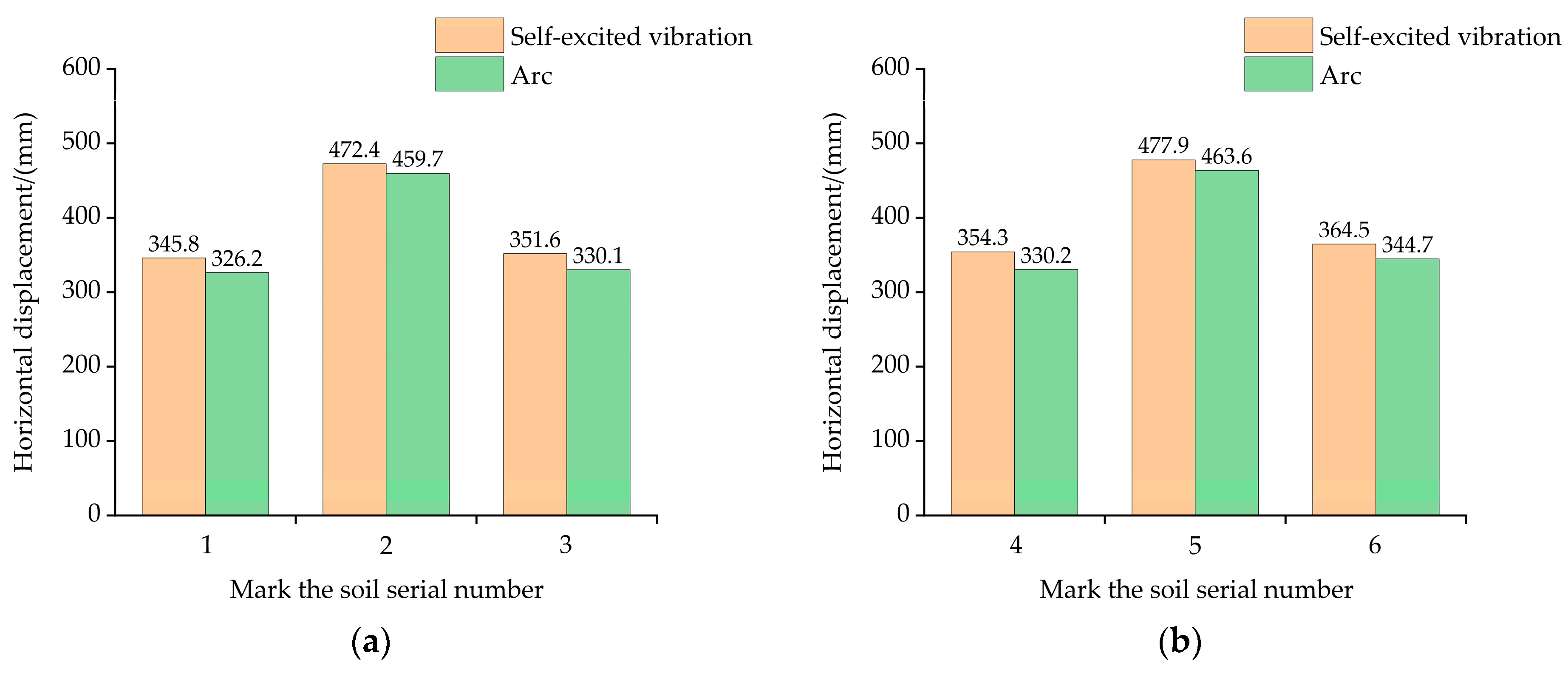
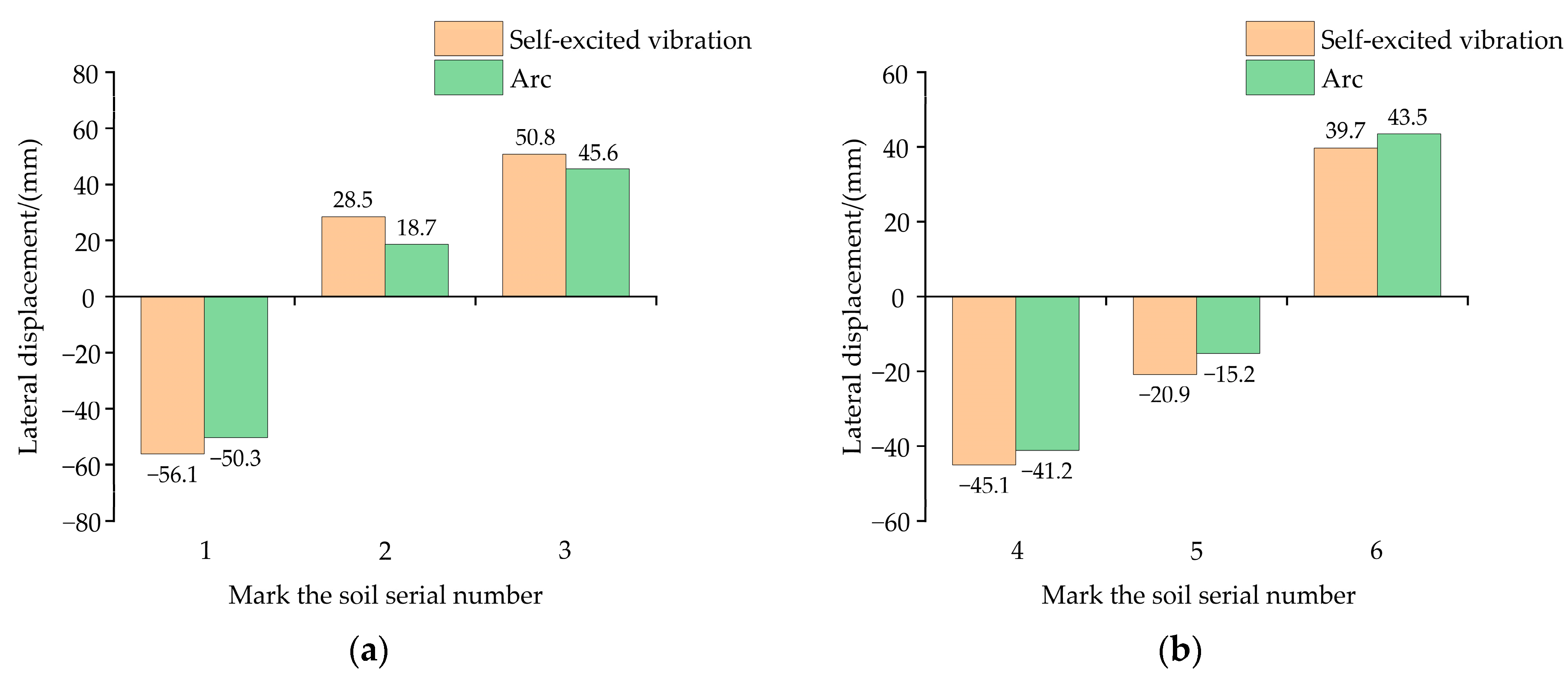
3.2.3. Microprocess Comparative Analysis of the Soil Disturbance Displacement

In the simulation comparison cutting test, it is difficult to capture the displacement of each particle due to a large number of soil particles. Therefore, in order to more comprehensively analyze the movement differences between soil particles in different regions during the disturbance process, soil particles at different depths and different locations were selected for research. Two depth layers were selected, and three positions were selected in each layer; a total of six positions were marked with L1, L2, L3, L4, L5 and L6. The connection lines between the particles were horizontal and vertical. The initial position of the soil particles to be measured is shown in Figure 11a. Among them, the L1~L3 soil particles represent the surface particles of soil; the L4~L6 soil particles represent the bottom layer particles of the soil; and the L1 and L3 columns of soil particles are located at the edge of the bulldozing plate, representing the outer layer of the soil particles. The soil particles of L2 and L5 are located in the longitudinal center of the bulldozing plate, representing the inner soil particles. The specific coordinate positions of the particles are shown in Figure 11b. With a simulation process of 0 s~3.0 s, we used the post-processing function of the EDEM software to export the displacement coordinate values of the particles in three directions during this time period and analyzed the movement of the soil particles.
Comparing and analyzing the x-direction displacement (Figure 12), it can be seen that the horizontal displacement of the bottom soil particles of L4~L6 is positive. Compared with the initial displacement value, the change amount is larger, indicating that the bottom particles mainly move forward. The movement displacement of the L5 soil particles in the middle position is greater compared to the displacement of the soil particles on both sides; the horizontal displacement of the surface soil particles of L1~L3 is also along the direction of the bulldozing plate, but the displacement change value is smaller, indicating that the movement displacement is not as large as that of the bottom soil particles. It is concluded that, when the bulldozing plate enters the soil, the bottom soil is first disturbed by the shovel tip. With the forward movement of the bulldozing plate, the surface soil is also disturbed and begins to move forward. However, the displacement values of soil particles at different depths are not consistent. The bottom disturbance is the most obvious, the soil displacement value is larger, and the surface soil displacement value is smaller. The horizontal displacement of the soil particles in the middle position is larger than that of the soil particles on both sides. The main reason is that the particles on both sides slip laterally due to the accumulation effect of the soil particles, resulting in a smaller horizontal displacement.
Comparing and analyzing the y-direction displacement (Figure 13), it can be seen that the soil particles in the two different layers all move upwards in a vertical and positive direction, but the movement displacement of the marked soil in each layer is different. Among them, the displacement change in the upward movement of the bottom layer particles is small, and the surface layer is larger. The displacement variation of the soil particles in the middle position is larger than that in the outer position. The analysis suggests that the bottom soil is hindered by the upper soil in the upward movement, and there is no large displacement change. Therefore, the bottom soil will form a congestion near the soil-engaging surface, resulting in an excessive resistance. The vertical displacement of the soil particles in the middle position is greater than that on both sides. The main reason is that the soil particles will be squeezed and accumulated on both sides by the bulldozing plate during the cutting process. This accumulation effect prevents the soil particles on both sides from fully contacting with the bulldozing plate during the cutting process. In contrast, the soil particles in the middle position can maintain contact with the bulldozing plate for a long time during the cutting process. Due to the short contact time between the soil particles on both sides and the bulldozing plate, their displacement in the vertical direction is limited. The soil particles in the middle position can be subjected to the action of the bulldozing plate for a long time and climb up along the soil-engaging surface, resulting in a significant change in the vertical displacement.
Comparing and analyzing the z-direction displacement (Figure 14), it can be seen that the lateral displacement of the soil particles in L1 and L4 is negative, while the lateral displacement of the soil particles in L3 and L6 is positive. The lateral displacement of the soil particles in L2 and L5 is relatively complex, with both a positive horizontal movement to the right and a negative horizontal movement to the left. Compared with the initial displacement value, the lateral displacement variation of the bottom layer particles is smaller, while the surface layer particles have a larger variation. This is because the bottom soil is affected by the gravity of the upper soil; so, its movement is hindered by the upper soil to a certain extent. In contrast, the surface soil particles are relatively less constrained, and therefore, the lateral displacement variation is relatively large. The lateral displacement of the soil particles in the middle position is smaller than that of the soil particles on both sides. The main reason is that, during the cutting process, there is more accumulation of the soil particles in the middle position, which limits the lateral displacement between the particles. However, the soil particles at the edge of the bulldozing plate are relatively less constrained, and the particles are relatively loose, which is more prone to lateral displacement.
Comparing the displacement of the self-excited vibration circular arc-surface bulldozing plate and the circular arc surface bulldozing plate in the three axis directions, it can be observed that the structural advantages of the self-excited vibration circular arc-surface bulldozing plate are highlighted. The average displacement in all three directions is better than that of the circular arc-surface bulldozing plate. The average displacement values of soil particles in the x-direction of the self-excited vibration circular arc-surface bulldozing plate and the circular arc-surface bulldozing plate are 394.40 mm and 375.75 mm, respectively. The average displacement values of soil particles in the y-direction are 69.50 mm and 64.40 mm, respectively, and the average displacement values of soil particles in the z-direction are −0.52 mm and 0.19 mm, respectively. This may be due to the vibration excitation force generated by the self-excited vibrating bulldozing plate causing the discrete displacement of the soil particles. This resonance effect can break the friction among the soil particles and reduce the internal resistance, thus promoting the flow of soil particles.
In summary, adopting the form of self-excited vibration and using the resonance effect to construct the spatial frequency spectrum structure of the soil-engaging surface and reasonably modifying the geometric shape of the soil-engaging surface will greatly increase the fluidity of the disturbed soil particles in front of the soil-engaging components, thereby obtaining a lower working resistance and achieving the purpose of reducing resistance and increasing efficiency.

4. Conclusions

By testing the mechanical properties of the soil-engaging surface spectrum of the self-excited vibration circular arc-surface bulldozing plate, the mechanism and law of reducing the resistance of soil cutting tools by modifying the soil-engaging surface spectra to achieve the patterns of self-excited vibration were comprehensively explored. Through the above research, the following conclusions can be drawn:
(1)
The soil bin test and simulation test results both verify the feasibility of the self-excited vibrating bulldozing plate soil-engaging surface spectrum resistance reduction design method based on the resonance effect and the rationality of the structural design. Compared with the simple circular arc-surface bulldozing plate without frequency spectrum design, the self-excited vibration circular arc-surface bulldozing plate can better improve the resistance reduction effect in the cutting process near the resonance point. Under the research conditions, the bulldozing plate model with an amplitude of 2 mm and a frequency of 29 Hz had the best resistance reduction effect.
(2)
The average errors between the horizontal working resistance and vertical working resistance obtained from the simulation model with the corresponding test values are 7.52% and 21.71%, respectively, which verifies the effectiveness of the DEM.
(3)
During the cutting process, the horizontal displacement of the surface soil particles is smaller than that of particles in the bottom layer, while the vertical and lateral displacements are larger than those of the bottom layer. In addition, regardless of the depth of the soil particles, the horizontal displacement and vertical displacement of the soil particles at the longitudinal center of the bulldozing plate are larger than those on both sides, while the lateral displacement is smaller than that on both sides.
(4)
The self-excited vibrating circular arc-surface bulldozing plate with a specific frequency spectrum structure can increase the fluidity of the disturbed soil in front of the soil-engaging surface during the working process. This is due to the self-excited vibration circular arc-surface bulldozing plate resonating with the soil in a certain range ahead. Because the soil material generally has granular characteristics, the soil in the resonance state will be easily broken, which is not only conducive to changing the flow direction of the soil particles and increasing the fluidity, but also conducive to dispersing the disturbed soil in front of the soil-engaging surface and obtaining a lower cutting resistance. It is an important condition for achieving high-efficiency and energy-saving soil tillage, and it is also an important factor to be considered in the optimal design of the vibration soil cutting machine.
This study was mainly aimed at assessing wide-tooth soil tillage components, and the mechanical properties of the narrow-tooth soil tillage components need to be further studied. In addition, for moldboard plough, rotary blade and other tillage components, the contour shape has the characteristics of asymmetry along the tillage direction, and the optimization design method of this three-dimensional, complex soil-engaging surface needs to be further studied.

Author Contributions

Conceptualization, Y.Q. and Z.G.; methodology, Y.Q.; software, J.W.; validation, Z.G. and X.Y.; formal analysis, S.S.; investigation, F.G.; resources, F.Z.; data curation, Y.Q.; writing—original draft, Y.Q.; writing—review and editing, Y.Q.; visualization, Y.Q.; supervision, Z.G.; project administration, Z.G.; funding acquisition, Z.G., J.W. and F.Z. All authors have read and agreed to the published version of the manuscript.

Funding

This work was supported by the National Natural Science Foundation of China (grant numbers 51675163, 52075149 and 51905155).

Institutional Review Board Statement

Not applicable.

Data Availability Statement

Not applicable.

Acknowledgments

We would like to express our sincere thanks to the members of the study group for their hard work.

Conflicts of Interest

The authors declare no conflict of interest.

References

  1. Tong, J.; Moayad, B.Z. Effects of rake angle of chisel plough on soil cutting factors and power requirements: A computer simulation. Soil Till. Res. 2006, 88, 55–64. [Google Scholar] [CrossRef]
  2. Ji, W.F.; Chen, D.H.; Jia, H.L.; Tong, J. Experimental investigation into soil-cutting performance of the claws of mole rat (scaptochirus moschatus). J. Bionic. Eng. 2010, 7, S166–S171. [Google Scholar] [CrossRef]
  3. Ren, L.Q.; Han, Z.W.; Li, J.Q.; Tong, J. Experimental investigation of bionic rough curved soil cutting blade surface to reduce soil adhesion and friction. Soil Till. Res. 2006, 85, 1–12. [Google Scholar] [CrossRef]
  4. Iman, A. A power estimator for an integrated active-passive tillage machine using the laws of classical mechanics. Soil Till. Res. 2017, 171, 1–8. [Google Scholar]
  5. Godwin, R.J. A review of the effect of implement geometry on soil failure and implement forces. Soil Till. Res. 2007, 92, 331–400. [Google Scholar] [CrossRef]
  6. Jia, H.L.; Wang, W.P.; Chen, Z.; Zheng, T.Z.; Zhang, P.; Zhuang, J. Research status and prospect of soil-engaging components optimization for agricultural machinery. Trans. Chin. Soc. Agric. Mach. 2017, 48, 1–13. [Google Scholar]
  7. Zheng, K.; He, J.; Li, H.W.; Diao, P.S.; Wang, Q.J.; Zhao, H.B. Research on polyline soil-breaking blade subsoiler based on subsoiling soil model using discrete element method. Trans. Chin. Soc. Agric. Mach. 2016, 47, 62–72. [Google Scholar]
  8. Soni, P.; Salokhe, V.M.; Nakashima, H. Modification of a mouldboard plough surface using arrays of polyethylene protuberances. J. Terramech. 2007, 44, 411–422. [Google Scholar] [CrossRef]
  9. Wang, Y.; Zhang, D.; Yang, L.; Cui, T.; Zhang, W.; Qi, B.; Li, Y.; Zhong, X. Field performance of an electric–hydraulic control system for vibrating subsoiler with flexible tines. Comput. Electron. Agric. 2020, 172, 105377. [Google Scholar] [CrossRef]
  10. Zhou, D.Y.; Hou, Y.L.; Xin, Y.L.; Wu, B.G.; Ting, J.; Yu, H.Y.; Qi, J.T.; Zhang, J.S.; Zhang, Q. Resistance and consumption reduction mechanism of bionic vibration and verification of field subsoiling experiment. Appl. Sci. 2021, 11, 10480. [Google Scholar] [CrossRef]
  11. Zhang, X.Y.; Chen, Y. Soil disturbance and cutting forces of four different sweeps for mechanical weeding. Soil Till. Res. 2017, 169, 167–175. [Google Scholar] [CrossRef]
  12. Wang, Y.X.; Zhang, D.X.; Yang, L.; Cui, T.; Li, Y.H.; Liu, Y.W. Design and experiment of hydraulically self-excited vibration subsoiler. Trans. Chin. Soc. Agric. Eng. 2018, 34, 40–48. [Google Scholar]
  13. Wang, Y.; Zhang, D.; Yang, L.; Cui, T.; Jing, H.; Zhong, X. Modeling the interaction of soil and a vibrating subsoiler using the discrete element method. Comput. Electron. Agric. 2020, 174, 105518. [Google Scholar] [CrossRef]
  14. Elyas, R.; Yuness, S. Vibratory soil cutting a new approach for the mathematical analysis. Soil Till. Res. 2016, 159, 33–40. [Google Scholar]
  15. Niyamapa, T.; Salokhe, V.M. Force and pressure distribution under vibratory tillage tool. J. Terramech. 2000, 37, 139–150. [Google Scholar] [CrossRef]
  16. Sahay, C.S.; Thomas, E.V.; Satapathy, K.K.; Anthonis, J. Performance evaluation of a novel power-tiller-operated oscillatory tillage implement for dry land tillage. Biosyst. Eng. 2009, 102, 385–391. [Google Scholar] [CrossRef]
  17. Berntsen, R.; Bere, B.; Torp, T.; Aasen, H. Tine forces established by a two-level model and the draught requirement of rigid and flexible tines. Soil Till. Res. 2006, 90, 230–241. [Google Scholar] [CrossRef]
  18. Mouazen, A.M.; Duerinckx, K.; Ramon, H.; Anthonis, J. Soil influences on the mechanical actions of a flexible spring tine during selective weed harrowing. Biosyst. Eng. 2007, 96, 7–18. [Google Scholar] [CrossRef]
  19. Wang, X.Z.; Zhou, H.; Wang, S.S.; Zhou, H.M.; Ji, J.T. Methods for reducing the tillage force of subsoiling tools: A review. Soil Till. Res. 2023, 229, 105676. [Google Scholar] [CrossRef]
  20. Guo, Z.J.; Qiu, Y.Q.; Yan, X.H.; Wang, J.J.; Zhang, Y.; Zhang, P.G.; Zhang, F. Self-Excited-Resonance of Soil-Engaging Surface Spectrum: A New Method of Soil Cutting Resistance Reduction. Agriculture 2023, 13, 1154. [Google Scholar] [CrossRef]
  21. Zhang, P.G. Design and Experiment of Drag Reduction on Self-Exciting Vibrating Soil-engaging Surface of Bulldozing Plates with Parabolic Basement. Master’s Thesis, Henan University of Science and Technology, Luoyang, China, 2022. [Google Scholar]
  22. Guo, Z.J.; Zhou, D.Y.; Zhou, Z.L. Simulation research on mechanical performances of several kinds of cultivating components with different soil-engaging surfaces. J. Mech. Eng. 2010, 46, 71–75. [Google Scholar] [CrossRef]
  23. Du, G. Experiment Research on Adhesion-reducing and Resistance-decreasing Properties of Macroscopic Soil-engaging Surface for Bulldozing Plates. Master’s Thesis, Henan University of Science and Technology, Luoyang, China, 2011. [Google Scholar]
  24. Wu, T.; Huang, W.F.; Chen, X.S.; Ma, X.; Han, Z.Q.; Pan, T. Calibration of discrete element model parameters for cohesive soil considering the cohesion between particles. J. South China Agric. Univ. 2017, 38, 93–98. [Google Scholar]
  25. Qiu, Y.Q.; Guo, Z.J.; Jin, X.; Zhang, P.G.; Si, S.J.; Guo, F.G. Calibration and verification test of cinnamon soil simulation parameters based on discrete element method. Agriculture 2022, 12, 1082. [Google Scholar] [CrossRef]
  26. Yu, Z.S. The comfort of a car. In Automobile Theory, 6th ed.; China Machine press: Beijing, China, 2019; pp. 246–247. [Google Scholar]
Figure 1. Soil vibration cutting model. (a) Actual model; (b) simplified model.
Agriculture 13 01880 g001
Figure 2. Amplitude–frequency characteristic of the single-system model.
Agriculture 13 01880 g002
Figure 3. Diagram of the structural parameters of the bulldozing plate.
Agriculture 13 01880 g003
Figure 4. Directrix design of the soil-engaging surface spectrum. (a) Position distribution of alternative frequencies in the amplitude–frequency characteristic curve; (b) directrix collection.
Agriculture 13 01880 g004
Figure 5. The 19 experiment bulldozing plate samples. (a) Circular arc-surface bulldozing plate; (b) 1 mm amplitude–0 phase self-excited vibration circular arc-surface bulldozing plate; (c) 2 mm amplitude–0 phase self-excited vibration circular arc-surface bulldozing plate; and (d) 3 mm amplitude–0 phase self-excited vibration circular arc-surface bulldozing plate.
Agriculture 13 01880 g005
Figure 6. Testing system of the soil bin and trolley. (a) Soil bin test photograph; and (b) force diagram of the bulldozing plate.
Agriculture 13 01880 g006
Figure 7. The DEM model of the interaction model between the bulldozing plate and the soil.
Agriculture 13 01880 g007
Figure 8. Comparison of the working resistance measurement and simulation results. (a) Horizontal resistance; and (b) vertical resistance.
Agriculture 13 01880 g008
Figure 9. Overall view of the cutting process. (a) Self-excited vibrating circular arc-surface bulldozing plate at 0.6 s, (b) arc surface bulldozing plate at 0.6 s, (c) self-excited vibrating circular arc surface bulldozing plate at 3.0 s, and (d) arc surface bulldozing plate at 3.0 s.
Agriculture 13 01880 g009
Figure 10. Vector diagram of the soil particle movement for the two kinds of bulldozing plates. (a) Self-excited vibrating circular arc-surface bulldozing plate, and (b) arc surface bulldozing plate.
Agriculture 13 01880 g010
Figure 11. The initial position of the soil particles to be measured. (a) The initial position of the soil particles in the model, and (b) schematic diagram of the initial position.
Agriculture 13 01880 g011
Figure 12. Horizontal displacement of the soil particles. (a) Surface soil particles, and (b) bottom soil particles.
Agriculture 13 01880 g012
Figure 13. Vertical displacement of the soil particles. (a) Surface soil particles, and (b) bottom soil particles.
Agriculture 13 01880 g013
Figure 14. Lateral displacement of the soil particles. (a) Surface soil particles, and (b) bottom soil particles.
Agriculture 13 01880 g014
Table 1. Directrix equation of the soil-engaging surface spectrum.
NumberFrequency
Ratio
Impact
Frequency
(Hz)
Working Speed
(m·s−1)
Spatial Geometric
Frequency
(mm−1)
Wavelengths (mm)Directrix Equation
10.03410.160.00625160z = F(x) + Aisin(0.039x)
20.75220.160.13757.3z = F(x) + Aisin(0.864x)
31290.160.181255.5z = F(x) + Aisin(1.138x)
41.25370.160.231254.3z = F(x) + Aisin(1.452x)
51.414410.160.256253.9z = F(x) + Aisin(1.609x)
61.758520.160.3253.1z = F(x) + Aisin(2.041x)
Table 2. Structural parameters of the model bulldozing plate.
ParameterValue
Height of blade (mm)150
Width of blade (mm)240
Cutting angle (°)78
Clearance angle (°)30
Shovel point closed angle (°)48
Skew angle (°)78
Table 3. The basic parameters of DEM.
ParameterValueSource
Soil shear modulus (MPa)3.846Test
Soil bulk density (kg·m−3)1394Test
Soil Poisson’s ratio0.3Calibration
Steel shear modulus (MPa)7900Reference [25]
Steel bulk density (kg·m−3)7850Reference [25]
Steel Poisson’s ratio0.3Reference [25]
Soil–soil recovery coefficient0.45Calibration
Soil–soil static friction coefficient0.56Calibration
Soil–soil rolling friction coefficient0.08Calibration
Soil–steel recovery coefficient0.45Calibration
Soil–steel rolling friction coefficient0.125Calibration
Soil–steel static friction coefficient0.64Calibration
Surface energy of soil for JKR model/(J·m−2)0.37Calibration
Table 4. Table of test factor levels.
LevelFactors
Frequency (Hz)Amplitude (mm)
111
2222
3293
437
541
652
Table 5. Working resistance results of the bulldozing plate test.
NumberFactorHorizontal Resistance (N)Vertical Resistance (N)
Frequency (Hz)Amplitude (mm)Simulation ValueTest
Value
Relative
Error
Simulation ValueTest
Value
Relative
Error
11(1)1(1)234.32260.5810.08%22.1528.622.55%
24(22)1(1)218.47247.4911.73%20.2429.0630.35%
35(29)1(1)214.36232.887.95%21.3429.6227.95%
46(37)1(1)219.13265.4317.44%21.6627.2820.60%
57(41)1(1)237.11237.280.07%24.1224.310.78%
68(52)1(1)247.73248.440.29%22.9828.6919.90%
71(1)2(2)237.81242.191.81%22.4424.769.37%
84(22)2(2)213.85228.536.42%20.1327.6827.28%
95(29)2(2)204.92220.727.16%18.3527.7433.85%
106(37)2(2)221.68237.696.74%21.7329.6926.81%
117(41)2(2)226.83268.0915.39%21.4730.3729.31%
128(52)2(2)250.37269.967.26%24.8529.5615.93%
131(1)3(3)245.63236.18−4.00%22.9326.312.81%
144(22)3(3)240.82269.8110.74%21.4125.2715.28%
155(29)3(3)223.87260.9714.22%19.4731.237.60%
166(37)3(3)227.11241.946.13%20.4427.6726.13%
177(41)3(3)230.72256.6710.11%21.9629.2524.92%
188(52)3(3)256.61271.195.38%25.0329.5315.24%
19Circular arc surface238.27258.637.87%22.9927.3315.88%
Disclaimer/Publisher’s Note: The statements, opinions and data contained in all publications are solely those of the individual author(s) and contributor(s) and not of MDPI and/or the editor(s). MDPI and/or the editor(s) disclaim responsibility for any injury to people or property resulting from any ideas, methods, instructions or products referred to in the content.

