Article

Real-Time Monitoring System of Seedling Amount in Seedling Box Based on Machine Vision

Key Laboratory of Modern Agricultural Equipment and Technology, Ministry of Education of the People’s Republic of China, Zhenjiang 212013, China
*
Author to whom correspondence should be addressed.
Agriculture 2023, 13(2), 371; https://doi.org/10.3390/agriculture13020371
Submission received: 27 December 2022 / Revised: 14 January 2023 / Accepted: 31 January 2023 / Published: 3 February 2023
(This article belongs to the Section Agricultural Technology)

Abstract

:
Conventional mat-type seedlings are still widely used in autonomous rice transplanters and automatically supplying seedling devices suited to conventional mat-type seedlings is difficult to develop. Thus, an autonomous rice transplanter carries at least one person to load the seedling pieces into the seedling box, which has led to an increase in the labor force and low operational efficiency. To solve this problem from another point of view, a machine vision-based system for the real-time monitoring of the seedling amount in a seedling box is developed. This system aims to achieve the monitoring of the fault of seedlings and seedling amount in the seedling box. According to the real-time and accuracy requirements of the image, the image acquisition platform is designed based on a previously developed autonomous rice transplanter. A camera model was developed and camera parameters for correcting the image distortion is obtained. The image processing method and segment method of seedling rows are presented. The algorithms for fault diagnosis and the calculation of the number of remaining seedlings are proposed by image analysis. The software is developed for seedling box fault diagnosis and monitoring the remaining number of seedlings. Field experiments are carried out to test the effectiveness of the developed monitoring system. The experimental results show that the image processing time is less than 1.5 s and the relative error of the seedling amount is below 3%, which indicates that the designed monitoring system can accurately realize the fault diagnosis of the seedling pieces and monitor for the remaining amount of each row. By combining the navigation information, the developed monitoring system can predict the distance from which the remaining seedlings in the seedling box can be planted, which can guarantee remaining seedlings in a seedling box are enough for transplanting until the rice transplanter returns to the supplying seedling site. This implies that one person can provide seedlings for multiple autonomous rice transplanters. This study was limited to supplying the seedling when the rice transplanter passed through the place of the seedling storage situated at the headland. In the future, we decide to conduct a study on path planning of breakpoint endurance so that the rice transplanter can automatically return to the supplying seedling place when the seedling amount in the seedling box is not enough.

1. Introduction

With the transfer of the rural labor force to cities and the increase in young and middle-aged laborers unwilling to engage in agricultural production, autonomous agricultural machinery covering plowing, planting, managing, and harvesting has been developed in China [1] and several runs of field demonstration tests have been carried out. However, it has not yet reached the full coverage of the field and long-term continuous and reliable operations are limited by the complex and dynamic farmland environment [1].
Many studies have been conducted on autonomous rice transplanters [2,3,4,5,6]. Straight line tracking, head-turning, and the automatic splicing of rows have been achieved. The lateral deviation is less than 5 cm, which meets the operating accuracy and agronomic requirements of rice transplanting. However, the automatic device which can load rice seedlings for seedling boxes has not been developed. The rice seedling is still needed to load into the seedling box manually, thus the operation of the autonomous rice transplanters continues to need a manual intervention. The complete autonomous operation of the rice transplanter has not been fully developed. An unmanned transplanter currently carries at least one person to load the seedling pieces into the seedling box. The mat-shaped rice seedling was widely applied in rice transplanting. Since the fresh seedlings is the flexible and easily broken and the seedling tray is needed to be removed before loading the seedling pieces into the seedling box, it is difficult to develop the automatic supplying seedling device. Therefore, automatic supply seedling technology is the common key technical problem facing the existing unmanned transplanter.
Conventional rice seedlings were used in the autonomous rice transplanter, where 20 seedling mats were required to transplant an area of 1000 m2. The seedling box of a six-row rice transplanter can carry 12 seedling mats at one time [7]. This implies that the seedlings have to be supplied during the process of transplanting, which is a problem for the fully autonomous rice-transplanting operation. To solve this problem, a novelty strategy was proposed in [2]. Long mat-type hydroponic rice seedlings were cultivated and no longer require supplying the additional seedlings during the transplanting operation. Meanwhile, the seedling box in a conventional rice transplanter was modified by adding an appendance to carry long-mat seedlings. The long-mat seedling and the modified seedling box were as shown in Figure 1 [2].
To investigate the effect of hydroponically grown long-mat seedlings (HLMS) on rice yields and growth characteristics, a few comparison studies about HLMS and seedlings via the traditional nutritive soil method (CK) were carried out. The growth and yield of long-mat-type hydroponic rice seedlings were surmised to be almost the same as those of ordinary mat-type rice seedlings cultivated in a soil bed [8]. Subsequently, the quality and field growth characteristics of hydroponically grown long-mat seedlings were investigated and a comparison between CK and HLMS was conducted [9]. The results indicated that the yield and benefit/cost ratio of HLMS were equivalent or superior to those of CK. In addition, the seedling quality of HLMS was better than that of CK, which enabled high-yield and high-efficiency rice production. Regrettably, conventional rice seedlings were mostly used in autonomous rice transplanters despite the advantages of the HLMS. The reasons for this need further research.
Based on advanced precision agriculture and Internet technologies, some relatively mature and feature-rich unmanned farm cloud platforms such as the operations center network [10], farm operation platform called Farmer core [11], TELEMATICS portal and mobile applications [12], an IoT-enabled cloud management platform [13], a remote monitoring platform for agricultural machinery [14], an ecological unmanned farm intelligent cloud platform [15], and an intelligent agricultural machinery operation integrated management and monitoring information platform [16] were developed. These platforms, which were online farm management systems in essence, could be used to manage users, agricultural machinery, and farmland information. The index, such as the equipment performance, future crop yield, operating environment quality, and collaborative operation efficiency of agricultural machinery, was generated, which can be convenient for an examination by the users. Unfortunately, none of these platforms involved the real-time monitoring of fault diagnosis and the seedling remaining amount in the seedling box. Therefore, based on the current situation that an automatic seedling supply device is difficult to develop and an unmanned transplanter needs at least one person to monitor and supply seedlings in the seedling box, it is of urgence to develop a real-time, low-cost, and labor-saving automatic monitoring system of fault diagnosis and measuring the seedling amount in the seedling box.
Machine vision technology has been widely used in many agriculture applications such as weed detection [17], disease detection of crops [18,19], obstacle detection [20], crop row extraction [21,22], detection of crop growth state and yields [23], defect non-destructive detection of horticultural products [24], visual navigation [25,26,27,28], and so on. The navigation control of the crawler tractor based on the integration of satellite and vision was proposed [29]. The image segmentation is achieved using the ExG(2G-R-B), Otsu, and mask method. Then, the region of each rice row is classified by the region search algorithm. A real-time dual-spectral camera system was developed for paddy rice seedling row detection [30]. By applying the AND operation between two thresholded images made from an NIR image and a subtracted image, the noise originating from the reflection of the sky and tree crowns could be eliminated. The crop row detection of maize fields was achieved by a computer vision system [31]. A rice seedling row recognition method based on row vector grid classification was developed [32]. An end-to-end CNN model composed of seedling feature extraction and row vector grid classification was built, and seedling row recognition was converted into a grid classification problem based on the row vectors. These studies indicated that it is feasible to conduct the monitoring of the seedling amount in the seedling box based on machine vision.
Some studies of crop row detection based on deep learning-based methods and YOLOv3 were performed [33,34], which were effective but had high computational costs and many hardware requirements. This has undoubtedly increased the cost of agricultural equipment. The comparison of the main literatures is shown in Table 1.
The contribution of this study aims to develop a real-time, low-cost, and labor-saving automatic monitoring system for fault diagnosis and measuring the seedling amount in the seedling box. The main contribution is as follows: (1) based on the actual operation requirements, the image acquisition platform of seedlings was developed, which moved as the seedling box moved. Because the seedling box and the platform are relatively stationary, our designed platform can easily acquire the high-quality image and avoid applying the complex image processing method. (2) By the information fusion of navigation data and the remaining seedling amount in the seedling box, the distance can be planted based on the remaining seedlings amount in each row that can be obtained in real-time. According to this distance, the person supplying the seedlings can decide whether there is a need to reload seedlings into the seedling box or not when the rice transplanter travels across the seedling site in the field. (3) To the problem of the seedlings in the seedling box shielding the partition of the lattice, the combination of the background subtraction method and image morphological processing was used to segment the seedling image, which could separate the region of interest from the background. Thus, the individual region of each row was obtained to facilitate the calculation of the remaining seedling amount and the fault diagnosis of each row. (4) One person can provide seedlings for multiple autonomous rice transplanters by using the developed monitoring system.

2. Design of Image Acquisition Platform

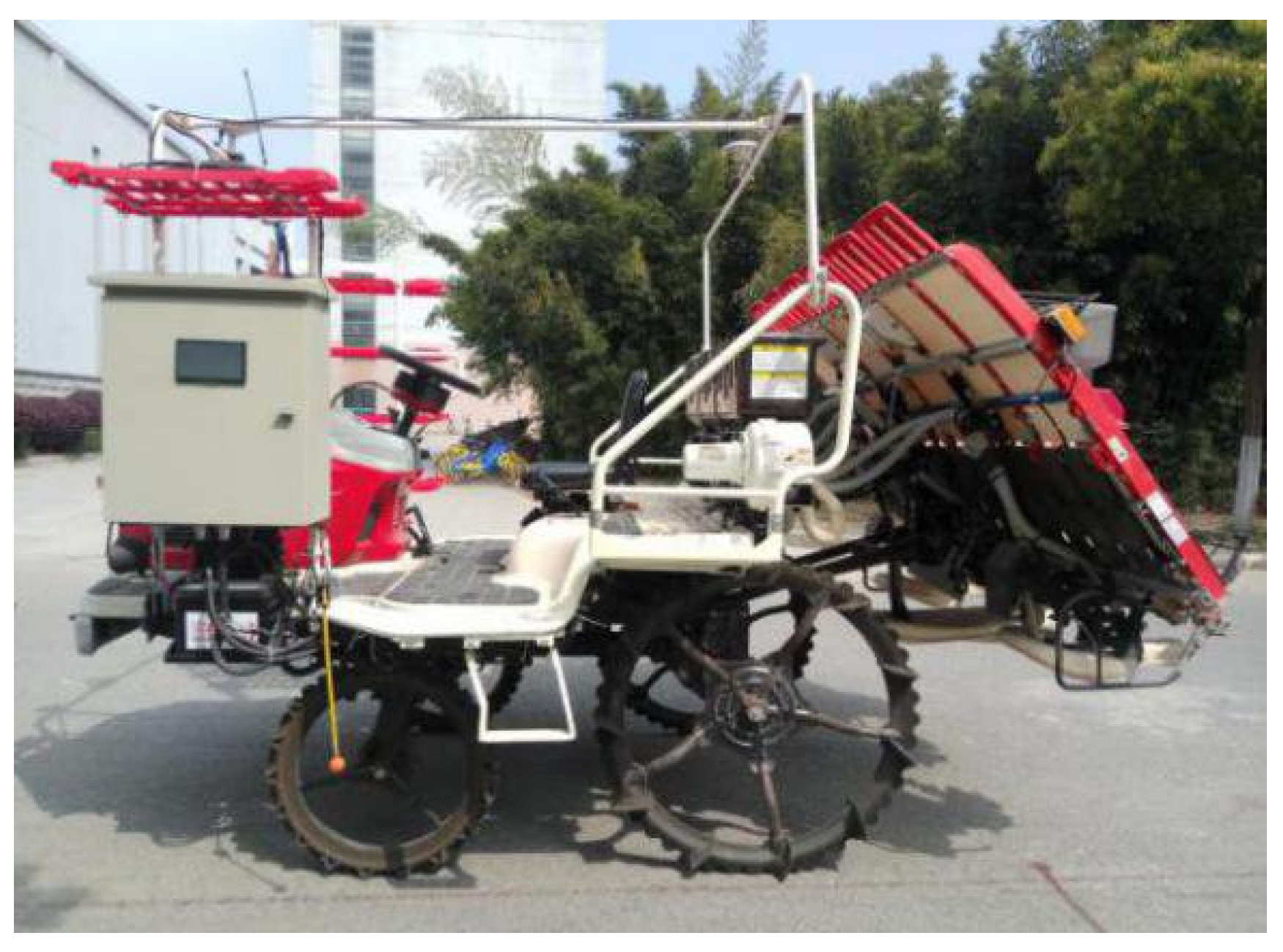
A six-row autonomous rice transplanter (2ZG-6DM, Nantong Fulaiwei Agricultural Equipment Co., Ltd., Nantong, China), as shown in Figure 2, was used as the experimental platform.
The proper visual distance and view angle are the premises for collecting high-quality seedling images. Therefore, the image acquisition platform of the seedling box needs to be adjustable in the height and shooting angle, and the platform should have a good stability.
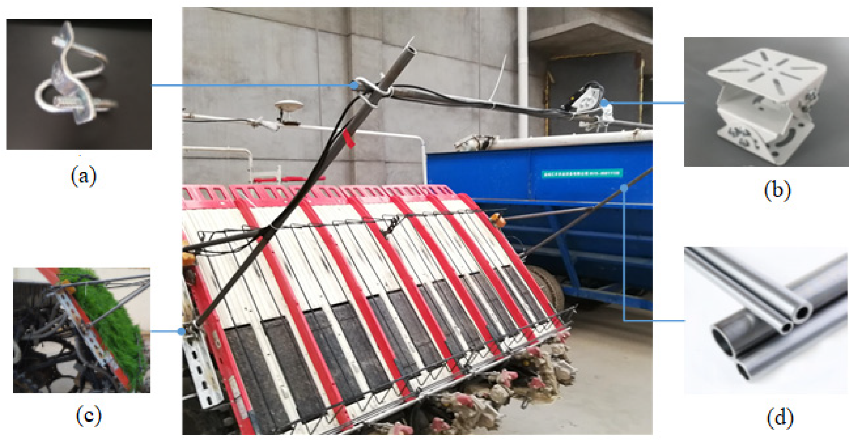
A set of a 3D universal joints from the perspective of practicality and cost-saving was chosen to realize the adjustable angle of the camera. If the platform is too high and too heavy, it will increase the shaking amplitude of the seedling box due to inertia when the seedling box moves horizontally. To meet the requirements of strength and lightness, some seamless steel pipes with a diameter of 20 mm are used. At the bottom of the platform, the triangular principle is used for the reinforcement to improve the overall stability of the platform. Figure 3 shows the structure diagram designed by Solid Works software. The designed image acquisition platform and components are shown in Figure 4.
The camera determines whether the whole monitoring system can meet the working requirements. To improve the diagnosis and calculation accuracy of the proposed monitoring system, it is necessary for a high-resolution camera. However, the high image resolution means a longer image processing time, which is not conducive to the real-time performance of the system. By compromising the real-time performance and resolution, the combination of the high-speed camera (GE200GC-T, Suzhou Mingo Automation Technology Co., Ltd., Suzhou, China) and lens (FA0401-5MP, Guangzhou Long Walk Photoelectric Technology Co., Ltd., Guangzhou, China) is determined. The main performance parameters of the camera and lens FA0401-5MP are shown in Table 2.

3. Camera Calibration

The concavity of the camera lens will distort the image information. To reduce the distortion degree of the image and improve the detection accuracy of the system, it is necessary to calibrate the camera. To obtain the three-dimensional spatial relationship between an object and its image, it is necessary to establish a camera model to solve the camera parameters. The whole process of obtaining camera parameters is called camera calibration.

3.1. Development of Camera Model

The imaging process of the camera is the conversion of the relation between the four reference coordinate systems. The four coordinate systems are the world coordinate system X w , Y w , Z w , which can take any point as the origin, the camera coordinate system X c , Y c , Z c , which takes the optical center of the camera as the origin, the image coordinate system u v o 0 , which takes the upper left corner of the image as the origin, and the pixel coordinate system x y o .

3.1.1. Conversion of Pixel Coordinate System to Image Coordinate System

An image cartesian coordinate system, as shown in Figure 5, was established, where u and v represent the rows and columns of the image, respectively. Pick any point p x , y in the coordinate system. d x and d y represent the true size of a pixel on a photosensitive chip. The relation between the pixel coordinate and the real size of the image can be described as
u = x d x + u 0 v = y d y + v 0
Equation (1) can be rewritten as:
u v 1 = 1 d x 0   u 0 0   1 d y   v 0 0     0     1 x y 1

3.1.2. Conversion from Camera Coordinate System to Image Coordinate System

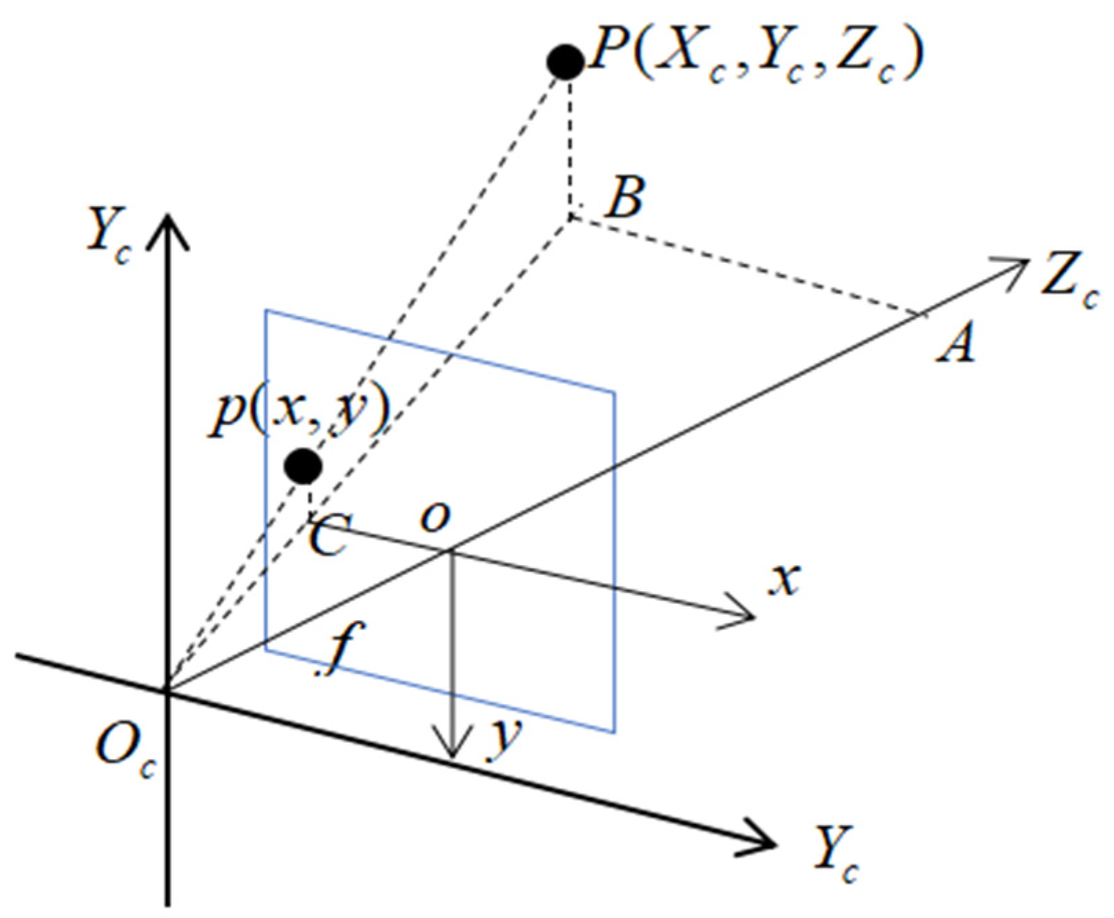
A coordinate system X c , Y c , Z c is established with the origin of the photocenter coordinate of the camera (Figure 6). Axis X c and Y c are parallel to axis x and y , respectively, and axis z is the optical axis of the camera. f is the focal length of the camera, which is determined by the internal parameters of the camera. It can be seen from Figure 6 that Δ A B O c ~ Δ o C O c and Δ P B O c ~ Δ p C O c ; therefore, the following expression can be obtained.
A B o C = A O c o O c = P B p C = X c x = Z c f = Y c y x = f X c Z c y = f Y c Z c
The corresponding matrix expression can be written as:
Z c x y 1 = f 0 0 0 0 f 0 0 0 0 1 0   X c Y c Z c 1

3.1.3. Conversion from World Coordinate System to Camera Coordinate System

The conversion from the world coordinate system to the camera coordinate system can be achieved using a rotation matrix R and a translation vector t . In homogeneous coordinates, the rotation matrix R can be transformed into a rotation vector of three independent variables by Rodrigues transformation. R is a 3 × 3 orthogonal identity matrix, and t is the translation vector of the camera with respect to the world coordinate system. Therefore, the rigid body transformation can be represented by three rotation vectors and three translation vectors with a total of six parameters, which are also known as the camera’s external parameters.
The relationship between the world coordinate system and camera coordinate system is described as:
X c Y c Z c 1 = R t 0 1   X w Y w Z w 1
The matrix expression of Equations (2), (4), and (5) can be summarized as:
Z c u v 1 = 1 d x 0 u 0 0   1 d y   v 0 0     0     1   f 0 0 0 0 f 0 0 0 0 1 0   R t 0 1   X w Y w Z w 1 = f x 0 c x 0 0 f y c y 0 0 0     1     0   R t 0 T 1   X w Y w Z w 1
where f x and f y are the scaling factors of axles u and v , respectively. c x , c y is the optical center.

3.1.4. Lens Distortion

Camera lens distortion mainly includes radial distortion along the radius direction of the lens and tangential distortion due to the non-parallelism between the lens and the camera sensor plane or image plane.
The mathematical model of radial and tangential distortions can be written as:
x = x 1 + k 1 r 2 + k 2 r 4 + k 3 r 6 + x + 2 p 1 x y + p 2 r 2 + 2 x 2 y = y 1 + k 1 r 2 + k 2 r 4 + k 3 r 6 + y + 2 p 1 x y + p 2 r 2 + 2 y 2
where x , y is the coordinate of the distortion point; k 1 ,   k 2 , and k 3 are the radial distortion coefficients; and p 1 and p 2 are the tangential distortion parameters.

3.1.5. Camera Calibration Method

Compared with other calibration methods, Zhang’s calibration method [35] has the advantages of simplicity and a high calibration accuracy, which has been widely used in the field of camera calibration in recent years. Therefore, this calibration method is applied in this study.
Zhang’s calibration method [35] takes the calibration plate as the plane of the spatial coordinate system X w O w Y w . The rotation matrix R is represented using the rotation vector and Z w is set as 0. The relationship between the world coordinate system and the pixel coordinate system is as follows [35]:
Z c u v 1 = K r 1 r 2 r 3 t   X w Y w Z w 1 = K r 1 r 2 t   X w Y w 1
where K is the internal parameter matrix and r 1   r 2   t is the rotation and translation matrix, denoted as:
H = λ K r 1 r 2 t = h 1 h 2 h 3
where λ is the scaling factor of H and the homography matrix.
Because r 1 is orthogonal to r 2 , the constraint conditions can be concluded as:
h 1 K T K 1 h 2 = 0 h 1 T K T K 1 h 1 = h 2 K T K 1 h 2
According to the above formula, the internal parameters of the camera can be deduced as follows:
f = d x λ / b 1 c x = b 3 f 2 / λ k 2 c y = b 2 b 3 b 1 b 6 / b 1 b 5 b 2 2 λ = b 9 b 3 2 + c y b 2 b 3 b 1 b 6 / b 1
b 1 b 2 b 3 b 4 b 5 b 6 b 7 b 8 b 9 = K T K 1
The external parameter matrix, which is achieved by solving the internal parameter matrix, can be written as:
r 1 = λ K 1 h 1 r 2 = λ K 1 h 2 r 3 = r 1 × r 2 t = λ K 1 h 3

4. Image Processing

4.1. Image Calibration

The checkerboard grid with the size of 28.5 mm × 28.5 mm, which is black and white and evenly distributed, was used to calibrate the camera. The checkerboard grid (Figure 7) was printed on A4 paper and laid flat on a stool. The ten pieces of images were selected by adjusting the angle and distance between the stool and the printed checkerboard grid.
The camera calibrator of Matlab 2017b is applied to calibrate the camera. The principle used is Zhang’s calibration method [35] and the calibration results are shown in Table 3.

4.2. Image Preprocessing

The image quality of the seedlings directly determines the detection accuracy of the whole monitoring system, and the feature information is the key to accurately identifying the seedlings. The color feature information of the seedlings is different from that of the background. Therefore, this paper conducts relevant research based on the color feature of the seedlings. In this paper, the image processing equipment is a personal PC, and the image processing software is Matlab 2017b.

4.2.1. Grey Scale Processing

The component method and weighted average method are the several grayscale methods widely used at present. The images of each seedling row in the seedling box collected in this paper are color images with a resolution of 1280 × 1024, which are superimposed by three channels R/G/B. The expressions of the component method and the weighted average method can be described by Equations (14) and (15), respectively.
g x , y = m a x { R x , y , G x , y , B x , y }
g x , y = a R x , y + b G x , y + c B x , y
where R x , y , G x , y , and B x , y are the red, green, and blue color component, respectively. a , b , and c are the weighed coefficients.
The fifteen images were randomly selected from the collected images, and the average values of the R/G/B components in the images f x , y were calculated.
f i , j R a = 75.95 G a = 90.79 B a = 48.88
Obviously, the G component is the largest and R is the second largest. The gray-scale effect is enhanced by adjusting the weight of the R/G/B component trial and error. The expression of the grayscale image of the seedlings in the seedling box can be written as:
g x , y = 0                                                             ( G < R   or   G < B ) 2 G 1.2 R 0.5 B                           others
Figure 8 shows the grayscale comparison of the G component method and the weighted average method.
The unmanned rice transplanter, which belongs to outdoor operation machinery, needs to work under a natural light source for a long time. The image quality is easily affected by the intensity change in outdoor light, which interferes with the subsequent image processing. Aiming at the problem that farmland image acquisition is easy to be affected by natural light, a combined strategy feature gray method was proposed [36], which has a strong adaptability to outdoor uneven lighting. The gray-scale effect is enhanced by adjusting the weight of the strategy combination. The expression of the combined strategy feature gray method can be written as:
R = R R m a x G = G G m a x B = B B m a x r = R R + G + B g = G R + G + B b = B R + G + B
E x G = 2 g r b
E x R = 1.4 r g
C I V E = 0.441 r 0.811 g + 0.385 b + 18.78745
V E G = g r a b 1 a ,   a = 0.667
Compared with entropy, uniformity is easier to calculate. Therefore, uniformity is chosen as the detection method in this study. The uniformity is expressed as:
U = i = 0 L 1 P 2 z i
where U denotes the uniformity; z i is the random variable of the grayscale level; P z i represents the histogram; and L is the number of different gray levels.
The uniformity U G k of each image can be written as:
U G k = 1 U G k G h Ω U G h
where Ω = G k | k E x G , E x G R , C I V E , V E G , w G k is a combination strategy coefficient.
w G k = U G k G h Ω U G h
G = Ω w G k G k
The effective combination strategy is obtained by acquiring image uniformity:
g i , j = 0.32 E x G + 0.29 C I V E + 0.09 V E G + 0.3 E x G R
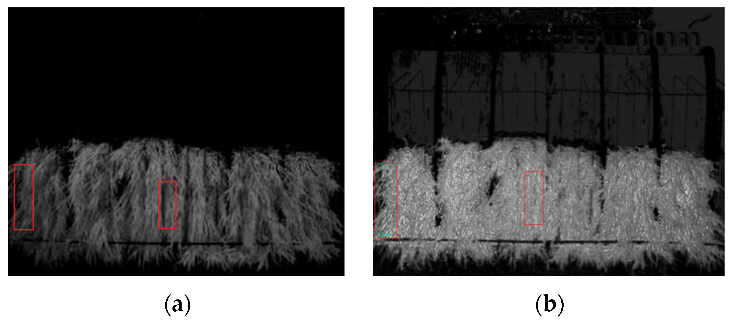
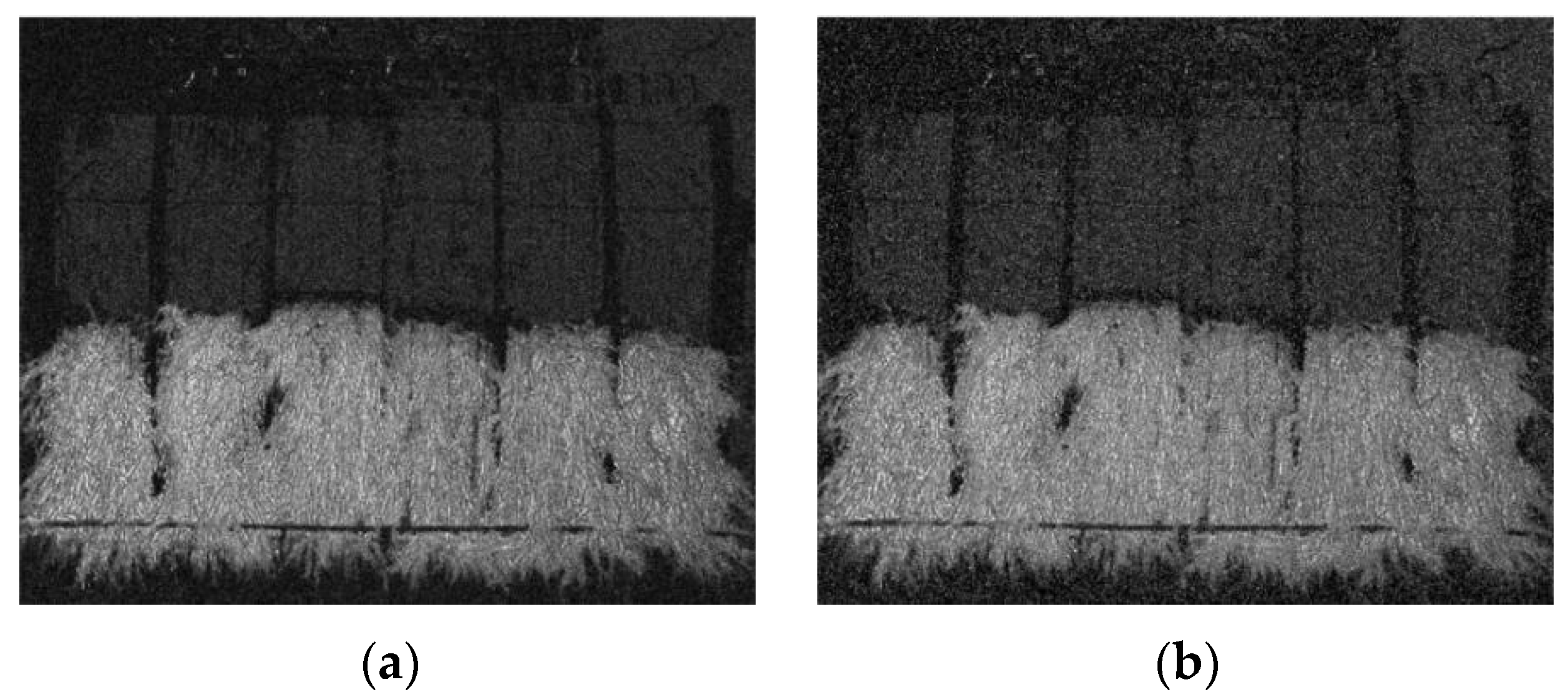
The effect comparison for two kinds of grayscale methods is shown in Figure 9.
It was found that the combination strategy feature gray method was better than the ultra-green feature gray method at the edge of the seedlings and in dark light conditions. Therefore, the combination strategy feature gray method is selected to the grayscale image.

4.2.2. Image Enhancement

The outdoor image information collected not only includes the color information of the seedling in the seedling box but also the interference noise caused by various factors such as mechanical jitter, electromagnetic equipment, and the transmission process, which will affect the subsequent processing of the image. Therefore, it is necessary to suppress the noise.
To analyze and compare the adaptability of different filtering methods to the farmland environment, various noise models were added to verify the filtering effect. Gaussian noise and salt and pepper noise, which are common in farmland environments, are analyzed in this study.
The filter processing requirements of the monitoring system of an unmanned rice transplanter in the farmland environment are a high real-time performance and keeping the image as clear as possible. To obtain an effective filter method, the comparison of mean filtering, median filtering, and adaptive median filtering is conducted. The comparison results are as shown in Table 4 and Figure 10, Figure 11 and Figure 12.
The effect and time of several filtering methods are comprehensively compared. The adaptive median filtering process relies on a constant comparison and iteration update, so the whole processing process is longer than the mean filtering and median filtering, which does not meet the real-time requirement. In summary, median filtering is selected in this paper.

4.2.3. Background Segmentation

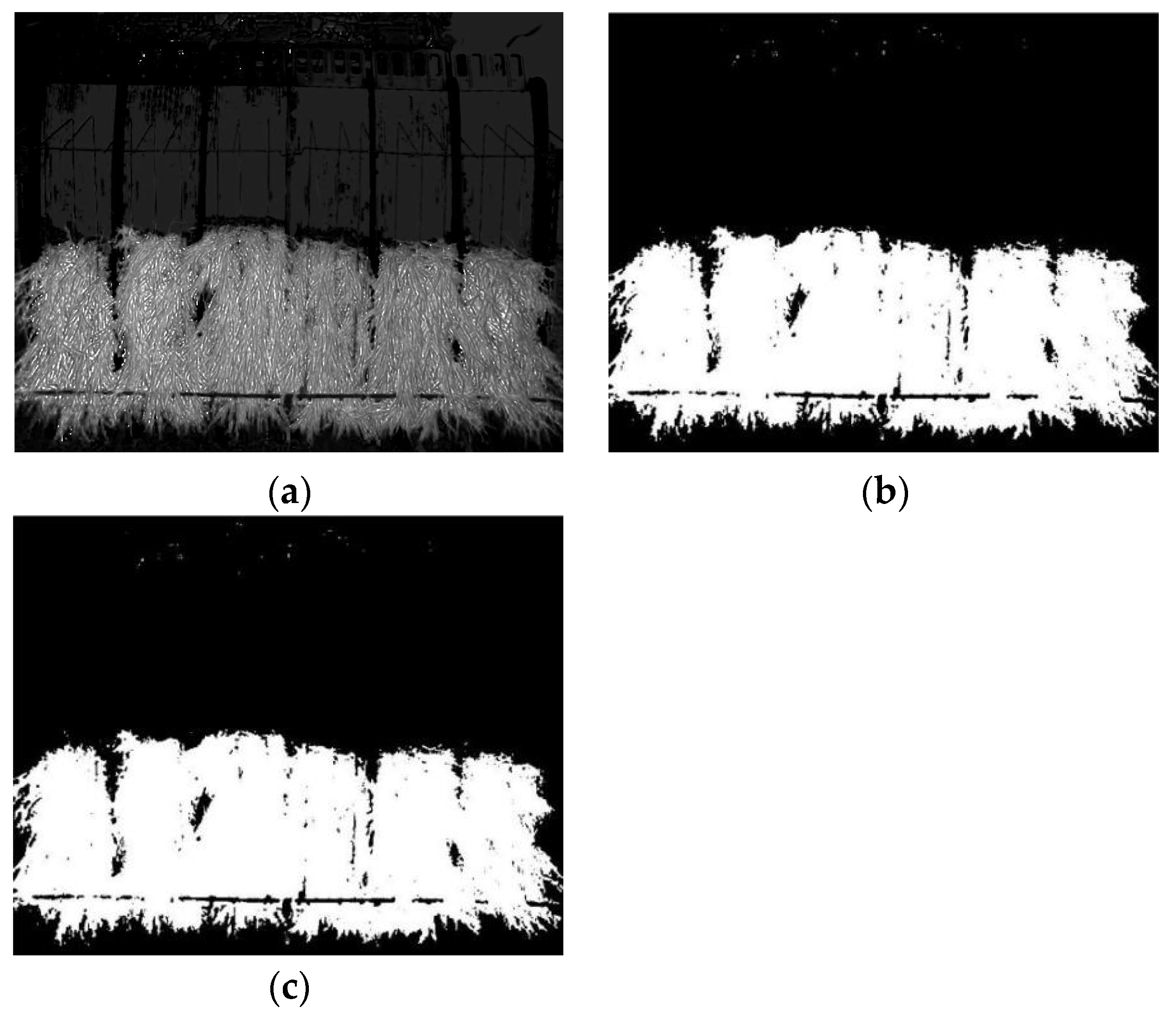
Background separation is actually to classify the pixel gray level of the image and then binarize it by setting a threshold to achieve the separation of the target and the background area. For the seedling in the seedling box, the difference between the target area seedling and the background seedling box is obvious, which can separate the seedling region from the background through the threshold segmentation. The iterative selection threshold (IST) method and Otsu algorithm are used, and the segment results as shown in Figure 13 are compared.
The optimum segmentation threshold and average computing time for the IST method are 70.96 and 0.086 s, respectively. However, the corresponding parameters for the Ostu algorithm are 69.74 and 0.007 s, respectively. Although the thresholds obtained by the two segmentation methods are similar, the processing time of the Ostu algorithm is shorter, which is more conducive to the real-time implementation of the system. Hence, the Ostu algorithm is selected in this study.

4.3. Segmentation Algorithm of Rice Seedling Row

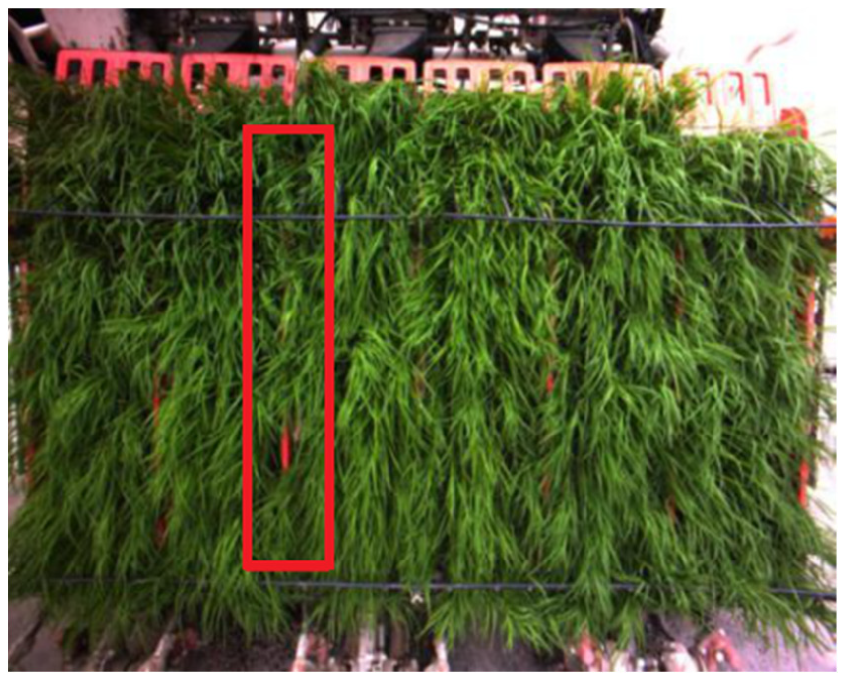
Through the above image processing process, the target seedlings were successfully separated as a whole from the seedling box background. However, the height of the seedlings is greater than that of the partition of the lattice of the seedling box. That is to say, the seedlings in the seedling box shield the partition of the lattice (Figure 14). This causes a problem that the seedling amount in each seedling lattice cannot be obtained directly. Therefore, for the convenience of the subsequent separation diagnosis of the seedling pieces and calculation of the remaining seedling amount, it is necessary to separate the seedlings into six rows so that the seedling in each lattice is separated into individual blocks.

4.3.1. Motion Region Segmentation Algorithm Based on Background Subtraction Method

The image acquisition platform is installed above the seedling box. During the transplanting operation of the transplanter, the rice seedling box moves transversely so that the transplanting mechanism can pick the seedling in the seedling box. The image acquisition platform and seedling box are relatively static in the same direction so that the image background information remains unchanged. Thus, we can separate the moving object from the background by using the background subtraction method.
The background subtraction method establishes a suitable background model based on the characteristic of the monitoring object such as a static background or simple movement [37]. Through image matching, all the information containing the background model is removed from the current frame image, and the remaining information is classified into different regions through judgment. Thus, the moving object and the background can be separated. The detailed expression of the background subtraction method can be described as:
I B t x , y = I t x , y B t x , y
R t x , y = 1 I B t x , y > T 1 0 e l s e
where I t x , y , B t x , y , and I B t x , y are the image of the current frame, background image, and background differential image, respectively. The values 1 and 0 denote the moving region and background zone, respectively.
Establishing a suitable background model is the key and difficult problem of the background subtraction method algorithm. The adaptive hybrid Gaussian model [38] provides a reliable idea for model development, which regards the values of the pixels in a video sequence as a time series X 1 , X 2 , . . . . ,   X T 2 = I x , y , t : 1 t T 2 and expresses the features of the pixel point x , y by multiple independent Gaussian distributions. The pixels are then matched with the mixed Gaussian model. The pixel point is the background point when X t μ , t 1 2.5 σ k , t 1 , otherwise it is the foreground point. The weights and mean variances of the new images are used to update the parameters of the Gaussian model.
In this study, the image after preprocessing only remains the target region, which reduces the complexity of the interframe image changes. For each pixel, 3~5 Gaussian models are usually required. However, the seedling is simply described as 1 ,   s e e d l i n g   r e g i o n ;   0 ,   b a c k g r o n d   r e g i o n by binarization because only the color characteristics of the seedlings were retained in this study. The seedling region of each row, which is considered a background model, is obtained based on the baffle of the seedling box. The background model can be expressed as:
g f x , y = 1 g t e m p x , y g e x , y = 0 0 g t e m p x , y g e x , y = 1
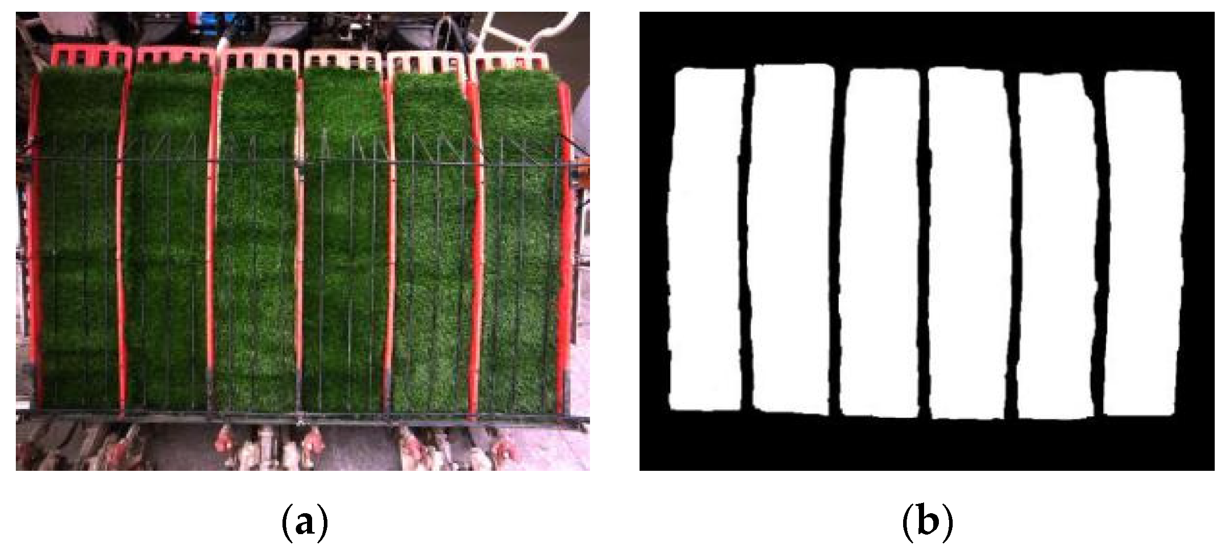
where g f x , y , g e x , y , and g t e m p x , y are the remaining seedling region of each row, the preprocessed image of the current frame, and the background image model, respectively. When the pixel points of the background model are the same as that of the current frame, it means that the current pixel points are the seedling areas. When the pixel difference between the background model and the current frame is 1, it implies that the area is the background area. A lawn was used to cover the seedling area on the seedling box, and the processed image was used as the background model (Figure 15). The raw seedling image and the segment results obtained by the background subtraction algorithm are shown in Figure 16.

4.3.2. Image Morphological Processing

From the segmented renderings, as shown in Figure 16b, there are some narrow cracks in the seedling image of each area and the shielding of the pressing seedling rod. Therefore, it is necessary to perform morphological processing on these slits and the occlusions to restore the image information. The morphological processing of images mainly includes corrosion, expansion, open and close operation, and cavity filling. Expansion: for the sets S 1 and S 2 of the elements on Z 2 , use S 1 to expand S 2 , denoted as S 2 S 1 , so the detailed expression can be described as:
S 2 S 1 = z | ( S ) z S 2 ϕ
Corrosion: for the element sets S 1 and S 2 of Z 2 , use S 1 to corrode S 2 , denoted as S 2 S 1 , so the detailed expression can be written as:
S 2 S 1 = z | ( S ) z S 2
The expansion was applied to Figure 16b to connect the occlusion areas and the slit region, and then corrosion was used to smooth the edges of the areas. The result was as shown in Figure 17. The narrow cracks in the seedling image of each area were effectively eliminated by using the morphological processing method.

4.4. Image Analysis

4.4.1. Diagnosis of Separation of Seedling Pieces

After the above treatment, the whole seedling region of the seedling box has been completely separated from the background and the individual seedling rows can be seen. The seedlings in the seedling box presents three kinds of states such as the fault, normal, and missing row (Figure 18). The missing row can also be regarded as a special case of the fault state. The leakage transplanting area will be generated if the fault of the seedling pieces (Figure 18a) cannot be found in time.
Through the analysis of the three states, it is found that, under the normal state, the seedlings in the seedling box form a complete region in terms of the units of the row. Based on this phenomenon, the status of each row seedling was monitored by marking the centroid position of each zone. When a fault occurs, two or more areas appear in a row. If the distance between the mass centers of the upper and lower regions is increasing, which implies that the seedling fault state is worsening, the operator must be reminded to eliminate the fault. Otherwise, when the distance between the center of the mass of the upper and lower regions decreases, it indicates that the fault state is weakening and can continue to be observed. When the center of the mass in the lower region is 10 cm away from the bottom of the seedling box, it is necessary to remind the operators to eliminate it if the fault still does not disappear. Based on the above analysis, the flowchart (Figure 19) was designed for fault diagnosis.

4.4.2. Calculation of Seedling Residual Amount in Seedling Box

For the six-row rice transplanters, the seedling box can be regarded as six rows separated by partitions. The remaining number of seedlings in each row determines the operating distance of the rice transplanter. The distance to be planted is related to the seedling area of each row in the seedling box.
Based on the minimization idea, each area is regarded as a square with an area of ξ . However, the image has a resolution limit and the minimum unit area is the pixel size, thus the area of each zone can be expressed as:
ξ = d x × d y
The seedling area of each row can be written as:
S i = i = 1 l i ξ i
where S i is the seedling area of each row and l i is the pixel number of each row seedling.
Supposing S m is the seedling area of each row when the seedling box is full, then the proportion of the real-time surplus of each row can be expressed as:
L i = S i S m × 100 %
During the transplanting of the rice transplanter, the seedling amount consumed for planting a row is related to plant spacing, the number of seedlings per grab, and the working distance. The relationship can be written as:
d s = S D q i × d × λ .
L s = S D S m × 100 % .
where S D , d s , and d are the consumption amount of seedlings for one-way working, the length of the operating row, and the spacing of the seedlings, respectively, and q , λ , and L s are the amount of seedlings taken by the planting claw at one time, the transplanting coefficient, and the consumption ratio of single-way transplanting seedlings, respectively.
The transplanting efficiency is:
L s d s = q S m × d × λ
The distance can be planted of the remaining seedlings amount in each row, and d i can be expressed as:
d i = S i S m ÷ L s d s = L i × S m × d × λ q

4.5. Design of Monitoring Software

4.5.1. Function Analysis of Software

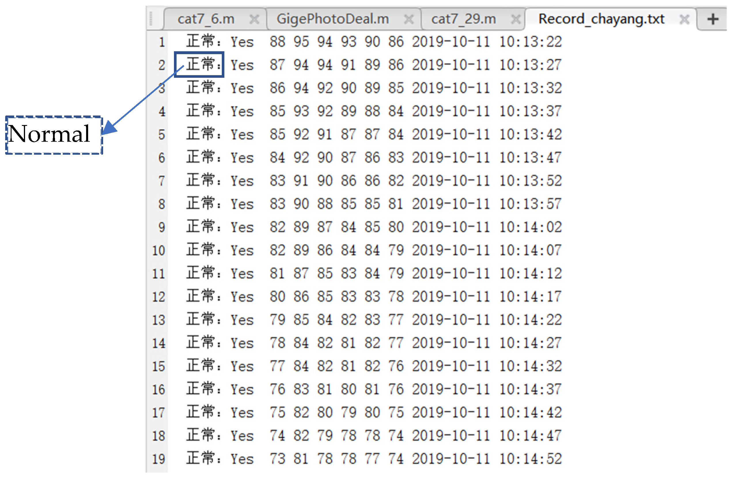
The monitoring process of the seedling fault and seedling remaining amount based on the machine vision is shown in Figure 20. First, the seedling box image is acquired and directly transmitted to the PC through the Vision Gige interface. The acquired image is displayed on the PC monitoring interface to complete the system calibration. The calibration parameters of the camera in Table 3 are used to calibrate the system. Second, the fault state and the information on the seedling remaining amount are obtained by the processing and analysis of the image. Then, the image information is sent to the vehicle control unit through the USB_232 serial port for data fusion, and the result is presented. Finally, the raw image, the image after correction, the image after being processed, and the key information of the image (seedling status and seedling remaining amount information) are displayed in the monitoring interface. Moreover, the key information of the image was saved as a .txt document for the convenience of the subsequent system stability analysis. Meanwhile, the seedling information of the seedling box is sent to the vehicle control unit (STM32ZET6) through the serial port.

4.5.2. Image Development Tools and Environment

The image processing algorithm programs in this paper are implemented based on the Matlab platform, and the system monitoring interface is designed and written using the GUI tool in Matlab R2017b software.

4.5.3. Design of Software Data Processing Process

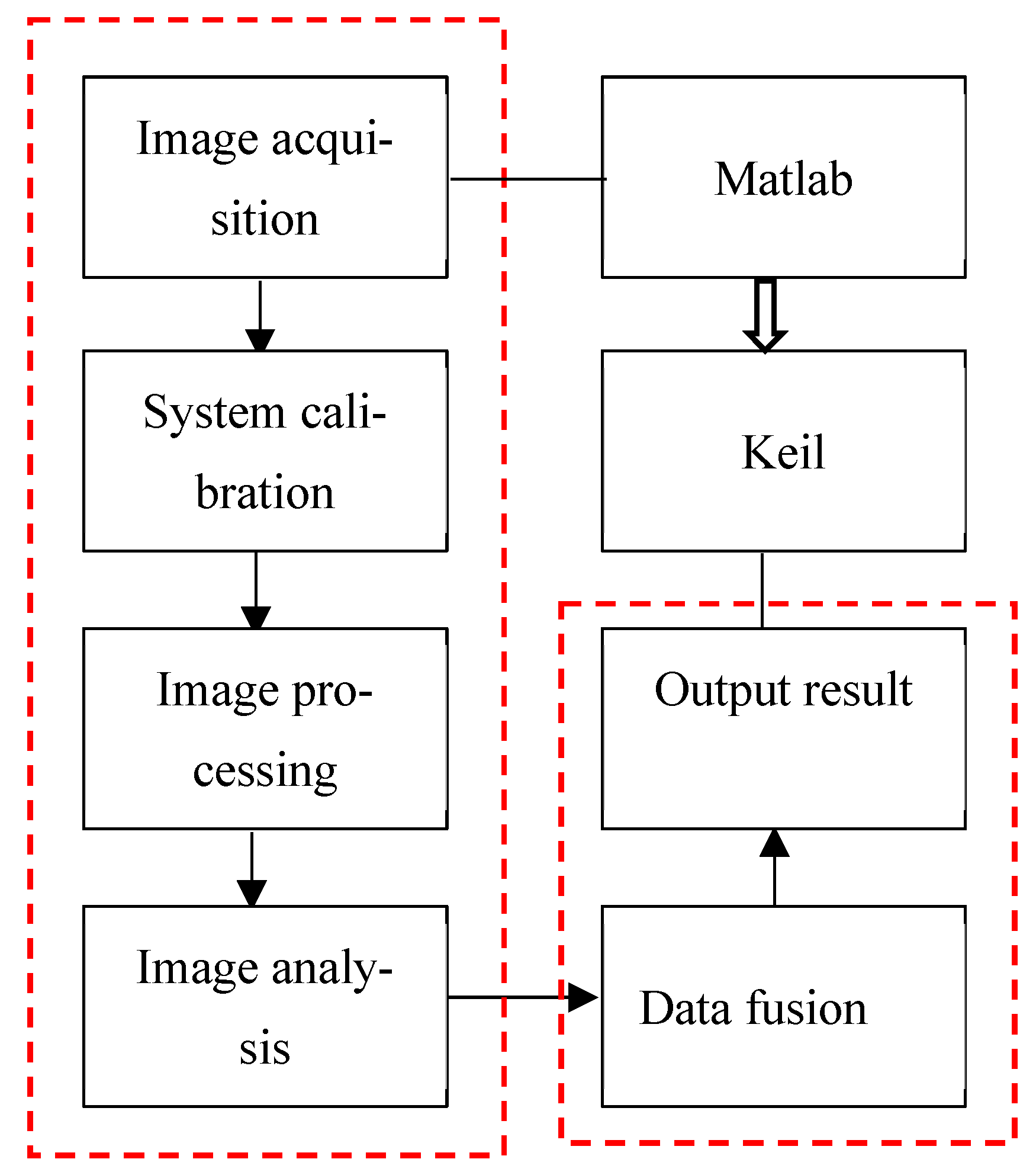
According to software function analysis, the whole fault diagnosis of the seedling pieces and seedling remaining amount monitoring can be divided into two parts. One part is based on Matlab software for system calibration, image acquisition, processing, and analysis. The other is the data fusion and the output of the processing results based on Keil software, as shown in Figure 21.
First, the system is calibrated by using Zhang’s calibration method [35]. After setting the camera’s acquisition parameters, as shown in Table 3, and configuring the camera driver, the seedling images are acquired. Then, to obtain real-time seedling regional information of each row of the seedling box, the collected seedling images are processed by a series of algorithms such as distortion correction, combined strategy grayscale, median filtering, Otsu threshold segmentation, background subtraction method seedling row segmentation, and morphological processing.
Based on the processed images, the fault diagnosis of the seedling pieces and the calculation remaining seedling amount are conducted for each row of seedlings. Then, the image information is converted into digital information for the convenience of the subsequent data fusion.
The vehicle control unit receives the navigation data and the processed seedling image data. The planting distance of the remaining seedling quantity in the seedling box is calculated by calculating the seedling transplanting efficiency.
When the seedling fault occurs, the transplanter stops to travel, and the alarm signal generates. Otherwise, the transplanter will continue to operate if the available seedlings in the seedling box are enough for transplanting to the supplying seedling site in the field. Moreover, when the transplanter travels across the supplying seedling site, if the available seedlings in the seedling box are not enough for transplanting back to the supplying seedling site next time, it will stop to travel and the alarms. The rice transplanter resumes transplanting until the seedling box is fully reloaded and the alarm automatically eliminates.

5. Field Test and Data Analysis

To validate the effectiveness of the proposed monitoring system, the paddy field tests are carried out in the grain industrial park of XINGHUA City, JIANGSU Province.
A 100 m × 30 m rectangular field was selected for the experiment. The unevenness of the paddy soil was less than 5 cm. The mud foot depth in the area is about 25 cm. During the paddy field experiments, the vehicle track with a depth of about 25 cm was generated after the vehicle traveled across the planned paths.
The four longitude and latitude coordinates of the field vertices were collected by the navigation module and transformed into the current field coordinates. According to the operating width of the rice transplanter, the field operation path was independently planned and autonomously generated.

5.1. Performance Test for the Seedling Amount

Before the experiments, the parameters such as the height and view angle of the camera, the spacing of the seedlings, and the number of seedlings taken by the planting claw at one time were previously set. Twelve pieces of conventional mat-type seedlings are carefully loaded into the seedling box. Once the transplanter starts to travel along previously planned paths, the proposed monitoring system starts to work. First, the tests of the seedling amount are conducted. During the experiments, the seedling amount of each row in the seeding box is manually measured with tape from the top of the seedling. To ensure data synchronization from the manual measurement and the monitoring system, the transplanting operation of the autonomous transplanter is stopped during the manual measurement. For each sample, the measurement data with three replications are obtained by manual measurement (real value) and the proposed monitoring system (measurement value). Then, the data with three replications are averaged and the ratio of the current seedling amount of each row to the seedling amount of the full row is calculated. The real value and the measurement value for each row are compared. Table 5 shows the results of the fourth row. Due to space constraints, the measurements of other rows are not provided.
Moreover, the seedling information was saved to the specified path. Txt document to facilitate the subsequent analysis. The experiment results are shown in Figure 22, Figure 23 and Figure 24. The monitoring interface, as shown in Figure 22, mainly displays the original image, corrected image, and processed image as well as the seedling information such as the seedling state in the seedling box and real-time surplus of each seedling row. The seedling information was saved to the specified path. txt document (Figure 23). Figure 24 shows that the navigation controller can receive and display the seedling amount of each row in real-time.
Table 5 shows that the relative error between the real value and the measurement value is below 3%, which implies that the proposed monitoring system achieves enough accuracy.

5.2. Performance Test for Seedling Fault

To verify the diagnosis ability for the seedling fault, the fault of the seedling in each row was artificially set by wrinkling the seedling pieces, which makes the seedling pieces hunch. It is found that the alarm device immediately alarms once the seedling pieces are in a state of fault. The results of many tests indicate that the accuracy of diagnosis is 100%. This signifies that the system has a strong ability to the diagnosis of the seedling fault.

5.3. Performance Test of the Plantable Distance of the Seedling

To examine whether the proposed monitoring system can predict the planting distance based on the number of seedlings in the seedling box, several run field experiments are conducted. The autonomous rice transplanter travels along the previously planned paths. The alarm device of the lack of seedlings is observed when the rice transplanter approaches the seedling storage place in the field. It is found that the alarm device almas when the seedling in the seedling box is insufficient for transplanting the round trips (about 180 m). Meanwhile, the plantable distance of the seedling can be observed from the monitoring interface. This implies that the good performance of the system in terms of predicting the planting distance based on the number of seedlings in the seedling box is achieved.

5.4. Real-Time Test of the System

To investigate the real-time performance of the system, 20 seedling images were analyzed, and the processing time is shown in Table 6.
Table 6 shows that the image processing time is less than 1.5 s. Based on the velocity of the transplanter and agronomy requirements, the system has a good real-time performance.

6. Conclusions

The current autonomous transplanter needs to carry at least one person for loading the seedling. For this problem, a real-time monitoring system of the seedling fault and seedling amount in the seedling box was presented based on the seedling image information. We focused on the practical operation situation, performed the research on the monitoring system of the seedling fault and seedling amount based on machine vision, and conducted experiments and analyses to verify the effectiveness of the developed monitoring system. Through the above research work and experiments, the following conclusion can be drawn:
(1)
Based on the actual operation requirements, the image acquisition platform of the seedlings was developed, which moved as the seedling box moved. Because the seedling box and the platform are relatively stationary, our designed platform can easily acquire a high-quality image and avoid applying the complex image processing method.
(2)
By the information fusion of navigation data and the remaining seedling amount in the seedling box, the distance can be planted based on the remaining seedlings amount in each row that can be obtained in real-time. According to this distance, the person supplying the seedlings can decide whether there is a need to reload seedlings into the seedling box or not when the rice transplanter travels across the seedling site in the field.
(3)
The seedlings in the seedling box shield the partition of the lattice. To this problem, the combination of the background subtraction method and image morphological processing was used to segment the seedling image, which could separate the region of interest from the background. Thus, the individual region of each row was obtained to facilitate the calculation of the remaining seedling amount and the fault diagnosis of each row.
(4)
The combination of the median filter and Otsu method was determined by comparing it with other filter methods and background separation methods. Our proposed method has a good real-time performance and robustness.
(5)
The experimental results show that the image processing time is less than 1.5 s and the relative error of the seedling amount is below 3%, which indicates that the designed monitoring system can accurately realize the fault diagnosis of the seedling pieces and monitor the remaining amount of each row.
Some limitations in this study still need to be overcome. For example, this study was limited to supplying the seedlings when the rice transplanter passed through the place of the seedling storage situated at the headland. In the future, we decide to conduct a study on the path planning of the breakpoint endurance so that the rice transplanter can automatically return to the supplying seedling place when the seedling amount in the seedling box is not enough. The rice transplanters can go back to the breakpoint and continue to operate when the supplying seedling finishes.

Author Contributions

Conceptualization, J.L. and M.Z.; methodology, D.G.; software, M.Z.; validation, J.L.; formal analysis, G.Z.; investigation, J.L.; resources, J.L.; data curation, M.Z.; writing—original draft preparation, G.Z.; writing—review and editing, M.L.; visualization, M.L.; supervision, J.L.; project administration, J.L. All authors have read and agreed to the published version of the manuscript.

Funding

This research was funded by the Key Research and Development Program of Zhenjiang city (NY2022008), and the Key Research and Development Program of Jiangsu Province (BE2018324).

Institutional Review Board Statement

Not applicable.

Informed Consent Statement

Not applicable.

Data Availability Statement

No new data were created or analyzed in this study. Data sharing is not applicable to this article.

Conflicts of Interest

The authors declare no conflict of interest.

References

  1. Zhou, J.; He, Y.Q. Research progress on navigation path planning of agricultural machinery. Trans. CSAM 2021, 52, 1–14. (In Chinese) [Google Scholar]
  2. Yoshisada, N.; Hidefumi, S.; Katsuhiko, T.; Masahiro, S.; Kyo, K.; Ken, T. An autonomous rice transplanter guided by global positioning system and inertial measurement unit. J. Field Robot. 2009, 26, 537–548. [Google Scholar]
  3. Yin, X.; Du, J.; Noguchi, N.; Yang, T.X.; Jin, C.Q. Development of autonomous navigation system for rice transplanter. Int. J. Agric. Biol. Eng. 2018, 11, 89–94. [Google Scholar] [CrossRef]
  4. Lohan, S.K.; Narang, M.K.; Singh, M.; Singh, D.; Sidhu, H.S.; Singh, S.; Dixit, A.K.; Karkee, M. Design and development of remote-control system for two-wheel paddy transplanter. J. Field Robot. 2021, 39, 177–187. [Google Scholar] [CrossRef]
  5. Li, J.Y.; Shang, Z.J.; Li, R.F.; Cui, B.B. Adaptive sliding mode path tracking control of unmanned rice transplanter. Agriculture 2022, 12, 1225. [Google Scholar] [CrossRef]
  6. Nagasaka, Y.; Umeda, N.; Kanetai, Y.; Taniwaki, K.; Sasaki, Y. Autonomous guidance for rice transplanting using global positioning and gyroscopes. Comput. Electron. Agric. 2004, 43, 223–234. [Google Scholar] [CrossRef]
  7. Nagasaka, Y.; Kitagawa, H.; Mizushima, A.; Noguchi, N.; Saito, H.; Kobayashi, K. Unmanned rice-transplanting operation using a GPS-Guided rice transplanter with long mat-type hydroponic seedlings. Agric. Eng. Int. CIGR Ejournal 2007, 9, 1–10. [Google Scholar]
  8. Kohei, T.; Akio, O.; Motomu, K.; Hiroyuki, N.; Manabu, N.; Tatsumi, K. Development and field test of rice transplanters for long mat type hydroponic rice seedlings. J. JSAM 1997, 59, 87–98. [Google Scholar]
  9. Li, Y.X.; He, Z.Z.; Li, X.C.; Ding, Y.F.; Li, G.H.; Liu, Z.H.; Tang, S.; Wang, S.H. Quality and field growth characteristics of hydroponically grown long-mat seedlings. Agron. J. 2016, 108, 1581–1591. [Google Scholar] [CrossRef]
  10. John Deere. Available online: https://www.deere.com/en/technology-products/precision-ag-technology/data-management/operations-center/ (accessed on 19 March 2022).
  11. Trimble. Available online: https://agriculture.trimble.com/product/farmer-core/ (accessed on 12 February 2022).
  12. CLAAS. Available online: https://www.claas.cn/products/claas/easy-2018/connectedmachines (accessed on 18 June 2018).
  13. Zhang, F.; Zhang, W.; Luo, X.; Zhang, Z.; Lu, Y.; Wang, B. Developing an IoT-Enabled cloud management platform for agricultural machinery equipped with automatic navigation systems. Agriculture 2022, 12, 310. [Google Scholar] [CrossRef]
  14. Cao, R.Y.; Li, S.C.; Wei, S.; Ji, Y.H.; Zhang, M.; Li, H. Remote monitoring platform for multi-machine cooperation based on Web-GIS. Trans. CSAM 2017, 48, 52–57. [Google Scholar]
  15. Lan, Y.B.; Zhao, D.N.; Zhang, Y.F.; Zhu, J.K. Exploration and development prospect of eco-unmanned farm modes. Trans. CSAE 2021, 37, 312–327. [Google Scholar]
  16. LianShi Navigation. Available online: https://allynav.cn/nongyejiance (accessed on 24 March 2022).
  17. Wang, A.C.; Zhang, W.; Wei, X.H. A review on weed detection using ground-based machine vision and image processing techniques. Comput. Electron. Agric. 2019, 158, 226–240. [Google Scholar] [CrossRef]
  18. Pantazi, X.E.; Moshou, D.; Tamouridou, A.A. Automated leaf disease detection in different crop species through image features analysis and One Class Classifiers. Comput. Electron. Agric. 2019, 156, 96–104. [Google Scholar] [CrossRef]
  19. Picon, A.; Alvarez-Gila, A.; Seitz, M.; Ortiz-Barredo, A.; Echazarra, J.; Johannes, A. Deep convolutional neural networks for mobile capture device-based crop disease classification in the wild. Comput. Electron. Agric. 2019, 161, 280–290. [Google Scholar] [CrossRef]
  20. Qiu, Z.J.; Zhao, N.; Zhou, L.; Wang, M.C.; Yang, L.L.; Fang, H.; He, Y.; Liu, Y.F. Vision-based moving obstacle detection and tracking in paddy field using improved Yolov3 and deep SORT. Sensors 2020, 20, 4082. [Google Scholar] [CrossRef] [PubMed]
  21. Montalvo, M.; Pajares, G.; Guerrero, J.M.; Romeo, J.; Guijarro, M.; Ribeiro, A.; Ruz, J.J.; Cruz, J.M. Automatic detection of crop rows in maize fields with high weeds pressure. Expert Syst. Appl. 2012, 39, 11189–11897. [Google Scholar] [CrossRef]
  22. Rovira-Mas, F.; Zhang, Q.; Reid, J.F.; Will, J.D. Hough-transform-based vision algorithm for crop row detection of an automated agricultural vehicle. Proc. Inst. Mech. Eng. Part D J. Automob. Eng. 2005, 219, 999–1010. [Google Scholar] [CrossRef]
  23. Dionisio, A.; Angela, R.; César, F.Q.; José, D. Using depth cameras to extract structural parameters to assess the growth state and yield of cauliflower crops. Comput. Electron. Agric. 2016, 122, 67–73. [Google Scholar]
  24. Jean, F.I.N.; Umezuruike, L.O. Machine learning applications to non-destructive defect detection in horticultural products. Biosyst. Eng. 2020, 189, 60–83. [Google Scholar]
  25. Lim, J.H.; Choi, K.H.; Cho, J.; Lee, H.K. Integration of GPS and monocular vision for land vehicle navigation in urban area. Int. J. Automot. Technol. 2017, 18, 345–356. [Google Scholar] [CrossRef]
  26. Zhang, Q.; Chen, M.E.S.J.; Li, B. A visual navigation algorithm for paddy field weeding robot based on image understanding. Comput. Electron. Agri. 2017, 143, 66–78. [Google Scholar] [CrossRef]
  27. Chen, X.Y.; Wang, S.A.; Zhang, B.Q.; Luo, L. Multi-feature fusion tree trunk detection and orchard mobile robot localization using camera/ultrasonic sensors. Comput. Electron. Agric. 2018, 147, 91–108. [Google Scholar] [CrossRef]
  28. Opiyo, S.; Okinda, C.; Zhou, J.; Mwangi, E.; Makange, N. Medial axis-based machine-vision system for orchard robot navigation. Comput. Electron. Agric. 2021, 185, 106153–106164. [Google Scholar] [CrossRef]
  29. Liu, F.C.; Yang, Y.; Zeng, Y.M.; Liu, Z.Y. Bending diagnosis of rice seedling lines and guidance line extraction of automatic weeding equipment in paddy field. Mech. Syst. Signal Process. 2020, 142, 106791. [Google Scholar] [CrossRef]
  30. Yutaka, K.; Kenji, I. Dual-spectral camera system for paddy rice seedling row detection. Comput. Electron. Agric. 2008, 63, 49–56. [Google Scholar]
  31. José, M.G.; José, J.R.; Gonzalo, P. Crop rows and weeds detection in maize fields applying a computer vision system based on geometry. Comput. Electron. Agric. 2017, 142, 461–472. [Google Scholar]
  32. Wang, S.S.; Zhang, W.Y.; Wang, X.S.; Yu, S.S. Recognition of rice seedling rows based on row vector grid classification. Comput. Electron. Agric. 2021, 190, 106454. [Google Scholar] [CrossRef]
  33. Ma, Z.H.; Yin, C.; Du, X.Q.; Zhao, L.J.; Lin, L.P.; Zhang, G.F.; Wu, C.Y. Rice row tracking control of crawler tractor based on the satellite and visual integrated navigation. Comput. Electron. Agric. 2022, 197, 106935. [Google Scholar] [CrossRef]
  34. Zhang, Q.; Wang, J.H.; Li, B. A method for extracting the centerline of seedling column based on YOLOv3 object detection. Trans. Chin. Soc. Agr. Mach. 2020, 51, 34–43. [Google Scholar]
  35. Zhang, Z.R. A flexible new technique for camera calibration. IEEE Trans. Pattern Anal. Mach. Intell. 2000, 22, 1330–1334. [Google Scholar] [CrossRef] [Green Version]
  36. Guijarro, M.; Pajares, G.; Riomoros, I.; Herrera, P.J.; Burgos-Artizzu, X.P.; Ribeiro, A. Automatic segmentation of relevant textures in agricultural images. Comput. Electron. Agric. 2011, 75, 75–83. [Google Scholar] [CrossRef] [Green Version]
  37. Mei, N.N.; Wang, Z.J. Moving object detection algorithm based on Gaussian mixture model. CED 2012, 33, 3149–3153. [Google Scholar]
  38. Stauffer, C.; Grimson, W. Adaptive background mixture models for real-time tracking. In Proceedings of the IEEE Conference on Computer Vision and Pattern Recognition, Fort Collins, CO, USA, 23–25 June 1999. [Google Scholar]
Figure 1. Long-mat seedling and the modified seedling box.
Agriculture 13 00371 g001
Figure 2. Experimental platform of autonomous rice transplanter.
Agriculture 13 00371 g002
Figure 3. Solid Works chart of image acquisition platform.
Agriculture 13 00371 g003
Figure 4. Image acquisition platform and components. (a) Double U cross hoop buckle; (b) three-dimensional universal joint; (c) triangular fixing bracket; (d) seamless steel tube.
Agriculture 13 00371 g004
Figure 5. Conversion of pixel coordinate system to image coordinate system.
Agriculture 13 00371 g005
Figure 6. Camera coordinate system conversion image coordinate system.
Agriculture 13 00371 g006
Figure 7. Checkerboard for calibration.
Agriculture 13 00371 g007
Figure 8. Grayscale comparison of the G component method and weighted average method. (a) Original image; (b) G component method; (c) weighted average method.
Agriculture 13 00371 g008
Figure 9. Effect comparison for two kinds of grayscale methods. (a) Super green features; (b) combination strategy.
Agriculture 13 00371 g009
Figure 10. Filtering effect of mean filtering on Gaussian noise and salt and pepper noise. (a) Gaussian noise; (b) salt and pepper noise.
Agriculture 13 00371 g010
Figure 11. Filtering effect of median filtering on Gaussian noise and salt and pepper noise. (a) Gaussian noise; (b) salt and pepper noise.
Agriculture 13 00371 g011
Figure 12. Filtering effect of adaptive median filtering on Gaussian noise and salt and pepper noise. (a) Gaussian noise; (b) salt and pepper noise.
Agriculture 13 00371 g012
Figure 13. Comparison of segmentation effect for Ostu algorithm and iterative selection threshold method. (a) Image before segmentation; (b) segmentation effect of iterative selection threshold method; (c) Ostu algorithm.
Agriculture 13 00371 g013
Figure 14. Seedling sheltering.
Agriculture 13 00371 g014
Figure 15. Reference image acquisition. (a) Raw seedlings of lawn; (b) segment result.
Agriculture 13 00371 g015
Figure 16. Raw seedling image and the segment result. (a) Raw seedlings; (b) segment result.
Agriculture 13 00371 g016
Figure 17. Segment results by morphological processing.
Agriculture 13 00371 g017
Figure 18. Three kinds of different states of the seedling. (a) Fault state; (b) normal state; (c) lack row state.
Agriculture 13 00371 g018
Figure 19. Flow chart of fault diagnosis.
Agriculture 13 00371 g019
Figure 20. Software flow chart.
Agriculture 13 00371 g020
Figure 21. Data processing flow of seedling box monitoring system.
Agriculture 13 00371 g021
Figure 22. Monitoring interface.
Agriculture 13 00371 g022
Figure 23. Information storage.
Agriculture 13 00371 g023
Figure 24. The control terminal of the vehicle control unit.
Agriculture 13 00371 g024
Table 1. Comparison of main literatures.
MethodsSource ImageApplicationsResults or AccuracyReferences
Row vector grid classificationColor imagesRecognition of rice seedling rows89.22%[32]
System geometryRGB imagesCrop rows and weeds detection in maize fieldsMaximum deviation for path following: 7.7 cm for crops with height 14 cm[31]
Standardization
thresholding
AND operation
NIR images
Red images
Rice seedling row detectionIt can successfully detect the seedling rows under cloudy conditions [30]
Deep learning-based methodVideo streamBending diagnosis of rice seedling lines and
guidance line extraction
/[29]
Gabor filter
PCA
K-means clustering algorithm
Raw color imageOrchard robot navigationRMSE for the lateral deviation was 45.3 cm; maximum trajectory tracking error: 14.6 mm; SD: 6.8 mm.[28]
Yolov3 and deep SORTRGB imagesMoving obstacle detection/[20]
Multi-feature fusionRGB imagesTree trunk detection and orchard mobile robot localizationAverage localization error: 62 mm; recall rate: 92.14%;
Accuracy: 95.49%.
[27]
Table 2. Main performance parameters of camera GE200GC-T and lens FA0401-5MP.
TypeParameters
Camera dimension (mm)29 × 29 × 40
Size of the target area1/1.8″
Pixel size (μm)4.5 × 4.5
Shutter modeGlobal shutter
Effective pixel2 million pixels (600 × 1200)
Resolution @ frame rate1600 × 1200@60 fps/1280 × 1024@70 fps/800 × 600@118 fps
Data interfaceRJ45
Trigger modeContinuous/soft/hard trigger
Exposure control (ms)0.016~91
Data formatMono8p;RGB8p;YUV422p; BayerRG8/10p, BayerGB8/10p;
power supply mode (V)DC 12
Compatible target area1/1.8″
Len interfaceC-Mount
Focus length (mm)6
Focusing range (mm)100~
Lens size (mm) φ 38.2 × 27.9
Table 3. Calibration results of the camera.
ParametersOutput Results
Internal parameter matrix[763.1827 0 0; −0.3839 814.2960 0; 631.7540 445.5892 1]
Radial distortion k 1 = −0.0957, k 2 = 0.2147, k 3 = −0.1740
Tangential distortion p 1 = −0.0100, p 2 = 0.0025
Mean error of pixel0.2430
Table 4. Comparison of filtering methods.
Filtering MethodGaussian Noise (s)Salt and Pepper Noise (s)Enhancement Effect
Mean filtering0.0220.062poor
Median filtering0.1480.101good
Adaptive median filtering1.5381.271optimal
Table 5. Real value and the measurement value of the seedling amount.
Real Value (%)Measurement Value (%)Relative Error (%)
13.7212.89−2.54
24.5925.132.15
35.8636.612.05
46.7847.080.64
53.6352.98−1.22
62.6961.77−1.49
71.2173.282.82
80.9679.65−1.64
88.7689.010.28
96.5695.89−0.70
Table 6. Image processing time of 20 seedling images.
No.Time (s)No.Time (s)
11.455876111.387314
21.321593121.399905
31.314241131.176554
41.297413141.400023
51.421732151.441549
61.384999161.335629
71.405213171.364401
81.438917181.365961
91.401312191.396413
101.404978201.401021
Disclaimer/Publisher’s Note: The statements, opinions and data contained in all publications are solely those of the individual author(s) and contributor(s) and not of MDPI and/or the editor(s). MDPI and/or the editor(s) disclaim responsibility for any injury to people or property resulting from any ideas, methods, instructions or products referred to in the content.