Article

Comparison of Crushing Effect of Differently Shaped Crushing Rollers on Whole-Plant Silage Maize

1
College of Agriculture and Food Engineering, Shandong University of Technology, Zibo 255049, China
2
College of Mechanical and Electronic Engineering, Northwest A&F University, Xianyang 712100, China
*
Author to whom correspondence should be addressed.
Agriculture 2023, 13(7), 1276; https://doi.org/10.3390/agriculture13071276
Submission received: 24 May 2023 / Revised: 15 June 2023 / Accepted: 16 June 2023 / Published: 21 June 2023
(This article belongs to the Section Agricultural Technology)

Abstract

:
Based on the mechanical test (shear test, compression test), the bond model of corn kernel and straw was established to explore the rolling and crushing effect of different crushing rollers. The type of crushing roller is different. The material crushing process by the force (extrusion and kneading) is different. The mechanical analysis of the crushing process reveals that the disc crushing roller (DCR) has the characteristics of large unit-length kneading area; the spiral-notched serrated crushing roller (SNSCR) has transverse shearing effect on the material; and they affect the crushing effect of the material. By means of discrete element method and simulation test, multiple regression method and variance analysis method are used to systematically analyze the data. The optimal working parameters of each roll (crushing roll speed, crushing clearance, differential ratio) were obtained. The simulation test and bench test of the crushing process of materials with different roll shapes were carried out under the optimal working parameters. The crushing effect was evaluated with a Binzhou screen and a corn silage grain-crushing score screen. The crushed materials of corn kernel can be divided into three categories according to the size (broken grains passed through 2 mm sieve; broken grains passed through 4.75 mm sieve; and broken grains that cannot pass through 4.75 mm sieve), and the crushed materials of corn stalk can be divided into four categories according to the size and thickness (broken straw through 4 mm sieve; broken straw through 8 mm sieve; broken straw through 19 mm sieve; and broken straw that cannot pass 19 mm sieve). The crushing effect and crushing classification of the simulation test and bench test were basically consistent. The results showed that the disc crushing roller group had the highest comprehensive score with straw rolling rate of 89.1% and grain crushing rate of 87.7%, which was the most suitable for harvesting whole-plant silage maize (WSM).

1. Introduction

Corn is one of the most commonly planted grains and feed in China. In 2020, the corn planting area of China reached 4.5 × 10⁷ hm2, ranking first worldwide. WSM has large raw material planting areas, low cost, rich nutrition, and good smell. It has the advantages of aroma, high digestibility, and long storage time. It is the preferred feed for ruminant livestock, such as cattle and sheep. Increasing WSM feed can also effectively alleviate the current shortage of animal husbandry feed [1,2].
Results from a published study indicated that cows fed diets containing processed corn silage harvested at three chop lengths (0.95, 1.45, and 1.90 cm) had increased dry matter intake, bodyweight, milk production, and milk fat concentration compared with cows fed diets containing unprocessed corn silage harvested at 0.95 cm [3]. Shredding can increase the digestibility of dry matter, organic matter, starch, crude fiber, and neutral detergent fiber in the body, thus increasing the production of milk or meat [4]. The increase in milk production for cows fed processed corn silage-based diets could be related to increased ruminal and total tract starch digestibility compared with cows fed unprocessed corn silage-based diets [3,5]. However, in the harvesting process of corn silage, different crushing roller types have different effects on the silking and crushing of silage, which will affect its subsequent fermentation and eventually the ingestion, digestion, and absorption of the feeding ruminants [6].
The prerequisite for silage production is crushing the whole plant of corn. Therefore, first, the mechanical properties of corn need to be analyzed. Chevanan Nehru et al. [7] designed, produced, and tested the shear strength and flow properties of corn stalks. The tests were performed at 3.80 kPa pressure and 5.02 kPa. Under the pressure, the normal stress significantly affected the displacement and friction coefficient values promoting shear failure. The displacement range caused by shear failure depends on the pressure, normal stress, and particle size. The internal friction angle, yield strength, main consolidation strength, and viscous strength of corn stalks have been measured. Kaliyan Nalladurai et al. [8] studied the compression characteristics of corn straw and established the constitutive model of corn straw.
Crushing roll is the key component to realizing material crushing [9,10]. Tian Fuyang et al. [11] designed a self-driven silage harvester; studied the cutting mode and parameters of crushing roll; and determined the optimal diameter, speed, and number of teeth of crushing roll, which can harvest silage corn, alfalfa, herb mulberry, and other crops. According to the mechanical test, the discrete element model of corn straw was established; the silage crushing and throwing device was developed; and the mechanical characteristics of corn straw crushing and throwing process were obtained by optimizing the feed rate, crushing speed, and scale speed by using the method of simulation and bench test [12]. Zhang Fengwei et al. [13] established a discrete element model of corn stalks based on mechanical tests and developed a hammer-type kneading machine. Using a combination of simulation and bench tests, the mechanical properties of the corn stalk kneading and crushing process were obtained. The crushing effects of corn stalks were classified into four categories: short, standard, long, and incomplete crushing. This research method can be used for reference to evaluate the crushing effect. The crushing effect of silage affects the feeding, digestion, and absorption of livestock. Drewry Jessica L et al. [2] found that completely crushed corn kernels not only reduce the energy consumption of the chewing of dairy cows but also improve the digestion and absorption of the cows. In comparison, whole corn kernels are difficult to digest and absorb by dairy cows. It is necessary to measure the qualified rate of broken grain, which is helpful to intuitively see the merits and demerits of feed quality.
The above studies only involve single crushing or mechanical determination tests of grains or straw; however, some crushing devices are backward and single. Moreover, there is a lack of systematic and relevant research on the crushing process, mechanical properties, and crushing effect of WSM. Conducting theoretical and experimental research on different types of corn silage kneading and crushing rollers as well as evaluating and comparing the final kneading and crushing effects are highly significant for improving the palatability of silage, promoting straw fermentation, and accelerating nutrient conversion. The purpose of this study is to conduct a theoretical analysis of the crushing processes of different crushing roller types. Specifically, combined with the DEM, mechanical characteristics tests of WSM are performed, and the bonded particle model (BPM) is established; simulation tests are conducted, and the different crushing roller types are compared. Through the discrete element method combined with the crushing test, the most suitable crushing roller for silage corn was selected. The crushing effects are compared by shape classification to solve the problems of low crushing rate and poor fermentation quality of corn silage feed [14].

2. Principle and Analysis

2.1. Structure and Principle of Silage Comprehensive Test Bench

The silage comprehensive test bench used in this study includes a precompression feeding device, chopping device, kneading and crushing device, throwing device, power transmission device, and console. The structure of the silage comprehensive test bench is shown in Figure 1. In the figure, 3 and 4 denote a pair of crushing rollers, which are the core working parts of the silage machine. The two rollers have the same structure, different speeds, and opposite rotations to produce a differential crushing effect, which realizes the differential extrusion and kneading of WSM as well as shearing and crushing, effectively improving the straw rubbing rate and the grain crushing rate.
During the operation of the silage comprehensive test bench, whole plants of corn enter the precompression feeding device through a feed inlet, and the stalks are grabbed and precompressed. The stalks are clamped by a floating feeding roller with decreasing gap and increasing speed. Straightening and conveying improve the consistency of the stalk posture and chopped length; furthermore, under the support of the feeding roller and a fixed knife, the whole plants of corn can be chopped to fixed lengths and divided into two pieces. In the kneading and crushing device composed of differential kneading and crushing rollers, the crushing gap is much smaller than the diameter of the chopped corn plants, and the action of the differential speed results in the squeezing, crushing, and kneading of the small corn pieces. The speed of the crushing roller is high and can overcome inertia. The crushed materials are thrown out of the machine by force, and finally, the whole plants of corn are crushed.

2.2. Different Types of Crushing Rolls

Different crushing rollers have different tooth profiles, i.e., under differential speed operation, the size, direction, and magnitude of the shearing force of the roller teeth are different during the material crushing process. This results in different principles of material crushing and, finally, different material crushing effects. Therefore, it is necessary to conduct mechanical analysis of the crushing processes of different crushing roller types.

2.2.1. Disc Crushing Roller

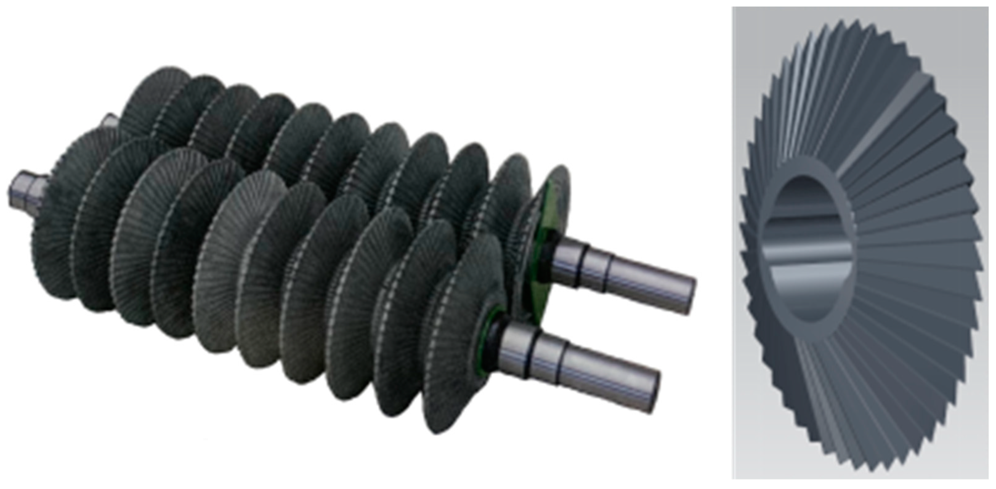
The number of discs depends on the width of the crushing unit, and they are made of 9SiCr, a highly reliable and wear-resistant alloy tool steel. Extremely few or extremely large number of disc teeth can affect the kneading and crushing effect of straw, and the best effect can be achieved with 48 disc teeth [12]. As shown in Figure 2, the crushing gap of DCR has a V-shaped structure, which is conducive to the grasping of materials. The disc cone angle, θ, is generally in the range of 35–45°, and the ratio of its unfolded area to that of conventional crushing rollers with the same width is 1 / sin θ 2 . Specifically, the kneading crushing area can be increased by 2.6–3.3 times for the same width, which can significantly improve the kneading crushing efficiency of materials.
The crushing of a material and the force on it during the operation of DCR are shown in Figure 3. In Figure 3a, as ω1 > ω2, the two discs rotate at a differential speed in opposite directions, and the differential speed ratio is between 15% and 35%. Therefore, a material is subjected to the upward force of both discs at any point P in the crushing gap. Taking the material at point P as an example, the linear velocities of the left and right crushing discs at this point are
{ v 1 = l 1 ω 1 v 2 = l 2 ω 2
Because ω1 > ω2 and l1 > l2, an effect of differential rubbing and crushing is achieved.
The force analysis of the material crushing process is shown in Figure 3b, which includes a clamping stage (A), complete crushing stage (B), and throwing stage (C). In the figure, l0 is the width of the crushing gap, and v1 and v2 are the linear velocities of the two disc cutters, respectively. The forces in each stage are
F 1 cos θ 1 F 2 cos θ 2 G 1 = m a 1
F r 1 cos θ 3 F r 2 cos θ 4 G 2 = m a 2
The whole crushing process includes clamping and squeezing followed by shearing and rubbing-crushing by the tooth-shaped edge. Specifically, WSM larger than the crushing gap is instantly rubbed and shredded or broken into small particles by the high-speed rotating crushing rollers and finally thrown out along the disc in the tangential direction. In the whole process, it is squeezed, cut, torn, and rubbed, leading to the shredding of the straw and the crushing of the seeds, improving the conditions for the subsequent fermentation of silage.

2.2.2. Conventional Serrated Crushing Roller (CSCR) and Spiral-Notched Serrated Crushing Roller

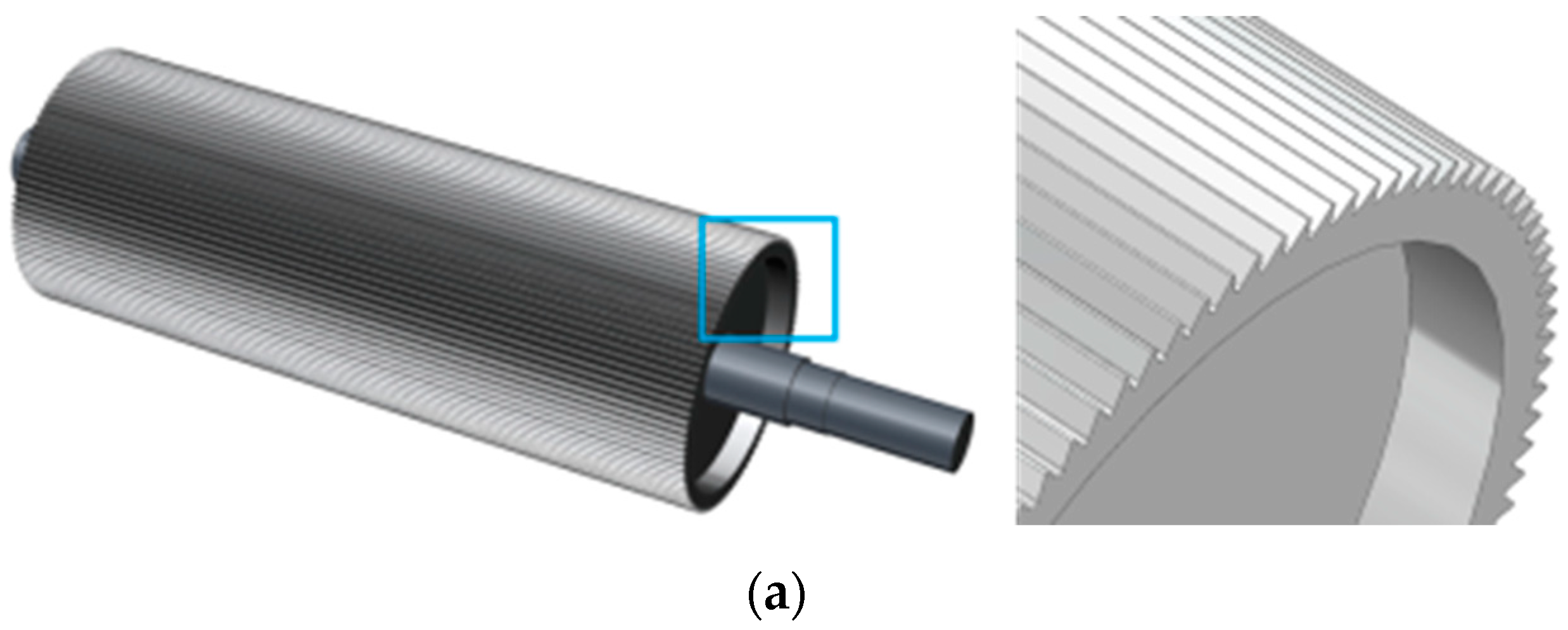
The teeth of two types of serrated crushing rollers are shown in Figure 4. A spiral-notched serrated crushing roller is based on the conventional tooth-type crushing roller with triangular notches in a spiral line distribution. This crushing roller can achieve a differential speed effect on the material rubbing and crushing and simultaneously apply a transverse shear of the material through the spiral distribution of the triangular notches, thereby improving the operational efficiency and the silking effect.
As shown in Figure 5a, the teeth of the roller have a sharp surface (a plane with a smaller angle from the normal direction than the opposite plane) and blunt surface (a plane with a greater angle from the normal direction than the opposite plane); the angle of inclination of the sharp surface is α, °; the angle of inclination of the tonal surface is β, °; the angle of the inner cone is ɤ = α + β + 360/n, °; n is the number of teeth; the width of the tooth tip is δ, mm; the radius of the tooth top circle is Ra, mm; the radius of the tooth root circle is Rb, mm; the tooth height is h = RbRa, mm; and τ is the tooth pitch, mm. As shown in Figure 5b, to ensure the kneading and crushing effect, triangular notch height s and triangular notch width l2 are generally taken as approximately 3 mm, and the ratio of single tooth width l3 to triangular notch width l4 is generally 2:1. The distance between the two rollers is ξ, mm; the total length of each roller is L, mm; the number of spiral coils is Q = L/(l3 + l4); and the inclination angle of the spiral line is φ [11,12,13].
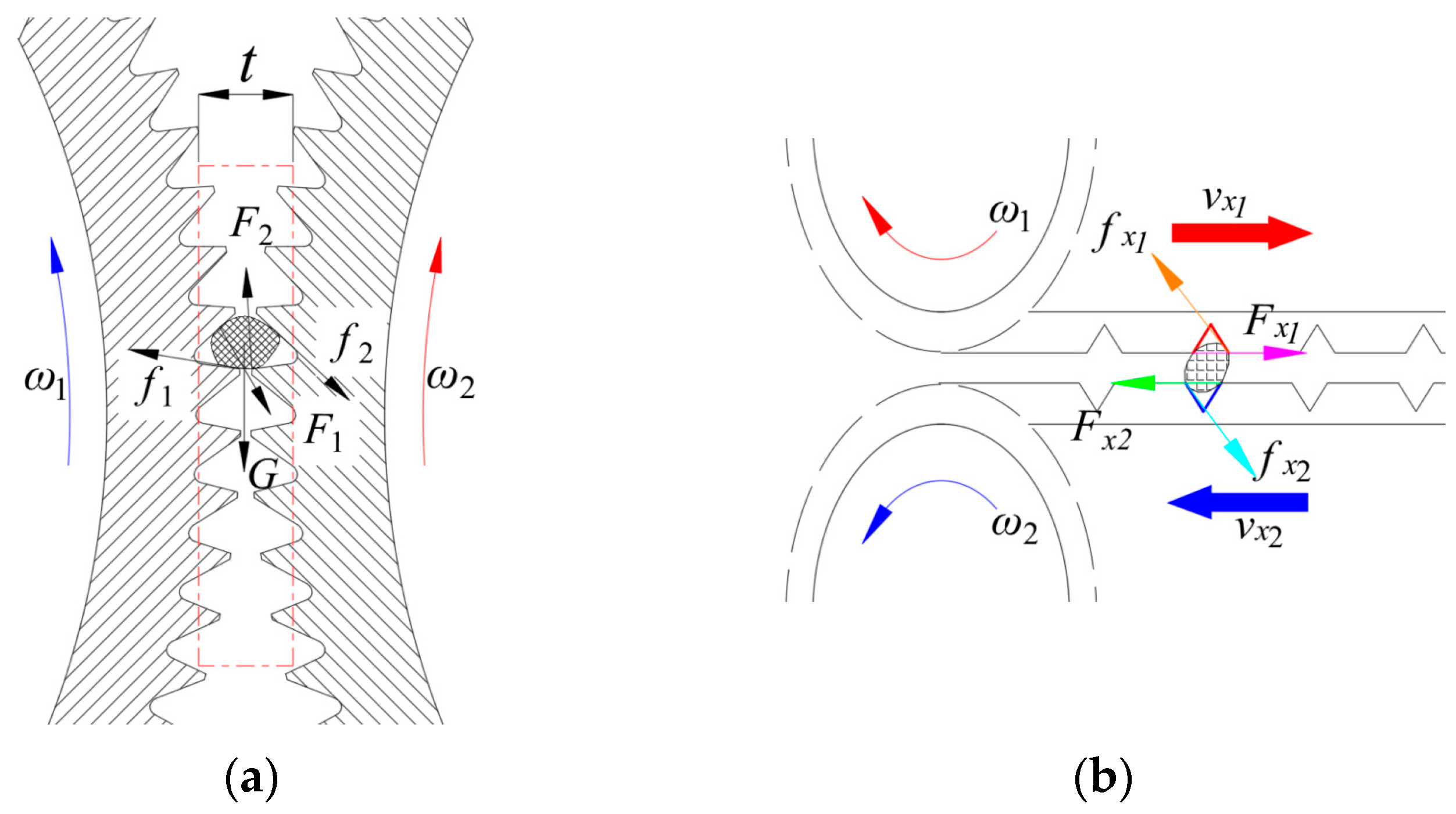
Because the roller teeth have a sharp and blunt face, the two crushing rollers form four types of cooperation: sharp face to sharp face, blunt face to sharp face, sharp face to blunt face, and blunt face to blunt face. In the front face to front face case, the shear role is strong but not conducive to stalk rubbing silk. In the blunt face to front face case, the fast roller crushing teeth blunt face is up, and the slow roller crushing teeth front face is down, which is suitable for processing hard and brittle materials. The blunt face to blunt face cooperation has the strongest extrusion and the weakest shear role among all types. The front face to blunt face cooperation can achieve extrusion and kneading accompanied by a shear effect, making it suitable for crushing tough materials such as corn straw. Its force analysis is shown in Figure 6a, where the speeds of the two rollers are ω1 and ω2, respectively, and ω1 > ω2; t is the effective crushing gap, mm; F1 and F2 are the roller teeth shear force, N; and f1 and f2 are the friction force of the teeth on the material, N. The horizontal crushing force analysis of the spiral-notched zigzag crushing roller is shown in Figure 6b. The upper notch moves to the right along the spiral, and the lower notch moves to the left along the spiral. The material is subjected to 5 forces in the longitudinal direction and 4 lateral forces at the same time. The two gaps meet to perform transverse shear to the material sandwiched in between, where Fx1 and Fx2 are the shear force of the roller tooth gap on the material, N; fx1 and fx2 are the friction force of the roller tooth gap on the material, N.
Compared with the other two cylindrical crushing rollers, the disc crushing roller has a V-shaped crushing gap, which greatly improves the operating efficiency and has a better crushing effect on silage corn grains with higher water content. With conventional sawtooth crushing roll as the control group, helical notched serrated crushing roll is improved on this basis, which not only achieves the effect of differential rubbing and crushing of the material but also completes the transverse shearing of the material with the triangular gap of spiral distribution, which can improve the working efficiency, especially increasing the number of rubbing for straw.

3. Discrete Element Simulation Modeling

The discrete element method (DEM) is an analytical method based on molecular dynamic principles for studying particle dispersion materials and their kinematic pattern of motion, which was first proposed in 1971 [15]. This can be used to simulate the deformation and crushing of discrete particle assemblies under quasi-static or dynamic conditions. The Hertz–Mindlin bonding model can be used to bond small particles to maize grain and maize stover models required for the test, whose kneading and crushing can be observed visually under the differential velocity of the crushing roller. This is convenient for data collection and recording and facilitates the experimental research and analysis of maize grain silage crushing and maize stover kneading [16].

3.1. Contact Model

Bonded particle model (BPM) was originally proposed by Potyondy and Cundall [17] to solve rock fragmentation problems. When two adjacent particles A and B are in contact or close to each other, and the distance between their spherical centers is less than the maximum bond radius, they will bond in parallel and form an intersection region at the contact location. Moreover, eventually the particles will bond as a whole. When the external force is greater than the interparticle bonding force, the bond will break, and the two particles will subsequently separate. The particle bonding model is shown in Figure 7.

3.2. Particle Model

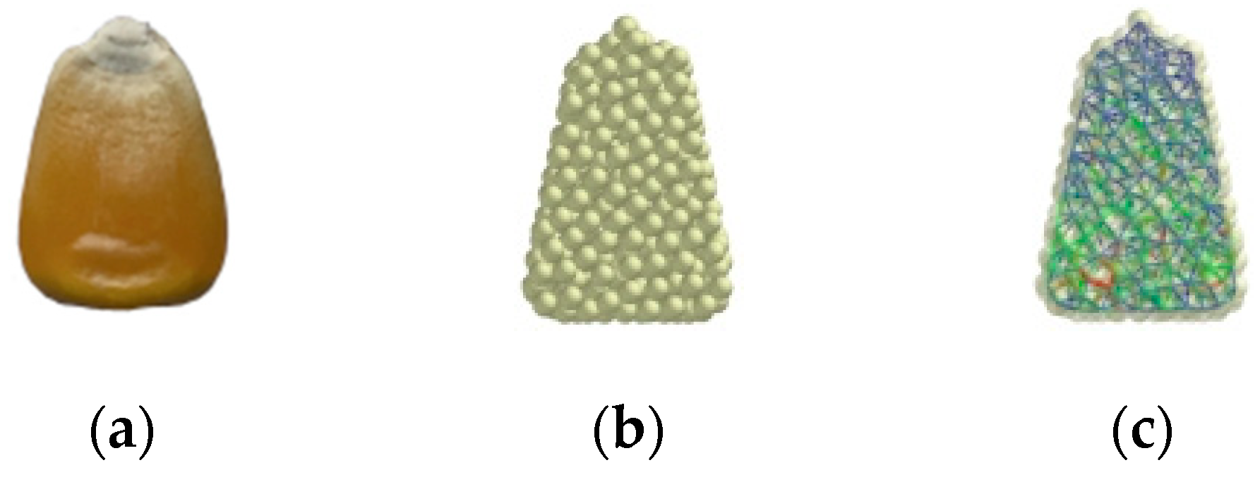
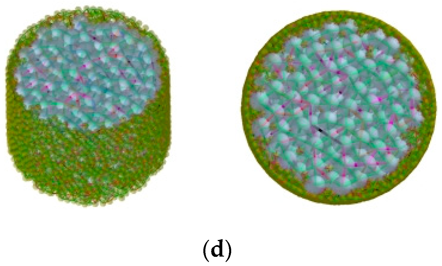
In this study, the maize variety used was Zhengdan 958 (Institute of Grain Crops, Henan Academy of Agricultural Sciences, Zhengzhou, China), which is commonly planted in northern China. One hundred kernels with full grains were randomly selected, and the dimensional parameters of the maize kernels (kernel length, upper kernel width, lower kernel width, and kernel thickness) were repeatedly measured using a vernier caliper and averaged. Among the kernels, one kernel with measurement closest to the average measurement was selected (Figure 8a). A three-dimensional model of the kernels drawn in UG10.0 based on the measured values was imported into the EDEM 2018 software, and small spheres with a radius of 0.52 mm were selected for filling. The BPM was generated based on the measured maize seed parameters, with each blob forming a whole by bonding (Figure 8c). One hundred maize stalks were randomly selected and cut into sections, similar to the cutting of the stalks into 3–5 cm sections by the cutting device before entering the crushing unit. The dimensional parameters of the small sections of the maize stalks were repeatedly measured using vernier calipers to obtain the average values. A three-dimensional model of the straw was drawn in UG10.0 based on the measured values, considering the biological structure of the straw itself. To improve the analysis of the kneading and crushing (if the filled particles are extremely large, the crushing effect is reduced) and the computer simulation time (if the filled particles are small, the simulation time is extremely long), the model was imported into the EDEM software. Owing to the high toughness and strength of the outer skin of straw and the thinner thickness, a radius of 0.52 mm was chosen. Because the inner core of straw is comparatively less ductile and strong, a ball of radius 1.30 mm was used to fill the outer skin of the straw, forming a discrete model of the straw. Specifically, each section of the straw was filled with 2038 balls of radius 0.52 mm and 525 balls of radius 1.30 mm, generating the BPM, with the balls bonded to each other to form a whole, as shown in Figure 8d. The shape of the crushed material was varied in the simulation. To improve the differentiation of the crushed material from the seeds and straw, the spheres filled with maize seeds, outer bark of straw, and straw pith were set in dark yellow, dark green, and light blue, respectively.

3.3. Calibration of BPM Parameters

To obtain the bonding parameters of the BPM bonding model, their initial values were determined by measuring the compression and shear strengths of a test object and followed by using theoretical equations, based on the testing and calibration methods of previous studies [18,19,20]. The simulated bonding parameters were similar to the actual parameters, reducing the error between the calibrated and real values.

3.3.1. Maize Seed and Straw Compression and Shear Force Determination

Compression and shear tests were conducted using an INSTRON-3342 single column material testing machine (Instron Corporation, Boston, MA, USA) along with auxiliary tools such as shear jigs, blades, and vernier calipers. The compression and shear processes were conducted according to a preset loading speed, and the parameters were collected automatically by computer control. Kernels and stalks of Zhengdan 958 were selected from late milky to early waxing stage. The full kernels were removed individually without destroying their structure, and the stalks were peeled and cut into 3–5 cm sections without nodes. Shear and compression tests of corn kernel and corn straw are shown in Figure 9.
Prior to the tests, the moisture contents of the maize seeds and straw were determined using the drying method. The weighing apparatus was an electronic balance type BSA224S from Sartorius, Gottingen, Germany. The initial mass (m1) of the sample was recorded, followed by a 48 h drying process in the dryer, and when the dried sample mass remained constant, it was recorded as m2. To reduce data errors, the test samples were measured thrice to take the average values, and the moisture contents of the seeds and the straw were obtained as 41.25% and 76.58%, respectively. The formula for calculating the moisture content, M, is as follows:
M = m 1 m 2 m 1 × 100 %
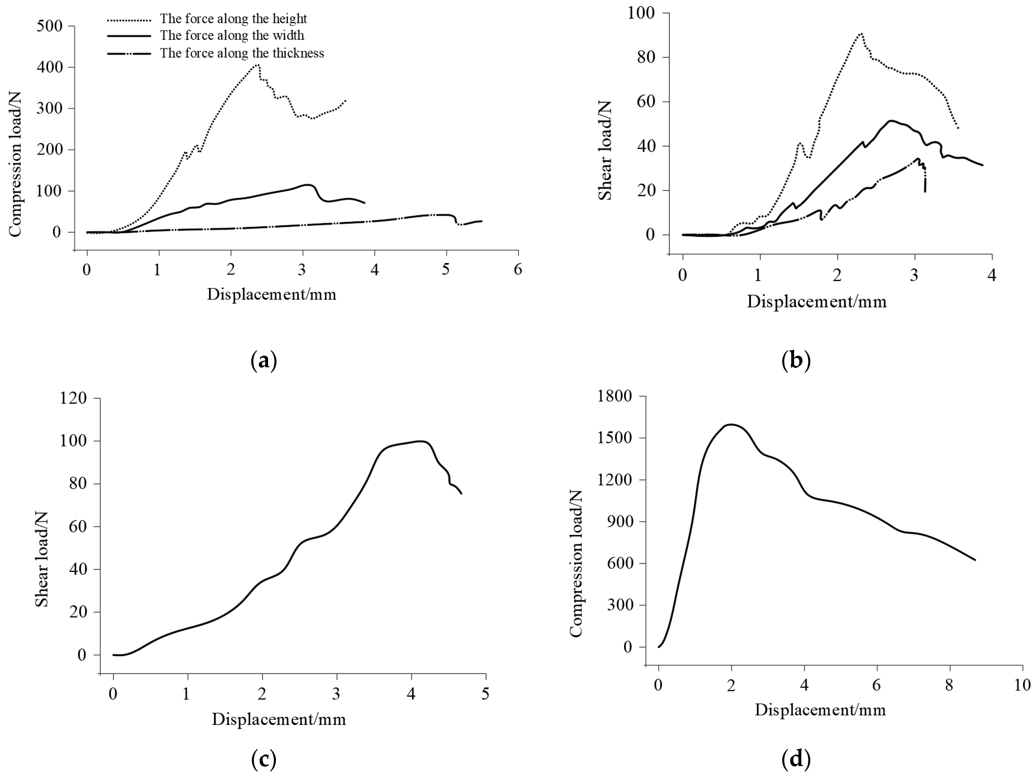
The tests were conducted at a loading rate of 6 mm/min for compression and shear, respectively, and repeated thrice, with the results averaged to minimize data errors. The force–displacement variation curves for the compression and shearing of the maize seeds and the straw are shown in Figure 10 (with the average value of the three experiments).

3.3.2. Theoretical Calculations

According to the BPM theory, the calculation formulas for normal stiffness and tangential stiffness are expressed in Equations (5) and (6), respectively [21,22].
k n = 4 3 ( 1 μ 1 2 E 1 + 1 μ 2 2 E 2 ) 1 ( r 1 + r 2 r 1 r 2 ) 1 2
k s = ( 1 2 ~ 2 3 ) k n
From the compressive strength formula and the Moore shear theory, the following relational formula is obtained:
σ = F / S
t = C + σ tan ε
Referring to relevant data, the internal friction angle and cohesion of the corn grains are 38° and 2.9 MPa, respectively, and the corresponding values of the corn stalks are 32° and 2 MPa (the grain water content is 42, and the moisture content of straw is 42) [13,23]. The particle bonding radius is generally 1.2–2 times the particle radius. The obtained values on substituting the relevant parameters into Equations (5)–(8) are listed in Table 1.

3.3.3. Determination of Simulation Parameters

Compression and shear tests were conducted on the corn kernels and stalks, and their mechanical change laws, maximum compression, and shear forces were obtained. According to the BPM theory, the normal and tangential stiffness conversion formulas were used to obtain the initial values of the bonding parameters of the corn stalks. Moreover, repeated compression and shear tests and debugging on a discrete element software were conducted. Based on the virtual simulation tests, the mechanical and apparent characteristics of the straw after compression and shear failure were compared with the physical test results, and the final parameters were obtained. The bonding parameters of the determined BPM are listed in Table 2.
In order to test the reliability of the bond model data, a model verification simulation test was carried out, and the results are shown in Table 3. Each group was tested 5 times, and the absolute deviation between the results and the actual values was within 5%. It can be seen that the bond parameters are reliable.
Considering the simulation requirements, alloy tool steel is selected for the kneading and crushing roller, and the physical parameters are imported into the EDEM software. Based on the experimental and simulation parameters in the research results of Han Dandan et al. [16], the compression and shear tests of the corn kernels and stalks, the mechanical parameters, and collision recovery coefficients of the corn kernels, stalks, and alloy tool steels are obtained. The results are listed in Table 4 [8,9,10,11,12,13,14,15,16,17,18,19,20,21,22,23,24]. To observe the crushing process of the corn kernels and the straw in more detail and record the crushing data, the update and storage time step in the EDEM software are set as 1 × 10⁻⁴ s.

4. Simulation Test and Result Analysis

4.1. Preparation of Test Materials

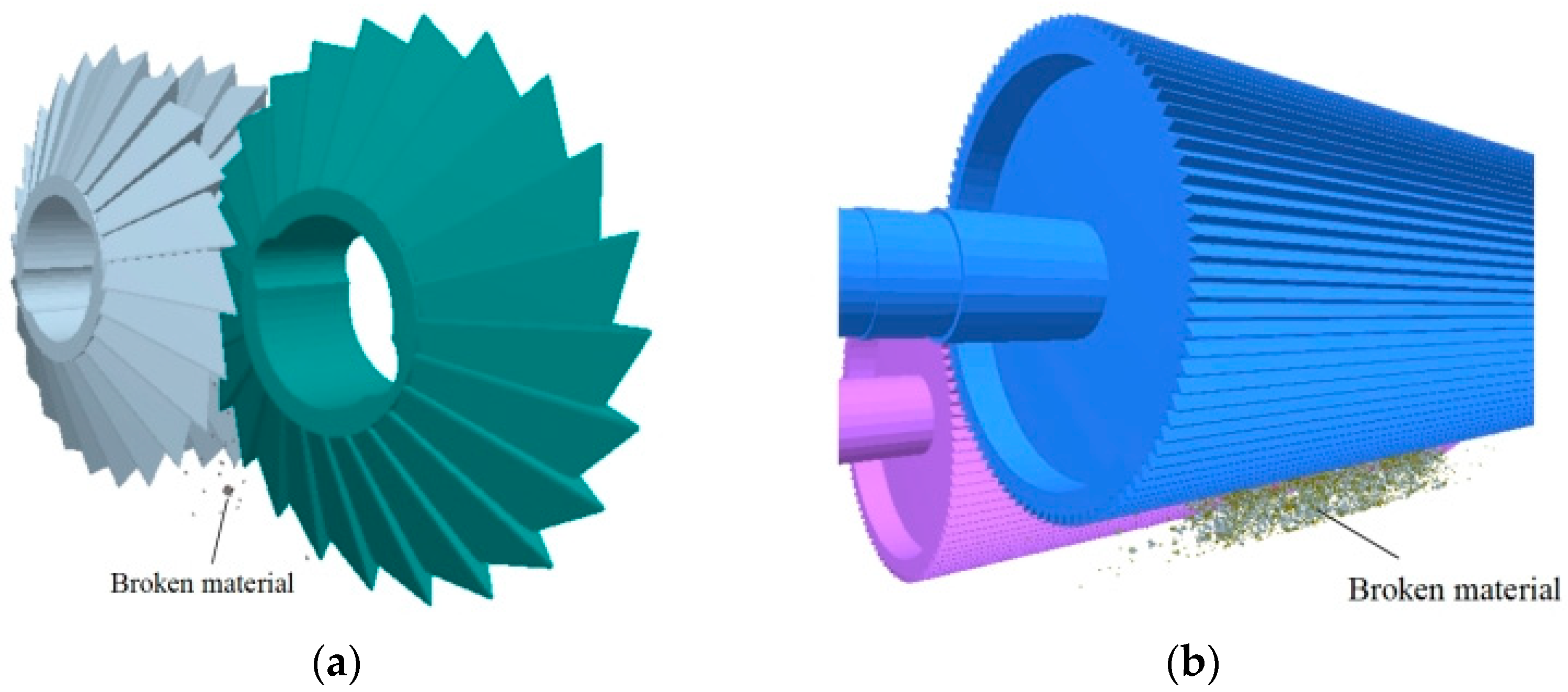
A discrete element simulation test of the corn kernel and straw rubbing and breaking is shown in Figure 11. The corn kernels and the straw cuts are generated by pellet factory and pellet replacement, and the bonding bonds are immediately added between the pellets to form a pellet-bonding model. The three-dimensional model of the crushing roller is imported into the EDEM software. After the material is generated, it enters between the two crushing rollers at a speed of approximately 15 m/s (to save the computer calculation speed, 1200 grains are generated per minute, and 600 stalks are generated per minute). The kneading and crushing are completed under the action of the differential speeds of the two rollers, and the test data and the crushing scenario are recorded in real time.

4.2. Straw Rubbing Rate and Grain Crushing Rate Measurement Standards

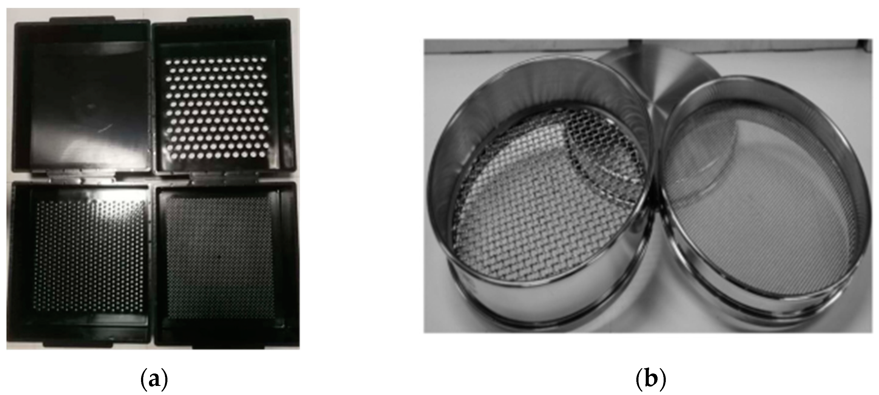
The evaluation of the crushing effect of corn silage feed typically uses a Binzhou sieve and a corn grain silage crushing scoring sieve, which measure the effect of the straw rolling and the grain crushing, respectively. The Binzhou sieve is shown in Figure 12a. The aperture of the upper sieve is 19 mm; the aperture of the middle sieve is 8 mm; and the aperture of the lower sieve is 4 mm. According to the “Technical Specification for the Evaluation of the Quality of Maize Silage Production Machinery for Maize” and the requirements of the corn silage harvester industry standard, all broken straws that can pass through the upper sieve are qualified. The grading sieve for crushing the corn silage kernels is shown in Figure 12b. The upper and lower sieves have apertures of 4.75 mm and 2 mm, respectively. A study showed the particles that pass through the 4.75 mm sieve are easier to digest by cattle compared to those through the 2 mm sieve and do not require additional chewing. Therefore, the crushed kernels passing through the 4.75 mm hole are qualified in this study [2].
In the silage corn rolling and crushing test bench for the whole plant corn rolling and crushing operation, from the outlet and at an interval of 5 min to take samples once, each group was taken three times, 1000 g each time, after mixing with the cross method to take out 1000 g sample to measure and calculate the grain crushing rate and straw rubbing rate.
At the end of the test, the grains that passed the 4.75 mm sieve were picked up, and the mass of broken grains and the mass of samples were weighed, respectively. The grain crushing rate was calculated according to the following formula.
Y 1 = G t G j × 100 %
After mechanical processing, the whole corn plant split into more than two halves lengthwise, and the cross-sectional area of each half was less than or equal to half of the cross-sectional area of the fracture. Calculate according to the following formula:
Y 2 = G r G y × 100 %
After the completion of the simulation tests, three-dimensional models of a Penn State Particle Separator and the corn grain silage crushing scoring screen are imported into the EDEM Software. The broken bond model also needs to be screened by the above two kinds of screens in EDEM software and calculated according to Formulas (9) and (10), so as to obtain the straw rubbing rate and grain crushing rate of the simulation test.

4.3. Determining Optimal Working Parameters of Each Roller

To obtain the optimal working parameters of each crushing roller type, their differential speed ratio and the speed of the active roller (higher roller speed) are selected as the experimental factors [25,26]. Using the straw rubbing rate and the grain crushing rate as the experimental inspection indicators, the effects of above two factors on the kneading and crushing performance of the disc-type crushing roller, ordinary tooth crushing roller, and spiral-notched crushing roller are analyzed. When selecting the parameters, considering the crushing requirements and the maximum power of the machine, the crushing gap is 3 mm, and the maximum speed is 5000 r/min. Quadrature rotation orthogonal simulation tests are conducted using the test factors and codes listed in Table 5. The central-composite experimental design method in the Design-Expert software is used to conduct orthogonal experiments, following which experimental plan design and data analysis are performed. The corn stalk rubbing rate and the grain crushing rate are used as the test evaluation indicators. The results of the orthogonal plan are summarized in Table 6. As shown, X1 and X2 are the factor coding values, which represent the differential speed ratio of the two rollers and the rotation speed of the active roller, respectively. Y1 and Y2 are the experimental inspection indicators, which respectively represent the straw rubbing rate (the rate of sieving through the Pennsylvania sieve) and the grain crushing rate (4.75 mm sieve grain sieving rate). Groups A–C represent the disc crushing roller, ordinary tooth-shaped crushing roller, and spiral-notched zigzag crushing roller, respectively. Each group was repeated three times, and the results were averaged.

4.4. Analysis of Effect of Simulated Crushing and Silking

Based on the measurement standards of the straw rubbing rate and the grain crushing rate, the crushing effect was classified after the simulation test, and the crushing and classification effect diagram is shown in Figure 13.
In the test process, each corn kernel bonding model is formed by bonding 305 particles, and a total of 1595 bonding bonds are formed. On average, each particle has 5.2 bonding bonds; each corn stalk is cut into sections. The bonding model comprises 2963 particles bonded together, forming a total of 13,650 bonding bonds, and each particle has an average of 4.6 bonding bonds. It can be seen that the bonding of each model is quite strong, and the reliability of the simulation test is relatively high.

4.5. Analysis of Crushing Results

The Design-Expert software is used to perform multiple regression fitting and analysis of variance, and the results are listed in Table 7. The significance levels of both the regression models for the straw rubbing rate, Y1, and grain crushing rate, Y2, are p < 0.001, indicating high significance level. The significance levels of the lack-of-fit item for both are p > 0.25, indicating a good fitting effect.
The regression equation of group A is
Y 1 = 83.49 + 0.83 × X 1 + 7.52 × X 2
Y 1 = 70.58 + 1.47 × X 1 + 11.52 × X 2
The regression equation of group B is
Y 1 = 78.08 + 1.80 × X 1 + 7.33 × X 2
Y 1 = 60.53 + 3.15 × X 1 + 10.55 × X 2
The regression equation of group C is
Y 1 = 84.45 + 1.68 × X 1 + 7.08 × X 2
Y 1 = 70.94 + 1.08 × X 1 + 8.33 × X 2
Based on the size of the variance, F, the degree of influence of each parameter on the straw rubbing rate can be determined. The effects of x2 on the straw rubbing rate and grain crushing rate are extremely significant, and the interaction of the two factors is not remarkable. The degree of influence of the two parameters in descending order is the rotating speed of the crushing roller and the differential speed ratio. The optimal working parameters of each crushing roller are determined by orthogonal experiments. For Group A, under the parameter combination of driving roller speed of 4990.6 r/min and differential speed ratio of 25.6%, the straw rubbing rate is 91.8%, and the grain crushing rate is 83.3%. For Group B, under the parameter combination of active roller speed of 5000 r/min and differential speed ratio of 27.8%, the straw rubbing rate is 87.4%, and the grain crushing rate is 78.8%. For Group C, under the parameter combination of active roller speed of 4998.5 r/min and differential speed ratio of 25.5%, the straw rubbing rate is 93.2%, and the grain crushing rate is 80.3%.
Referring to the parameter ratio obtained by the simulation orthogonal experiment, in the bench tests, the speeds of the active roller and the differential speed ratios of Groups A–C are 5000 r/min and 25%, 5000 r/min and 30%, and 5000 r/min and 25%, respectively. These are set to achieve the best work effect.

5. Verification Test

To verify the feasibility of the simulation test results, a bench verification test was conducted. The test used the silage comprehensive test bench independently developed by the team to verify the different crushing effects of the three types of crushing rollers and the shape classification of the crushed materials. The prototype parameters are listed in Table 8. The prototype structure can be seen in Figure 14. We can compare the physical objects of different crushing rollers (Figure 15).
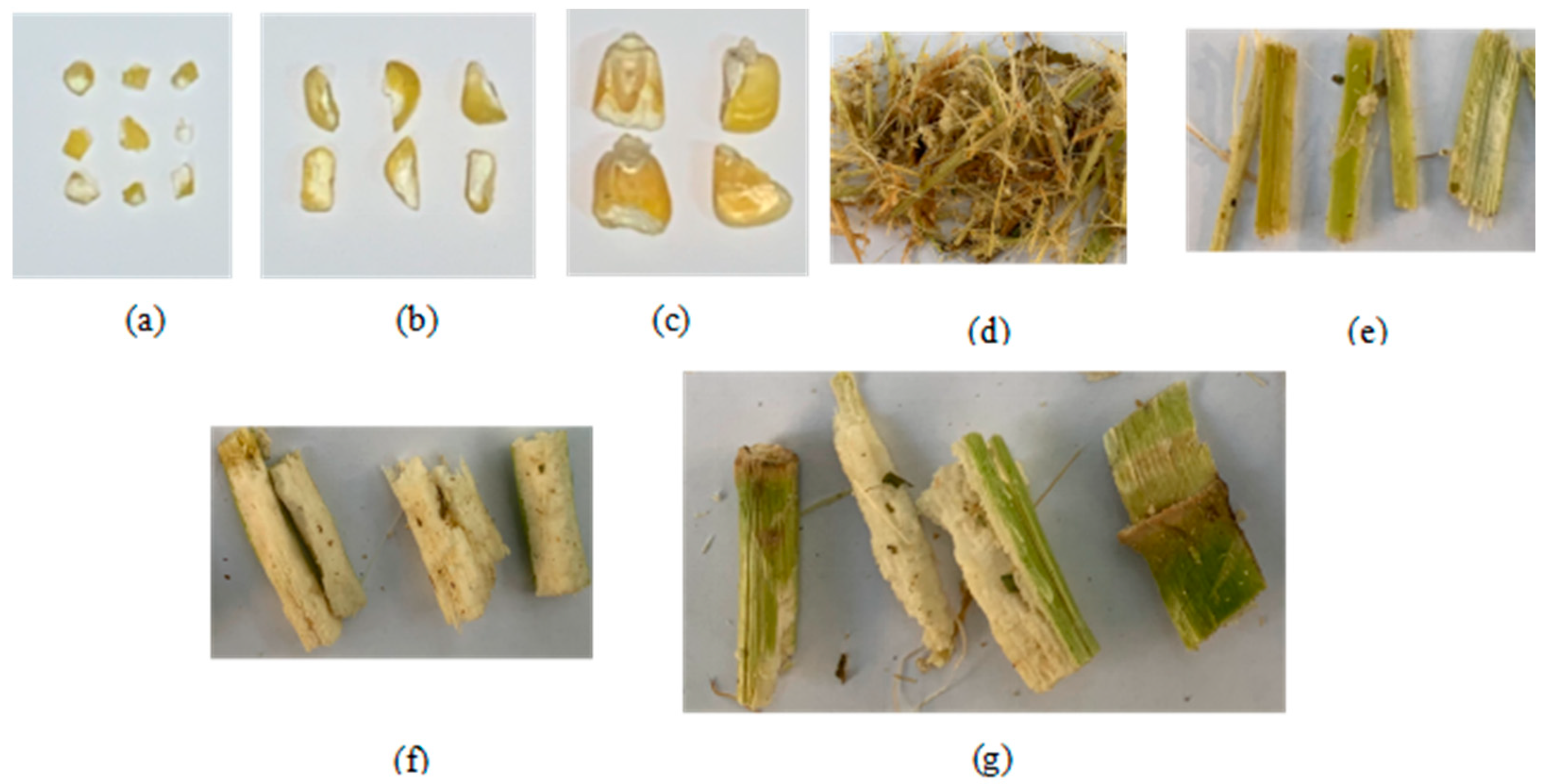
The WSM variety used in the experiment is Zhengdan 958. The harvest period is from late milk maturity to early wax maturity. The moisture contents of the grain and the straw are 41.25 and 76.58%, respectively. The test is started after the speed is set and stabilized, and a material collection bag is installed at the discharge port to collect the crushed materials. Based on the optimal parameter ratio obtained from the simulation orthogonal experiment results, the speeds of the active roller and of Groups A–C are 5000 r/min and 25%, 5000 r/min and 30%, and 5000 r/min and 25%, respectively. Under these settings, the verification tests are conducted. Fifteen whole plants of corn are placed on the conveying port each time, with an interval of 2 s between two feedings to ensure uniformity and continuity of the straw feeding. Each group of experiments is conducted for 2 min and repeated thrice. The effect of rubbing and crushing WSM is shown in the figure. As shown in Figure 16, after the end of each group of experiments, the Binzhou sieve and the corn silage grain crushing scoring screen are used to evaluate the effects of the straw rolling and grain crushing, respectively. The type and shape of the crushed materials are shown in Figure 17. Numerical simulation and experimental results are consistent.
Table 9 compares the simulated and experimental values of the stalk rubbing rate and the grain crushing rate. The deviation between the simulation and experimental values of the different types of material crushing rollers is maintained within 5%, which proves that it is feasible to apply the DEM to study corn kernels and straw crushing. To evaluate the crushing effects of the different rollers, comprehensive score, H, of the crushing effect is introduced as
H = η Y 1 + ς Y 2
With reference to the relevant requirements of the “Technical Specification for the Evaluation of the Quality of Maize Silage Machinery for Production of Whole Corn”, in this study, η is taken as 0.4, and ς is taken as 0.6 [13]. It is concluded that HA is 88.26, HB is 80.42, and HC is 87.24, and DSR group has the highest comprehensive score, making it the most suitable for harvesting WSM.
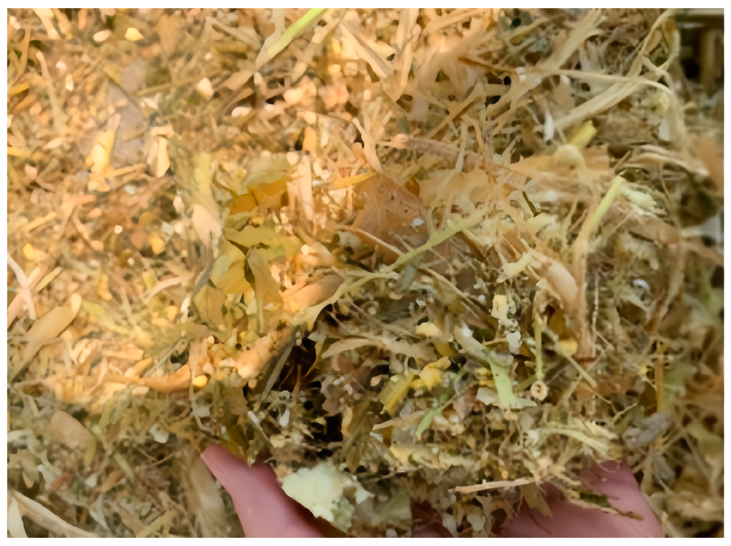
Figure 18 shows the crushing conditions of WSM in the different groups. It can be seen that the crushing effects of DCR and SNSCR are generally better than that of the ordinary tooth crushing roller. Among them, the 4.75 mm sieve of DCR achieves the highest sieving rate, reaching 87.7%. It can be seen that the V-shaped crushing gap can greatly improve the grain crushing of silage corn with higher water content. SNSCR has an additional transverse shearing effect on the material. After kneading and crushing, the effect of kneading and silking the straw is the best, and the screening rate with the Penn State Particle Separator sieve is 31.3%. The overall effect of CSCR is relatively poor. Because the ultimate goal of processing silage is to crush corn, subsequently ferment it, and finally feed livestock, it is necessary to develop crushed corn silage with a high conversion rate of the fermented crude fibers and other substances, high nutritional value, and good palatability. Exploring the technology, i.e., finding the structure and parameters of the crushing roller, with improved suitability for the kneading and crushing treatment of WSM has become the key to this research.

6. Conclusions

(1)
A mechanical analysis of the crushing process of WSM using different crushing rollers showed that a spiral-notched serrated crushing roller has a lateral shearing effect and is conducive to straw silking. DCR can increase the crushing area by 2.6–3.3 times under the same width than that of CSCR and, therefore, has the highest operational efficiency and the best crushing effect on kernels.
(2)
A BPM bonding parameter analysis was conducted on maize seeds and straw in combination with mechanical property tests. Having established the bonding model of corn grain and straw and carried out simulations based on discrete element software (EDEM) orthogonal test, the use of the Design-Expert 10.0 software for multiple regression fitting and analysis of variance and the optimum operating parameters of each crushing roller were determined: DCR set (group A), active roller speed 5000 r/min, differential ratio 25%; CSCR set (group B), active roller speed 5000 r/min, differential ratio 30%; SNSCR set (group C), driving roller speed 5000 r/min, differential ratio 25%.
(3)
Four types of straw kneading effects were considered: broken straw passing a 4 mm sieve, broken straw passing an 8 mm sieve, broken straw passing a 19 mm sieve, and broken straw not passing a 19 mm sieve. Three types of seed breaking effects were considered: broken straw passing a 2 mm sieve, broken straw passing a 4.75 mm sieve, and broken straw not passing a 4.75 mm sieve. Three categories of crushing effects of the seeds were examined: crushed seeds passing a 2 mm sieve, crushed seeds passing a 4.75 mm sieve, and crushed seeds not passing a 4.75 mm sieve.
(4)
A bench test yielded a straw rubbing rate of 89.1% and a grain crushing rate of 87.7% for DCR group, resulting in the highest overall score and the most suitability for harvesting WSM. The deviation between the simulated and experimental values of the crushing results for different types of material remained within 5%, proving the feasibility of the DEM for the study of maize seed and straw rubbing crushing.
The analysis and research in this study are limited by the simulation conditions and the techniques used to simplify and analyze the actual complex crushing process. The straw bonding model used in the study is suitable for the simulation of maize straw kneading and crushing with no knots, fixed length, and high moisture content. Moreover, only one maize variety was harvested, crushed, and analyzed in a specific harvesting period. Thus, the employed method needs to be further explored for studies of other maize varieties with different characteristics. Scholars can learn from the crushing mechanism of crushing roller in this paper to explore a new crushing roller structure which is more conducive to grain crushing and straw silking. It has implications for the design of crushing rollers and improving the quality and palatability of the crushed feed.

Author Contributions

X.M. and D.G. started the work, completed the detailed investigations, and prepared the paper with support of all the co-authors; H.L. helped us to carry out mechanical tests on corn plants; Z.W. helped us with carrying out the discrete element simulation crushing test; Q.W. and J.Z. helped us with carrying out bench tests and classifying materials. All authors have read and agreed to the published version of the manuscript.

Funding

This research was funded by the Natural Science Foundation Project of Shandong Province of China (Program No. ZR202111290044), National key research and development plan of China (Program No. 2021YFD2000502), and Shandong Province modern agricultural industrial technology system post project of China (Program No. SDAIT-02-12).

Institutional Review Board Statement

Not applicable.

Data Availability Statement

Not applicable.

Acknowledgments

We are grateful to Bin Yan and Pan Fan for their help with writing.

Conflicts of Interest

The authors declare no conflict of interest.

Nomenclature

a1Acceleration of material A
a2Acceleration of material B
CStraw cohesion: MPa
E1Elastic modulus of particle 1, Pa
E2Elastic modulus of particle 2, Pa
FPressure, N
F1Shear forces of the knife blades on the seeds 1, N
F2Shear forces of the knife blades on the seeds 2, N
Fr1Shear forces of the knife blades on the seeds r1, N
Fr2Shear forces of the knife blades on the seeds r2, N
Fx1Shear force of the roller tooth gap on the material x1, N
Fx2Shear force of the roller tooth gap on the material x2, N
F - - iResultant of forces of particle A acting on partcle B, N
f1Friction force of the teeth on the material 1, N
f2Friction force of the teeth on the material 2, N
fx1Friction force of the roller tooth gap on the material x1, N
fx2Friction force of the roller tooth gap on the material x2, N
G1Gravitational forces on the seeds 1, N
G2Gravitational forces on the seeds 2, N
GjTotal grain mass in the sample, g
GrWeight of corn stalk through Penn State Particle Searator sieve hole, g
GtTotal grain mass through a 4.75 mm sieve in a corn silage grain crushing scoring sieve, g
GyStraw sample quality, g
HComprehensive score of crushing effect
hTooth height, mm
knNormal stiffness, N/m
ksTangential stiffness, N/m
LTotal length of each roller, mm
L - - Overlap of particle A and particle B, mm
l1Distances between point P and the centers of the two disc cutters 1, mm
l2Distances between point P and the centers of the two disc cutters 2, mm
l3Ratio of single tooth width 3, mm
l4Ratio of single tooth width 4, mm
MMoisture content, %
M - - nNormal torque and tangential torque respectively n, N·m
M - - sNormal torque and tangential torque respectively s, N·m
m1Mass of the specimen before drying, g
m2Mass of the specimen after drying, g
nNumber of teeth
niTangential components
QNumber of spiral coils
R - - the cross of particle A and particle B, mm
RaRadius of the tooth top circle a, mm
RbRadius of the tooth top circle b, mm
r1Radius of particle 1, mm
r2Radius of particle 2, mm
SForced area, mm2
tCritical tangential stress, Pa
tiNormal components
v1Linear velocities of the two disc cutters at point P 1, m/s
v2Linear velocities of the two disc cutters at point P 2, m/s
Y1Straw silking rate, %
Y2Kernel fragmentation rate, %
θ1Angles between the knife blades and the horizontal direction 1, °
θ2Angles between the knife blades and the horizontal direction 2, °
θ3Angles between the knife blades and the horizontal direction 3, °
θ4Angles between the knife blades and the horizontal direction 4, °
ω1Crushing roll speed 1, r/min
ω2Crushing roll speed 2, r/min
µ1Poisson’s ratio of particle 1
µ2Poisson’s ratio of particle 2
αAngle of inclination of the sharp surface, °
βAngle of inclination of the tonal surface, °
ɤAngle of the inner cone, °
δWidth of the tooth tip, mm
τTooth pitch, mm
σCritical normal stress, Pa
ξDistance between the two rollers, mm
εInternal friction angle, °
ηWeight coefficients Y1
ςWeight coefficients Y2
φInclination angle of the spiral line, °

References

  1. Bach, A.; Joulie, I.; Chevaux, E.; Elcoso, G.; Ragués, J. Milk performance and rumen microbiome of dairy cows as affected by the inclusion of corn silage or corn shredlage in a total mixed ration. Animal 2021, 15, 100014. [Google Scholar] [CrossRef] [PubMed]
  2. Drewry, J.L.; Luck, B.D.; Willett, R.M.; Rocha, E.M.C.; Harmon, J.D. Predicting kernel processing score of harvested and processed corn silage via image processing techniques. Comput. Electron. Agric. 2019, 160, 144–152. [Google Scholar] [CrossRef]
  3. Bal, M.A.; Shaver, R.D.; Jirovec, A.G.; Shinners, K.J.; Coors, J.G. Crop processing and chop length of corn silage: Effects on intake, digestion, and milk production by dairy cows. J. Dairy Sci. 2000, 83, 1264–1273. [Google Scholar] [CrossRef] [PubMed]
  4. Jancik, F.; Kubelkova, P.; Loucka, R.; Jambor, V.; Kumprechtova, D.; Homolka, P.; Koukolova, V.; Tyrolova, Y.; Vyborna, A. Shredlage Processing Affects the Digestibility of Maize Silage. Agronomy 2022, 12, 1164. [Google Scholar] [CrossRef]
  5. Roberge, M.; Savoie, P.; Norris, E.R. Evaluation of a crop processor in a pull-type forage harvester. Trans. ASABE 1998, 41, 967–972. [Google Scholar] [CrossRef]
  6. Ferraretto, L.F.; Shaver, R.D.; Luck, B.D. Silage review: Recent advances and future technologies for whole-plant and fractionated corn silage harvesting. J. Dairy Sci. 2018, 101, 3937–3951. [Google Scholar] [CrossRef] [Green Version]
  7. Chevanan, N.; Womac, A.R.; Bitra, V.S.P.; Yoder, D.C.; Sokhansanj, S. Flowability parameters for chopped switchgrass, wheat straw and corn stover. Powder. Technol. 2009, 193, 79–86. [Google Scholar] [CrossRef]
  8. Kaliyan, N.; Morey, R.V. Constitutive model for densification of corn stover and switchgrass. Biosyst. Eng. 2009, 104, 47–63. [Google Scholar] [CrossRef]
  9. Shinners, K.J.; Jirovec, A.G.; Shaver, R.D.; Bal, M. Processing whole-plant corn silage with crop processing rolls on a pull-type forage harvester. Appl. Eng. Agric. 2000, 16, 323–331. [Google Scholar] [CrossRef]
  10. Zhang, M.; Sword, M.L.; Buckmaster, D.R.; Cauffman, G.R. Design and evaluation of corn silage harvester using shredding and flail cutting. Trans. ASABE 2003, 46, 1503–1511. [Google Scholar] [CrossRef] [Green Version]
  11. Tian, F.Y.; Xia, K.L.; Wang, J.; Song, Z.H.; Yan, Y.F.; Li, F.D.; Wang, F.D. Design and experiment of self-propelled straw forage crop harvester. Adv. Mech. Eng. 2021, 13, 16878140211024455. [Google Scholar] [CrossRef]
  12. Bai, S.; Yang, Q.; Niu, K.; Zhao, B.; Zhou, L.; Yuan, Y. Discrete element-based optimization parameters of an experimental corn silage crushing and throwing device. Trans. ASABE 2021, 63, 1019–1026. [Google Scholar] [CrossRef]
  13. Zhang, F.; Song, X.; Zhang, X.; Zhang, F.; Wei, W.; Dai, F. Simulation and experiment on mechanical characteristics of kneading and crushing process of corn straw. Trans. CSAE 2019, 35, 58–65. [Google Scholar]
  14. Johnson, L.M.; Harrison, J.H.; Davidson, D.; Mahanna, W.C.; Shinners, K. Corn silage management: Effects of hybrid, chop length, and mechanical processing on digestion and energy content. J. Dairy Sci. 2003, 86, 208–231. [Google Scholar] [CrossRef] [Green Version]
  15. Cundall, P.; Strack, D. A discrete numerical model for granular assemblies. Géotechnique 1979, 29, 47–65. [Google Scholar] [CrossRef]
  16. Han, D.; Zhang, D.; Jing, H.; Yang, L.; Cui, T.; Ding, Y.; Wang, Z.; Wang, Y.; Zhang, T. DEM-CFD coupling simulation and optimization of an inside-filling air-blowing maize precision seed-metering device. Comput. Electron. Agric. 2018, 150, 426–438. [Google Scholar] [CrossRef]
  17. Potyondy, D.O.; Cundall, P.A. A bonded-particle model for rock. Int. J. Rock Mech. Min. 2004, 41, 1329–1364. [Google Scholar] [CrossRef]
  18. Li, X.; Du, Y.; Liu, L.; Mao, E.; Yang, F.; Wu, J.; Wang, L. Research on the constitutive model of low-damage corn threshing based on DEM. Comput. Electron. Agric. 2022, 194, 106772. [Google Scholar] [CrossRef]
  19. Su, Y.; Cui, T.; Zhang, D.; Xia, G.; Cao, X.; He, X.; Xu, Y. Effects of shape feature on compression characteristics and crack rules of maize kernel. J. Food. Process. Preserv. 2019, 44, 14307. [Google Scholar] [CrossRef]
  20. Quist, J. Cone Crusher Modelling and Simulation Development of a Virtual Rock Crushing Environment Based on the Discrete Element Method with Industrial Scale Experiments for Validation. Master’s Thesis, Chalmers University of Technology, Göteborg, Sweden, 2012. [Google Scholar]
  21. Weerasekara, N.; Powell, M.; Cleary, P.; Tavares, L.; Evertsson, M.; Morrison, R.; Quist, J.; Carvalho, R. The contribution of DEM to the science of comminution. Powder. Technol. 2013, 248, 3–24. [Google Scholar] [CrossRef]
  22. Xu, J.; Xie, Z.; Jia, H. Particle flow simulation of micromechanical properties of limestone. Rock. Soil. Mech. 2010, 31, 390–395. [Google Scholar]
  23. Mousaviraad, M.; Tekeste, M.Z. Effect of grain moisture content on physical, mechanical, and bulk dynamic behaviour of maize. Biosyst. Eng. 2012, 195, 186–197. [Google Scholar] [CrossRef]
  24. Zhang, T.; Zhao, M.; Liu, F.; Tian, H.; Wulan, T. A Discrete Element Method Model of Corn Stalk and Its Mechanical Characteristic Parameters. BioResources 2020, 15, 9337–9350. [Google Scholar] [CrossRef]
  25. Cooke, K.M.; Bernard, J.K. Effect of length of cut and kernel processing on use of corn silage by lactating dairy cows. J. Dairy Sci. 2005, 88, 310–316. [Google Scholar] [CrossRef] [PubMed] [Green Version]
  26. Dias Junior, G.S.; Ferraretto, L.F.; Salvati, G.G.S.; Resende, L.C.; Hoffman, P.C.; Pereira, M.N.; Shaver, R.D. Relationship between processing score and kernel-fraction particle size in whole-plant corn silage. J. Dairy Sci. 2016, 99, 2719–2729. [Google Scholar] [CrossRef] [PubMed] [Green Version]
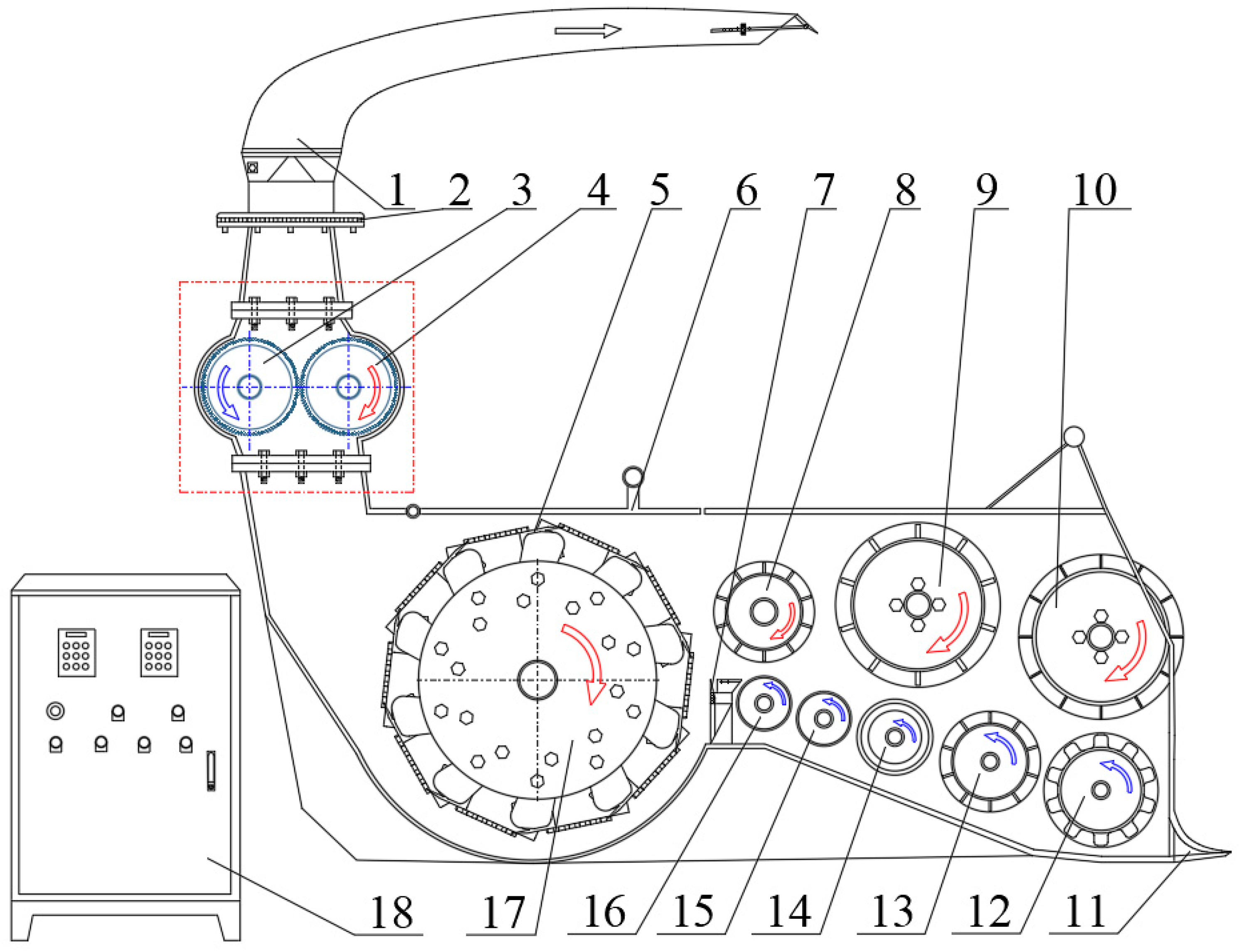
Figure 1. Structure diagram of comprehensive silage test bed. 1. Throwing barrel. 2. Throwing barrel diverter. 3. Left crushing roller. 4. Right crushing roller. 5. Cutter. 6. Cutting observation cover. 7. Fixed knife. 8. Rear toothed roller. 9. Middle toothed roller. 10. Front toothed roller. 11. Feeding inlet. 12. Pre-press roller. 13. Driven tooth roller. 14. Front smooth roller. 15. Middle smooth roller. 16. Rear smooth roller. 17. Cutting roller. 18. Console.
Agriculture 13 01276 g001
Figure 2. Disc crushing roller.
Agriculture 13 01276 g002
Figure 3. Crushing mechanism analysis. (a) Motion analysis; (b) mechanics analysis.
Agriculture 13 01276 g003
Figure 4. Two kinds of tooth crushing roller. (a) Conventional serrated crushing roller; (b) spiral-notched serrated crushing roller.
Agriculture 13 01276 g004aAgriculture 13 01276 g004b
Figure 5. Drawing of various parameters of crushing roller teeth. (a) Roller gear parameters; (b) spiral notch parameter.
Agriculture 13 01276 g005
Figure 6. Broken force analysis diagram. (a) Vertical crushing force analysis diagram of CSCR; (b) horizontal crushing force analysis diagram of SNSCR.
Agriculture 13 01276 g006
Figure 7. BPM contact model.
Agriculture 13 01276 g007
Figure 8. Corn and grain stalk model. (a) Grain entity; (b) grain discrete model; (c) grain bonding model; (d) straw bonding model.
Agriculture 13 01276 g008aAgriculture 13 01276 g008b
Figure 9. Shearing and compression test. (a) Kernel shear test; (b) kernel compression test; (c) straw shear test; (d) straw compression test.
Agriculture 13 01276 g009
Figure 10. Changing curve of load–displacement of corn straw and seeds under compression and shear process. (a) Seeds compression; (b) seeds shear; (c) straw axial compression; (d) straw radial shear.
Agriculture 13 01276 g010
Figure 11. Discrete element simulation environment. (a) DCR working environment; (b) CSCR working environment.
Agriculture 13 01276 g011
Figure 12. Kneading and crushing effect evaluation tool. (a) Penn State Particle Separator; (b) corn silage grain breaking scoring screen.
Agriculture 13 01276 g012
Figure 13. Simulation crushing effect drawing. (Aa) Broken grains passed through 2 mm sieve; (Ab) broken grains passed through 4.75 mm sieve; (Ac) broken grains that cannot pass through 4.75 mm sieve; (Ba) broken straw through 4 mm sieve; (Bb) broken straw through 8 mm sieve; (Bc) broken straw through 19 mm sieve; (Bd) broken straw that cannot pass 19 mm sieve.
Agriculture 13 01276 g013
Figure 14. Test prototype.
Agriculture 13 01276 g014
Figure 15. Real picture of crushing roll.
Agriculture 13 01276 g015
Figure 16. Rubbing and crushing effect drawing.
Agriculture 13 01276 g016
Figure 17. Crushing effect drawing. (a) Broken grains passed through 2 mm sieve; (b) broken grains passed through 4.75 mm sieve; (c) broken grains that cannot pass through 4.75 mm sieve; (d) broken straw through 4 mm sieve; (e) broken straw through 8 mm sieve; (f) broken straw through 19 mm sieve; (g) broken straw that cannot pass 19 mm.
Agriculture 13 01276 g017
Figure 18. Crushing effect of WSM by different crushing rollers. A denotes disc crushing roller (DCR); B denotes conventional serrated crushing roller (CSCR); and C denotes spiral-notched serrated crushing roller (SNSCR).
Agriculture 13 01276 g018
Table 1. Corn stalk and grain binding parameters.
ParametersValue
Corn Stalk Bonding ParametersCorn Kernel Bonding Parameters
Large Particles to Large ParticlesLarge Particles to Small ParticlesSmall Particle to Small Particle
Normal stiffness coefficient/(N·m−1)1.88 × 1076.64 × 1078.25 × 1088.13 × 108
Tangential stiffness coefficient/(N·m−1)1.02 × 1076.33 × 1076.47 × 1084.79 × 108
Critical normal stress/Pa4.71 × 1040.92 × 1051.09 × 1051.42 × 106
Critical tangential stress/Pa3.25 × 1046.55 × 1047.78 × 1048.44 × 105
Bonding radius/mm2.5211
Table 2. Bonding parameters of BPM.
ParametersValue
Corn Stalk Bonding ParametersCorn Kernel Bonding Parameters
Large Particles to Large ParticlesLarge Particles to Small ParticlesSmall Particle to Small Particle
Normal stiffness coefficient/(N·m−1)2.36 × 1078.15 × 1079.51 × 1089.86 × 108
Standard deviation3.66 × 1055.87 × 1056.81 × 1061.05 × 107
Tangential stiffness coefficient/(N·m−1)1.15 × 1077.22 × 1077.62 × 1086.15 × 108
Standard deviation2.11 × 1055.17 × 1056.33 × 1063.89 × 106
Critical normal stress/Pa5.56 × 1041.04 × 1051.54 × 1051.56 × 105
Standard deviation7.35 × 1022.08 × 1037.24 × 1031.32 × 103
Critical tangential stress/Pa3.78 × 1047.17 × 1048.27 × 1049.27 × 105
Standard deviation1.72 × 1028.31 × 1021.27 × 1031.32 × 103
Bonding radius/mm2.5211
Table 3. Validation of bond model reliability.
ProjectTest Repeats NumberMean Value/NStandard DeviationAbsolute Deviation from Actual Value
Corn kernels bonding modelMaximum shear stress along the height588.23.02.2
Maximum shear stress along the width546.52.82.5
Maximum shear stress along the thickness535.11.51.3
Maximum compressive stress along the height5383.79.53.7
Maximum compressive stress along the width5117.26.04.0
Maximum compressive stress along the thickness542.62.83.2
Corn stalks bonding modelMaximum shear stress597.33.12.8
Maximum compressive stress51588.528.72.2
Table 4. Physical properties of corn stalk and grain.
ProjectParametersValue
Straw core propertiesPoisson’s ratio0.52
Shear modulus/Pa0.6 × 108
Density/(g·cm−3)0.53
Straw skin propertiesPoisson’s ratio0.45
Shear modulus/Pa1 × 108
Density/(g·cm−3)1.17
Corn kernel propertiesPoisson’s ratio0.40
Shear modulus/Pa1.31 × 108
Density/(g·cm−3)1.43
Alloy tool steel propertiesPoisson’s ratio0.25
Shear modulus/Pa8 × 1010
Density/(g·cm−3)7.85
Straw pulp core–straw pulp coreCollision recovery factor0.165
Static friction factor0.652
Dynamic friction factor0.075
Straw rind–straw rindCollision recovery factor0.411
Static friction factor0.566
Dynamic friction factor0.062
Corn kernels–corn kernelsCollision recovery factor0.251
Static friction factor0.086
Dynamic friction factor0.072
Straw pulp core–straw skinCollision recovery factor0.552
Static friction factor0.604
Dynamic friction factor0.070
Straw core–corn kernelsCollision recovery factor0.412
Static friction factor0.485
Dynamic friction factor0.065
Straw husk–corn kernelsCollision recovery factor0.511
Static friction factor0.558
Dynamic friction factor0.052
Straw pulp core–alloy tool steelCollision recovery factor0.382
Static friction factor0.474
Dynamic friction factor0.053
Straw skin–alloy tool steelCollision recovery factor0.702
Static friction factor0.244
Dynamic friction factor0.048
Corn kernels–alloy tool steelCollision recovery factor0.702
Static friction factor0.344
Dynamic friction factor0.059
Table 5. Test factors and levels.
Test No.Factors
Differential Ratio/%Rotating Speed/(r·min−1)
−1153000
0254000
1355000
Table 6. Orthogonal test scheme and results.
Test No.Group AGroup BGroup C
LevelY1/%Y2/%LevelY1/%Y2/%LevelY1/%Y2/%
X1X2X1X2X1X2
11190.3 **83.0 **1186.1 **70.6 **1190.7 **78.7 **
21−175.9 *60.2 **1−172.5 **53.1 *1−178.8 **62.4 *
31086.6 **72.8 **1078.2 *64.5 **1086.6 *72.4 **
4−1187.8 *80.0 *−1181.9 **68.2 **−1188.8 ***78.1 *
5−1−175.6 **57.2 **−1−168.8 **45.3 **−1−175.4 **58.8 **
6−1084.4 **70.0 **−1075.3 *55.8 *−1081.8 **70.1 *
70194.4 **83.7 ***0188.3 ***72.2 **0195.8 **80.5 ***
80−175.9 *60.2 *0−171.0 *49.3 *0−178.6 **66.1 **
90082.2 *68.8 **0079.0 **62.2 *0085.5 **71.5 **
100086.5 ***70.0 *0078.2 *65.3 ***0082.6 *70.8 *
110082.3 *72.7 ***0082.3 *60.1 **0087.3 **73.8 **
120080.6 **68.1 *0075.7 ***58.8 *0080.8 ***69.2 **
130082.9 ***70.9 **0077.8 **61.5 **0085.2 **69.8 **
Note: A denotes DCR; B denotes CSCR; C denotes SNSCR. “*” indicates the standard deviation between 0.1 and 1.0 and implies significance; “**” indicates the standard deviation between 1.1 and 2.0 and implies great significance; “***” indicates the standard deviation between 2.1 and 3.0 and implies extreme significance.
Table 7. Regression model analysis of variance.
SourceGroup AGroup BGroup C
Y1/%Y2/%Y1/%Y2/%Y1/%Y2/%
FpFpFpFpFpFp
Model10.040.004356.30<0.000117.220.000833.83<0.000110.400.003921.820.0004
x10.610.46154.490.07184.730.066213.490.00792.690.14501.770.2253
x249.370.0002276.87<0.000178.47<0.0001151.29<0.000147.630.0002104.63<0.0001
x1x20.180.687201.00000.0150.90531.650.23960.0890.77410.570.4768
x120.00010.99160.0470.83492.900.13211.300.29231.520.25772.040.1962
x220.0450.83890.100.75630.450.52280.440.52780.560.47710.0780.7886
Lack of fit2.020.25330.710.59260.330.80480.370.77820.900.51421.570.3287
Note: p < 0.001 implies extreme significance; p < 0.01 implies great significance; p < 0.05 implies significance.
Table 8. Parameters of prototype.
ProjectUnitValues
Overall dimensions (length × width × height)mm2310 × 1260 × 2480
Main motorkW30
Auxiliary motorkW10
Crushing roller speedr/min 2000–5000
Speed of hobr/min 400–1000
Feeding speedm/s 0.6–3.3
Working width of crushing rollermm520
Transmission mechanism form/Worm drive, belt drive
Differential speed ratio of crushing roller%15–35
Table 9. Comparison of simulation and test rates of different material crushing rollers.
Breaking ConditionSimulation Values/%Experimental Values/%Deviation/%
AStraw rubbing rate91.889.13.0
Grain crushing rate83.387.75.0
BStraw rubbing rate87.483.64.5
Grain crushing rate78.878.30.6
CStraw rubbing rate93.291.81.5
Grain crushing rate80.384.24.6
Disclaimer/Publisher’s Note: The statements, opinions and data contained in all publications are solely those of the individual author(s) and contributor(s) and not of MDPI and/or the editor(s). MDPI and/or the editor(s) disclaim responsibility for any injury to people or property resulting from any ideas, methods, instructions or products referred to in the content.