Article

Design and Experiment of Row Cleaner with Staggered Disc Teeth for No-Till Planter

School of Agriculture Engineering and Food Science, Shandong University of Technology, Zibo 255049, China
*
Author to whom correspondence should be addressed.
Agriculture 2023, 13(7), 1373; https://doi.org/10.3390/agriculture13071373
Submission received: 28 May 2023 / Revised: 6 July 2023 / Accepted: 9 July 2023 / Published: 10 July 2023
(This article belongs to the Special Issue Advances in Modern Agricultural Machinery)

Abstract

:
In view of the large amount of wheat straw coverage and the difficulty with the high-speed working process used in traditional rotary tillage row cleaner. A row cleaner with staggered disc teeth for no-till planting was designed. It was determined that installation with a forward inclination α, horizontal declination β, and forward speed v0 of the machine were the main factors affecting the straw cleaning rate Y1 and working resistance Y2, and the range of values for structural parameters and motion parameters of the row cleaner were determined. Taking α, β, and v0 as the factors and Y1 and Y2 as the response indexes, using EDEM 2018 software to simulate the straw cleaning process under different parameters and determine the influence of each parameter on the straw cleaning performance. After performing a soil bin test, the results showed that there was no straw entanglement and blockage, and the passability was better than that of the traditional flat disc separated row cleaner. When α was 70°, β was 30°, v0 was 8 km/h, and the embedded depth h of the soil (straw) was 55 mm, the average straw cleaning rate was the highest, which was 90.59%. This study provides a new idea for the design of high-speed corn no-till planters in the Huang-Huai-Hai area of China.

1. Introduction

No-tillage seeding is an effective measure to retain straw mulching, reduce soil tillage, and protect soil structure [1,2]. It is the key technology and basic requirement for the implementation of conservation tillage [3]. The quality of the no-tillage planter’s straw-cleaning and anti-blocking performance are key to high-quality no-tillage planting operations, especially in the Huang-Huai-Hai double-cropping area of China, where the corn sowing period is short, and the wheat straw covers the surface without decomposing, with high toughness and with a tendency entangle or block the planter [4,5]. At present, no-tillage in the double-cropping area is mainly based on crushing and rotary tillage row cleaners [6,7]. The high-speed rotating rotary tiller smashes the straw and mixes it with the soil, and then sows. This straw-clearing method has large soil disturbance and high energy consumption, and the soil moisture is lost quickly; the rotary tiller is severely squeezed on the bottom and side of the soil, forming a plow bottom; the crushed straw is mixed with the soil, because of the compaction is not enough, the seeds cannot be in close contact with the soil, which affects the emergence of seedlings [8,9]. It is the focus of no-tillage sowing research in double-cropping areas to change the traditional method of crushing and rotary tillage to clear straw and prevent blockage, and provide a clean seedbed for no-tillage sowing under the conditions of small soil disturbance and low power consumption.
Mahmoud et al. [10] proposed a new promising process by applying magnetic treatment to water, which can alleviate salinity stress and improve crop productivity. The demanding use of agricultural machines would lead to grave problems concerning the quality of agricultural soils. Jalel et al. [11] proposed a permanent bed technology to improve soil conditions, and Hassen et al. [12], based on a Bayesian network, established a decision support system for risk assessment of soil compaction, which can help users to conduct causal analysis and diagnostic analysis of soil state. However, in the Huang-Huai-Hai double cropping area of China, with scattered plots and a large amount of straw coverage, an efficient straw cleaning device is more suitable for the current fieldwork environment. The straw-scraping wheel-type row cleaner adopts two oppositely installed straw cleaning discs to allow for straw cleaning of the seedbed during the no-tillage operation. The soil disturbance is small, and the operation resistance is low; it is widely used in no-tillage planters at domestic and foreign [13]. Domestic research on straw-scraping wheel-type row cleaners mainly focuses on the optimization of the structure of the straw-cleaning discs and claw teeth. Liu et al. [14] added grass allocation grids after the straw scrapers, but the straw cleaning rate was only 57.5%. Jia et al. [13] designed a stubble-cleaning mechanism with a concave claw structure based on the improvement of the plane straw cleaning discs, and the straw cleaning rate of the seedbed was 83.61%. However, there is a leakage area when using the oppositely installed straw cleaning discs, which limits the improvement of the straw cleaning rate. In view of the problems of low straw cleaning rate, unstable operation performance, and reduced working quality and working efficiency of the planter, Wang et al. [15,16] designed a star-toothed concave disk row cleaners, it adopted the front and rear staggered arrangement to reduce the leakage area, and the straw cleaning rate of the seed bet reached 92.2%. However, the processing of the star-toothed concave structure is complicated, and the front and rear staggered arrangement increases the longitudinal size of the machine.
In view of the above problems, this study shows the design of a disc tooth staggered row cleaner under the conditions of small soil disturbance and low power consumption. Upon optimizing the structure and layout of the straw cleaning discs, the leakage area can be reduced, and the straw cleaning effect can be improved. Through theoretical analysis, simulation experiments, and field performance experiments, the optimal combination of structural parameters and structural parameters was determined. Finally, through soil tank comparative experiments, the operating effectiveness of the optimal parameter combination of the device was verified, providing a theoretical reference for the design of double-season corn zero tillage seeders.

2. Materials and Methods

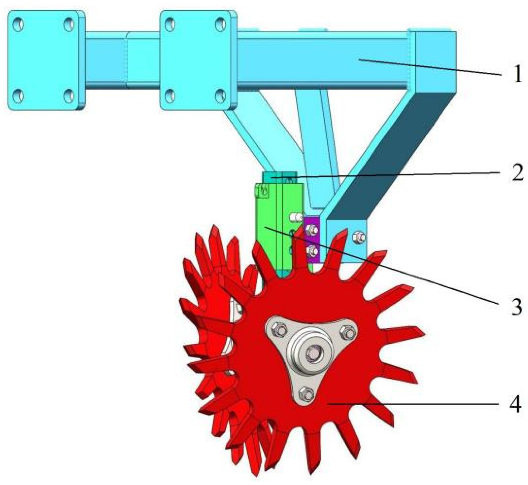
2.1. Overall Structure and Working Principle

The overall structure of the teeth of the disc staggered row cleaner is shown in Figure 1, which mainly includes a frame, a mounting frame of straw cleaning discs, a connecting frame, and two straw cleaning discs. The claws are evenly distributed around the circumference of the straw cleaning disc, and both the straw cleaning discs are symmetrically installed on both sides of the mounting frame at a certain angle to the ground. The claws of the two straw cleaning discs are staggered at the front and bottom and above the ground contact point, forming a “scissors” overlapping distribution pattern to reduce the leakage area. The straw cleaning discs mounting frame can be adjusted up and down in the connecting frame to set a suitable soil depth and reduce soil disturbance.
When the straw cleaning disc is installed, there is a certain forward inclination and horizontal declination so that the row cleaner has a certain outward expansion angle from bottom to top and from front to back. It generates thrust to both sides of the straw so that the straw moves to both sides of the opener to form a seedbed with consistent straw cleaning. The claw teeth of the straw cleaning disc contact the ground and rotate backward under the action of the friction force between the soil and the straw to achieve the picking and throwing of straw and turning of topsoil. During the working process, if one side of the straw cleaning disc is entangled with straw, the other side of the straw cleaning disc staggered with respect to the claw teeth can apply a force to it so that it can continue to rotate, effectively reducing the occurrence of straw entanglement, blockage, and stoppage.
In the double-cropping area of wheat and corn, crop stubble is the main factor that affects the quality of no-till sowing, increases the power consumption of seedbed preparation, and limits the speed of operation. This study adopts a method of avoiding stubble sowing, as shown in Figure 2. Disc teeth staggered row cleaners are installed in front of the opener of the corn no-tillage planter, as shown in Figure 3. During operation, row cleaners clean the stalks between the rows of wheat stubble and provide a clean seedbed for corn no-tillage sowing, improve the quality of sowing, reduce the power consumption required for seedbed preparation, and improve the speed of sowing operations [17,18].

2.2. Design and Analysis of Straw Cleaner

2.2.1. Analysis of Kinematic Parameter

In the process of no-till sowing operations, the effect of row cleaners on straw is related to factors such as the forward speed of the machine, the immersion depth of the straw cleaning discs, and the installation angle [19,20,21]. The kinematics of the straw cleaning tray is analyzed, the center of the straw cleaning disc is taken as the origin, the movement direction of the machine is the x-axis direction, and the Oxyz space cartesian coordinate system is established, as shown in Figure 4. The forward inclination α is the angle between the horizontal plane (xz) and the line connecting the rotation center and the meshing point of the straw cleaning disc. Horizontal deflection β is the angle between the vertical plane (xy) and the line connecting the rotation center of the straw cleaning disc and the meshing point of the straw cleaning disc. The immersion depth is h, and the two intersection points of the straw cleaning discs and the ground are m and n, respectively, then:
L m n = 2 r sin γ = 2 r 2 r h 2
In the formula: Lmn—the length of the connection line between the front and rear claw teeth and the ground intersection, mm;
r—radius of straw cleaning disc, mm;
h—immersion depth of the straw cleaning discs, mm;
γ—the angle between the line connecting the center of the straw cleaning disc and the intersection of the ground and the vertical direction, (°).
Assuming that the working width of a single straw cleaning disc is b, it can be seen from Figure 4 that the calculation formula of the working width b is [22,23]:
b = L m n sin β = 2 sin β r 2 r h 2
In the formula: b—working width of one straw cleaning disc, mm;
β—straw cleaning disc horizontal installation, (°).
The straw cleaning discs are installed in a staggered and opposite manner with respect to the claw teeth, and the straw cleaning area is shown in Figure 5:
The theoretical straw cleaning width on both sides of the straw cleaning discs is:
L B = 2 b e = 4 sin β r 2 r h 2 e
In the formula: LB—the theoretical straw cleaning width of the double-sided straw cleaning discs, mm;
e—the distance between the double intersections between the ground and the front of the double-sided straw cleaning discs, that is, the width of the overlapping area of the two straw clearing discs, mm.
It can be seen from Formula (3) that when the depth h of the straw cleaning discs is determined, the working width of the double-sided straw cleaning discs LB depends on the horizontal declination β and the width of the overlapping area of the two straw cleaning discs e.
Assume that the contact start point of the two straw cleaning disc teeth is P, the contact end point is Q, point C is the center position of the staggered contact area, and the width of the contact area is LPQ, as shown in Figure 6. LPQ is related to the center distance a, and its relationship can be represented by Formula (4).
L P Q = 2 L O P 2 L O C 2 = 2 r 2 a 2 4 sin 2 β = 2 r 2 2 r sin α sin β e 2 4 sin 2 β
In the formula: a—the center distance of the two straw cleaning discs, mm.
There is a certain overlapping area of straw cleaning between the two straw cleaning discs, which can reduce leakage area. It can be seen from Formula (4) that the smaller the center distance a, the larger the overlapping area width e and the staggered contact area LPQ, the straw cleaning discs contacts at the root of the tooth, and the disc teeth are prone to interference during rotation, resulting in them becoming stuck. The larger the center distance a, The smaller the overlapping area width e and the staggered contact area LPQ, the straw cleaning disc contacts at the tip of the tooth, which increases the moment at the root of the tooth and causes the claw teeth to break. In order to ensure that the two straw cleaning discs are staggered and contacted effectively, the contact point of the disc teeth should be located in the range above the center of the claw tooth and below the tooth top, as shown in Figure 7. Taking into account the tooth thickness and other factors, the contact point of the two claw teeth is designed to be located at dc/6 above the center point of the claw tooth, and we attain:
a = 2 sin β r 1 3 d c
In the formula: dc—claw tooth height, mm.
From Formulas (2)–(5), it can be known that when the diameter r, claw tooth height dc, and soil (straw) depth h of the straw cleaning discs are determined, the working width LB and the contact area width LPQ of the two straw cleaning discs are related to the forward inclination α and the horizontal declination β of installation. The average thickness of stalks covered on the ground during corn planting in the Huang-Huai-Hai double-cropping area of China is about 30~40 mm [24,25]; therefore, the thickness of the stalks is taken as 35 mm. In order to make the straw cleaning discs achieve the best straw cleaning operation effect when the soil disturbance is as small as possible, the straw cleaning disc’s teeth can be slightly immersed in the soil. The maximum depth of the design is 20 mm, and h is 55 mm. According to reference [26], the design radius r of the straw cleaning disc is 180 mm, and the claw tooth height dc is 70 mm.
In the actual operation process, when the forward inclination α installation is too large, a leakage area may be formed in the front, and the leakage area increases with the increase in α; if α is too small, the resistance of the straw cleaning discs will be too large. At the same time, the contact between the claw teeth and the straw will also be reduced. When the horizontal declination β is too large, the thrust of the straw cleaning discs in the forward direction of the machine will be greater than the side thrust on both sides, resulting in the resistance of the machine being too large and the stubble-picking ability reduced; when β is too small, the side thrust performance will be reduced, the straw cleaning discs cannot move the straw to the sides in a timely and effective manner, and it is easy to throw the straw to the rear, resulting in blockage of the machine. Therefore, the forward inclination α and the horizontal declination β installations should not be too large or too small. Referring to the “Agricultural Machinery Design Manual” [23], the value range is determined to be 50° ≤ α ≤ 70°, 30° ≤ β ≤ 45°.

2.2.2. Number of Claw Teeth

Too many claw teeth will easily lead to too many teeth in the soil, which will lead to excessive pressure on the straw cleaning discs and increased power consumption. At the same time, the distance between the claw teeth will be reduced, and the staggered process will easily interfere. When the number of claw teeth is too small, a larger leakage area will be generated, resulting in a reduced straw-cleaning effect. Therefore, the appropriate number of claw teeth is a key factor in reducing the power consumption of the straw cleaning operation and allowing for the interlacing of the claw teeth. Refer to the “Agricultural Machinery Design Manual” [25] to calculate the number of claw teeth:
i = 2 π r d c s c
In the formula: r—turning radius of straw cleaning disc, mm;
sc—root chord length of adjacent claw teeth, mm.
The number of claw teeth required for the straw cleaning disc can be calculated from Formula (6). In order to ensure the working strength of the row cleaner and the claw teeth can have a good effect on the straw on the ground, the number of claw teeth i = 16.

2.2.3. Shape of Claw Teeth

The distribution of the claw teeth of the straw cleaning disc is generally divided into forward inclination, backward inclination, and radial direction [13,27]. The forward-inclined claw teeth can easily cause the straw to fall between the seedbeds or cause high-speed straw entanglement. However, the backward-inclined claws are easy to stubble when rotating at a low speed, and the straw is difficult to fall off when rotating at a high speed, resulting in a blockage. Radial claw teeth are good for straw removal, picking, and other operations, especially in the form of staggered distribution of disc teeth; no matter whether a low speed or high speed is used, it is not easily blocked. It is difficult to allow for the interleaving of the claw teeth with the forward or backward claw teeth, which is easy to cause the straw cleaning discs to be stuck and stopped. Therefore, the radial claw tooth distribution is selected in this paper to achieve the preset working effect.
The radial claw teeth are designed in a trapezoidal pattern, with the left and right edges symmetrical along the center line of the teeth. As shown in Figure 8, the claw tooth gradient angle τ should not be too large, which will lead to too large friction f1, so that it is easy to accumulate straw here and cause blockage.
F s sin 90 ° σ τ f 2 + f 1 cos 90 ° σ τ
In the formula: Fs—The pressure of the claw tooth on the straw, N;
τ—claw tooth gradient angle, (°);
σ—at this moment, the angle between the claw tooth and the normal line is shown in Figure 6, (°);
f1—the friction of the claw tooth on the straw, N;
f2—the friction of the ground on the straw, N.
It can be seen from Formula (7) that if the claw tooth gradient angle τ is too large, the pressure Fs on the straw will decrease, thereby reducing the throwing effect on the straw. Therefore, combined with the existing studies [15,28,29], set the claw tooth gradient angle τ = 5°.

2.2.4. Blade Shape of Claw Teeth

The top of the claw teeth is designed as a blade, which is helpful for breaking the solid soil layer and cutting off the straw. As shown in Figure 8, the blade height dt is:
d t = l s 2 tan δ
In the formula: dt—claw tooth blade height, mm;
ls—claw tooth thickness, mm;
δ—blade bevel, (°).
The larger the tooth thickness, the larger the contact area of soil breaking, and the greater the resistance to soil entry; the smaller the tooth thickness, the smaller the strength of the claw teeth, and it is easy to press the straw into the soil. Therefore, according to the references [16,30] and the actual soil conditions in the Huang-Huai-Hai area of China, set claw tooth thickness ls = 13 mm. In order to achieve the best ground-breaking effect and reduce power consumption, set the blade bevel δ = 30° and the blade inclination angle ζ = 60°.

2.3. Experiment Method

In order to analyze and obtain the optimal design parameter combination, explore the characteristics of the working quality and working resistance of the row cleaner, and design a virtual simulation orthogonal test for the row cleaner. According to the value range of the installation angle of the straw cleaning disc, the forward inclinations of the straw cleaning disc are designed to be 50°, 60°and 70°, and the horizontal declinations are 30°, 37.5°and 45°. The machine’s forward speed is designed to be 6 km/h, 8 km/h, and 10 km/h, using the Design-Expert 10, using the three-factor and three-level Box–Behnken test; the test factors and levels are shown in Table 1.

2.4. EDEM Simulation Test

The 3D model of the disc teeth staggered row cleaner was established, and the multi-body coupling dynamics model of the interaction of “row cleaner-soil-straw” was established by discrete element simulation software EDEM 2018. In the actual operation process, the effect of straw cleaning is not only related to the forward inclination and horizontal declination of the installation of the straw cleaning discs, but it is also affected by the forward speed of the machine v0 [31,32,33]. Therefore, taking the forward inclination, horizontal declination, and forward speed as the test factors and taking the straw cleaning rate and working resistance as the main response indexes, the operation performance of the straw cleaning device was simulated. Moreover, the rationality of the design of the structure parameters and motion parameters of the row cleaner was verified by the three-factor and three-level rotation orthogonal test in pursuit of the optimal combination of structural parameters and making preliminary preparations for field experiments.

2.4.1. Setting of Simulation Test Conditions

Use the software SolidWorks 2016 to carry out 1:1 solid modeling of the key components of the row cleaner, delete the parts that are not important to the operation process to simplify the row cleaner, and save it in .STL format, and import it into the Geometry of EDEM, the simulation model shown in Figure 9 is obtained. The material is 45 steel, the Poisson’s ratio is 0.31, the shear modulus is 7.8 × 10¹⁰ Pa, and the density is 7800 kg/m3.

2.4.2. Construction of the Simulation Model

In order to simulate the field test conditions and optimize the simulation process, the soil particles, straw particles, and soil bin models were reasonably simplified. A small ball with a diameter of 8 mm was used as the soil particle model with a Poisson’s ratio of 0.38, a shear modulus of 1 × 10⁶ Pa, and a density of 1850 kg/m3. According to the actual straw coverage in the field, the straw was sampled and observed. Finally, 47 small balls with a diameter of 5 mm and a distance between the centers of 2.5 mm were selected to form particles with a length of 120 mm as the particle simulation model of straw. Its Poisson’s ratio is 0.4, the shear modulus is 1 × 10⁶ Pa, and the density is 241 kg/m3. The soil of the Huang-Huai-Hai double-cropping area of China is loess type, and the soil is loose. Based on a comprehensive literature review [26,34], the mechanical relationship model between particles is set as the Hertz–Mindlin non-sliding contact model. The contact parameters of the simulated materials are shown in Table 2.
The EDEM 2018 is used to establish a virtual simulation soil bin. According to the measurement of the field straw coverage before corn sowing in the Huang-Huai-Hai area of China, the size of the particle factory of the soil layer and the straw layer is set to 2000 mm × 700 mm, the thickness of the soil layer is set to 95 mm, and the thickness of the straw layer is set to 35 mm. The size of the soil bin is set to 2500 mm × 700 mm × 140 mm to ensure that sufficient particles can be generated in the soil bin for simulation, as shown in Figure 9. Removal of the upper plane of the soil trough and the two planes in the forward direction of the machine was conducted to ensure a more accurate particle-cleaning effect. The soil particles are only free to settle and stack under their own weight, and the required load is calibrated above the soil particles so that it can achieve the same effect as the actual soil, ensuring the accuracy of the simulation process [35,36].

2.4.3. Simulation Test Process

According to the design requirements, set the straw cleaning discs into the soil (straw) depth of 55 mm; set the grid size to automatic identification and setting; set the fixed time step of the virtual simulation process to the automatic time step, and the total time is 11 s.
As shown in Figure 10, at the beginning of the virtual simulation process, the row cleaner is located on the side of the soil bin, soil particles are generated in 0~3 s, straw particles are generated in 4~8 s, and the straw cleaning process is performed in 9~11 s. Among them, 3~4 s and 8~9 s are set as intermittent times to ensure that the performance of soil particles and straw particles can reach the preset effect.

2.4.4. Simulation Testing Methods

Referring to “Technical Specifications of Quality Evaluation for No-tillage Drilling Machinery” (NY/T1768-2009) [37], combined with the actual corn sowing operation requirements, the straw cleaning rate and the working resistance of the straw cleaning discs were selected as the evaluation level of the test.
  • Working resistance
The working resistance of the straw cleaning discs can be monitored by using the graph module in the analyst option of the EDEM 2018, and the statistical change graph of its “Force-Time” can be drawn, and the average value of its force can be calculated, as shown in Figure 11.
2.
Straw cleaning rate
The quantitative change of straw particles before and after the virtual simulation operation can be obtained in the solve report module of the EDEM 2018. As shown in Figure 12, a suitable cleaning area is selected for quantitative calibration, and the straw cleaning rate in the area is calculated.
η = 1 N 1 N × 100 %
In the formula: η—straw cleaning rate, %;
N—quantity of straw particles before virtual simulation operation;
N1—quantity of straw particles after virtual simulation operation.

3. Results and Analysis

3.1. Discrete Element Simulation Test Results and Optimization

The simulation test scheme and results are shown in Table 3, and Design-Expert was used for data processing and statistical analysis.
Quadratic regression analysis and multiple regression fitting were carried out on test data, significant influencing factors were screened out, the regression equation of the test index straw cleaning rate Y1 and working resistance Y2 was obtained, and their significance was tested. The constant in the equation is the result of software fitting.
The variance analysis of the straw cleaning rate is shown in Table 4. The insignificant factors in the quadratic term and the square term are excluded (p = 0.05), and the overall model of the test is extremely significant (p < 0.01). The factors α, v0, and βv0 were extremely significant, and the factor β was significant at p = 0.05. The significance of each factor from large to small is the forward speed, the forward inclination, and the horizontal declination of the straw cleaning disc. The regression equation of straw cleaning rate Y1 is:
Y 1 = 90.53 + 0.85 α + 0.78 β + 1.37 v 0 1.37 β v 0
Upon analyzing the straw cleaning rate Y1, it can be seen from Formula (10) that the horizontal declination and the forward speed of the machine have an interactive effect on the straw cleaning rate. The fixed forward inclination is 0 level, it can be obtained that within the preset value range, the straw cleaning rate is positively correlated with the forward speed of the machine and negatively correlated with the horizontal declination; that is, the smaller the horizontal declination, the faster the forward speed of the machine, the higher the straw cleaning rate, and the more significant the effect of the forward speed of the machine on it. By selecting different levels of forward declination angle, it can be obtained that the straw cleaning rate is positively correlated with horizontal declination.
The variance analysis of working resistance Y2 is shown in Table 5, and the overall model of the test is extremely significant (p < 0.01). The factors β, v0, αβ, αv0, α2, β2, and v02 were extremely significant, and the factor βv0 was significant at p = 0.05. The significance of each factor from large to small is the horizontal declination β, the forward speed of the machine v0, and the forward α. The regression equation is:
Y 2 = 182.44 + 4.21 α + 27.05 β + 17.31 v 0 + 18.43 α β + 16.95 α v 0 15.03 β v 0 + 22.26 α 2 33.32 β 2 + 18.60 v 0 2
Upon analyzing the working resistance Y2, it can be seen from Formula (10) that the interaction factors between the factors have a significant impact on the working resistance. The forward speed of the machine is 0 level, and it can be obtained that within the preset value range, the larger the forward inclination and the smaller the horizontal declination, the smaller the working resistance will be. When the forward speed is smaller, the contact time between the straw cleaning discs and the soil is longer, and it is easier for the soil to accumulate in the front, resulting in an overall increase in the working resistance. However, when the forward speed is higher, the throwing effect of the straw cleaning discs on the soil is reduced, and the forward dozing effect is enhanced, which leads to an increase in the working resistance.
In order to obtain the optimal combination of structure and motion parameters of the disc teeth staggered row cleaner, the optimal design of the experimental factors was carried out, and the principle of improving the straw cleaning rate and reducing the working resistance was followed, according to the boundary conditions of the experimental factors and the actual operation experience, the multi-objective variable optimization method is used to establish the parameter-constrained objective function model.
max y 1 α , β , v 0 min y 2 α , β , v 0 s . t . 50 ° α 70 ° 30 ° β 45 ° 6   km / h v 0 10   km / h
Based on the above analysis, it can be seen that the larger the forward inclination, the smaller the horizontal declination, the faster the forward speed of the machine, and the higher the straw cleaning rate; but at the same time, the larger the forward inclination, the smaller the horizontal declination, and the speed of the machine is 0 level, working resistance is minimal. Based on Design-Expert, the parameters in the objective function are optimized and solved, and a set of reasonable optimization parameter combinations are selected from the results according to the actual operation requirements. The optimal combination obtained is α3β1v02, that is, the forward inclination is 70°, the horizontal declination is 30°, and the forward speed of the machine is 8 km/h. At this time, the straw cleaning rate is 90.60%, and the working resistance is 130 N. According to the optimization results, the virtual simulation verification test was carried out. The straw cleaning rate was 90.87%, and the working resistance was 136.4 N, which was basically consistent with the optimization results.

3.2. Field Test Verification

In order to verify the actual operating performance of the disc teeth staggered row cleaner and its advantages compared with the traditional flat disc separated row cleaner, a soil bin test was conducted in the soil bin laboratory of Shandong University of Technology in October 2021. The soil type was loam, and the temperature in the laboratory was 20~26 °C during the experiment.
Before the test, the straw was pre-laid on the ground, and the laying range was a long strip area of 20 m × 1 m, and then the parameters of straw and soil were measured. Table 6 shows the main parameters obtained in the soil bin. Among them, soil moisture content and soil temperature were measured with a TZS-IIW soil moisture and temperature measuring instrument; soil compaction was measured with a TJS-450G soil compaction instrument.

3.2.1. Test Methods

As shown in Figure 13, the disc teeth staggered row cleaner and the flat disc separated row cleaner were installed on the frame of the soil bin testing vehicle, respectively, so that the test could be carried out under the same working conditions. The test was performed by aligning the row cleaner with the preset ditching area, adjusting the immersion depth of 55 mm, and setting the forward speed of the soil bin testing vehicle to 8 km/h. The following indicators were measured and calculated accordingly during and after the test.
  • Straw cleaning rate of seedbed
Before the start of the test, the five-point sampling method was used to select points in the stable operation area randomly, and the electronic scales were used to weigh all the straws in the same area of each sampling point before and after the operation to obtain the initial mass G0 and the post-operation mass G1, the straw cleaning rate in the measurement area is further calculated. Each group of row cleaner test was repeated five times, and the average cleaning rate of each group was obtained [38].
λ = 1 G 1 G 0 × 100 %
In the formula: λ—straw cleaning rate of the seedbed, %;
G0—straw quality in the frame before operation, kg;
G1—straw quality in the frame after operation, kg.
2.
Working width
After the test, use the five-point sampling method to select five observation points, measure the working width of the points with a tape measure, and take the average value, as shown in Figure 14.
3.
Passability
During the process, the row cleaner is at the preset speed, and the operation process of the teeth of the disc staggered row cleaner and the flat disc separated row cleaner are monitored. According to the agricultural industry standard “Technical Specifications of Quality Evaluation for No-tillage Drilling Machinery” (NY/T1768-2009) [37] and the performance testing requirements of no-till planters at the agricultural machinery appraisal station of the Ministry of Agriculture, observe whether the two sets of row cleaners can complete the operation normally, and the number of times of blockage or stoppage. The number of rotations was carried out five times for each group of row cleaners, and their performance was compared.

3.2.2. Test Results and Analysis

The test results are shown in Table 7. During the soil bin test, the disc teeth staggered row cleaner did not become blocked and stopped, the average cleaning rate was 90.59%, and the working width was 169.6 mm; There were two minor blockages and one moderate blockage during the operation of the flat disc separated row cleaner, the average cleaning rate was 65.65%, and the working width was 90.8 mm. It can be seen that the disc teeth staggered row cleaner forms a meshing structure similar to “scissors” in the middle of the seedling belt, forming a staggered and overlapping state, which is more conducive to tearing the straw in the middle and throwing it to the two sides. Therefore, the leakage area easily formed by the traditional flat disc separated row cleaner is eliminated, and the straw within the working width is more fully cleaned so as to further improve the straw cleaning rate of the seedbed. At the same time, the cutting edge set on the top of the claw teeth of the straw cleaning discs of the disc teeth staggered row cleaner is more helpful for cutting the straw and cutting into the soil, and the operation performance is better.
In addition, since the straw cleaning discs are set so that the claws are staggered, if one side of the straw cleaning disc is blocked and stopped during the operation, the other sides discs will be able to provide torque to it through the meshing point, causing it to break the blockage and resume the rotation again. Therefore, compared with the multiple blockages found in the control group during the test, the experimental group did not have such a situation.
Upon comparing data obtained after the soil bin test with the results obtained from the previous virtual simulation experiment, it can be seen that the results of the two are basically the same, but the straw cleaning rate of the soil bin test is slightly lower than that of the simulation experiment. The reason may be that the soil moisture content is too large during the soil bin test, while the straw moisture content is slightly smaller, but the error mean is acceptable. The soil bin test results show that the disc teeth staggered row cleaner can achieve a good operation effect, and the operation quality can meet the agronomic requirements of no-tillage seeding operation.

4. Discussion

This article studies methods to improve the effectiveness of straw cleaning and blockage prevention during the zero-tillage sowing process of corn in the double cropping area. As far as we know, there is currently relatively little research on interlocking disc tooth type-opposed straw-cleaning devices, which have a certain degree of innovation and scientificity at present. Jia et al. [13] designed and developed a concave disc-type straw cleaning and anti-blocking device. This device uses a front and rear misaligned concave disc, which can increase the overlapping operation area, reduce the missed cleaning area, and throw the straw away along the concave curve, effectively carrying out straw cleaning operations. The similarity with this design lies in the use of opposed discs as key components and the addition of overlapping work areas in the middle through different methods to reduce missed areas. The difference lies in the structures of the straw cleaning disc, and the principle of reducing the leakage area is also different. The specific performance is as follows: This design innovation has designed the installation method of the straw cleaning disc, with the disc teeth alternating with each other, reducing the leakage area and improving the occurrence of congestion. Due to the differences in straw coverage and soil conditions, the experimental results are not comparable. From the soil tank comparison experiment, it can be seen that the average straw cleaning rate of the traditionally opposed disc non-staggered straw cleaning device is 65.65%, and there has been congestion during the experiment process; The average straw cleaning rate of the disc tooth staggered straw cleaning device is 90.80%, and there was no significant congestion during the experimental process, resulting in better operational performance.
This study has conducted some innovative device structural designs, but there are also some limitations. The specific content is as follows.
The mainstream discrete element model of wheat straw is currently a rigid body. In the future, detailed parameters should be determined through physical property tests, and a flexible test model should be set to further improve simulation accuracy.
The passive straw cleaning device designed in this article still carries the risk of straw congestion. It is necessary to further design a low-energy consumption and high-performance active straw cleaning device to further reduce congestion and improve sowing accuracy.

5. Conclusions

  • Complete the overall structural design of the straw cleaning and anti-blocking device of the disc teeth staggered seeder, which is mainly composed of two circular straw cleaning disks installed alternately by disc teeth through appropriate installation angle adjustment. Through kinematics analysis, establish its collaborative parameter model, verify the feasibility of the device through discrete element model establishment and simulation tests, and find out the best operating parameter combination of the combinations available. It can greatly improve the congestion situation during the corn no-tillage sowing process;
  • The key collaborative operation parameters of the device were optimized through regression analysis. When α = 70°, β = 30°, and v0 = 8 km/h, the device has the highest straw cleaning rate (95.87%);
  • In order to verify the reliability, scientificity, and feasibility of the straw cleaning and blocking prevention device of the disc tooth staggered seeder, a soil groove test was conducted. Compared with the traditional double disc opposed non-staggered straw cleaning device, when the straw coverage is 0.9375 kg/m2, the disc tooth staggered device does not block, and the average cleaning rate is 90.59%. The operating effect is significantly better than the traditional double disc opposed non-staggered straw cleaning device, verifying the feasibility of the disc tooth staggered device. It is basically consistent with the results of the discrete element simulation test, which verifies the scientificity, feasibility, and accuracy of the quadratic polynomial regression model.

Author Contributions

Conceptualization, Y.Z. (Yinping Zhang); methodology, Y.Z. (Yinping Zhang) and X.L.; software, X.L., H.H. and B.W.; validation, Y.Z. (Yinping Zhang), H.Z. and D.G.; formal analysis, Y.Z. (Yinping Zhang) and Y.Z. (Yuzi Zhang); writing—original draft preparation, X.L.; writing—review and editing, Y.Z. (Yinping Zhang). All authors have read and agreed to the published version of the manuscript.

Funding

The work was supported by the National Key R&D Program of China (2021YFD2000401-2), the Innovation Capability Enhancement Project for Technological Small and Medium-sized Enterprises (2023TSGC0339), the Modern Agricultural Industrial System of Shandong Province (SDAIT-02-12).

Institutional Review Board Statement

Not applicable.

Data Availability Statement

The data presented in this study are available on request from the corresponding author.

Conflicts of Interest

The authors declare no conflict of interest.

References

  1. Zhang, Y.P.; Wang, Z.W.; Diao, P.S.; Du, R.C.; Li, H.W.; Yao, W.Y. Short-term effects of mechanical and ecological tillage pattern on physical and chemical characteristics of soil in arid area. Trans. Chin. Trans. Chin. Soc. Agric. Mach. 2018, 49, 45–55. [Google Scholar]
  2. Malasli, M.C.; Ahmet, C. Disc angle and tilt angle effects on forces acting on a single-disc type no-till seeder opener. Soil Tillage Res. 2019, 194, 104304. [Google Scholar] [CrossRef]
  3. He, D.; Li, H.W.; Chen, H.T.; Lu, C.Y.; Wang, Q.J. Research progress of conservation tillage technology and machine. Trans. Chin. Soc. Agric. Mach. 2018, 49, 1–19. [Google Scholar]
  4. Hu, H.N.; Li, H.W.; Li, Q.J.; Wang, J.; He, C.Y.; Lu, Y.B.; Liu, W.P. Anti-blocking performance of ultrahigh-pressure waterjet assisted furrow opener for no-till seeder. Int. J. Agric. Biol. Eng. 2020, 13, 64–70. [Google Scholar] [CrossRef]
  5. Zhang, Y.P.; Du, R.C.; Diao, P.S.; Yang, S.D. Experiment of no-tillage and drought direct sowing rice and feasibility analysis in Shandong Province. Trans. Chin. Soc. Agric. Eng. 2016, 32, 24–30. [Google Scholar]
  6. Shinoto, Y.; Otani, R.; Matsunami, T.; Maruyama, S. Analysis of the shallow root system of maize grown by plowing upland fields converted from paddy fields: Effects of soil hardness and fertilization. Plant Prod. Sci. 2021, 24, 297–305. [Google Scholar] [CrossRef]
  7. Mairghany, M.; Yahya, A.; Adam, N.M.; Su, A.S.; Aimrun, W.; Elsoragaby, S. Rotary tillage effects on some selected physical properties of fine textured soil in wetland rice cultivation in Malaysia. Soil Tillage Res. 2019, 194, 104318. [Google Scholar] [CrossRef]
  8. Zhang, X.R.; Guo, L.; Li, H.W.; He, J.; Zhang, L.R. Experiment on the anti-blocking technology in no-tillage wheat seeding. Adv. Mater. Res. 2012, 1671, 472–475. [Google Scholar] [CrossRef]
  9. Latifmanesh, H.; Deng, A.; Nawaz, M.M.; Li, L.; Chen, Z.; Zheng, Y.; Wang, P.; Song, Z.; Zhang, J.; Zheng, C.; et al. Integrative impacts of rotational tillage on wheat yield and dry matter accumulation under corn-wheat cropping system. Soil Tillage Res. 2018, 184, 100–108. [Google Scholar] [CrossRef]
  10. Hozayn, M.; Elaoud, A.; Attia, A.A.; Ben, S.N. Effect of magnetic field on growth and yield of barley treated with different salinity levels. Arab. J. Geosci. 2021, 14, 701. [Google Scholar] [CrossRef]
  11. Jalel, R.; Elaoud, A.; Ben, S.N.; Chehaibi, S.; Ben, H.H. Modeling of soil tillage techniques using Fruchterman–Reingold Algorithm. Int. J. Environ. Sci. Technol. 2021, 18, 2987–2996. [Google Scholar] [CrossRef]
  12. Ben, H.H.; Elaoud, A.; Masmoudi, K. Modeling of agricultural soil compaction using discrete Bayesian networks. Int. J. Environ. Sci. Technol. 2020, 17, 2571–2582. [Google Scholar]
  13. Jia, H.L.; Liu, X.; Yu, H.B.; Lu, Y.; Guo, C.J.; Qi, J.T. Simulation and experiment on stubble clearance mechanism with concave claw-type for no-tillage planter. Trans. Chin. Soc. Agric. Mach. 2018, 49, 68–77. [Google Scholar]
  14. Liu, Z.P.; Tian, M.; Yang, S.X.; He, R.Y. Design of a grass separation equipment with driven rotating tooth disk. J. South China Agric. Univ. 2018, 39, 120–124. [Google Scholar]
  15. Wang, Q.; Jia, H.L.; Zhu, L.T.; Li, M.W.; Zhao, J.L. Design and experiment of star-toothed concave disk row cleaners for no-till planter. Trans. Chin. Soc. Agric. Mach. 2019, 50, 68–77. [Google Scholar]
  16. Wang, Q.; Tang, H.; Zhou, W.Q.; Wang, J.W. Design and experiment of automatic width control row cleaners. Trans. Chin. Soc. Agric. Mach. 2021, 52, 25–35. [Google Scholar]
  17. Zhang, Y.P.; Du, R.C.; Diao, P.S.; Yang, S.D.; Wang, Z.W. Design and experiment of wide band seeding rice seeder with reversed stubble cleaning and anti-blocking. Trans. Chin. Soc. Agric. Eng. 2017, 33, 7–13. [Google Scholar]
  18. Wang, Q.J.; Li, H.W.; He, J.; Li, W.Y.; Liu, A.D. Effects of wide-ridge and narrow-row no-till cultivation on soil water and maize yield. Trans. Chin. Soc. Agric. Eng. 2010, 26, 39–43. [Google Scholar]
  19. Galibjon, M.; Dimitris, S.; Alim, S.; Hans, W. Dynamic performance of a no-till seeding assembly. Biosyst. Eng. 2017, 158, 64–75. [Google Scholar]
  20. Zhang, B.P. Sowing Machinery Design Principle; China Machine Press: Beijing, China, 1982; pp. 389–403. [Google Scholar]
  21. Matin, M.A.; Fielke, J.M.; Desbiolles, J.M. Torque and energy characteristics for strip-tillage cultivation when cutting furrows using three designs of rotary blade. Biosyst. Eng. 2015, 129, 329–340. [Google Scholar] [CrossRef]
  22. Lin, J.; Liu, A.D.; Li, B.F.; Li, B.; Zhao, D.F.; Lu, C.Y. 2BG-2 type corn ridge planting no-till planter. Trans. Chin. Soc. Agric. Mach. 2011, 42, 43–46. [Google Scholar]
  23. Bao, W.Y. Study on Key Parts and Holistic Device of the No-till Planter of the Ridge Cropping System in Northeast Area of China. Ph.D. Thesis, Shenyang Agricultural University, Shenyang, China, 2009. [Google Scholar]
  24. Wang, W.W.; Zhu, C.X.; Chen, L.Q.; Li, Z.D.; Huang, X.; Li, J.C. Design and experiment of active straw-removing anti-blocking device for maize no-tillage planter. Trans. Chin. Soc. Agric. Eng. 2017, 33, 10–17. [Google Scholar]
  25. Chinese Academy of Agricultural Mechanization Sciences. Agricultural Machinery Design Manual; China Agricultural Science and Technology Press: Beijing, China, 2007; pp. 288–299. [Google Scholar]
  26. Cao, X.P.; Wang, Q.J.; Li, H.W.; He, J.; Lu, C.Y. Combined row cleaners research with side cutter and stubble clean disk of corn no-till seeder. Trans. Chin. Soc. Agric. Mach. 2021, 52, 36–44. [Google Scholar]
  27. Tagar, A.A.; Ji, C.Y.; Adamowski, J.; Malard, J.; Qi, C.S.; Ding, Q.S.; Abbasi, N.A. Finite element simulation of soil failure patterns under soil bin and field testing conditions. Soil Tillage Res. 2015, 145, 157–170. [Google Scholar] [CrossRef]
  28. Wang, Q.; He, J.; Li, H.; Lu, C.; Rabi, G.R.; Su, Y. Design and experiment on furrowing and anti-blocking unit for no-till planter. Trans. Chin. Soc. Agric. Eng. 2012, 28, 27–31. [Google Scholar]
  29. Jiang, J.L.; Gong, L.N.; Wang, D.W.; Wang, G.P. Design and experiment for driving double coulters anti-blockage device of no-till planter. Trans. Chin. Soc. Agric. Eng. 2012, 28, 17–22. [Google Scholar]
  30. Fan, X.H.; Jia, H.L.; Zhang, W.H.; Yang, H.T.; Gu, Y.Q.; Li, H.G. Parametric analysis of finger-type anti-blocking residue-cleaner for no-till planting. Trans. Chin. Soc. Agric. Mach. 2011, 42, 56–60. [Google Scholar]
  31. Hou, S.Y.; Chen, H.T.; Zou, Z.; Wei, Z.P.; Zhang, Y.L. Design and test of lateral stubble cleaning blade for corn stubble field. Trans. Chin. Soc. Agric. Eng. 2020, 36, 59–69. [Google Scholar]
  32. Cao, X.P.; Wang, Q.J.; Li, H.W.; He, J.; Lu, C.Y.; Yu, X.X. Design and experiment of active rotating collective straw-cleaner. Trans. Chin. Soc. Agric. Eng. 2021, 37, 26–34. [Google Scholar]
  33. Jia, H.L.; Zhao, J.L.; Jiang, X.M.; Jiang, T.J.; Wang, Y.; Guo, H. Design and experiment of anti-blocking mechanism for inter-row no-tillage seeder. Trans. Chin. Soc. Agric. Eng. 2013, 29, 16–25. [Google Scholar]
  34. Zeng, Z.W.; Chen, Y. Simulation of straw movement by discrete element modelling of straw-sweep-soil interaction. Biosyst. Eng. 2019, 180, 25–35. [Google Scholar] [CrossRef]
  35. Niu, M.M.; Fang, H.M.; Chandio, F.A.; Shi, S.; Xue, Y.F.; Liu, H. Design and experiment of separating-guiding anti-blocking mechanism for no-tillage maize planter. Trans. Chin. Soc. Agric. Mach. 2019, 50, 52–58. [Google Scholar]
  36. Yao, W.Y.; Zhao, D.B.; Xu, G.F.; Chen, M.Z.; Miao, H.Q.; Diao, P.S. Design and experiment of anti-blocking device for strip to row active corn no-tillage seeding. Trans. Chin. Soc. Agric. Mach. 2020, 51, 55–62. [Google Scholar]
  37. Ministry of Agriculture and Rural Affairs of the People’s Republic of China. Technical Specifications of Quality Evaluation for No-tillage Drilling Machinery; Standards Press of China: Beijing, China, 2009; Available online: https://www.chinesestandard.net/PDF/English.aspx/NYT1768-2009 (accessed on 12 June 2022).
  38. Chen, H.T.; Wei, Z.P.; Su, W.H.; Hou, S.Y.; Ji, W.Y.; Shi, N.Y. Design and experiment of cleaning and anti-blocking of front-mounted seed bed preparation device for grand ridge with raw stubble. Trans. Chin. Soc. Agric. Mach. 2021, 52, 51–60. [Google Scholar]
Figure 1. Structure diagram of row cleaner with staggered disc teeth. 1. frame; 2. mounting frame of straw cleaning discs; 3. connecting frame; 4. straw cleaning discs.
Agriculture 13 01373 g001
Figure 2. Schematic diagram of stubble avoidance sowing mode.
Agriculture 13 01373 g002
Figure 3. Schematic diagram of row cleaner and opener installation. 1. straw cleaning discs; 2. stubble-cutting disc with ripples; 3. seeding apparatus; 4. opener; 5. depth limiting wheels; 6. soil compacting wheels; 7. seeds box; 8. four-bar profiling mechanism.
Agriculture 13 01373 g003
Figure 4. Installation diagram of straw cleaning disc.
Agriculture 13 01373 g004
Figure 5. Schematic diagram of the width of the row cleaner.
Agriculture 13 01373 g005
Figure 6. Schematic diagram of straw cleaning discs.
Agriculture 13 01373 g006
Figure 7. Schematic diagram of teeth.
Agriculture 13 01373 g007
Figure 8. Diagram of claw teeth.
Agriculture 13 01373 g008
Figure 9. Geometric model of row cleaner and virtual model of soil bin. (a) Simulation model of straw cleaner; (b) model of soil bin; (c) soil particle model; (d) straw particle model.
Agriculture 13 01373 g009
Figure 10. EDEM simulation of the working process of the straw cleaner.
Agriculture 13 01373 g010
Figure 11. Force-Time chart of row cleaner.
Agriculture 13 01373 g011
Figure 12. Force-Time chart of row cleaner. (a) 8.99 s; (b) 9.54 s; (c) 10.34 s.
Agriculture 13 01373 g012
Figure 13. Passability comparison. (a) Disc teeth staggered row cleaner and straw cleaning operation; (b) Traditional flat disc separated row cleaner and straw cleaning operation.
Agriculture 13 01373 g013
Figure 14. Row cleaning effect comparison. (a) Coil-tooth staggered; (b) Flat wheel split type. (The red line in the figure indicates the width of the operation).
Agriculture 13 01373 g014
Table 1. Factors level coding table.
Code ValueThe Test Factors
α/(°)β/(°)v0/(km/h)
−150306
06037.58
1704510
Table 2. Material contact parameters for simulation.
ParameterRolling Friction CoefficientStatic Friction CoefficientCoefficient of Restitution
part-soil0.050.60.6
part-straw0.010.30.6
soil-straw0.050.30.5
soil-soil0.40.60.6
straw-straw0.30.30.5
Table 3. Test plan and experimental.
Test Serial NumberTest FactorsTest Index
Forward Inclination
α
Horizontal Declination
β
Forward
Speed
v0/m·s−1
Straw Cleaning Rate
Y1/%
Working Resistance
Y2/N
100090.50184.0
210191.94259.8
3−10−189.49220.7
4−1−1088.91152.7
5−11089.34167.5
600091.10186.2
71−1090.79138.4
80−1−185.87112.2
900090.70180.5
100−1192.52166.7
1101191.80193.2
12−10191.22231.6
1311092.52226.9
1401−190.64198.8
1510−190.50181.1
1600090.90179.7
1700090.20181.8
Table 4. Variance analysis of cleaning rate.
Source of VarianceSum of SquareDegrees of FreedomMean SquareFp
model33.1948.3015.740.0001
α5.7615.7610.930.0063
β4.8214.829.140.0106
v015.07115.0728.580.0002
βv07.5417.5414.290.0026
residual6.33120.53
lack of fit5.8480.735.980.0508
sum39.5216
Table 5. Variance analysis of operation.
Source of VarianceSum of SquareDegrees of FreedomMean SquareFp
Model19,623.4992180.3923.610.0002
α141.961141.961.540.2549
β5853.6215853.6263.40<0.0001
v02397.7812397.7825.970.0014
αβ1357.9211357.9214.710.0064
αv01149.2111149.2112.450.0096
βv0903.001903.009.780.0167
α22085.4112085.4122.590.0021
β24674.6214674.6250.630.0002
v021457.4611457.4615.780.0054
residual646.35792.34
lack of fit618.103206.0329.170.0035
sum20,269.8416
Table 6. Soil tank test.
ParameterNumerical Value
0~100 mm
soil layer
compaction/MPa0.658
moisture content/%50.03
test weight/(g·cm−3)1.52
temperature/℃27.78
surface strawlength/mm50~200
Cover thickness/mm30~80
moisture content/%26.73
unit coverage/(kg·m−2)0.9375
Table 7. Test results.
Device TypeStraw Cleaning Rate/%Working Width/mmPassability
MeasurementsAverage ValueMeasurementsAverage Value
disc teeth staggered row cleaner91.3390.59156169.6No blockage
89.57188No blockage
92.31169No blockage
88.941621 minor blockage
90.80173No blockage
flat disc separated row cleaner64.5365.659390.81 minor blockage
73.0690No blockage
70.27851 moderate blockage
60.90881 minor blockage
61.4998No blockage
Disclaimer/Publisher’s Note: The statements, opinions and data contained in all publications are solely those of the individual author(s) and contributor(s) and not of MDPI and/or the editor(s). MDPI and/or the editor(s) disclaim responsibility for any injury to people or property resulting from any ideas, methods, instructions or products referred to in the content.

