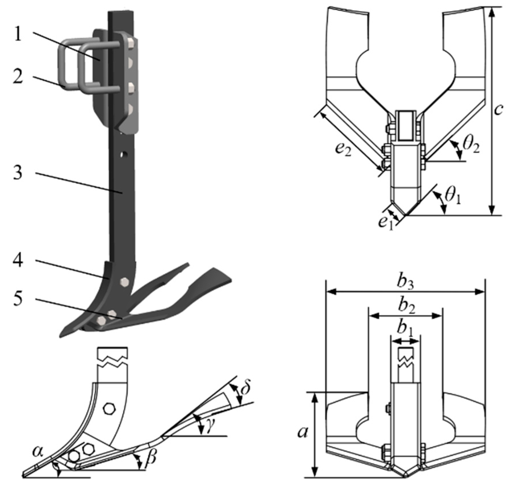
2.2.2. Force Analysis of In Situ Soil-Lifting Shovel
The force analysis of the in situ soil-lifting shovel is mainly subjected to the force of the shovel tip and the soil-lifting plate during soil lifting and straw deep-burying operations. The following is an analysis of the force exerted by the inclination of the in situ soil-lifting shovel when the soil plate is tilted outward.
During the operation process of the in situ soil-lifting shovel, the shovel tip is mainly subjected to the horizontal traction force of the in situ soil-lifting shovel, the pressure of the soil at the bottom of the ditch on the shovel tip, and its gravity [
19,
20,
21]. The stress situation is shown in
Figure 5.
Through force analysis, the force balance equation in the horizontal direction of the shovel tip of the in situ soil-lifting shovel is:
where
Fx1 is the horizontal traction force exerted on the tip of the in situ soil-lifting shovel (N);
N1 is the positive pressure applied to the normal direction of the shovel tip of the in situ soil-lifting shovel (N);
F1 is the frictional force acting on the tip of the in situ soil-lifting shovel (N);
b1 is the width of the shovel tip of the in situ soil-lifting shovel (mm);
α is the angle at which the tip of the in situ soil-lifting shovel enters the soil (°);
k is the pure cutting resistance of soil per unit width (N/mm);
The force balance equation for the tip of the in situ soil-lifting shovel in the vertical direction is:
where
μ1 is the friction coefficient between the soil and the tip of the in situ soil-lifting shovel;
G1 is the self-gravity of the tip of the in situ soil-lifting shovel (N).
The pure cutting resistance of soil is relatively small and can be ignored. Substituting Formulas (2) and (3) into Formula (1) yields:
From Equation (4), it can be seen that the angle of penetration
α there significantly impacts the resistance of the in situ soil-lifting shovel, mainly affecting its penetration performance and forward resistance. As the angle of penetration
α increases, the penetration ability deteriorates, and the resistance increases. The angle of penetration
α decreases, and the effect of loose soil lifting is poor. Based on the physical characteristics of the soil when returning straw to the field, and in combination with the design of the deep loosening shovel angle in the agricultural machinery design manual, determines the in situ soil-lifting shovel tip angle into the soil
α 25° [
22].
- 2.
Analysis of the force on the lifting plate of the in situ soil-lifting shovel
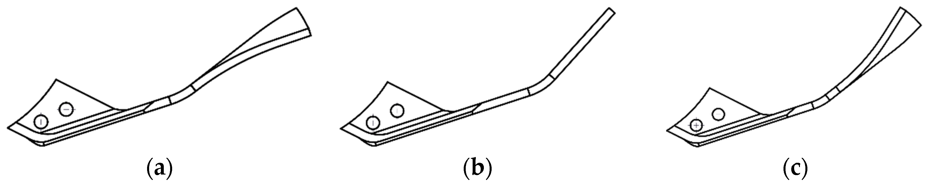
The lifting plate of the in situ soil-lifting shovel is an essential factor affecting the deep burial effect of straw and the operation resistance. To explore the optimal parameters of the lifting plate structure of the in situ soil-lifting shovel, a mechanical contact model between the lifting plate and the soil is established, and the stress analysis of the lifting plate is carried out. As shown in
Figure 6, the process of the soil-lifting shovel’s lifting plate is mainly divided into three stages, namely the (I) stage of oblique cutting of soil in the front section of the soil plate and lifting of soil; in the (II) stage, the middle section of the soil-lifting plate further lifts the soil and separates the soil; in the (III) stage, the soil is lifted and separated from the soil after the soil plate is lifted, completing the natural fall of the soil.
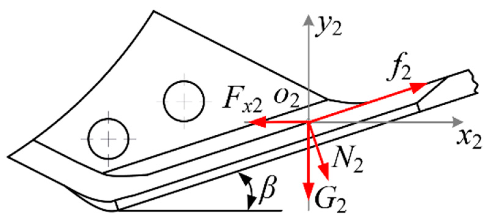
Establish a Cartesian coordinate system
o2x2y2 at any point on the surface of the front and middle sections of the lifting plate, with the
x2 axis indicating the forward direction of the lifting plate during operation and the
y2 axis indicating the vertical direction. Analyze the stress situation of the lifting plate when it comes into contact with soil particles in the (I) stage, including the soil support force
N2, soil friction force
f2, and its gravity
G2. The combined force acting on the lifting plate is the forward resistance
Fx2 of the lifting plate [
23]. As shown in
Figure 7, the force balance equation for the (I) stage is:
where
Fx2 is the horizontal traction force applied to the lifting plate in the (I) stage (N);
N2 is the positive pressure applied to the normal direction of the lifting plate (N);
f2 is the frictional force acting on the lifting plate (N);
β is the lifting angle of the soil plate (°);
μ2 is the friction coefficient between the soil and the lifting plate;
G2 is the gravity of the lifting plate itself (N).
Substituting Equations (6) and (7) into Equation (5) yields:
The force acting on the soil plate in the (II) stage is similar to that in the (I) stage. Similarly, it can be concluded that the force equation in the (II) stage is:
where
Fx3 is the horizontal traction force applied to the lifting plate in the (II) stage (N);
γ is the soil-lifting angle of the soil plate (°).
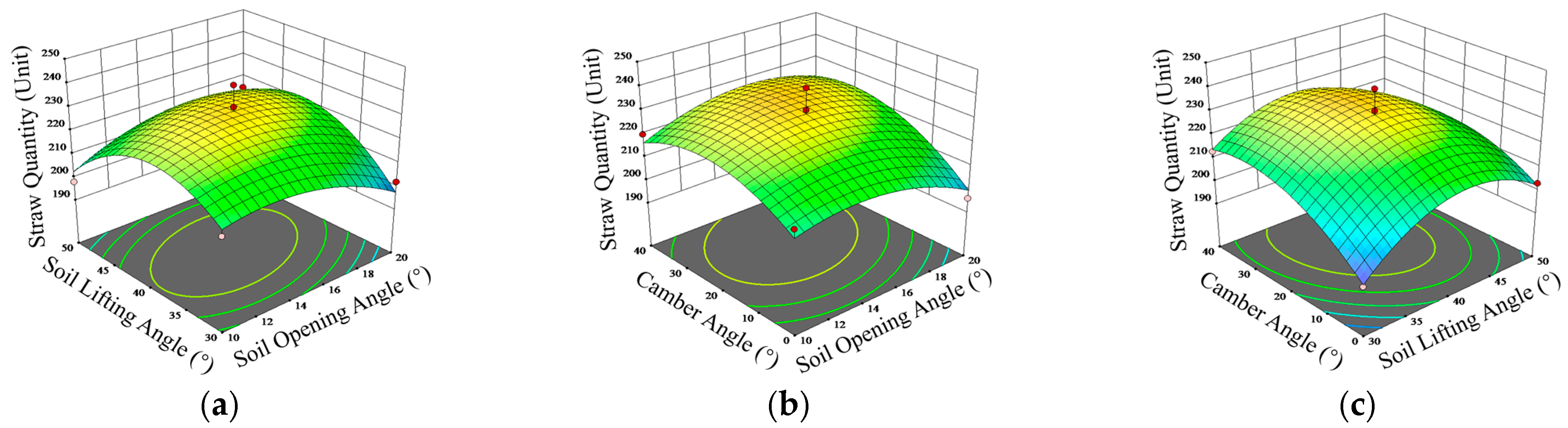
From Equations (8) and (9), it can be seen that the forward resistance Fx2 and Fx3 of the soil-lifting plate in stages (I) and (II) are related to the soil-opening angle β, soil-lifting angle γ. When increasing, the traction force increases regarding soil-opening angle β and soil-lifting angle γ. After too little, the effect of raising the soil cannot be achieved. Based on the relevant knowledge of the Agricultural Machinery Design Manual, determine the soil-opening angle β where the range of values is 10° to 20°, determining the soil-lifting angle γ where the value range is 30° to 50°. The following text will explore its optimal parameter combination through EDEM simulation experiments.
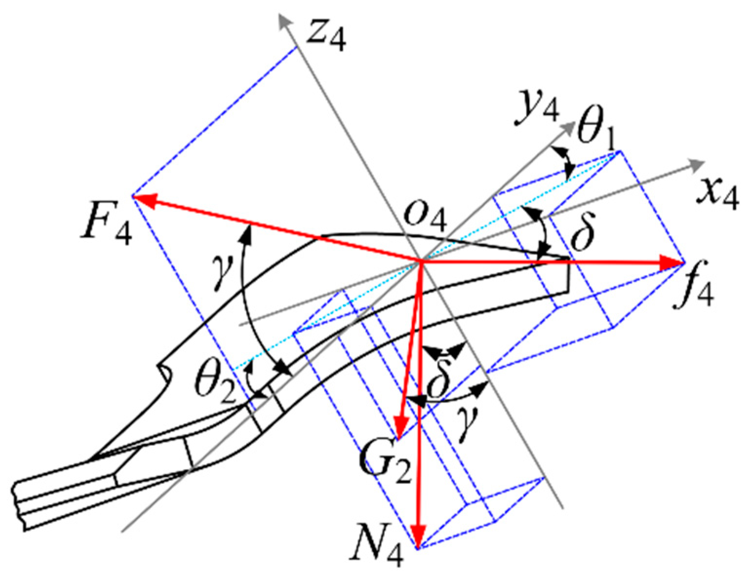
The force on the lifting plate of the in situ soil-lifting shovel in the (III) stage is shown in
Figure 8. At any point on the surface of the lifting plate in the (III) stage, a spatial Cartesian coordinate system
o4x4y4z4 is established, with the direction perpendicular to the forward direction as the
x4 axis, the direction tangential to the (II) stage working surface as the
y4 axis, and the direction perpendicular to the (II) stage working surface as the
z4 axis. Analyze the stress situation of the soil-lifting plate when it comes into contact with soil particles in the third stage, including the positive pressure
N4 on the lifting plate, which is perpendicular to the inclined plane. The horizontal traction force
F4 in the forward direction is along the direction of the implement’s forward movement. The direction of friction force
f4 at
o4 is the flow direction of soil particles at
o4. The self-gravity
G2 is perpendicular to the forward direction and downward. According to the analysis, the equilibrium equations for the
x4,
y4, and
z4 axes are:
where
F4 is the horizontal traction force on the soil-lifting plate in the (III) stage (N);
N4 is the positive pressure applied to the normal direction of the lifting plate (N);
f4 is the frictional force acting on the lifting plate (N);
δ is the camber angle of the soil-lifting plate (°);
θ1 is the angle between the projection of frictional force
f4 in the
o4x4y4 plane and the
y4 axis (°);
θ2 is the angle between the projection of positive pressure
N4 in the
o4x4y4 plane and the
y4 axis (°).
Angle
θ1 is related to the direction of soil flow at point
o4. The direction of positive pressure
N4 is fixed, so
θ2 the angle is fixed and constant. By combining Formulas (10)–(13), it can be concluded that the forward direction traction force
F4 is:
According to Formulas (14) and (15), it can be seen that the horizontal traction force in the forward direction is related to the soil-lifting angle of the in situ soil-lifting shovel’s lifting plate γ, regarding camber angle δ.
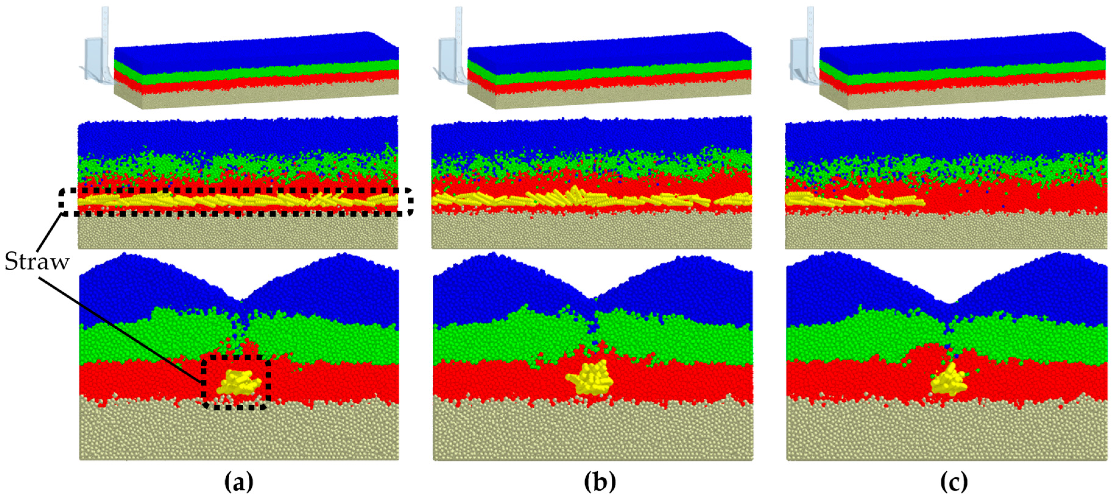
To determine the camber angle
δ value range for different camber angle angles
δ, three types of in situ soil-lifting shovels were designed for single-factor simulation pre-testing, as shown in
Figure 9.
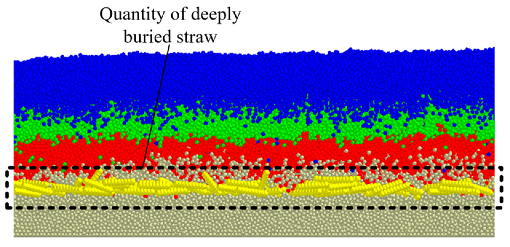
Figure 9 shows that under the three types of in situ soil-lifting shovels, the soil plow layer did not change. Regarding the depth of straw burial, the outward and normal conditions were better than the inward inclination conditions. Statistical analysis of the amount of deeply buried straw and operational resistance data under different shovel types are shown in
Figure 10 and
Figure 11.
The analysis shows that the depth of straw burial under outward inclination and the non-inclined shovel type is stable over time. After 1.1 s, the straw cannot be deeply buried under the inward inclined shovel type. Under the three shovel conditions, the pressure exerted by the in situ soil-lifting shovel is not significantly different. In contrast, the operating resistance is more significant under inward-inclined conditions than that under outward-inclined and non-inclined conditions. Analysis shows that under inward-inclined conditions, the soil aggregation effect is better, which hinders the transportation of straw and affects the downward transport of straw in the straw-conveying duct. The inward incline of the soil plate is compressed by the soil, resulting in more excellent resistance. Based on the above analysis, under the condition of inward inclination, the effect of straw deep burial is not good. Under non-inclined conditions, the effect of straw burial is not much different from that of outward inclination, so the camber angle δ is set and the range is 0° to 40°.


 ,
, 


