Article

Research on Differential Steering Dynamics Control of Four-Wheel Independent Drive Electric Tractor

1
College of Engineering, Nanjing Agricultural University, Nanjing 210031, China
2
State Key Laboratory of Intelligent Agricultural Power Equipment, Luoyang 470139, China
3
College of Emergency Management, Nanjing Tech University, Nanjing 210009, China
*
Authors to whom correspondence should be addressed.
Agriculture 2023, 13(9), 1758; https://doi.org/10.3390/agriculture13091758
Submission received: 5 August 2023 / Revised: 31 August 2023 / Accepted: 2 September 2023 / Published: 4 September 2023
(This article belongs to the Special Issue Agricultural Machinery Design and Agricultural Engineering)

Abstract

:
Traditional tractors can only achieve steering through mechanical structures such as steering knuckles and steering trapezoids. Among them, the mechanical structure is more complex, and various parts are easily damaged, making the tractor malfunction. The four-wheel independent drive differential steering mode differs from the traditional Ackermann steering mode, which realizes steering by controlling the inner and outer wheel torque, which can accurately steer the working state of high-end agricultural machinery equipment and improve the operating efficiency of agricultural machinery equipment. Aiming at the dynamic control problem in the steering of electric tractor four-wheel independent drive, a layered control strategy based on the sliding mode control of yaw torque at the upper level and the optimal torque distribution level based on the mean load rate of vehicle tires at the lower was proposed. By analyzing the differential steering mechanism of a four-wheel independent drive, a dynamic model of differential steering of the electric tractor is established, and a dynamic controller of a four-wheel independent drive is designed according to the layered control strategy. The upper controller tracks and controls the expected yaw speed on the basis of the sliding mode control to track the driver’s intention, and the lower controller realizes the optimal torque distribution based on the principle of the optimal average load rate of the vehicle tire to ensure the steering stability of the electric tractor. The effect of the controller was simulated and analyzed under typical conditions of double line shift, serpentine, and step. The results showed that the sliding mode controller is better than the PID controller in driver intention tracking. Compared with the average allocation strategy, the average maximum load rate of the vehicle tire under the three working conditions is reduced by 16.9%, 13.8%, and 17.3%, respectively, which proves the effectiveness of the layered control strategy. In the real car test, the sliding mode controller is better than the PID controller in the driver intention tracking. This study has important guiding significance for improving the maneuverability and stability of electric tractors.

1. Introduction

Electric tractors have the advantages of zero emissions, low noise, and high efficiency [1,2,3]. The four-wheel independent drive electric tractor abandons the traditional half-shaft, universal joint, differential, and other transmission components. It uses the reducer to connect the motor with each driving wheel directly. By controlling the difference between the driving or braking forces of the two sides of the wheel, the wheel speed difference is generated, so as to achieve the steering function [4,5]. However, the four-wheel independent drive electric tractor needs to design a controller based on the vehicle dynamic model to ensure steering control and driving stability; otherwise, it is prone to instability when driving on complex road surfaces [6]. The dynamic controller’s control output is generally the wheel motor’s torque. The dynamic model of the electric tractor is the basis of the torque control of the electric tractor; hence, it is necessary to establish an accurate electric tractor model.
The wheeled differential steering tractor differs from the traditional Ackermann steering tractor because it has no steering mechanism and can realize in situ steering; hence, its dynamics modeling has become a research focus. Maclaurin et al. [7,8,9] compared differential steering and the Ackermann steering model and analyzed the basic performance of differential steering vehicles. The results showed an oversteer in differential steering vehicles but an understeer in Ackermann steering vehicles. Yu et al. [10] established a differential steering dynamic model considering the rolling friction coefficient between the tread and the ground and conducted experimental verification. Mokhiamar et al. [11] established a dynamic model of stable differential steering vehicle motion, extended the stability limit of differential steering vehicles, and significantly improved vehicle handling performance. The above dynamic modeling is aimed at ordinary cars, and there is little research on electric tractors. This paper presents modeling for electric tractors.
The research object of this paper is the four-wheel independent drive electric tractor. Each motor is independent and controllable; thus, it must involve the torque distribution of each motor. Du et al. [12] adopted an adaptive speed tracking controller, which can effectively avoid excessive slip under low friction conditions by automatically adjusting torque instructions. Ni et al. [13] designed a horizontal controller based on a robust output feedback method to ensure the horizontal and longitudinal stability of autonomous vehicles. However, the controller studied in this paper had insufficient adaptability to complex road surfaces. Shino et al. [14] proposed direct yaw torque control based on drive/brake force distribution, which improved vehicle controllability and stability. Nevertheless, the natural distribution torque distribution controller was unsuitable for complex road surfaces. Xu Dan et al. [15] proposed that the optimal objective function of system energy efficiency can improve the economic benefits of the vehicle. However, the optimal control of vehicle energy efficiency could lead to vehicle understeering. Li et al. [16] took the degree of motor failure as a constraint condition and distributed the torque of each wheel to ensure that the vehicle would not skid or roll. Yan et al. [17] took the maximum vehicle attachment margin as the optimization goal to achieve the driving force distribution of the six-wheel motor and reduce the risk of vehicle roll. Kang et al. [18] studied differential steering vehicles with six-wheel independent drive using layered control. The upper controller tracked the speed and yaw speed, while the lower controller directly controlled the tire force through the tire model. The above studies on differential steering vehicle dynamics control were all aimed at uncrewed vehicles, which directly track the reference path given by the upper level and convert the vehicle longitudinal demand speed and steering demand difference into torque for control. This control method does not apply to crewed vehicles.
To sum up, aiming at the problems existing in the current research, this paper studies the differential steering dynamic control of a four-wheel independent drive electric tractor, and its primary contributions are outlined below.
To improve the accuracy of the whole dynamic model of the tractor, this paper introduces the tire force model and establishes the whole dynamic model of the tractor. According to the Ackermann steering model, the relationship between the steering wheel angle and the tractor longitudinal velocity difference ratio is established in the differential steering model. Aiming at the dynamic control effect of the tractor, the layered control strategy is designed. The upper level is designed with a sliding mode controller, which can track the desired yaw speed quickly and stably. In the lower layer, a torque distribution controller based on the mean load rate of the whole vehicle tire is proposed to improve the tractor’s stability. In this paper, various typical working conditions are simulated and tested on a real tractor, and the results verify the effectiveness of the proposed algorithm.

2. Materials and Methods

2.1. Establishment of Dynamic Model of Electric Tractor

2.1.1. Tire Force Model

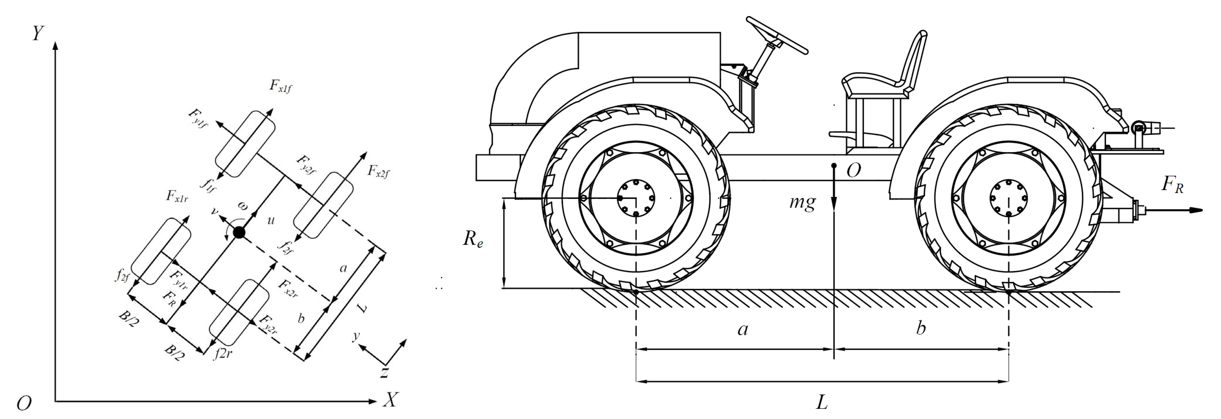
The tire is an essential part of the electric tractor in contact with the ground, and the analysis of tire force is vital [19]. The wheel speed analysis of the differential steering electric tractor is shown in Figure 1.
The following assumptions are made during the derivation of the model:
(1)
The longitudinal velocity at the center of gravity is constant;
(2)
When driving in a non-limiting state, the electric tractor is in a linear state, where it is assumed that the tire is in a linear region;
(3)
The electric tractor is driving on the horizontal road surface, and the center of gravity does not shift;
(4)
The air resistance faced by the vehicle at low speed is small and, thus, ignored in this paper.
In the presentation of this article, it is assumed that, when the electric tractor turns left, the left side is inside, the right side is the outside, the subscripts 1 and 2 respectively represent the left and right sides, the subscripts x and y respectively represent the longitudinal and transverse of the tire, and the subscripts f and r respectively represent the front and rear wheels. The longitudinal slip speed of the tire is expressed as
v s x = V x ω r R e
where v s x is the longitudinal slip speed of the tire (m/s), V x is the longitudinal speed of the center of the wheel (m/s), ω r is the angular speed of the wheel (rad/s), and R e is the rolling radius of the wheel (m).
The longitudinal speeds of the left and right wheel centers are as follows:
{ V x 1 = ω r R e B 2 ω V x 2 = ω r R e + B 2 ω
where V x 1 is the longitudinal speeds of the left wheel centers (m/s), V x 2 is the longitudinal speeds of the right wheel centers (m/s), B is the wheelbase (m), and ω is the yaw angle speed of the electric tractor (rad/s).
The angular velocity difference between the left wheel and the right wheel is
Δ ω r = ω r 2 ω r 1
where Δ ω r is the speed difference between the left and right wheels (rad/s), ω r 2 is the angular speed at the right wheel (rad/s), and ω r 1 is the angular speed at the left wheel (rad/s).
The angular speed of the left and right wheels is
{ ω r 1 = ω r 1 2 Δ ω r ω r 2 = ω r + 1 2 Δ ω r
The longitudinal slip speed of the wheels of an electric tractor can be expressed as
{ v s x 1 f = v s x 1 r = V x 1 ω r 1 R e = ω r R e B 2 ω ( ω r 1 2 Δ ω r ) R e = 1 2 Δ ω r R e B 2 ω v s x 2 f = v s x 2 r = V x 2 ω r 2 R e = ω r R e + B 2 ω ( ω r + 1 2 Δ ω r ) R e = ( 1 2 Δ ω r R e B 2 ω )
where v s x 1 f , v s x 1 r , v s x 2 f , and v s x 2 r are the longitudinal slip velocities of the left front, left back, right front, and right back, respectively (m/s).
The lateral slip velocity [20] can be expressed as
{ v s y 1 f = v s y 2 f = v + a ω v s y 1 r = v s y 2 r = v b ω
where v s y 1 f , v s y 1 r , v s y 2 f , and v s y 2 r are the lateral slip velocity of the left front, left back, right front, and right back, respectively (m/s), a is the distance from the center of gravity of the electric tractor to the front axle (m), b is the distance from the center of gravity of the electric tractor to the rear axle (m), u is the longitudinal speed at the center of mass of the electric tractor (m/s), and v is the transverse speed at the center of mass of the electric tractor (m/s); u = ω r R e and Δ u = Δ ω r R e .
Formula (5) can be expressed as
{ v s x 1 f = v s x 1 r = 1 2 Δ u B 2 ω v s x 2 f = v s x 2 r = ( 1 2 Δ u B 2 ω )
The longitudinal slip rate and side deflection angle of a tire [21] can be expressed as
{ S x 1 f = v s x 1 f ω r 1 R e ,   S x 2 f = v s x 2 f ω r 2 R e ,   S x 1 r = v s x 1 r ω r 1 R e ,   S x 2 r = v s x 2 r ω r 2 R e α 1 f = v s y 1 f ω r 1 R e ,   α 2 f = v s y 2 f ω r 2 R e ,   α 1 r = v s y 1 r ω r 1 R e ,   α 2 r = v s y 2 r ω r 2 R e
where S x 1 f , S x 2 f , S x 1 r , and S x 2 r are the longitudinal slip ratio of the left front, right front, left back, and right back, respectively, while α 1 f , α 2 f , α 1 r , and α 2 r , are the angle of lateral drift of left front, right front, left back, and right back, respectively (rad).
The tire is a part that is directly in contact with the road when the electric tractor is running, and there is a slide relative to the ground when running. The tire’s slip rate and slip angle can estimate the friction force on the tire. The friction generated when a tire slides is constant and can be broken down into transverse and longitudinal. The two components of tire force in this paper can be regarded as approximately independent parts. When the road adhesion coefficient is large, the linear range of tire sideward characteristics also becomes larger. When the electric tractor is running in a non-limit state, the tire is in a linear state; thus, this paper assumes that the tire is in a linear region. The longitudinal and transverse forces can be expressed as
{ F x = k x S x F y = k α α
where F x is the longitudinal force (N), F y is the transverse force (N) k x is the longitudinal glide stiffness of the tire e (N), and k α is the lateral stiffness of the tire e (N/rad).
Consider that coaxial tires have the same longitudinal slip stiffness and lateral stiffness.
{ k x f = k x 1 f = k x 2 f ,   k x r = k x 1 r = k x 2 r k α f = k α 1 f = k α 2 f ,   k α r = k α 1 r = k α 2 r
where k x 1 f , k x 2 f , k x 1 r , and k x 2 r are the longitudinal sliding stiffness of the left front, right front, left back, and right back, respectively, k α 1 f , k α 2 f , k α 1 r , k α 2 r are the lateral stiffness of the left front, right front, left back, and right back, respectively (rad), k x f and k x r are the front and rear axle longitudinal stiffness (N), and k α f and k α r are the rear axle and rear axle longitudinal stiffness (N/rad).
Formulas (5)–(10) can be used to derive Formula (11), where the longitudinal and transverse forces of each wheel can be expressed as
{ F x 1 f = 1 u 1 2 Δ u ( 1 2 Δ u B 2 ω ) k x f ,   F x 2 f = 1 u + 1 2 Δ u ( 1 2 Δ u B 2 ω ) k x f F x 1 r = 1 u 1 2 Δ u ( 1 2 Δ u B 2 ω ) k x r ,   F x 2 r = 1 u + 1 2 Δ u ( 1 2 Δ u B 2 ω ) k x r F y 1 f = 1 u 1 2 Δ u ( v + a ω ) k α f ,   F y 2 f = 1 u + 1 2 Δ u ( v + a ω ) k α f F y 1 r = 1 u 1 2 Δ u ( v b ω ) k α r ,   F y 2 r = 1 u + 1 2 Δ u ( v b ω ) k α r
where F x 1 f , F x 2 f , F x 1 r , and F x 2 r are the longitudinal forces of the left front, right front, left back, and right back, respectively (N), and F y 1 f , F y 2 f , F y 1 r , and F y 2 r are the transverse forces of the left front, right front, left back, and right back, respectively (N).

2.1.2. Body Dynamics Model

In the process of steering movement, the force and torque of the electric tractor are shown in Figure 2.
According to Newton’s second law,
{ m a x = F x 1 f + F x 2 f + F x 1 r + F x 2 r F R f 1 f f 2 f f 1 r f 2 r m a y = F y 1 f + F y 2 f + F y 1 r + F y 2 r I z ω · = B 2 ( F x 1 f + F x 2 f F x 1 r + F x 2 r + f 1 f + f 1 r f 2 f f 2 r ) + a ( F y 1 f + F y 2 f ) b ( F y 1 r + F y 2 r )
where a x is lateral acceleration ( a x = u · v ω ) (m/s2), a y is longitudinal acceleration ( a y = v · + u ω ) (m/s2), ω · is the yaw angle acceleration (rad/s2), I z is the moment of inertia about the z-axis (kgm2), m is the mass of the electric tractor (kg), F R is the drag resistance of an electric tractor (N), and f 1 f , f 2 f , f 1 r , and f 2 r are the rolling resistance of the left front, right front, left back, and right back, respectively (N).
Assume that each wheel has the same rolling resistance. Combined with Formula (11), the kinetic differential equation of the above equation can be written as
{ m ( v · + u ω ) = 1 1 ( 1 2 Δ u u ) 2 2 u [ ( a k α f b k α r ) ω + ( k α f + k α r ) v ] I z ω · = 1 1 ( 1 2 Δ u u ) 2 1 u { [ B 2 2 ( k x f + k x r ) + 2 ( a 2 k α f + b 2 k α r ) ] ω 2 ( a k α f b k α r ) v + B 2 ( k x f + k x r ) Δ u }
When the differential rate of change of velocity Δ u u is small, the infinitesimal of higher order can be ignored [22]; then, it can be obtained that
{ m ( v · + u ω ) = 2 u ( a k α f b k α r ) ω 2 u ( k α f + k α r ) v I z ω · = 1 u [ B 2 2 ( k x f + k x r ) + 2 ( a 2 k α f + b 2 k α r ) ] ω 2 u ( a k α f b k α r ) v + B 2 ( k x f + k x r ) Δ u u
When v · = 0 and ω · = 0 , according to the above formula, the steady state ω can be obtained, and the specific expression is as follows:
ω = B ( k x f + k x r ) ( k α f + k α r ) Δ u 4 L 2 k α f k α r + B 2 ( k x f + k x r ) ( k α f + k α r ) + 2 ( b k α r a k α f ) m u 2
where L is the wheelbase (m).
The steady yaw velocity gain is expressed as follows:
ω Δ u / u = B ( k x f + k x r ) ( k α f + k α r ) u 4 L 2 k α f k α r + B 2 ( k x f + k x r ) ( k α f + k α r ) + 2 ( b k α r a k α f ) m u 2
Since the parameters in (16) are all constants, it can be written as
ω Δ u / u = A u C + D u 2 = A / C 1 + D / C u 2 u
where A = B ( k x f + k x r ) ( k α f + k α r ) , C = 4 L 2 k α f k α r + B 2 ( k x f + k x r ) ( k α f + k α r ) , and D = 2 ( b k α r a k α f ) m .

2.2. Driver Intention Recognition

For electric tractors, the controller often receives the speed and angular speed instructions transmitted from the upper decision-making planning module and then converts them into the wheel torque on both sides for control. Ignoring the sliding of the wheel, it is assumed that the difference rate between the steering wheel angle and the longitudinal speed of the wheel is linear [23]. When the steering wheel angle is stable, it is assumed that it conforms to the following relation:
k s δ ( t ) = Δ u u
where k is a constant, which can be determined according to the minimum steering radius of the electric tractor and the maximum steering wheel angle, and δ ( t ) is the steering wheel angle.
The steady yaw velocity gain calculated on the basis of the Ackermann two-degree-of-freedom monorail model [24] for steering vehicles is
ω δ = V x / L 1 + K V x 2
where δ is the front wheel angle, and K is the stability factor ( K = m L 2 ( a k α r b k α f ) ).
By comparing Formula (19) and substituting Formula (18) into (16), the steady yaw angular velocity gain can be solved as follows:
ω Δ u / u = A C u = B ( k x f + k x r ) ( k α f + k α r ) 4 L 2 k α f k α r + B 2 ( k x f + k x r ) ( k α f + k α r ) u
Therefore, the yaw velocity of the differential steering electric tractor during steady neutral steering is
ω = k s δ ( t ) B ( k x f + k x r ) ( k α f + k α r ) 4 L 2 k α f k α r + B 2 ( k x f + k x r ) ( k α f + k α r ) u

2.3. Layered Control Strategy for Differential Steering of Electric Tractor

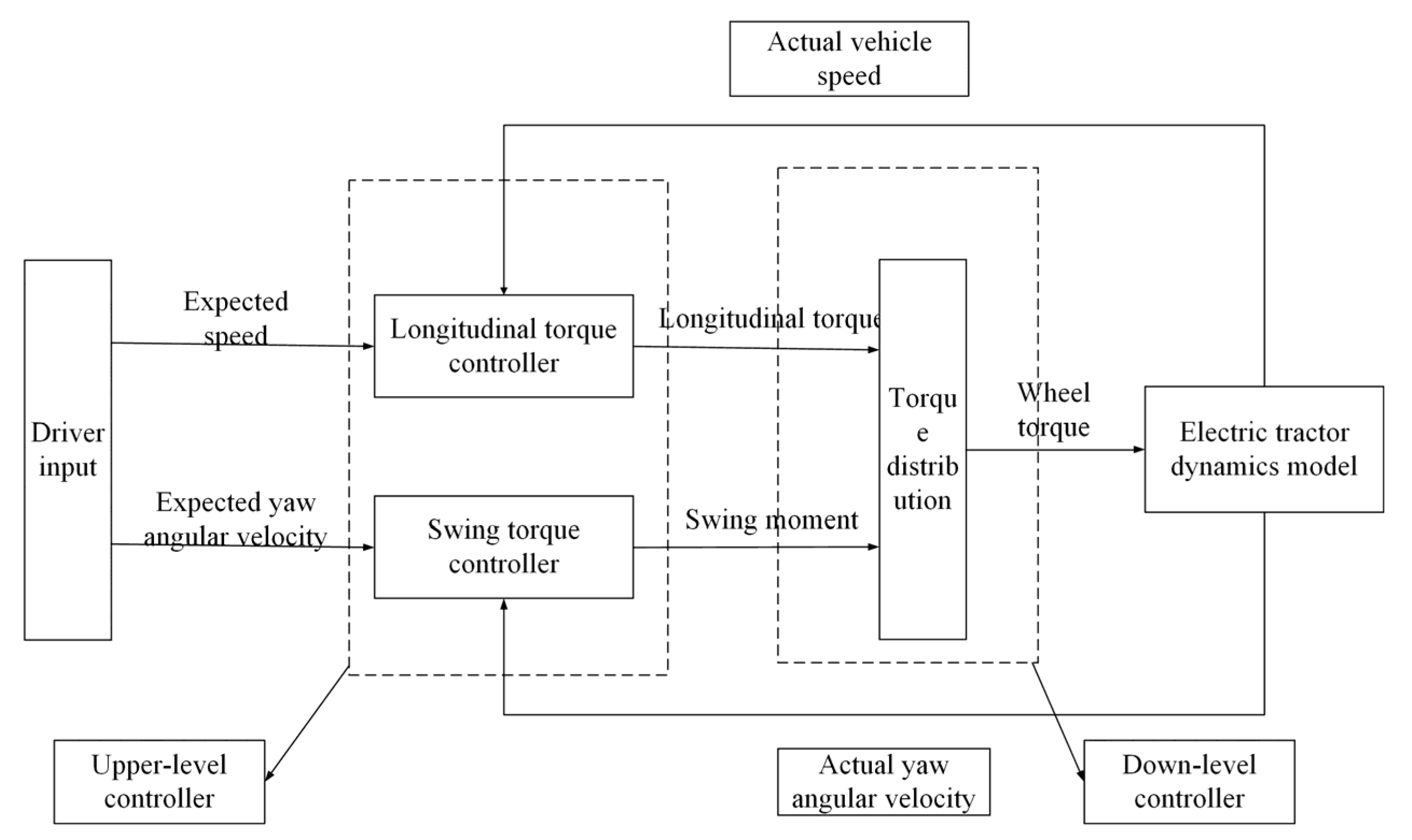
The overall control strategy of this paper is shown in Figure 3, which is divided into two modules. The upper level includes two controllers, the longitudinal moment controller and the yaw moment controller, to ensure that the electric tractor tracks the desired yaw angle speed. The lower layer is the torque distribution controller, which distributes the longitudinal driving moment and yaw moment obtained from the upper level to the four wheels in the optimal distribution way of the mean load rate of the vehicle tire, ensuring the lateral stability of the electric tractor and avoiding the phenomenon of side slide.
In the longitudinal torque controller, the PID algorithm is used to ensure the fast-tracking of longitudinal speed, collect the pedal voltage simulation of the driver’s operation of the electric tractor, convert it into the target expected longitudinal speed of the electric tractor, and obtain the actual longitudinal speed according to the speed sensor. The PID controller’s longitudinal torque of the electric tractor output is calculated.
In the expected yaw moment controller, a sliding mode control algorithm is used to collect the simulated voltage of the driver’s steering wheel of the electric tractor and convert it into the expected yaw angle speed. The actual yaw angle speed is obtained according to the gyroscope, and the electric tractor’s expected and actual yaw angle speed is input to the yaw moment controller to determine the yaw moment. In the design of an electric tractor, the tire load rate is a crucial design index. When driving on the road, the smaller the tire load rate, the more adhesion margin the tire will have to be allocated to the transverse forces to improve the lateral stability of the tractor [25,26] to ensure that the tractor does not slip and roll. In the torque distribution controller, this paper takes the average load rate of the whole vehicle tire as the optimization goal. It optimally distributes the control torque obtained from the upper level to the four wheels.

2.3.1. Upper-Level Yaw Moment Setting Controller

According to the steering angle command issued by the steering wheel angle, the electric tractor controls the yaw moment of the electric tractor to realize the tracking control of the driver’s intention. Adding the desired yaw moment to Equation (14), it becomes
{ m ( v · + u ω ) = 2 u ( a k α f b k α r ) ω 2 u ( k α f + k α r ) v I z ω · = 1 u [ B 2 2 ( k x f + k x r ) + 2 ( a 2 k α f + b 2 k α r ) ] ω 2 u ( a k α f b k α r ) v + B 2 ( k x f + k x r ) Δ u u + M z
where M z is the yaw moment (Nm).
The yaw velocity tracking deviation and the derivative of the deviation are defined as
{ e z = ω ω z _ exp e · z = ω · ω · z _ exp
where e z is the yaw velocity tracking deviation, e · z is the derivative of the deviation, and ω · z _ exp is the yaw angle velocity of steady-state steering solved by Formula (20) (rad/s).
The sliding surface is defined as
s = c e z + e · z
where c is the relative weight coefficient between the deviation and the deviation change rate, which is greater than 0.
s · = c e · z + e · · z = c e · z + ω · · ω · · z _ exp
The buffeting caused by the discontinuity of the function can be effectively reduced using the isokinetic approach law [27].
s · = ε sgn ( s ) k s ,   ε > 0 ,   k > 0
Formulas (23)–(26) are substituted into Formula (22) to obtain Formula (27). The calculation formula to determine the yaw moment is
M z = { ( ε sgn s k s c e · z + ω z _ exp ) I z + B 2 ( k x f + k x r ) + 2 ( a 2 k α f + b 2 k α r ) 2 u ω · 2 ( a k α f b k α r ) u [ 2 m u ( a k α f b k α r ) ω + u ω + 2 u ( k α f + k α r ) v ] + B 2 ( k x f + k x r ) k s δ ( t ) · } d t
According to the stability theory (Lyapunov), the reachability expression is
{ V ( x ) = 1 2 s 2 V · ( x ) = s s ·
Combining the above formulas yields
V · ( x ) = s s · = s ( ε sgn ( s ) k s ) ε | s | k s 2 k V ( x ) 2
The system is judged to be stable according to the reachability condition.

2.3.2. Lower-Level Torque Distribution Controller

The electric tractor is designed to generate torque from four hub motors, which distribute torque to each wheel through a reducer. Limited by the motor’s power and the maximum adhesion of each tire, the relevant constraints must be set. To improve the efficiency of calculation, the influence of tire transverse forces on the yaw moment of the whole machine is ignored in the analysis process.
The rolling resistance is small when the electric tractor is driving on the road surface with a good adhesion coefficient. Without considering the influence of rolling resistance, it can be obtained that the sum of the driving torque of four tires is equal to the longitudinal torque obtained using the PID controller when the road surface adhesion limit force is less than that. The yaw moment produced by the longitudinal force of the tire is equal to the expected yaw moment obtained by the sliding mode controller. According to the constraint conditions determined by the road adhesion limit, the driving torque distributed by each wheel motor cannot exceed the limit driving torque, and the constraint conditions can be obtained in summary.
{ T 1 f + T 2 f + T 1 r + T 2 r = T d B 2 R e ( T 1 f T 2 f + T 1 r T 2 r ) = M z T i j min ( μ F x i j R e ,   T max )
where T i j (i = 1, 2, j = f, r) is the driving torque of each wheel (Nm), T d is the total driving torque of the whole machine (Nm), μ is the adhesion coefficient between the tire and the ground, and T max is the maximum driving torque provided by the motor through the maximum torque converted by the reducer (Nm).
The force between the tire and the ground is the core factor influencing the electric tractor’s stability. When the tire’s adhesion exceeds the ground’s adhesion limit, the tire will become unstable and slip.
This paper takes the minimum tire load rate as the optimization goal and optimizes the distribution of the yaw moment. The tire load rate is expressed as
η i j = F x i j 2 + F y i j 2 μ i j F z i j
where η i j is the tire load rate, F x i j is the Longitudinal force for each tire (N), F y i j is each tire’s transverse forces (N), F z i j is each tire’s vertical force (N), and μ i j is the adhesion coefficient between the tire and the ground.
A reasonable distribution of yaw control moment allows keeping the electric tractor stable. This means that, when turning, enough transverse forces need to be allocated to the required wheels to maintain the stability and handling of the electric tractor. The optimal distribution of tire load rate can be achieved by optimizing the torque distribution on the four wheels. By precisely distributing torque, the load on each wheel can be balanced, reducing the overall load rate and improving the stability of the electric tractor. By optimizing the distribution of tire load rate, each tire’s load can be balanced, and the overload of a certain tire can be avoided. This not only helps to improve the stability of the electric tractor but also extends the service life of the tires [28].
The average tire load rate can be used as a measure of vehicle stability. When the tire load rate is low, the steering stability of the electric tractor can be improved. When the tire load rate is high, it means that the tire attachment capacity reaches the upper limit, which easily leads to the instability of the electric tractor. Therefore, the average load rate of vehicle tire is taken as the optimization objective of this paper, and the objective function is as follows:
J = 1 4 ( F x 1 f 2 + F y 1 f 2 μ 1 f 2 F z 1 f 2 + F x 1 r 2 + F y 1 r 2 μ 1 r 2 F z 1 r 2 + F x 2 f 2 + F y 2 f 2 μ 2 f 2 F z 2 f 2 + F x 2 r 2 + F y 2 r 2 μ 2 r 2 F z 2 r 2 )
where J is the mean function of the vehicle tire load rate.
In this paper, only longitudinal forces are considered, and the optimization objective function is simplified and expressed by torque.
min J = 1 4 ( F x 1 f 2 μ 1 f 2 F z 1 f 2 + F x 1 r 2 μ 1 r 2 F z 1 r 2 + F x 2 f 2 μ 2 f 2 F z 2 f 2 + F x 2 r 2 μ 2 r 2 F z 2 r 2 ) = 1 4 ( T x 1 f 2 μ 1 f 2 F z 1 f 2 R e 2 + T x 1 r 2 μ 1 r 2 F z 1 r 2 R e 2 + T x 2 f 2 μ 2 f 2 F z 2 f 2 R e 2 + T x 2 r 2 μ 2 r 2 F z 2 r 2 R e 2 )
In this paper, because only two equality constraints and four independent variables are involved, the minimum method is chosen as the solution method. However, to meet the real-time requirements, we can simplify the calculation process and improve the efficiency by substituting the equality constraint into the objective function.
{ T 1 f = T d 2 M z R e B T 1 r T 2 f = T d 2 + M z R e B T 2 r
Introducing Formula (32) into (31) yields
J = 1 4 [ ( T d 2 M z B R e T 1 r ) 2 μ 1 f 2 F z 1 f 2 R e 2 + ( T d 2 + M z B R e T 2 r ) 2 μ 2 f 2 F z 2 f 2 R e 2 + T 1 r 2 μ 1 r 2 F z 1 r 2 R e 2 + T 2 r 2 μ 2 r 2 F z 2 r 2 R e 2 ]
Since the objective function has only two independent variables, the extreme value method takes the partial derivative of T 1 f and T 2 f . When the second derivative is calculated, the second derivative is greater than 0; thus, the extreme value is taken at the point where the first derivative is equal to 0. If we set the first derivative to 0, we can figure out the torque of each wheel.
{ T 1 f = ( T d 2 M z B R e ) μ 1 f 2 F z 1 f 2 μ 1 f 2 F z 1 f 2 + μ 1 r 2 F z 1 r 2 ,   T 1 r = ( T d 2 M z B R e ) μ 1 r 2 F z 1 r 2 μ 1 f 2 F z 1 f 2 + μ 1 r 2 F 1 r 2 T 2 f = ( T d 2 + M z B R e ) μ 2 f 2 F z 2 f 2 μ 2 f 2 F z 2 f 2 + μ 2 r 2 F z 2 r 2 ,   T 2 r = ( T d 2 + M z B R e ) μ 2 r 2 F 2 r 2 μ 2 f 2 F z 2 f 2 + μ 2 r 2 F 2 r 2

2.4. Real Electric Tractor

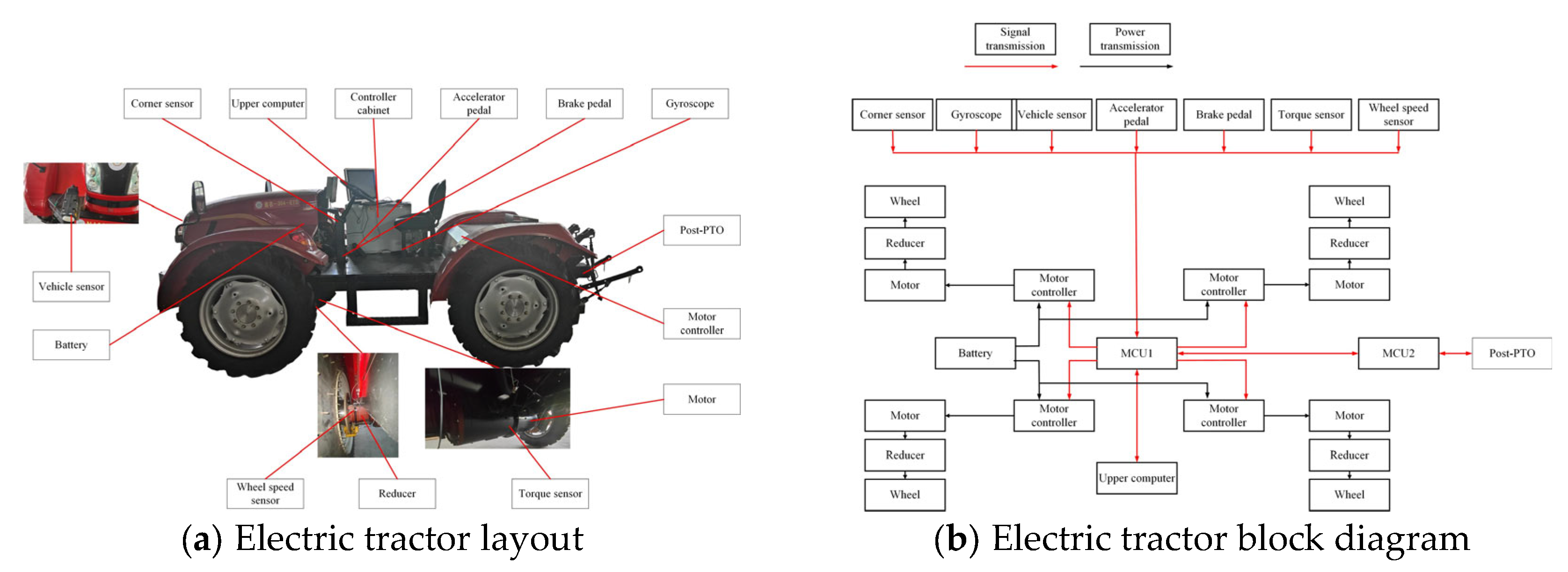
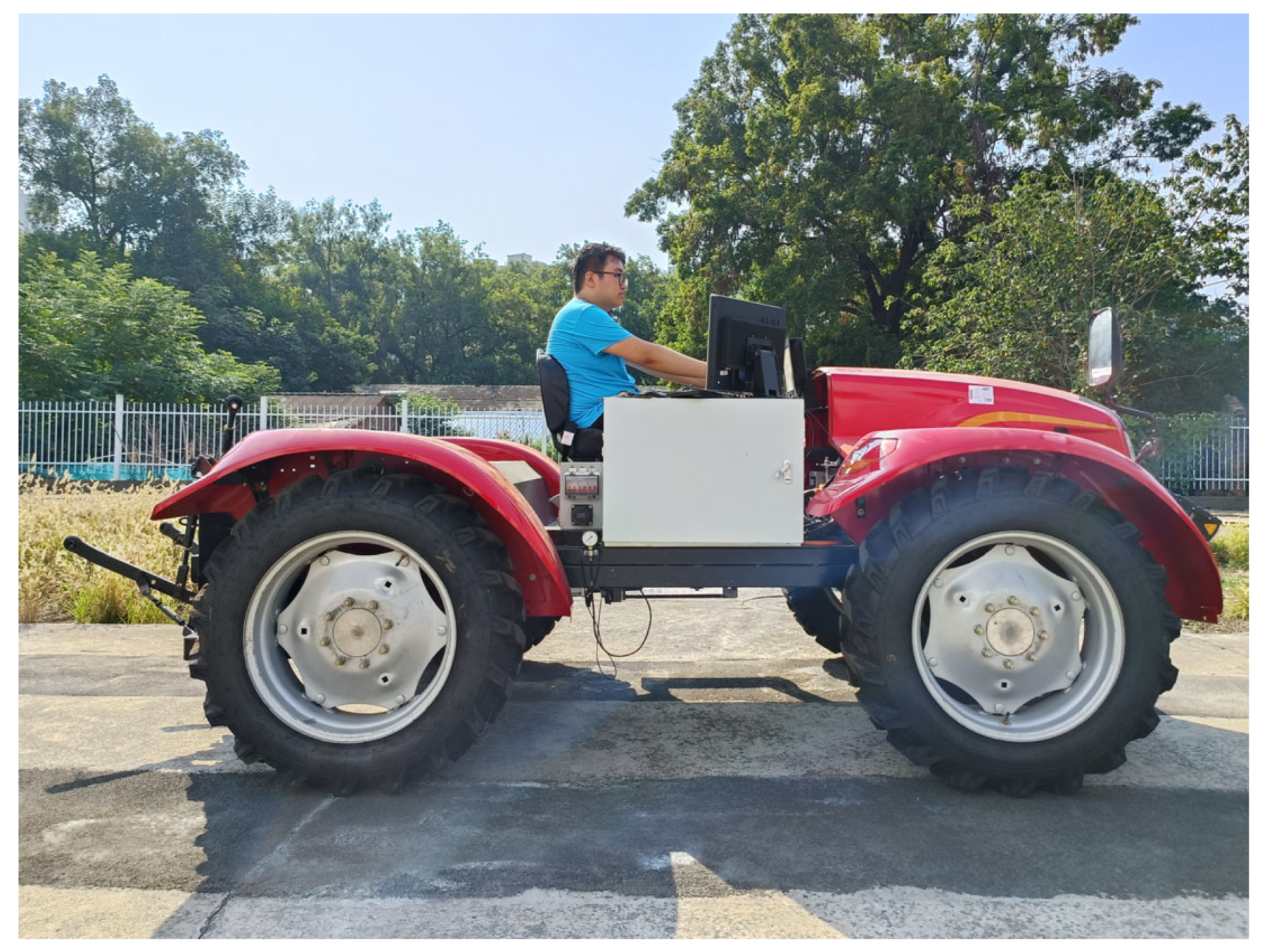
This paper studies a four-wheel independent drive electric tractor and its system structure assembly, as shown in Figure 4. The main components are a power battery, wheel hub motor, wheel reducer, motor controller, three-point suspension device, and PTO. The hub motor is directly connected to the wheel reducer to provide the driving force for the tractor drive wheel. The battery communicates with the MCU1 controller through the CAN bus, and MCU1 directly controls the four motor controllers according to the driver’s signal. When the machine is in operation, MCU1 sends messages to MCU2 through the CAN bus according to the driver’s intention to realize rotary tillage and plowing operation.
The electric tractor is driven by a permanent magnet brushless DC motor; the motor model is a JY-200V/30A permanent magnet brushless DC motor, the rated torque is 100 N·m, and the speed range is 0~900 r/min. The structure of the wheel reducer is a planetary gear transmission mechanism with a transmission ratio of 6.2. The torque sensor is DYJN-103, with a torque range of 0~1000 Nm. The wheel speed sensor is a Select proximity switch LJ12A3-4-Z/BX metal sensing switch limit sensor. The speed sensor adopts the American De Qiang ground radar speed sensor; the speed range is 0–107 km/h. The gyroscope adopts WHEELTEC-DETA100R with an acceleration range of ±16 g and an angular velocity range of 2000°/s. The corner sensor adopts the Shanghai measurement and control company CW360, and the angle range is ±720°. The accelerator and brake pedal adopt the Nanjing Olympic TBQ-11 electronic accelerator pedal. The vehicle controller MCU1 adopts the Finnish company EPEC-4602, and the MCU2 adopts the Finnish company EPEC-3610. The Labview program was used to collect the data. The main parameters of the tractor are shown in Table 1.
The driver inputs the command to the MCU1 through the steering wheel sensor and the accelerator pedal sensor, the gyroscope outputs the tractor’s yaw speed to the MCU1, and the speed sensor inputs the rate to the MCU1. The MCU1 completes the decision making of the vehicle’s longitudinal and yaw moment and distributes the moment. MCU1 sends motion instructions to the motor controller of each wheel through the CAN bus. After receiving the education, the motor controller controls the driving torque output of the wheel motor to the reducer and transmits it to the wheel to realize the operation of the electric tractor.

3. Results and Discussion

3.1. Simulation Experiment

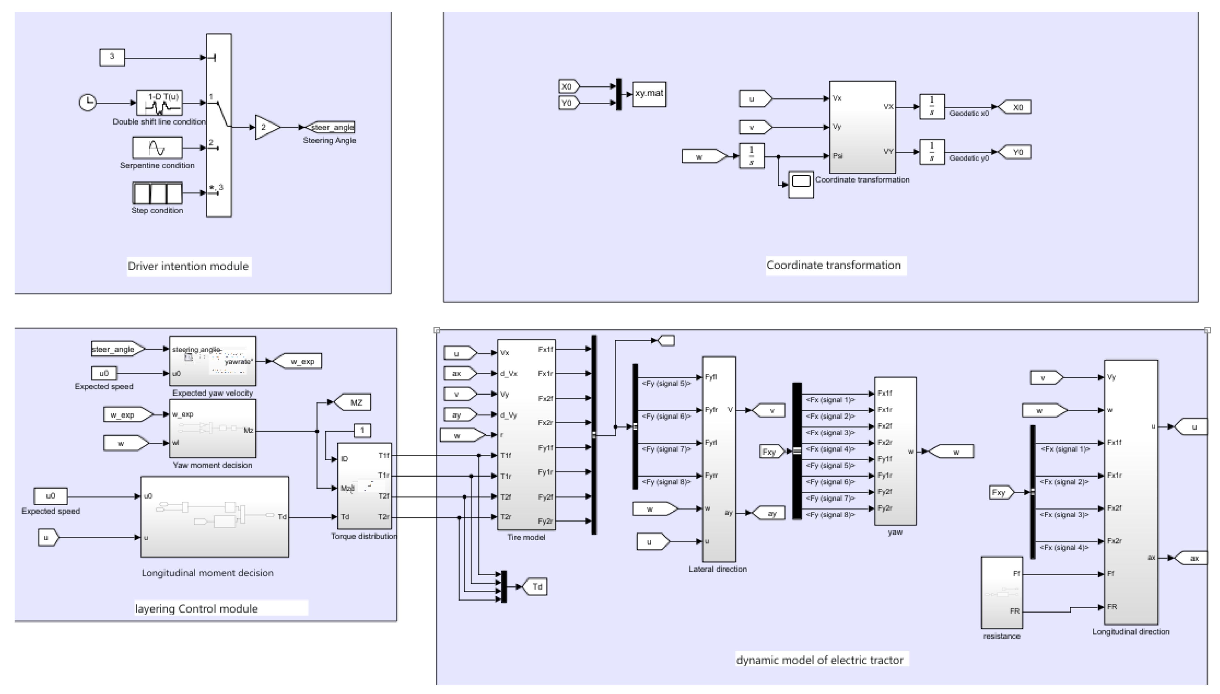
This paper uses MATLAB/Simulink modeling and simulation. The simulation is divided into three modules: driver intention, vehicle dynamics, and layered control, as shown in Figure 5.
The driver’s intention module gives the command signal. The layered control module first decides the longitudinal torque and yaw torque and then distributes the torque to the vehicle dynamics module to complete the simulation experiment.
In this paper, two kinds of performance of electric tractors are tested under three working conditions: steering yaw speed tracking performance and steering stability performance. The driving of the electric tractor mainly relies on the driver’s command signal, and the command signal is mainly the steering command and the driving command signal; the driving command signal is converted into the speed signal, while the steering command signal is given by the driver’s steering wheel angle signal. The steering wheel angle signal corresponds to a yaw speed signal. It is verified that the yaw speed of the electric tractor can track the driver’s intention stably at a certain speed. When turning, the double line shift condition, serpentine condition, and turning condition are selected, and the simulation time is set to 12 s. This paper establishes the PID control and sliding mode control algorithms to compare the yaw velocity tracking control algorithms. The methods of average distribution and optimal distribution are compared, and the test conditions are selected as the double line shift condition, snake condition, and step condition.
a.
Double line shift condition
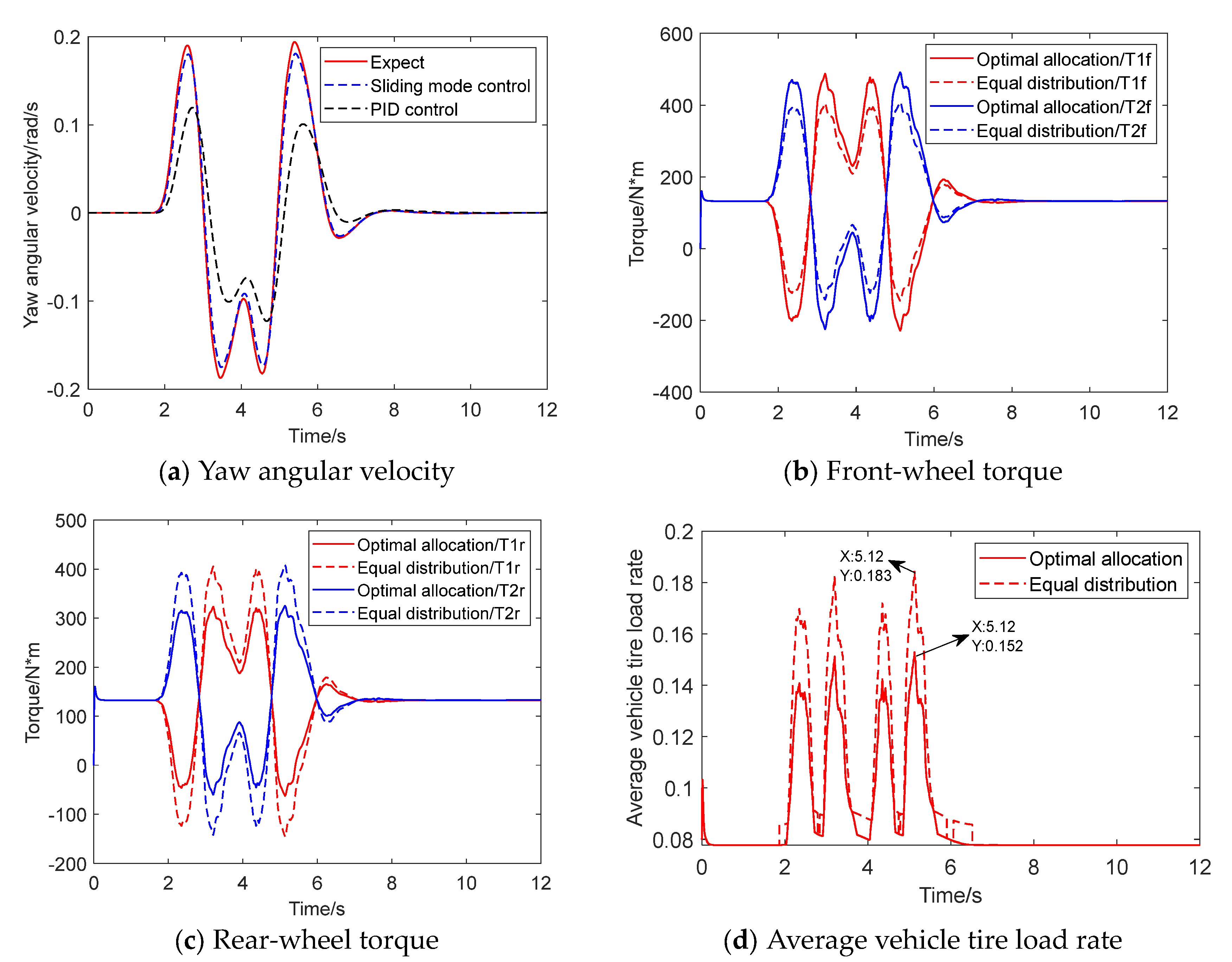
As shown in Figure 6a, the simulation results of the yaw velocity tracking controller show that the tracking effect of yaw velocity tracking using the upper sliding mode controller designed in this paper is superior to PID control. Figure 6b,c show the changes in front and rear wheel torques adopted in the lower layer and the average distribution, and the torque difference between the left and right wheels under the two distribution modes causes the electric tractor to steer. Figure 6d shows the average load rate of the vehicle tire under the two distribution modes. The average load rate of the vehicle tire starts from 0.11, and the average load rate under the average distribution (0.183) and optimal distribution (0.152) reaches the maximum value at 5.12 s. The average load rate of the vehicle tire after optimal distribution is 16.9% lower than the average load rate of the vehicle tire, and the optimal distribution is more stable under the condition of double line shift.
b.
Serpentine condition
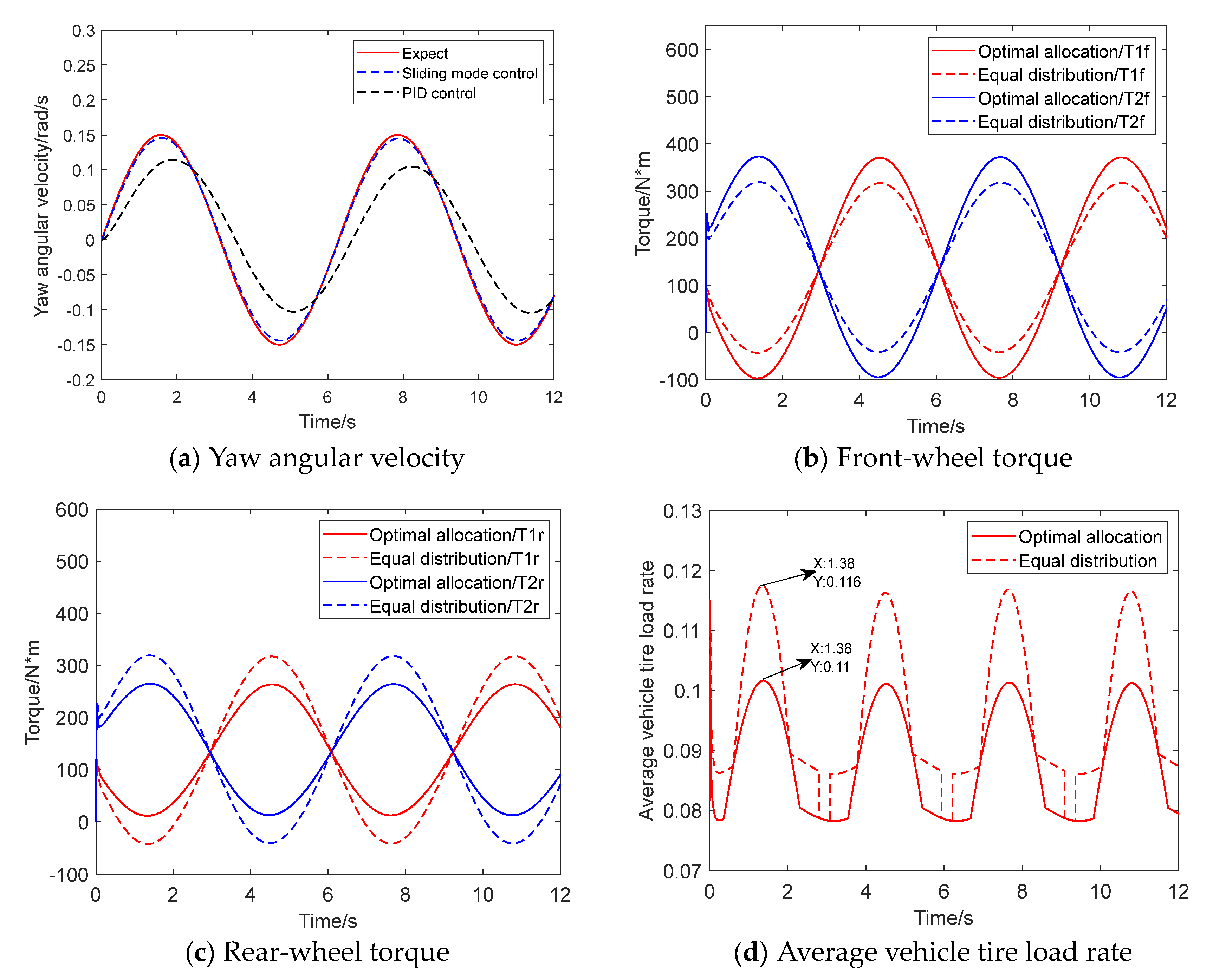
As shown in Figure 7a, the simulation results of the yaw velocity tracking controller show that the tracking performance of yaw velocity tracking using the upper sliding mode controller designed in this paper is superior to PID control. Figure 7b,c show the changes in front and rear wheel torques adopted by the lower layer for optimal distribution and equal distribution. Figure 7d shows the two distribution methods’ average vehicle tire load rate. The average vehicle tire load rate starts from 0.11, and the average vehicle tire load rate of the optimized distribution decreases to 0.078. The average vehicle tire load rate of the average distribution decreases to 0.086. After optimal distribution, the vehicle tire’s mean load rate and the vehicle tire’s average load rate show an inflection point when the steering wheel angle reaches the maximum. The mean load rate of vehicle tire optimized distribution is 0.1, and the mean load rate of vehicle tire averaged distribution is 0.116. The average load rate of the optimized distribution is 13.8% lower than that of the average distribution, and the optimized distribution is more stable under the serpentine condition.
c.
Step condition
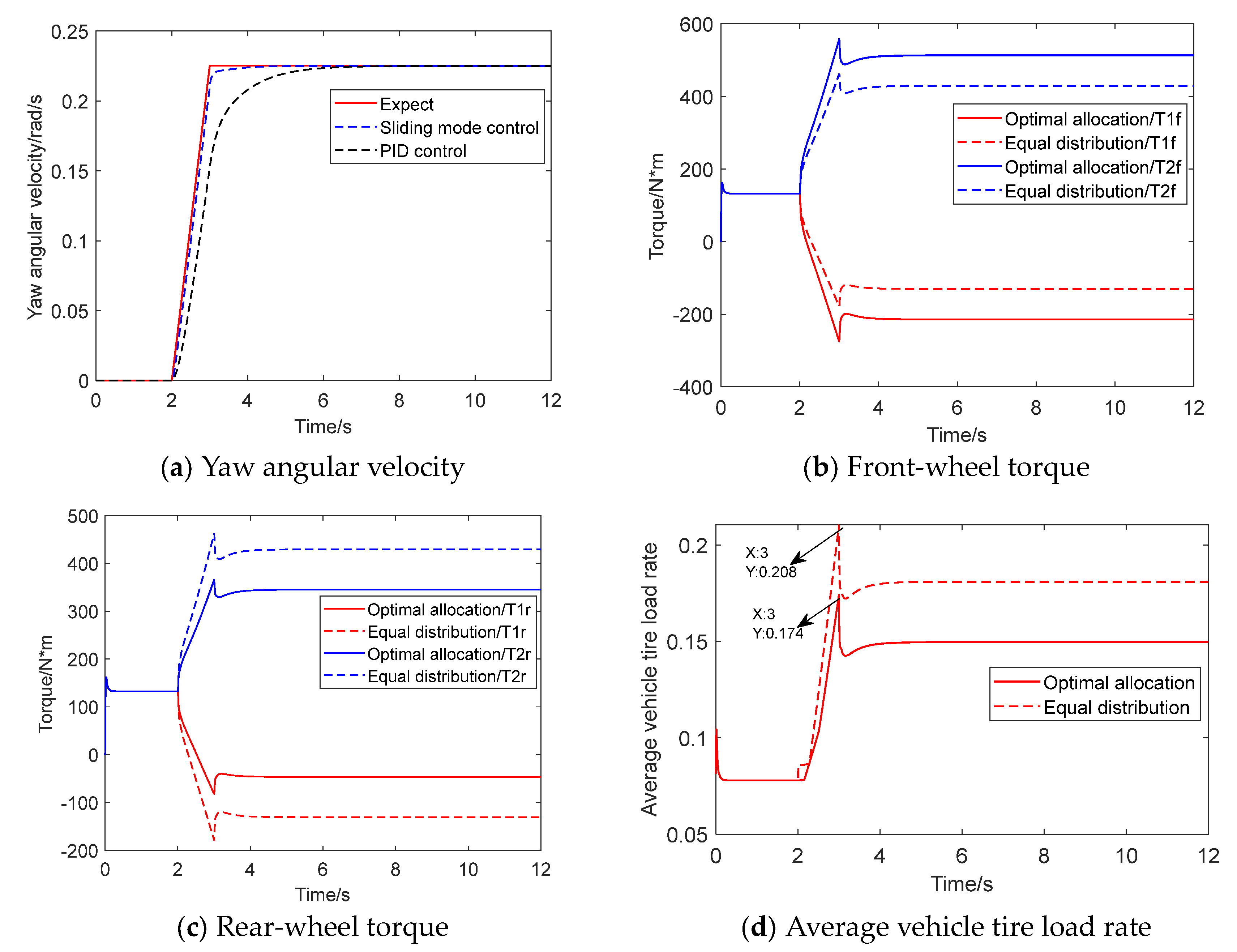
As shown in Figure 8a, the simulation results of the yaw velocity tracking controller show that the tracking performance of yaw velocity tracking using the upper sliding mode controller designed in this paper is superior to PID control. Figure 8b,c show the changes in front and rear wheel torques adopted by the lower layer for optimal distribution and equal distribution. Figure 8d shows the two distribution modes’ average vehicle tire load rate. The average vehicle tire load rate starts from 0.11, and the average vehicle tire load rate of optimal distribution and average distribution is at the inflection point at the steering wheel corner, reaching the maximum value at 0.172 and 0.208, respectively. The optimized vehicle tire load rate distribution decreases by 17.3% compared with the average distribution, which improves the steering stability and is more suitable for complex terrain. Therefore, the optimal allocation algorithm designed in this paper is more helpful in improving the stability of electric tractors.

3.2. Car Test

The control strategy designed in this paper is verified in a simulation experiment. To verify the control strategy intended in this paper, the tracking ability of the control algorithm on the steady-state reference yaw velocity and the torque control effect is investigated in the design circle conditions. The electric tractor is a test prototype, which is not mature yet, and its steering performance is tested. The test scene and results are shown in Figure 9. The test site is the agricultural machinery identification station of the Engineering College of Nanjing Agricultural University. The site is cement pavement, and the site area is 50 m × 60 m.
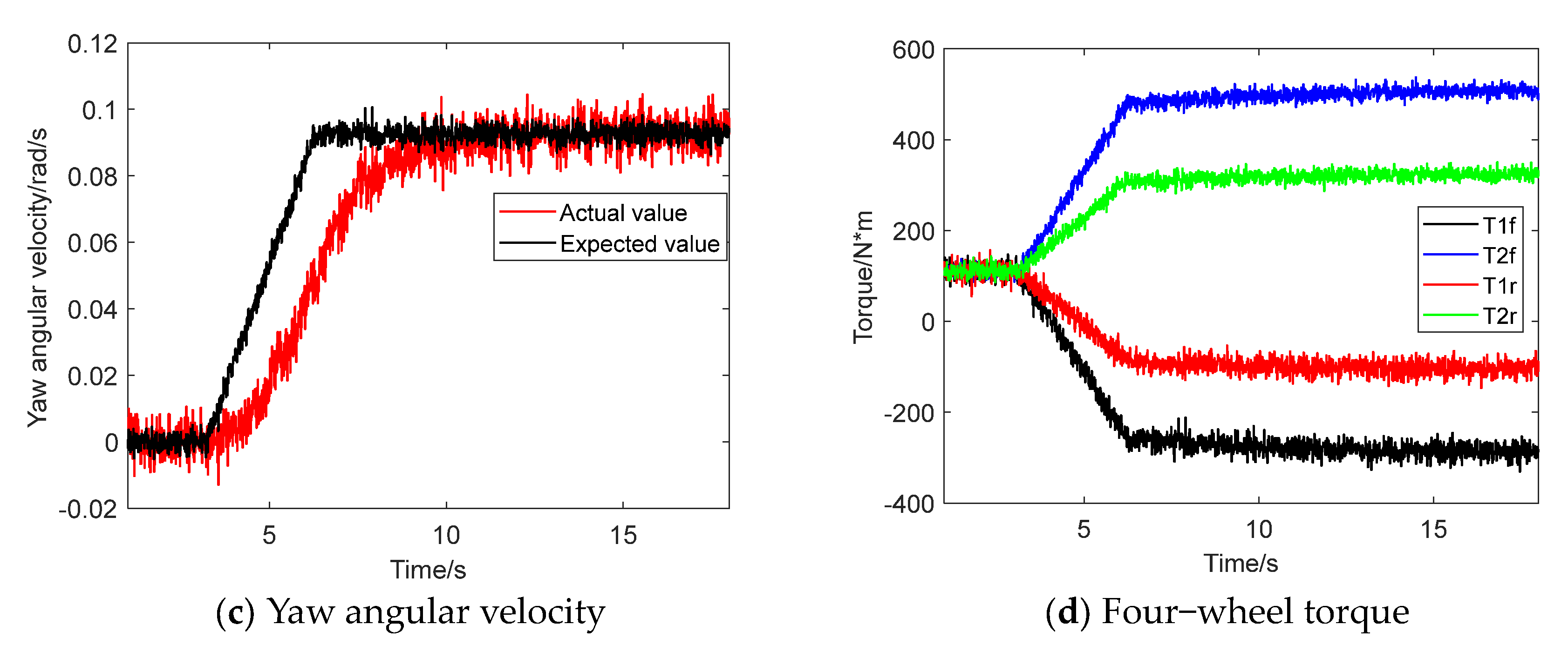
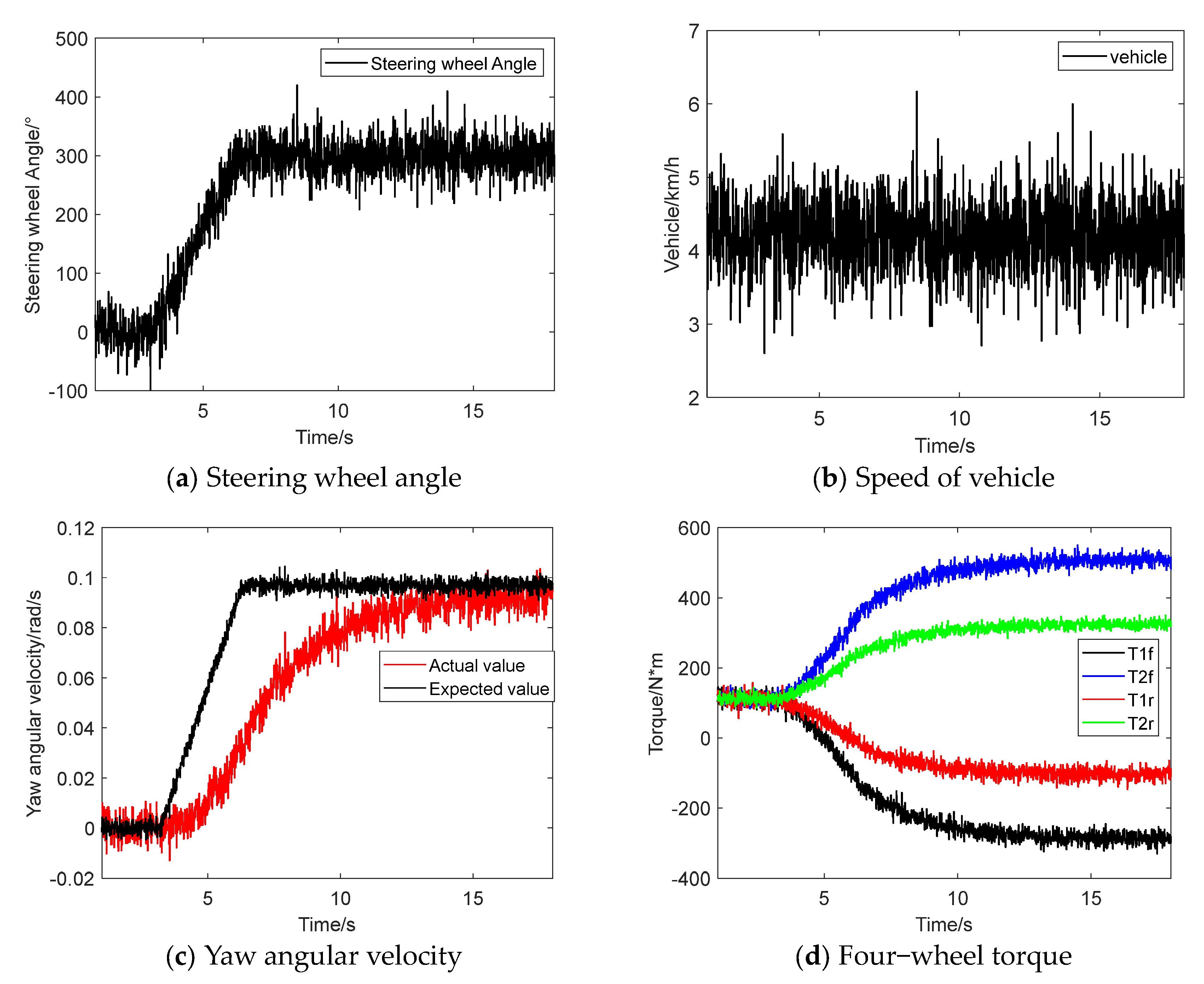
Test method: The yaw force algorithm of sliding mode control and the yaw moment algorithm of PID control are compiled and downloaded into the vehicle controller, and the torque distribution is optimized. Considering the safety of the test, the accelerator pedal is pressed slowly first, and the test speed is maintained at about 4 km/h. When the steering wheel starts to turn at 3 s, the steering wheel angle quickly reaches the maximum at 6 s. At the same time, the steering wheel angle, speed, expected yaw speed, actual yaw speed, and wheel torque signal are recorded in Figure 10 and Figure 11, showing the data acquisition results of real vehicle tests. A second-order Butterworth low-pass filter with a cut-off frequency of 20 Hz is used to filter high-frequency pulse signals to obtain the test data of the electric tractor.
Figure 10a and Figure 11a show the steering wheel angle signal during the real vehicle test. It can be seen from Figure 10b and Figure 11b that the vehicle speed is controlled by the driver operating the accelerator pedal and brake pedal; hence, the vehicle speed cannot be wholly constant but fluctuates around 4 km/h. Figure 10c and Figure 11c show that both the sliding mode control and PID control designed in this paper can follow the driver’s intention. When turning in road conditions, it can be found that the expected yaw speed changes linearly with the steering wheel angle. The yaw speed under the sliding mode control strategy follows the expected yaw speed at about 10 s, reaching 0.093 rad/s. The yaw speed under the PID control strategy follows the expected yaw speed at about 13 s. The sliding mode control strategy is better than the PID control cabinet strategy. Figure 10d and Figure 11d show the results of four-wheel torque distribution at this time, realizing the torque distribution control.

4. Conclusions

The four-wheel independent drive differential steering mode differs from the traditional Ackermann steering mode, which realizes steering by controlling the inner and outer wheel torque, which can accurately show the working state of high-end agricultural machinery equipment and improve the operating efficiency of agricultural machinery equipment. Aiming at the dynamic control problem of four-wheel independent drive electric tractor steering, this paper introduced the tire force model and established the whole dynamic model of the tractor. The relationship between steering wheel angle and tractor longitudinal velocity difference ratio was established in the differential steering model based on the Ackermann steering model.
The research object of this paper was the four-wheel independent drive electric tractor. Each motor was independent and controllable, thus involving the torque distribution of each motor. Compared with the traditional controller, the controller designed in this paper adopted the layered control structure, which could directly generate the motor drive torque instructions of four wheels for dynamic control. The upper level was based on a sliding mode controller designed to quickly and stably track the desired yaw rate. In the lower layer, a torque distribution controller based on the mean load rate of the whole vehicle tire was proposed, which could significantly improve the stability of tractor movement and prevent accidents such as side roll and side slip.
The effect of the controller was simulated under double line shift, serpentine, and step conditions, and the results showed that the sliding mode control was better than PID control in driver intention tracking. The optimal allocation strategy was better than the average allocation strategy, and the average maximum load rate of the vehicle tire under the three working conditions was reduced by 16.9%, 13.8%, and 17.3%, respectively. To ensure that the designed controller could be used stably and effectively in practice, a real tractor was built to test the algorithm. The results showed that the sliding mode control algorithm was better than the PID algorithm in tracking the driver’s intention. This study has important guiding significance for improving the maneuverability and stability of electric tractors.

Author Contributions

Methodology, Y.A.; software, Y.A. and L.W.; validation, Y.A.; investigation, Y.A. and L.W.; resources, Z.L. and X.D.; writing—original draft preparation, X.D. and H.C.; writing—review and editing, Y.A., T.W. and Z.L.; supervision, Z.L.; project administration, Z.L. and T.W. All authors have read and agreed to the published version of the manuscript.

Funding

This study was funded by the Open Project of the State Key Laboratory of Intelligent Agricultural Power Equipment (SKLIAPE2023019) and the National Key Research and Development Plan (2022YFD2001202).

Institutional Review Board Statement

Not applicable.

Data Availability Statement

The data presented in this study are available on demand from the corresponding author or first author at [email protected] or [email protected].

Acknowledgments

The authors thank the National Key Research and Development Plan (2022YFD2001202) and the Open Project of the State Key Laboratory of Intelligent Agricultural Power Equipment (SKLIAPE2023019) for funding. The authors also thank the anonymous reviewers for providing critical comments and suggestions that improved the manuscript.

Conflicts of Interest

The authors declare no conflict of interest.

References

  1. Liu, M.N.; Lei, S.H.; Zhao, J.H.; Meng, Z.J.; Zhao, C.J.; Xu, L.Y. Review on development and Research Status of Electric Tractor. Trans. Chin. Soc. Agric. Mach. 2022, 53, 348–364. [Google Scholar]
  2. Xie, B.; Wu, Z.B.; Mao, E.R. Development and the prospect of key technologies on agricultural tractor. Trans. Chin. Soc. Agric. Mach. 2018, 49, 1–17. [Google Scholar]
  3. Oscar, L.; Gunnar, L.; Anders, L.; Per-Anders, H. Impact of lowered vehicle weight of electric autonomous tractors in a systems perspective. Smart Agric. Technol. 2023, 4, 100156. [Google Scholar]
  4. Li, Z.C.; Li, J.Q.; Yang, S. The study on Differential Steering Control of In-wheel Motor Vehicle Based on Double Closed Loop System. En. Proc. 2018, 152, 586–592. [Google Scholar] [CrossRef]
  5. Fernandez, B.; Herrera, P.J.; Cerrada, J. Robust digital control for autonomous skid-steered agricultural robots. Comput. Electron. Agric. 2018, 153, 94–101. [Google Scholar] [CrossRef]
  6. Cao, F.Y.; Zhou, Z.L.; Zhao, J.H. Design of Steering Wheel Control System of Tracked Vehicle of Hydro-Mechanical Differential Turning. Adv. Mater. Res. 2012, 1671, 472–475. [Google Scholar] [CrossRef]
  7. Maclaurin, B. A skid steering model with track pad flexibility. J. Terramech. 2007, 44, 95–110. [Google Scholar] [CrossRef]
  8. Maclaurin, B. A skid steering model using the Magic Formula. J. Terramech. 2011, 48, 247–263. [Google Scholar] [CrossRef]
  9. Maclaurin, B. Comparing the steering performance of skid and Ackermann-steered vehicles. Proc. Inst. Mech. Eng. D J. Automob. Eng. 2008, 222, 739–756. [Google Scholar] [CrossRef]
  10. Yu, W.; Chuy, O.Y.; Collins, E.G.; Hollis, P. Analysis and experimental verification for dynamic modeling of a skid-steered wheeled vehicle. IEEE Trans. Robot. 2010, 26, 340–353. [Google Scholar] [CrossRef]
  11. Mokhiamar, O.; Amine, S. Lateral motion control of skid steering vehicles using full drive-by-wire system. J. Alex Eng. 2017, 56, 383–394. [Google Scholar] [CrossRef]
  12. Du, P.; Ma, Z.M.; Chen, H.; Xu, D.; Wang, Y.; Jiang, Y.H.; Lian, X.M. Speed-adaptive motion control algorithm for differential steering vehicle. Proc. Inst. Mech. Eng. D J. Automob. Eng. 2021, 235, 672–685. [Google Scholar] [CrossRef]
  13. Ni, J.; Hu, J.; Xiang, C. Robust path following control at driving handling limits of an autonomous electric racecar. IEEE Trans. Veh. Technol. 2019, 68, 5518–5526. [Google Scholar] [CrossRef]
  14. Shino, M.; Nagai, M. Independent wheel torque control of small-scale electric vehicle for handling and stability improvement. JSAE Rev. 2003, 24, 449–456. [Google Scholar] [CrossRef]
  15. Xu, D.; Wang, G.D.; Cao, B.G.; Feng, X.H. Research on torque optimal allocation strategy of independent drive electric vehicle. J. Xian Jiao Tong Univ. 2012, 46, 42–46. [Google Scholar]
  16. Li, Q.W.; Zhang, H.H.; Yan, S.; Gao, C. Single wheel failure stability control for four-wheel independent drive electric vehicles. Control Eng. 2021, 28, 155–163. [Google Scholar]
  17. Yan, Y.B.; Zhang, Y.N.; Yan, N.M.; Han, B.L. Simulation Research on motion control algorithm of six wheel independent drive sliding steering vehicle. J. Ordnance Ind. 2013, 34, 1461–1468. [Google Scholar]
  18. Kang, J.; Kim, W.; Lee, J.; Yi, K. Skid steering-based control of a robotic vehicle with six in-wheel drives. Proc. Inst. Mech. Eng. D J. Automob. Eng. 2010, 224, 1369–1391. [Google Scholar] [CrossRef]
  19. Lu, Y.J.; Yang, S.P.; Li, S.H. Research on dynamics of a class of heavy vehicle-tire-road coupling system. Sci. Sci. China Technol. Sci. 2011, 54, 2054–2063. [Google Scholar] [CrossRef]
  20. Li, Y.X.; Wang, Y.C.; Feng, P.F. Lateral Dynamics of Three-axle Steering Vehicle Based Zero Vehicle Sideslip Angle Control. New Mater. New Process. 2012, 476, 1682–1687. [Google Scholar] [CrossRef]
  21. Rezaeian, A.; Zarringhalam, R.; Fallah, S.; Melek, W.; Khajepour, A.; Chen, S.K.; Moshchuck, N.; Litkouhi, B. Novel Tire Force Estimation Strategy for Real-Time Implementation on Vehicle Applications. Trans. Vehicle Tec. 2015, 64, 2231–2241. [Google Scholar] [CrossRef]
  22. Xiong, L.; Huang, S.S.; Chen, Y.L.; Yang, G.X.; Zhang, R. Research on motion tracking control of wheeled differential steering unmanned vehicle. Auto. Eng. 2015, 37, 1109–1116. [Google Scholar]
  23. Yu, Z.P.; Gao, L.T.; Zhang, R.X.; Xiong, L. Wheel motor drives differential steering vehicle dynamics control. J. Tongji Univ. Nat. Sci. 2018, 46, 631–638. [Google Scholar]
  24. Cho, J.; Huh, K. Active Front Steering for Driver’s Steering Comfort and Vehicle Driving Stability. Int. J. Auto. Technol. 2019, 20, 589–596. [Google Scholar] [CrossRef]
  25. Jeong, D.; Kim, S.T.; Choi, S.B.; Kim, M.; Lee, H.J. Estimation of Tire Load and Vehicle Parameters Using Intelligent Tires Combined With Vehicle Dynamics. IEEE Trans. Instrum. Meas. 2018, 70, 101109. [Google Scholar] [CrossRef]
  26. Grecenko, A.; Prikner, P. Tire rating based on soil compaction capacity. J. Terramech. 2014, 52, 77–92. [Google Scholar] [CrossRef]
  27. Liu, J.; Sun, F. Research and Progress of Sliding Mode Variable Structure Control Theory and its Algorithms. Control. Theory Appl. 2007, 24, 407–418. [Google Scholar]
  28. Wu, D.M.; Li, Y.; Zhang, J.W.; Du, C.Q. Torque distribution of a four in-wheel motors electric vehicle based on a PMSM system model. Proc. Inst. Mech. Eng. D J. Automob. Eng. 2018, 232, 1828–1845. [Google Scholar] [CrossRef]
Figure 1. Wheel speed analysis.
Agriculture 13 01758 g001
Figure 2. Dynamic analysis of differential steering for electric tractor.
Agriculture 13 01758 g002
Figure 3. Layered control strategy for differential steering of electric tractor.
Agriculture 13 01758 g003
Figure 4. Overall layout of electric tractor.
Agriculture 13 01758 g004
Figure 5. Electric tractor simulation model.
Agriculture 13 01758 g005
Figure 6. Simulation results of double line shift conditions.
Agriculture 13 01758 g006
Figure 7. Simulation results of serpentine condition.
Agriculture 13 01758 g007
Figure 8. Simulation results of step condition.
Agriculture 13 01758 g008
Figure 9. Electric tractor performance test diagram.
Agriculture 13 01758 g009
Figure 10. Test data of yaw moment controlled by sliding mode.
Agriculture 13 01758 g010aAgriculture 13 01758 g010b
Figure 11. Test data of yaw moment controlled by PID.
Agriculture 13 01758 g011
Table 1. Electric tractor vehicle parameters.
NameArgumentNumerical ValueUnit
Total tractor mass m 2105kg
Tractor wheelbase L 2.05m
Distance from center of mass to front axis a 0.82m
Distance from center of mass to rear axis b 1.23m
Tractor wheel gauge B 2.12m
Principal moment of inertia around the z-axis I z 2537kg·m2
Wheel radius R e 0.53m
Wheel inertia J i 11.52kg·m2
Disclaimer/Publisher’s Note: The statements, opinions and data contained in all publications are solely those of the individual author(s) and contributor(s) and not of MDPI and/or the editor(s). MDPI and/or the editor(s) disclaim responsibility for any injury to people or property resulting from any ideas, methods, instructions or products referred to in the content.