
Soil Moisture Detection and Linear Deceleration Control Strategy Enhancing Trenching Depth Precision and Stability for Rapeseed Sowing


Abstract
:1. Introduction
2. Materials and Methods
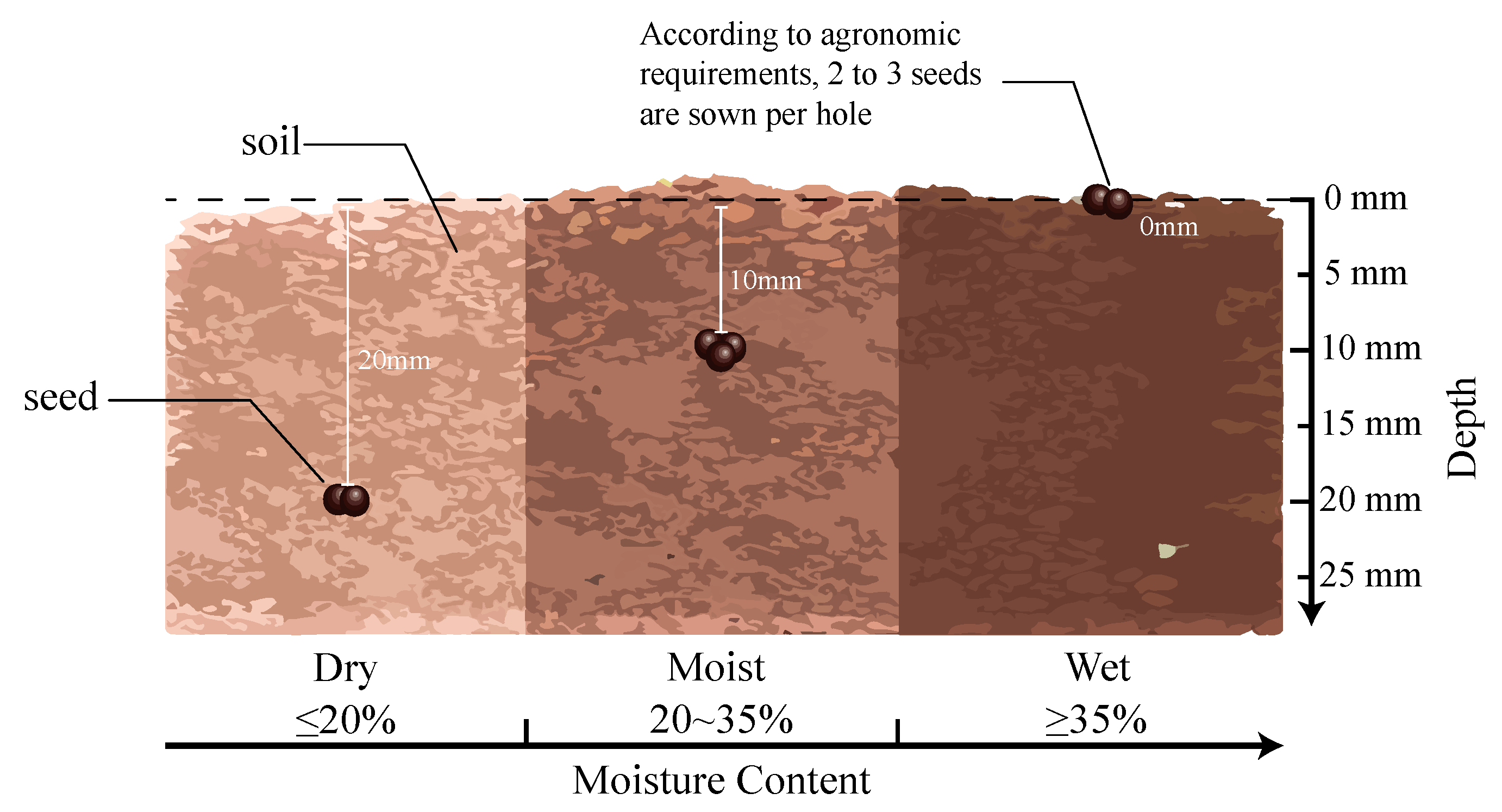
2.1. Planting Pattern of Rape Seeding
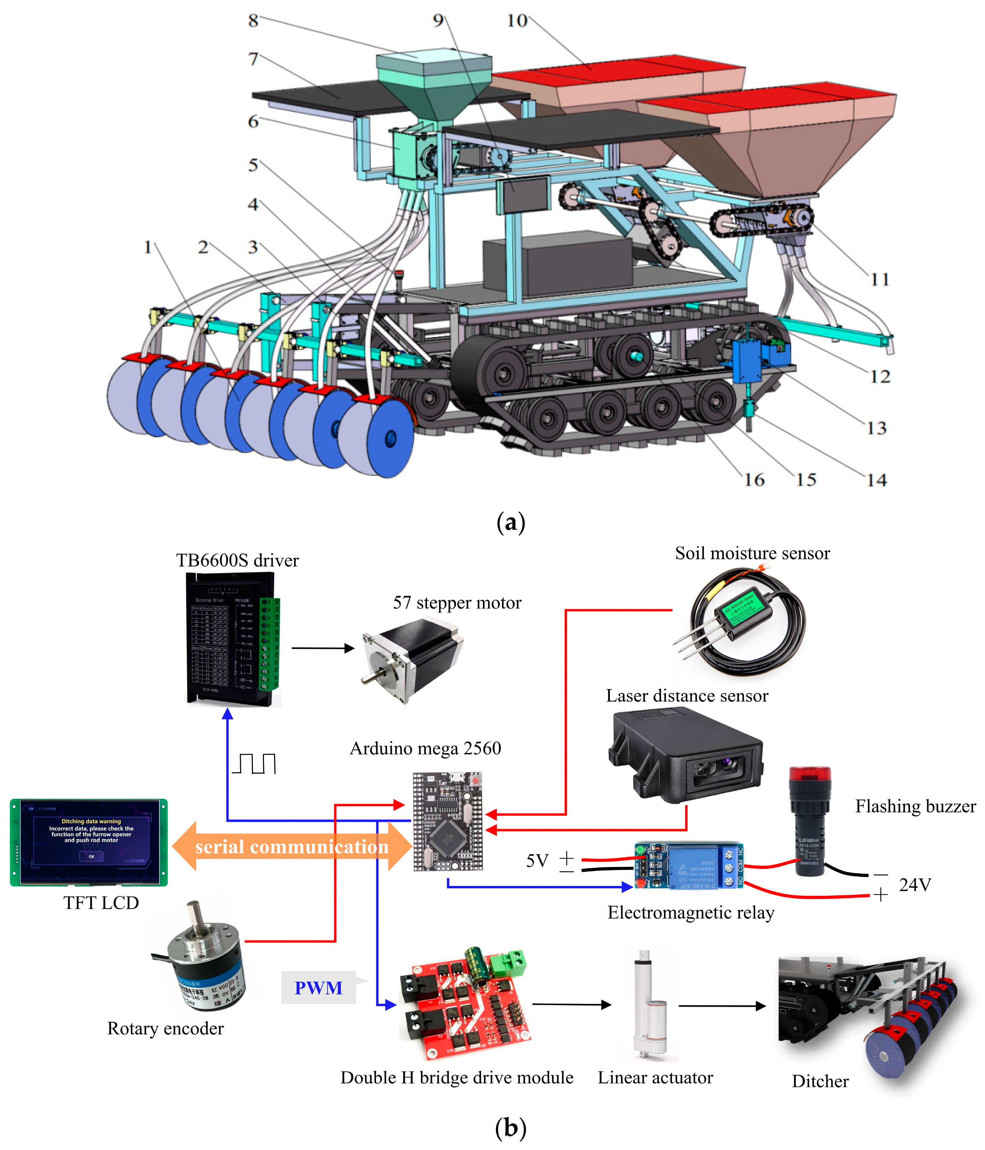
2.2. The Structure and Working Principle of the Seeder
2.3. Hardware Design
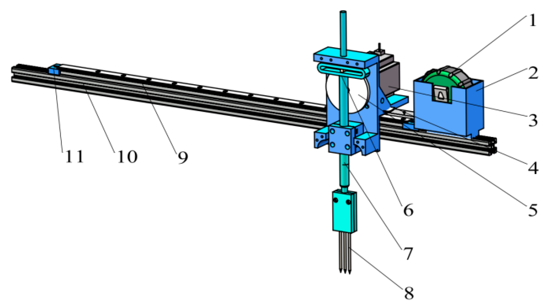
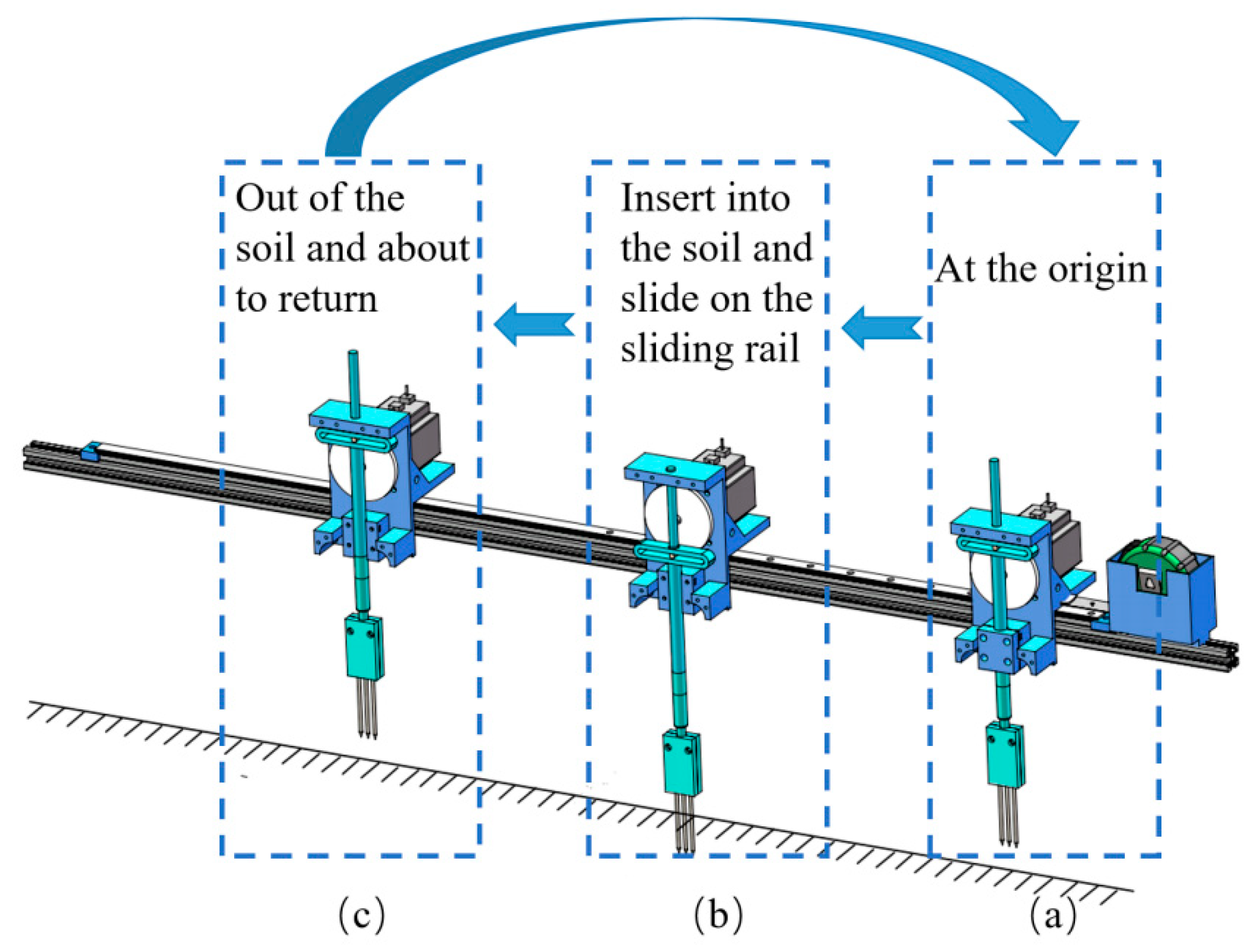
2.3.1. Soil Moisture Detection Device
2.3.2. Automatic Sowing Depth Adjustment Device
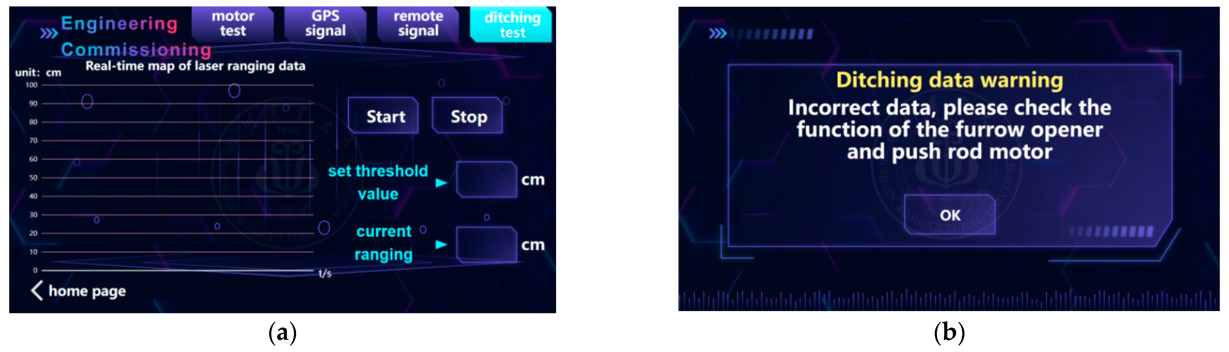
2.4. Control Strategy
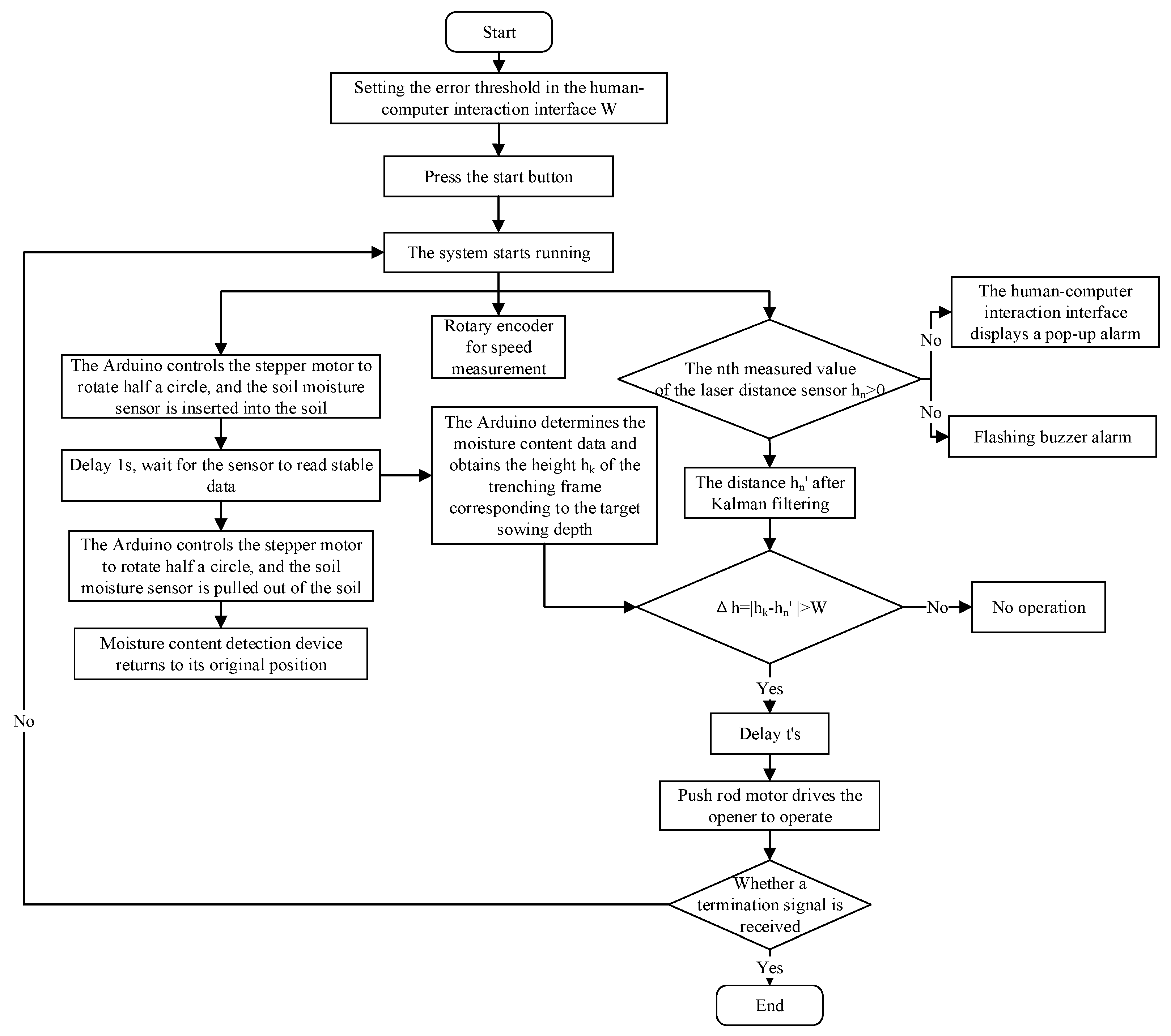
2.4.1. Control Method of Soil Moisture Detection System
2.4.2. Control Strategy of Automatic Adjustment System for Sowing Depth
- (1)
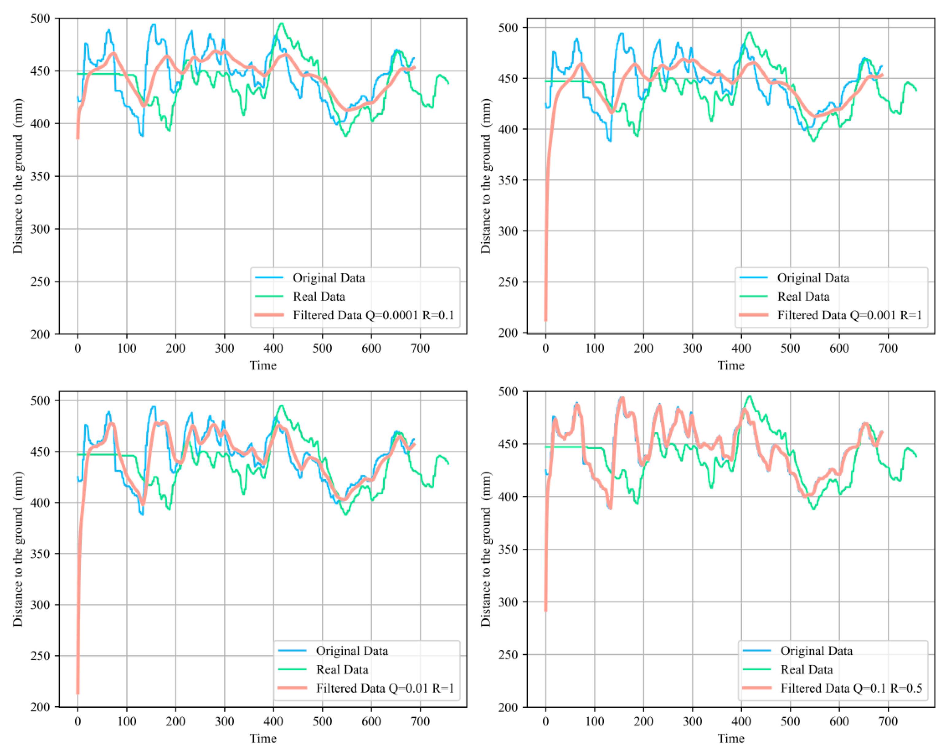
- Kalman filter algorithm.
- (2)
- Mathematical model of control system.
- (3)
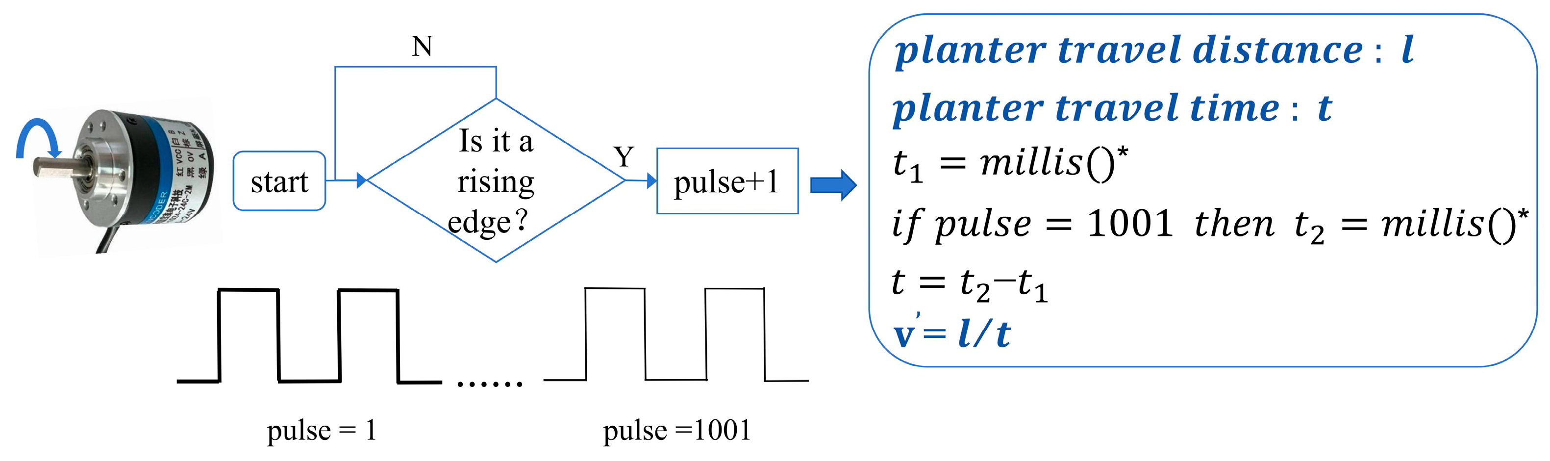
- Delay calculation strategy.
- (4)
- Control of actuator motor.
2.4.3. Control Method for Adjusting Sowing Depth Based on Soil Moisture Content
3. Results and Analysis
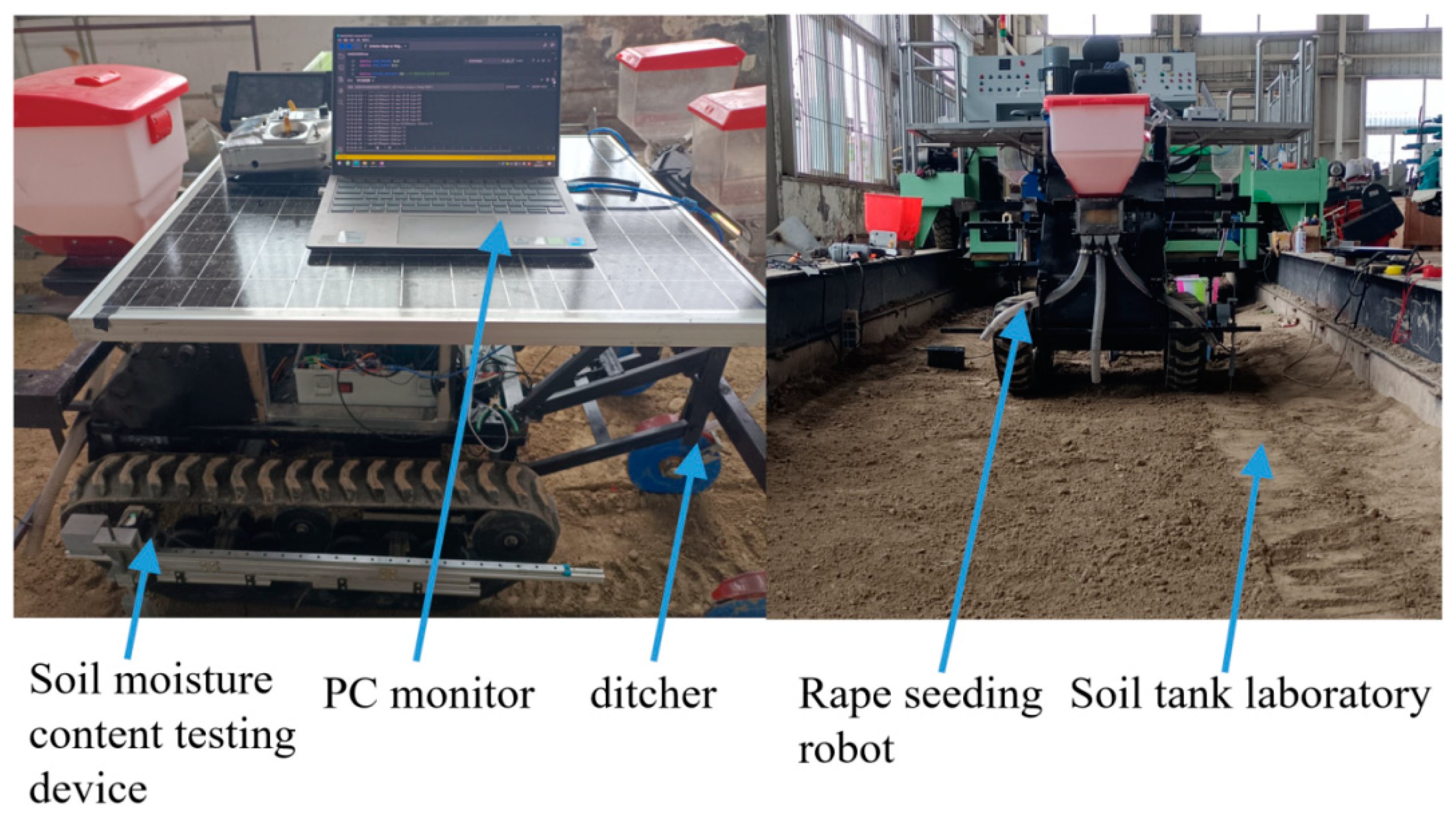
3.1. Experimental Test Conditions and Equipment
3.2. Control Performance Test
3.3. Sowing Depth Accuracy Test
3.4. Depth Automatic Adjustment and Non-Adjustment Comparison Test
4. Conclusions
- (1)
- The soil moisture detection device was designed to automating test the soil moisture content sensor. A control equation of “linear deceleration” and a Kalman filter algorithm were proposed to ensure precise operation of the furrowing depth. The optimal parameters were an observation noise covariance matrix (Q/R) of 0.001, a deceleration range of 40 mm, and a minimum speed of 10. This control strategy therefore shortened response times and enhanced stability and precision.
- (2)
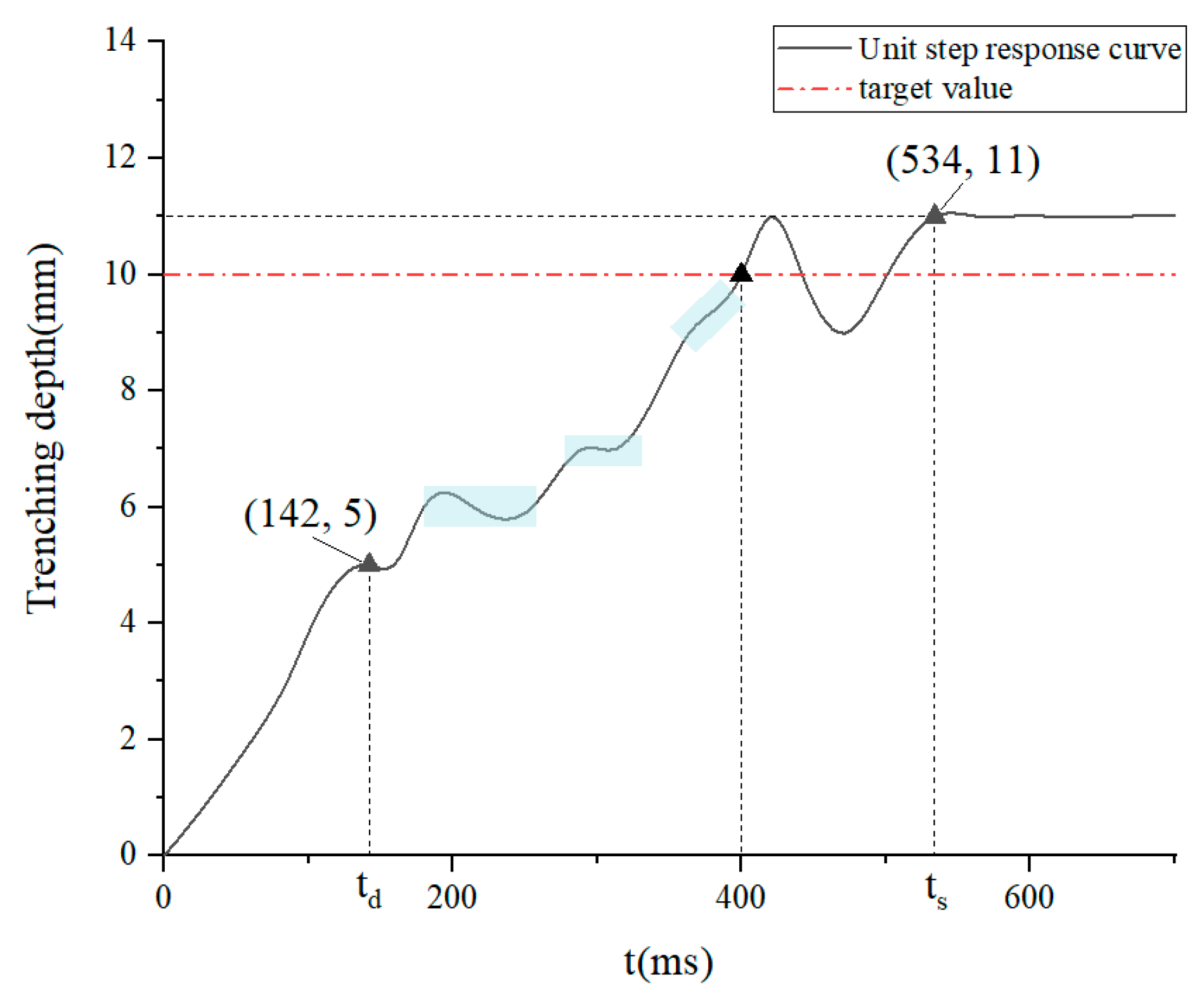
- The simulation and test of the control system’s precision and reliability were conducted. The control system adjustment time (ts) was found to be 534 ms and the steady-state error was within 1 mm.
- (3)
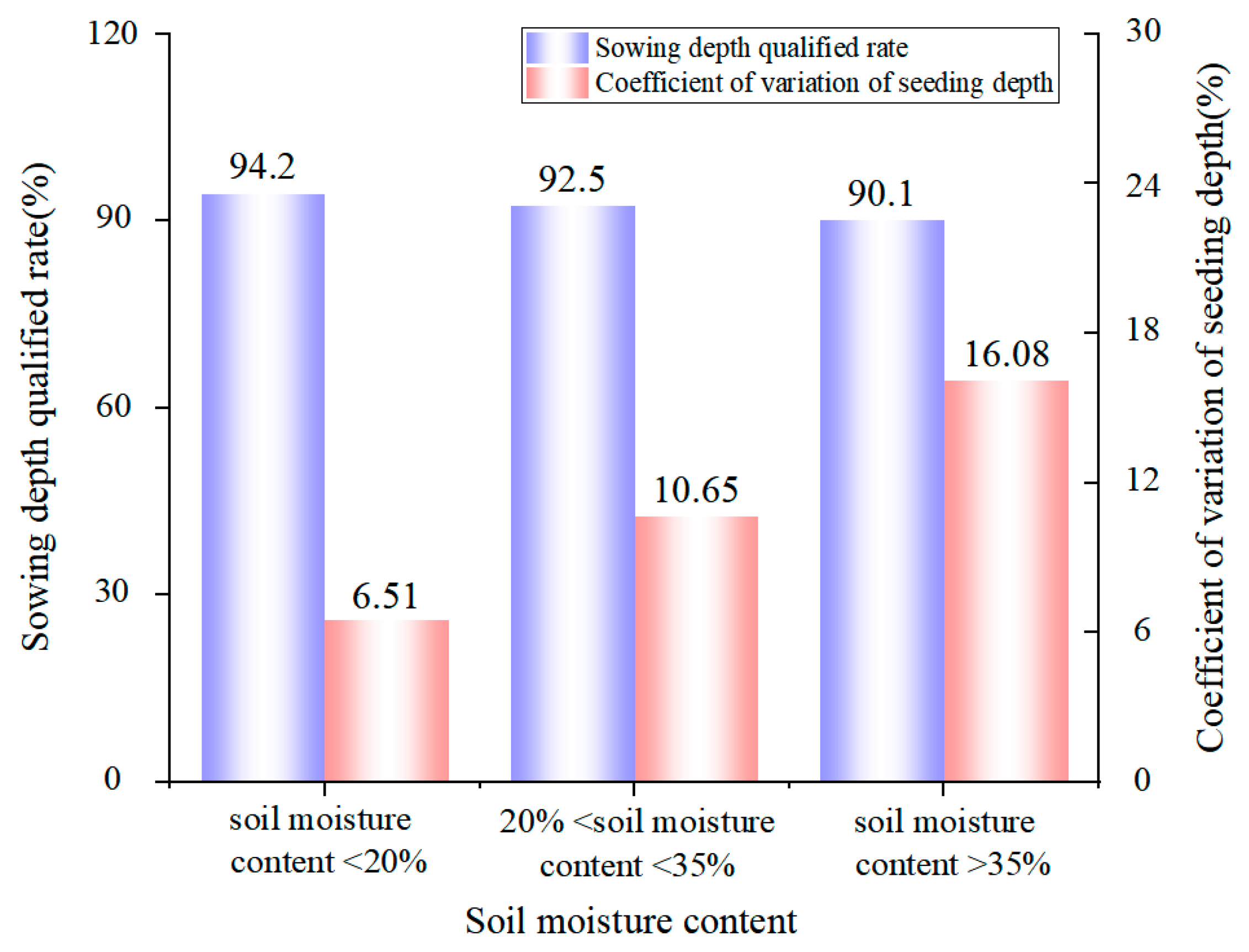
- The trenching depth test demonstrated that under three different soil moisture content conditions, the sowing depth qualification rate and stability coefficients consistently surpassed 90 and 80%, respectively. The qualification rate of sowing depth with automatic adjustment increased by 61.7 percentage points compared to the non-adjusted treatment. The coefficient of variation decreased by 45.81 percentage points. This suggested that the automatic adjustment sowing depth system exhibited excellent performance, characterized by high control accuracy and good stability. Consequently, this control system can more effectively regulate sowing depth.
Author Contributions
Funding
Institutional Review Board Statement
Data Availability Statement
Conflicts of Interest
References
- Yang, Z.P.; Li, S.S.; Ma, M.K.; Zheng, S.H.; Wang, K.J.; Ao, Y.Q.; Wan, X.; Song, X.; Liu, D.H.; Chen, S.H.; et al. Characteristics and development trend of rapeseed production layout in Sichuan province. China Oils Fats 2024, 49, 1–10. [Google Scholar]
- Nielsen, S.K.; Munkholm, L.J.; Lamandé, M.; Nørremark, M.T.C.; Edwards, G.; Green, O.; Yugang, F. Seed drill depth control system for precision seeding. J. Chin. Agric. Mech. 2021, 42, 30–36. [Google Scholar]
- Liu, L.; Wang, X.; Zhang, X.; Cheng, X.; Wei, Z.; Ji, J.; Li, H.; Zhang, H.; Wang, M. Sowing depth control strategy based on the downforce measurement and control system of ‘t’-shaped furrow opener. Biosyst. Eng. 2024, 247, 97–108. [Google Scholar] [CrossRef]
- Brune, P.F.; Ryan, B.J.; Technow, F.; Myers, D.B. Relating planter downforce and soil strength. Soil Tillage Res. 2018, 184, 243–252. [Google Scholar] [CrossRef]
- Fan, L.P.; Ma, J.J. Design on broadcast depth detection device based on Kalman filter fusion algorithm. Ind. Instrum. Autom. 2024, 54, 7–12. [Google Scholar]
- Shi, L.; Zhao, B.; Yi, S.J.; Kuang, L.H.; Zhao, N.C.; Liu, H.W. An intelligent control system for seeding depth based on the pressure and angle of the depth-limiting arm of the seeding unit. J. Chin. Agric. Mech. 2024, 46, 9–13. [Google Scholar]
- Xue, B.; Ming, Z.L.; Niu, K.; Zheng, Y.K.; Bai, S.H.; Wei, L.A. Research of sowing depth based on adaptive fuzzy PID control system of wheat planter. Trans. Chin. Soc. Agric. Mach. 2023, 54, 1–12. [Google Scholar]
- Huang, D.Y.; Zhu, L.T.; Jia, H.L.; Yu, T. Automatic control system of seeding depth based on piezoelectric film for no-till planter. Trans. Chin. Soc. Agric. Mach. 2015, 46, 1–8. [Google Scholar]
- Zhao, M.M.; Hao, X.Z.; Zhao, T.C.; He, L.N.; He, R.Y. Design and test of a trenching depth control system based on laser sensor. J. South Chin. Agric. Univ. 2018, 39, 91–96. [Google Scholar]
- Li, Y.H.; Meng, P.X.; Geng, D.Y.; He, K.; Meng, F.H.; Jiang, M. Intelligent system for adjusting and controlling corn seeding depth. J. Chin. Agric. Mech. 2016, 47, 62–68+42. [Google Scholar]
- Liang, F.; Lei, Q.A.; Zheng, S.Y.; Wang, P.; Guo, Z.; Liu, W. Design and experiment of electro-hydraulic profiling system with consistent pressure for drilling depth of furrow opener. Trans. Chin. Soc. Agric. Eng. 2019, 35, 1–8. [Google Scholar]
- Zhao, J.H.; Liu, L.J.; Yang, X.J.; Liu, Z.J.; Tang, J.X. Design and laboratory test of control system for depth of furrow opening. Trans. Chin. Soc. Agric. Eng. 2015, 31, 35–41. [Google Scholar]
- Cortes Burce, M.E.; Kataoka, T.; Okamoto, H. Seeding depth regulation controlled by independent furrow openers for zero tillage systems: Part 1: Appropriate furrow opener. Eng. Agric. Environ. Food 2013, 6, 1–6. [Google Scholar]
- Cortes Burce, M.E.; Kataoka, T.; Okamoto, H.; Shibata, Y. Seeding depth regulation controlled by independent furrow openers for zero tillage systems: Part 2: Control system of independent furrow openers. Eng. Agric. Environ. Food 2013, 6, 13–19. [Google Scholar]
- Liu, L.C. Ditching Device Design and Soil Surface Quality Study of No-Tillage Direct Seeder for Rapeseed. Ph.D. Thesis, Huazhong Agricultural University, Wuhan, China, 2019. [Google Scholar]
- Zhang, Q.S.; Qi, T.; Ao, Q.; Shu, C.X.; Liao, Y.T.; Liao, Q.X. Design and experiment of rapeseed direct seeding machine with furrow opener and shallow plowing. Trans. Chin. Soc. Agric. Mach. 2023, 54, 58–67, 104. [Google Scholar]
- Xue, B.; Ming, Z.L.; Niu, K.; Zheng, Y.K.; Bai, S.H.; Wei, L.A. Sowing depth control system of wheat planter based on adaptive fuzzy PID. Trans. Chin. Soc. Agric. Mach. 2023, 54, 93–102. [Google Scholar]
- Cao, X.P.; Wang, Q.G.; Xu, D.J.; Huang, S.H.; Wang, X.H.; Wang, L.B. Design and analysis of pneumatic downforce regulating device for no-till corn planter. Agriculture 2022, 12, 1513. [Google Scholar] [CrossRef]
- Nielsen, S.K.; Nørremark, M.; Green, O. Sensor and control for consistent seed drill coulter depth. Comput. Electron. Agric. 2016, 127, 690–698. [Google Scholar] [CrossRef]
- Shang, J.J.; Liu, D.M.; Song, X.T.; Han, Y.B.; He, S.T.; Zhang, Y.; Liu, L.Y.; Chen, H.T. Sowing depth stability analysis and test verification of no-tillage planter parallel four-bar row unit. Heliyon 2024, e36721. [Google Scholar] [CrossRef]
- Sang, X.C.; Zhang, K.L.; Yang, L.; Zhang, D.X.; Cui, T.; He, X.T.; Qi, H.J.; Mou, J.S. Design and experiment of a stereoscopic vision-based system for seeding depth consistency adjustment. Comput. Electron. Agric. 2024, 225, 109345. [Google Scholar] [CrossRef]
- Zhang, Q.S.; Liao, Q.X.; Xiao, W.L.; Liu, X.P.; Wei, G.L.; Liu, L.C. Research process of tillage technology and equipment for rapeseed growing. Chin. J. Oil Crop Sci. 2018, 40, 702–711. [Google Scholar]
- Li, Z. Different Soil Temperature and Humidity in Different Cultivation and Their Effects on the Yield of Rapeseed (Brassica napus L.). Master’s Thesis, Hunan Agricultural University, Changsha, China, 2018. [Google Scholar]
- Guo, X.; Zhao, J.P.; Wang, R.L.; Li, X.Y. Spatiotemporal characteristics and risk of waterlogging damage during rape sowing period in Sichuan basin, China. Chin. J. Ecol. 2022, 41, 1406–1413. [Google Scholar]
- Li, L.L.; Jie, Y.C.; Zhao, L.; Liu, X.C.; Zhang, L. Current status and control strategy for waterlogging damage in oilseed rape in the yangtze river basin:A review. Jiangsu Agric. Sci. 2024, 52, 1–10. [Google Scholar]
- He, D.; Hu, P.C.; Wang, J.; Wang, L.; Fang, S.B. Distribution characteristics of winter canola yield potential and yield gap in the Yangtze river basin. Shandong Agric. Sci. 2023, 55, 174–180. [Google Scholar]
- Li, G.C.; Niu, Q.C.; Leng, B.F.; Ding, Y.F.; Tong, T.; Fan, L.X. The decade of rapeseed industry in the new era: Development and its path choice. Chin. J. Oil Crop Sci. 2024, 46, 228–235. [Google Scholar]
- Srivastava, A.K.; Goering, C.E.; Rohrbach, R.P.; Buckmaster, D.R. Soil tillage. Eng. Princ. Agric. Mach. 2006, 2, 169–230. [Google Scholar]
- Chu, Q.M.; Xie, X.Z.; Jie, X.; Yin, Y.F.; Yu, X.H.; Wang, D.; Feng, P. Effects of planting density and topdressing amount on rapeseed yield and quality of oil-vegetable double usage type rape. Jiangsu Agri. Sci. 2024, 52, 96–104. [Google Scholar]
- Chen, H.; Liu, W.; Gao, L.; Liao, Y.; Li, Q.; Liao, Q. An adaptive spacing of root-zone hole fertilization to improve production and fertilizer utilization of rapeseed. J. Sci. Food Agric. 2024, 104, 6276–6288. [Google Scholar] [CrossRef] [PubMed]
- Zhao, X.; Yang, H.M.; Qiang, J.; Liu, J.; Wang, J.Y. High-precision coherent laser ranging method based on Kalman filtering. Acta Opt. Sin. 2020, 40, 115–123. [Google Scholar]


| Parameter | Adjusting Time (ms) | Steady State Error (mm) | |
|---|---|---|---|
| Deceleration Interval Rd (mm) | Rod Motor Speed V | ||
| 25 | 0 | 3390 | 1 |
| 25 | 1823 | 1 | |
| 50 | - | - | |
| 30 | 0 | 2476 | 1 |
| 25 | 2002 | 0 | |
| 50 | 3034 | 2 | |
| 35 | 0 | 1655 | 3 |
| 25 | 1537 | 4 | |
| 50 | 2482 | 4 | |
| 40 | 10 | 1323 | 2 |
| 45 | 0 | 3564 | 1 |
| 25 | 2421 | 1 | |
| 50 | 3910 | 2 | |
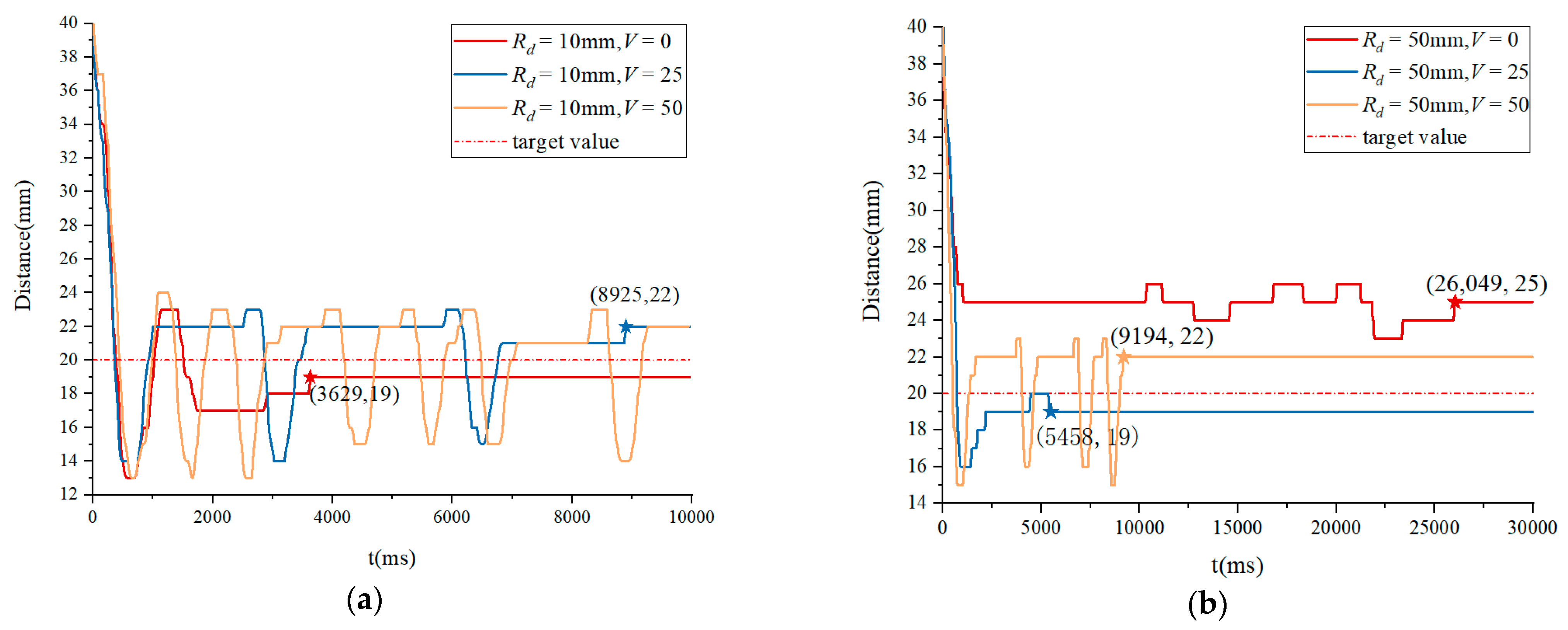
| 50 | 0 | 26,049 | 5 |
| 25 | 5458 | 1 | |
| 50 | 9194 | 2 | |
| Test Number | Actual Sowing Depth (mm) | Absolute Error of Seeding Depth (mm) | ||
|---|---|---|---|---|
| Soil Moisture Content < 20% | 20% < Soil Moisture Content < 35% | Soil Moisture Content > 35% | ||
| 1 | 18.2 | 8.6 | 1.5 | 1.57 ± 0.0785 |
| 2 | 18.9 | 9.1 | 1.1 | 1.03 ± 0.0515 |
| 3 | 18.1 | 10.8 | 1.2 | 1.30 ± 0.065 |
| 4 | 19.2 | 11.2 | 0.9 | 0.97 ± 0.0485 |
| 5 | 18.3 | 11.3 | 1.3 | 1.43 ± 0.0715 |
| 6 | 19.1 | 10.9 | 1.4 | 1.07 ± 0.0535 |
| 7 | 21.7 | 11.2 | 1.2 | 1.37 ± 0.0685 |
| Average | 19.07 | 10.44 | 1.24 | 1.25 ± 0.0625 |
| Index | No Adjustment | Automatic Adjustment |
|---|---|---|
| Sowing depth qualified rate (%) | 30.8 | 92.5 |
| Coefficient of variation of seeding depth (%) | 56.46 | 10.65 |
| Seeding depth stability coefficient (%) | 43.54 | 89.35 |
| Standard deviation of seeding depth (mm) | 3.41 | 1.11 |
Disclaimer/Publisher’s Note: The statements, opinions and data contained in all publications are solely those of the individual author(s) and contributor(s) and not of MDPI and/or the editor(s). MDPI and/or the editor(s) disclaim responsibility for any injury to people or property resulting from any ideas, methods, instructions or products referred to in the content. |
© 2024 by the authors. Licensee MDPI, Basel, Switzerland. This article is an open access article distributed under the terms and conditions of the Creative Commons Attribution (CC BY) license (https://creativecommons.org/licenses/by/4.0/).
Share and Cite
Xu, P.; Kou, J.; Wang, M.; Tu, T.; Chen, X.; Luo, J.; Hu, J.; Lei, X. Soil Moisture Detection and Linear Deceleration Control Strategy Enhancing Trenching Depth Precision and Stability for Rapeseed Sowing. Agriculture 2024, 14, 1717. https://doi.org/10.3390/agriculture14101717
Xu P, Kou J, Wang M, Tu T, Chen X, Luo J, Hu J, Lei X. Soil Moisture Detection and Linear Deceleration Control Strategy Enhancing Trenching Depth Precision and Stability for Rapeseed Sowing. Agriculture. 2024; 14(10):1717. https://doi.org/10.3390/agriculture14101717
Chicago/Turabian StyleXu, Peiru, Jianchuan Kou, Minghang Wang, Tianyu Tu, Xiaoling Chen, Jie Luo, Jianfeng Hu, and Xiaolong Lei. 2024. "Soil Moisture Detection and Linear Deceleration Control Strategy Enhancing Trenching Depth Precision and Stability for Rapeseed Sowing" Agriculture 14, no. 10: 1717. https://doi.org/10.3390/agriculture14101717