Article

Research and Experimentation on Sparse–Dense Interphase Curved-Tooth Sorghum Threshing Technology

1
College of Agricultural Engineering and Food Science, Shandong University of Technology, Zibo 255200, China
2
Shandong Shanli Risheng Information Technology Co., Ltd., Zibo 255000, China
*
Author to whom correspondence should be addressed.
Agriculture 2024, 14(10), 1722; https://doi.org/10.3390/agriculture14101722
Submission received: 10 September 2024 / Revised: 26 September 2024 / Accepted: 27 September 2024 / Published: 1 October 2024

Abstract

:
The high-speed development of the liquor industry brings sorghum demand, which is increasingly strong at the moment. Still, its harvesting mechanization level is low, and with the design of a longitudinal flow sparse and dense curved-teeth sorghum threshing technology, the harvester’s work quality is improved by the reduction of seed impurities. This article describes the working principle of the harvester, the overall distribution of threshing elements, and force analysis of the threshing aspects to determine the structure of the threshing elements. The orthogonal test was carried out, with a sparse–dense interphase threshing drum as the research object, selecting operating speed, threshing element bending angle, and threshing element mounting angle as the test factors, with the entrainment loss rate and the net threshing rate as the assessment indexes for the three-factor, three-level test, and the use of Design-Expert to establish a mathematical regression model between the factors and the two indicators, resulting in the following optimized parameters: when the operating speed is 1.0 m·s−1, the bending angle of the threshing element is 80°, and the mounting angle of the threshing element is 45°, the loss rate of entrainment is 1.89%, and the net threshing rate is 95.53%. The machine’s design indexes are in line with relevant national standards and can meet the demand for mechanized harvesting of sorghum.

1. Introduction

Sorghum is the fifth-largest grain crop in our country and has an important impact on feed and industrial production. Still, its mechanized production level is relatively low, especially since the level of harvest mechanization is only about 10%, which seriously affects the production efficiency of sorghum. In recent years, with the rural working population appearing by way of young adults, practitioners aging, and labor costs, sorghum through mechanized production, especially the mechanized harvesting of sorghum, has become the current urgent solution to solve the problem [1,2,3].
Foreign research on the mechanized harvesting of sorghum is limited, in terms of models, mainly focusing on modifying wheat harvesters to achieve the harvest of small grain crops [4,5,6,7,8,9]. For instance, the John Deere C120 model, using CTS technology—tangential flow threshing + single longitudinal axial flow separation technology—addresses the issue of low loss in high straw crops (sorghum), as well as the problem of a thick draft layer in the separation chamber caused by the large feeding volume during harvesting [10]. The C440 model, with tangential flow threshing + double longitudinal flow separation, has been developed, which effectively reduces the separation loss in the sorghum harvesting process. Although sorghum is categorized as the fifth most important crop in the country, it is a niche crop in the international arena overall, thus classified as a small grain crop. For example, Chaturvedi Shalini [11] et al. carried out a study on the adaptability of five different structural threshing devices for grain harvesting. PowarRV [12] et al. developed a peg-toothed threshing technology based on rounded heads to reduce the excessive fragmentation of the stalks and loss of seeds during the threshing process. Ryadnov A I [13] researched, based on the aforementioned studies, and developed a sorghum harvesting technology based on the principle of comb and brush threshing, which reduced losses in mechanized sorghum harvesting.
In 2008, Li Yaoming and his team [14] investigated the effects of two threshing technologies, namely, spike tooth and short-rasp-bar tooth, on the quality of rice harvesting, concluding that the short-rasp-bar tooth threshing technology had the advantages of reducing detritus content in the rejects and lowering power consumption. In 2011, the same team [15] investigated the effects of five types of threshing elements—rectangular-toothed plate, short-rasp-bar tooth, spike tooth, knife-shaped tooth, and trapezoidal tooth—on the performance of tangential-flow and longitudinal-flow rice separations, determining the optimal threshing separation combination. In 2017, Kang Dong [16] et al. investigated grain threshing technology based on a full grain bar and identified the optimal combination of operating parameters, reducing the unthreshed rate to 0.3%. In 2021, Li Xinping [17] et al. designed a longitudinal axial flow double flexible rolling and kneading threshing device for millet, which minimized grain seed breakage by incorporating a flexible rubber roller in the threshing drum. In 2023, Dr. Guo-Zhong Zhang [18] conducted an optimization study on the structural form of rod teeth, constructing a threshing device based on three structures: cylindrical rod teeth, elbow rod teeth, and closed bow teeth, and developed a mechanical model for the collision impact between rice and rod teeth.
In summary, there are relatively few studies on sorghum threshing technology at home and abroad. Although some scholars have researched mechanized threshing technology of small-grain seeds, the research on mechanized threshing technology of high-stalk and large-spike needs further study. With the increasing demand for sorghum brought on by the rapid development of the liquor industry, it is urgent to break through the efficient threshing technology in the process of mechanized sorghum harvesting. It is of great practical significance to establish the design theory of sorghum-efficient threshing devices and promote the popularization and application of sorghum harvesting mechanization technology. Promoting the popularization and application of sorghum harvest mechanization technology is of great practical significance. In this paper, a longitudinal flow sparse–dense interphase curved-tooth sorghum threshing technology is studied, which realizes the effect of low crushing of stalks and high-efficiency separation of seeds-stalks, and provides technical support for the research of sorghum harvesting equipment.

2. Materials and Methods

2.1. Composition and Working Principle of Sorghum Threshing Device

In China, sorghum harvesters face several challenges. To address these issues and consider the structural characteristics of the sorghum plant and its spike, as well as current research both domestically and internationally, a sorghum combined harvester was developed, as shown in Figure 1a. This harvester consists mainly of a cutting platform, chassis, cab, over-axle, threshing device, and the power system. During operation, the cutting platform cuts the sorghum stalks and conveys them to the transverse reverse conveyor. Subsequently, the sorghum passes through the bridge and into the threshing device, where the seeds are separated from the ears and cleaned. The seeds are then transferred to the seed bin, and the stalks are discharged from the machine. Due to the small seed size and high moisture content of sorghum stalks during the harvest period, the threshing device was enhanced to reduce seed loss and stalk entrainment, as illustrated in Figure 1b. The modified threshing device includes a feeding inlet, feeding cone, threshing drum, separating concave plate, and a top cover. In operation, sorghum is dragged by the blades on the feeding cone into the threshing chamber, which comprises the threshing drum, separating the concave plate, and top cover. The curved-tooth threshing elements on the drum impact and comb the spikes, separating the seeds. The stalks are then transported rearward by the coordinated action of the threshing elements and the top cover with the spiral deflector. Seeds are separated by gravity and centrifugal force through the concave plate, completing the separation process [5].

2.2. Threshing System Design

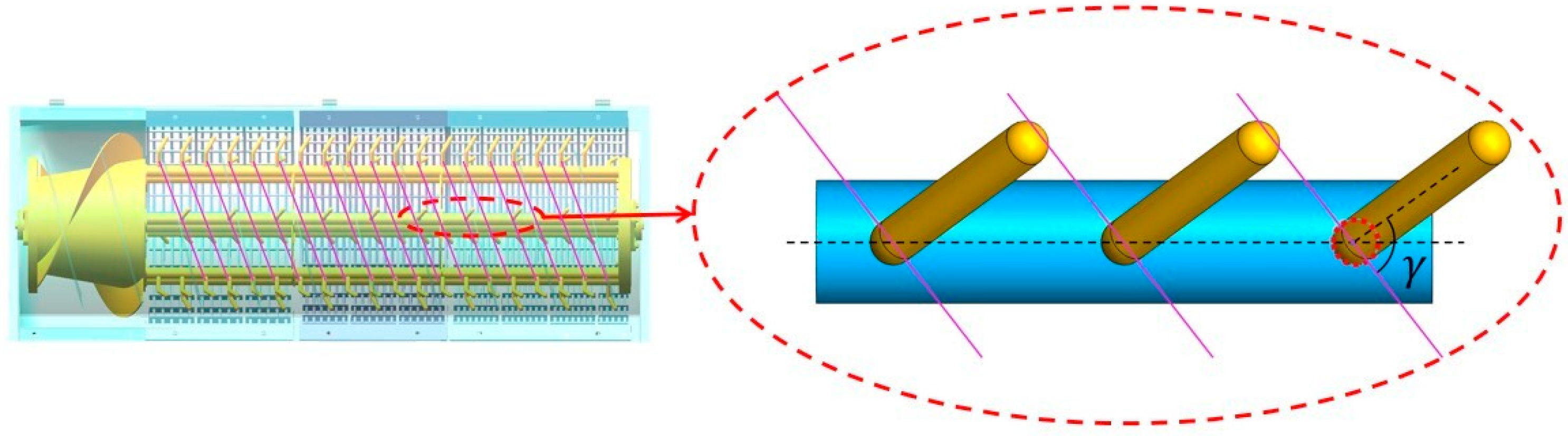
2.2.1. Overall Distribution of Threshing Elements

Although sorghum is the fifth largest seed crop in China, it is mostly grown in hilly and mountainous areas. Therefore, in order to improve the adaptability of the harvester to hilly and mountainous areas, this threshing drum adopts an open structure, which effectively reduces the weight of the threshing drum and improves the safety of the whole machine in the process of operation in complex terrain. To equalize the operating load and improve the smoothness and stability of the threshing product’s movement, the threshing element adopts multi-head spiral distribution. In order to reduce the excessive effect of the threshing element on the crop, the number of threshing elements is reduced, i.e., the sparse–dense tooth rod structure is adopted, under the condition of ensuring the threshing strength, reducing the number of times the threshing element acts on the crop through the threshing chamber and the degree of stalk crushing. At the same time, with the improvement of the distribution structure of sparse–dense threshing rod teeth. The fluffiness of the threshing object is increased, the probability of the seeds passing through the sorghum stalk is improved, and the entrainment loss of the threshing process is reduced, resulting in the distribution structure of the threshing elements shown in Figure 2.
l is a space reserved for the installation of threshing elements in front of and behind the threshing tines; a is the distance between the traces of the teeth; B1 is the tooth pitch of the threshing element, also known as the dense tooth spacing; B2 is the sparse tooth spacing; S is the tooth bar spacing; δ is the angle between the distribution helix of the threshing element and the axial direction; D is the diameter of the threshing drum with threshing elements.

2.2.2. Determination of Key Parameters of Threshing Drums

  • Determination of the number of threshing elements
Considering that the essence of sorghum threshing is to achieve the separation of seeds from the spike through the high-speed movement of the threshing element applying impact to the sorghum spike, its speed is primarily determined by the drum speed and diameter. The number of threshing elements can be expressed as follows:
z ( 1 β ) q 0.6 q d
Assuming that the diameter of the threshing drum is d, the weight ratio of seeds in the sorghum harvesting process is β, in this paper, the value is 0.36 [19]; the feeding volume is q, and the threshing capacity of each threshing element is qd.
From the formula, the number of threshing elements is 114.
  • Determination of the number of tooth plates
To equalize the operational load of the threshing drum and simplify the drum structure, the threshing element is generally mounted on the tooth plate, which is further fixed to the drum width plate. Thus, the tooth plates are typically evenly distributed on the drum surface/drum width plate. If the number of tooth plates (M) is excessive, while the threshing load on sorghum is increased, it also results in higher compaction density and crushing of the straw layer in the threshing chamber. This is not conducive to the threshing of seeds through the straw layer. To allow the straw sufficient space and time to regain its fluffy state after being subjected to the threshing load, this threshing drum is designed with six tooth plates (M = 6), evenly distributed around the drum circumference.
  • Determination of the number of helical heads
Given that the threshing element features a single-head spiral distribution, this may lead to a too-small tooth pitch, resulting in issues such as excessive straw crushing, clogging, and hanging grass. To increase the tooth pitch, in accordance with the recommendation of the Agricultural Machinery Design Manual, the number of spiral heads of the threshing element can be calculated as
K M 2
M is the number of tooth plates; K is the number of spiral heads. To enhance threshing efficiency, this threshing drum is designed with a three-head conical screw feeder head.
  • Determination of threshing drum diameter
Since the threshing element is welded to the threshing tine bar, assuming that the height of the threshing element is h, the tooth bar spacing is S, and the diameter of the drum without the threshing element is d, then
π d M S
i.e.,
d M S π
The diameter D of the threshing drum with threshing elements is
D = d + 2 h = M S π + 2 h
Here, d—the diameter of the drum without the threshing element, mm;
D—the threshing drum with threshing elements, mm;
S—the tooth bar spacing, mm;
M—the number of tooth plates;
h—the height of the threshing element, mm.
This threshing drum is designed with a threshing element height of 120 mm, and substituting the relevant data, it can be obtained that the diameter of this threshing drum is 620 mm.
  • Determination of threshing drum length
Since z threshing elements are uniformly distributed across K spirals, the number of threshing elements on each spiral is
n = z K
Considering that one end of the threshing drum connects to the feeding cone and the other end connects to the amplitude disk, the threshing element will reserve mounting space ∆l before and after the threshing tine bar. Let the distance between the traces of the teeth be a; thus, the length of the drum is given by
l = a ( n 1 ) + 2 Δ l = a ( z K 1 ) + 2 Δ l
Here, n—the number of threshing elements on each spiral;
z—total number of threshing elements;
K—the number of spiral heads;
l—the length of the drum, mm;
a—the distance between the traces of the teeth;
l—a space reserved for the installation of threshing elements in front of and behind the threshing tines, mm.
By substituting the relevant data, it can be obtained that the length of this threshing drum is 1880 mm.
  • Determination of threshing element spacing
Let the threshing element spacing be B1, the number of tine plates be M, the number of helix heads be K, and the distance between the traces of the teeth be a. The threshing element spacing B1 is given by
B 1 = M K a
As before, taking into account the seriousness of the stem breakage during the operation, the threshing drum adopts the structure of sparse–dense tooth bars, i.e., 3 dense teeth and 3 sparse teeth are adopted on the surface of the drum and arranged in a mutually spaced arrangement, as shown in Figure 3, in which the sparse tooth spacing B2 is
B 2 = ζ B 1
Here, ζ—the coefficient of increase in tooth spacing;
B1—the tooth pitch of the threshing element, also known as the dense tooth spacing, mm;
B2—the sparse tooth spacing, mm.
Here, ζ > 1. This machine chooses ζ as 2 based on experience.
Substituting the relevant data, it can be obtained that the threshing drum threshing element dense tooth spacing is 90 mm, and sparse tooth spacing is 180 mm.

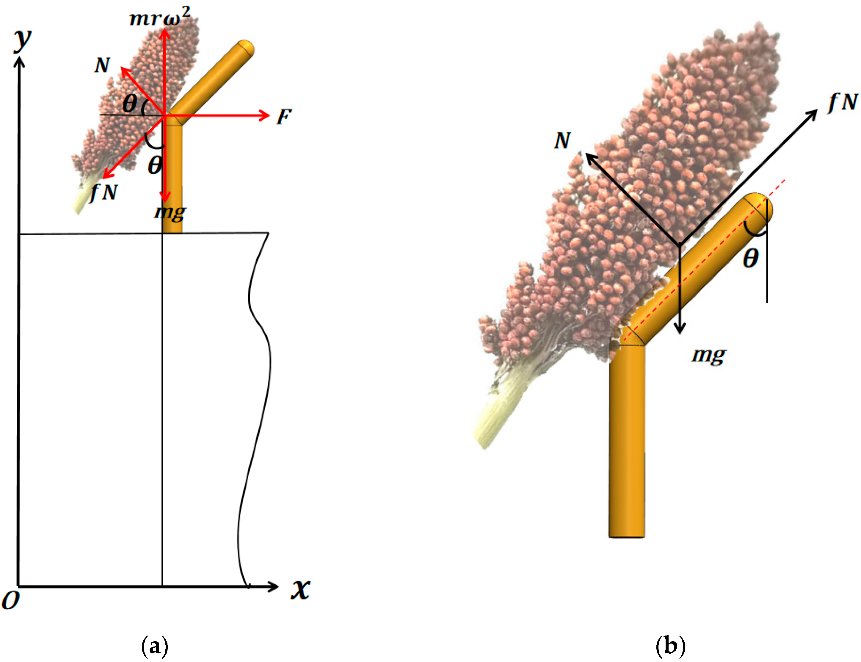
2.2.3. Determination of the Structure of the Threshing Element

Considering the straight rod teeth, although the structure is simple, it is easy for grass to hang during the threshing process, leading to serious problems with broken straw. To avoid excessive crushing of the stalks by the rod teeth during threshing, the straight rod teeth will have a higher linear speed, bending back at half their height [20]. This design ensures that the lower straight rod provides a sufficient threshing strength for the object, while the upper part bends to ensure a stable decline in the stalks. During threshing, the bent structure allows for gradually decreasing gaps, enabling the easier-to-detach parts of the sorghum spike to be removed first, while the more difficult parts follow. This effectively reduces the impact load of the threshing rod teeth on the sorghum, improves the smoothness of the draft grass sliding off the threshing element, increases the likelihood of the seeds passing through the layer of the draft grass, reduces the seed impurity rate, and enhances the operational quality of the harvester.
Additionally, when the threshing element reaches the top of the drum, the stalks are most likely to slide down due to gravity. The load on the threshing object at this point is analyzed, considering the gravitational force (mg) acting on it, the normal force N exerted by the threshing element, the centrifugal force (mrω2) from the circular motion under the influence of the threshing element, the axial force F pushing the threshing object to move along the axis, and the friction force (fN) acting when sliding down the threshing element. A coordinate system is established with the drum axis as the x-axis and vertical upward as the y-axis [21,22], as shown in Figure 4a.
Take x = 0 y = 0 there:
F = N cos θ + f N sin θ m r ω 2 + N sin θ = m g + f N cos θ
The sign that the threshing element does not entangle grass is N = 0, i.e.,
ω min g / r
Obviously, as the drum speed increases, it is beneficial to avoid grass entanglement or clogging of the threshing elements [23].
Secondly, because the threshing object’s distance r from the drum rotary center is constantly changing, the bending angle θ of this threshing element is variable, and the value of θ will be affected by the rotary radius r, conveying resistance F, friction coefficient f, and so on.
To ensure the stability of the threshing object sliding outward, consider the limit case, that is, when the drum speed is low, the threshing object located at the bend will not slide under the action of gravity. Then, the force analysis of the threshing object in the position under the static condition is carried out, as shown in Figure 4b. At this time, the force on the threshing object includes gravity (mg), friction (fN), and support force N, so there are the following forces:
m g cos θ = f N m g sin θ = N
A simplification of this is
tan θ = 1 / f ,
i.e.,
θ min A tan ( 1 / f )
In this machine, based on the de-splitting performance of sorghum, combined with the linear velocity required for rice and wheat threshing, the linear velocity of the threshing element of the sorghum threshing process was determined to be 15~20 m/s [24], according to the following formula [25,26]:
n = 60 V 1 π D ,
where n is the drum speed, r/min; V1 is the sorghum threshing line speed; the drum speed of this machine is 524~600 r/min.
Substituting the relevant data, it can be obtained that the range of values of the bending angle of the threshing element is 69.5 θ < 90 .

2.2.4. Mounting Angle of the Threshing Element

To reduce the entanglement of the threshing object on the threshing element, its end is designed as a bent structure. In order to reduce the excessive crushing of sorghum straw during the threshing process, the threshing tine bar adopts a normal distribution of the threshing element, and the spacing of the threshing element is increased. This may reduce the number of cyclic actions of the threshing element on the threshing object.
To compensate for the defects caused by this design, the mounting angle at the end perpendicular to the direction of movement of the threshing object (the angle between the threshing element and the direction of movement of the threshing object, expressed as γ, as shown in Figure 5) is obviously considered. Under normal circumstances, a completely perpendicular position is unfavorable for the sliding down of the threshing object from the threshing element, so, the angle is corrected to be less than the friction angle between the stalk and the threshing element.
γ = arctan S / a
The angle was finally determined to be 0° to 90°, i.e., γ = 0° to 90°.

2.3. Field Trials

2.3.1. Test Conditions and Methods

  • Test conditions
The trial was conducted on 27 September 2023, at the Agricultural Machinery Cooperative in Dongying City, Shandong Province, with a planted area of 200 acres and 28% moisture content of sorghum kernels at harvest time. The test equipment was a 4LZ-6.0ME(Q) full-feed tracked harvester with a homemade threshing drum for the test, as shown in Figure 6. The main test equipment included a 30 m tape measure, a moisture content tester, an electronic stopwatch, and an electronic scale.
  • Test methods
The designed drums were mounted on a 4LZ-6.0ME(Q) full-feed tracked harvester, designed to have a harvesting stroke of 50 m for each set of trials and a harvester cutting width of 2.1 m.
The entrainment loss rate was as follows: after the harvester stabilized, the material was obtained from the discharge opening, de-emulsified, and the entrainment loss seeds screened out were weighed and recorded as G1; the de-emulsified seeds in the seed bin were weighed and recorded as Gj.
S j = G 1 G 1 + G j × 100 % ,
where Sj is the entrainment loss rate, %.
The net threshing rate [27] was as follows: under the premise of ensuring the safe operation of the implement, a sample bag was hung at the rear of the harvester to collect the material discharged from the threshing drum and the cleaning fan, and at the end of each group of tests, respectively, for the sample bag and the material in the seed bin, the selection of uncleaned sorghum kernels was weighed and recorded as W1; the total mass of sorghum kernels during the test trip was recorded as Wt.
W t = M 1 F L ,
T t = 1 W 1 W t × 100 % ,
where Tt is the net threshing rate, %; M1 is the total sorghum seed mass per square meter, kg; F is the cutting width, m; and L is the operating distance.

2.3.2. Pilot Program

To obtain the best working parameters, and taking into account that sorghum is mostly planted in hilly and mountainous areas, the operating speed of the whole machine was low [28]. According to the structural parameters of the sorghum harvester of the current Agricultural Machinery Cooperative Society, the range of the operating speed was selected to be 0.8~1.2 m/s. Combined with the actual operational requirements, and according to the results of the previous theoretical design, the range of the bending angle of the threshing element was selected to be 70°~90°, the range of the mounting angle of the threshing element was selected to be 0°~90°. Referring to T/NJ 1117-2020 “Self-propelled Sorghum Combine Harvester”, the entrainment loss rate and threshing net rate were selected as evaluation standards.

2.3.3. Parameter Optimization and Validation Tests

Based on the above research, parameter optimization and verification experiments were carried out in the test to obtain the best level parameter combination. The regression equations of the entrainment loss rate and the threshing net rate were analyzed, and the constraints were selected according to the actual operation and theoretical conditions. The objectives and constraint functions are shown as follows:
min Y 1 X 1 , X 2 , X 3 max Y 2 X 1 , X 2 , X 3 s . t . 0.8 m s 1 X 1 1.2 m s 1 70 X 2 90 0 X 3 90

3. Results

3.1. Analysis of Orthogonal Test Results

To verify the influence of rod tooth spacing on the threshing quality of sorghum, the Box–Behnken response surface test method was used to carry out an orthogonal test. Combined with the results of theoretical analysis from the previous paper, the bending angle of the threshing element and the mounting angle of the threshing element, which affect the threshing quality, were selected as test factors. The entrainment loss rate and the net threshing rate were selected as the evaluation indexes of the test. A three-factor, three-level Box–Behnken response surface test was carried out. The coding of each factor is shown in Table 1. Each group of tests was repeated three times, with the average value taken as the test results. The test was conducted to evaluate the entrainment loss rate and the net threshing rate as the assessment index.
According to the response surface method in the Design-Expert 13 software for test program design and data analysis, the entrainment loss rate and the net threshing rate were used as the test assessment indexes. The total number of tests was 17 times, of which 12 groups were analyzed as the factor points and 5 groups as zero points. The zero point test was repeated several times to minimize the test error. The test program and results are shown in Table 2 (X1, X2, and X3 are the operating speed, threshing element bending angle, and threshing element mounting angle, respectively).
After the test data were processed by Design-Expert software, the variance of the entrainment loss rate and the net threshing rate were obtained, as shown in Table 3 and Table 4. The test results were analyzed by quadratic regression and were fitted by multiple regression to obtain the regression equations between the factors and indicators as follows:
Y1 = 1.92 + 0.9625X1 − 0.0687X2 + 3.48X3 + 0.005X1X2 + 0.105X1X3 − 0.0125X2X3 + 0.8518X12 + 0.7642X22 + 1.55X32
Y2 = 94.95 − 0.6362X1 + 1.56X2 − 0.2463X3 + 0.02X1X2 − 0.1825X1X3 + 0.245X2X3 − 4.51X12 − 0.1639X22 − 6.42X32
where X1—machine operating speed, m·s−1;
X2—threshing element bending angle, °;
X3—threshing element mounting angle,°;
Y1—the entrainment loss rate, %;
Y2—the net threshing rate, %.

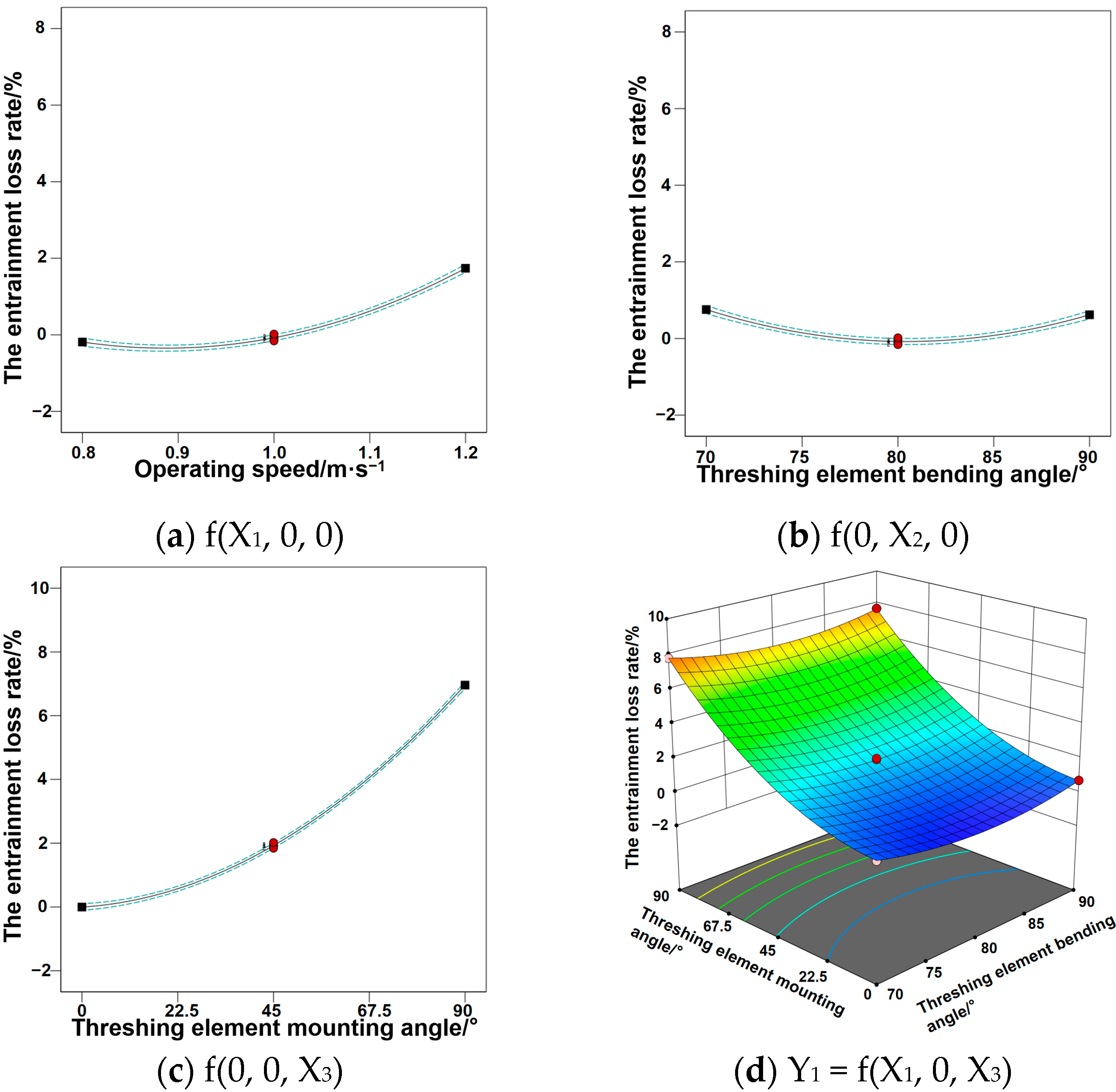
3.1.1. Analysis of Variance for the Entrainment Loss Rate

From the analysis of variance, it is clear that operating speed, threshing element bending angle, and threshing element mounting angle have different levels of influence on sorghum threshing quality. The analysis of the variance of the entrainment loss rate showed that the factors X1, X2, X3, X1X3, X12, X22, and X32 had a significant effect on the entrainment loss rate, while the other factors did not have a significant effect. The experimental model was significant (p < 0.01), with the lack-of-fit term of operating speed showing p < 0.0001, indicating that its effect on the entrainment loss rate was extremely significant. The lack-of-fit term of the bending angle of the threshing element was p < 0.0001, indicating that its effect on the entrainment loss rate was also extremely significant, while the lack-of-fit term of the mounting angle of the threshing element was p < 0.05, indicating a significant effect. The significance of each factor on the entrainment loss rate was X3 > X1 > X2 in descending order.

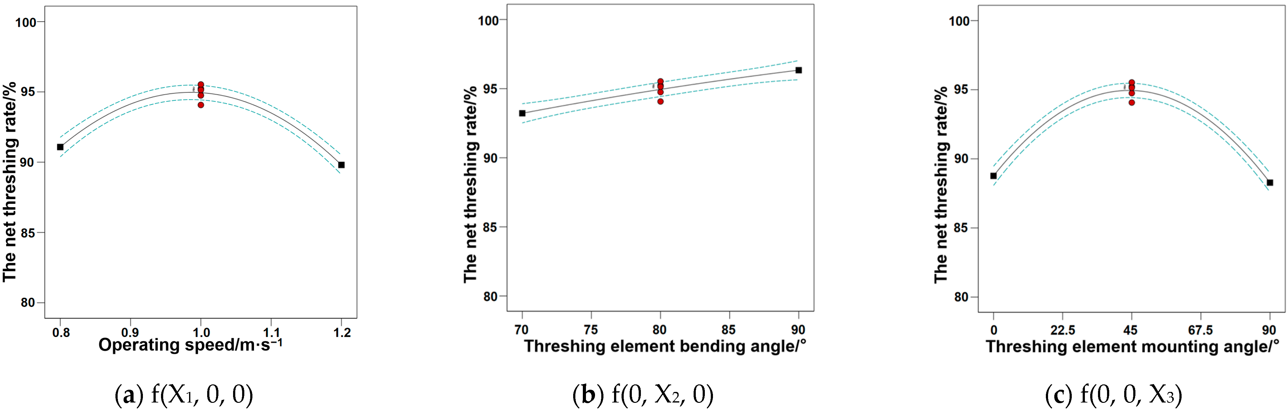
3.1.2. Analysis of Variance for the Net Threshing Rate

From the analysis of variance, it can be seen that the operating speed, threshing element bending angle, and threshing element mounting angle had different influences on the quality of sorghum threshing. The analysis of the variance of the net threshing rate showed that the influencing factors X1, X2, X12, and X32 had a significant effect on the net threshing rate, while the other factors did not have a significant effect. The experimental model was significant (p < 0.01), in which the lack-of-fit term of the bending angle of the threshing element (p < 0.0001) indicated that its effect on the net threshing rate was extremely significant, and the lack-of-fit term of the operating speed (p < 0.01) indicated that its effect on the net threshing rate was significant. The significance of each factor on the net threshing rate was X2 > X1 > X3 in descending order.
Based on the experimental results, the entrainment loss rate and threshing response surface plots were constructed, as shown in Figure 7 and Figure 8. It can be seen that during the harvesting of sorghum plants, the faster the operating speed of the machine, the higher the feeding volume, which is more likely to cause blockages. When the operating speed is slow, resulting in a higher net threshing rate and less entrainment loss, as shown in Figure 7a and Figure 8a. The reason for such changes can be speculated to be that the feeding volume is small, and the material layer in the threshing chamber is thin; however, the straw is severely broken, which significantly impacts subsequent cleaning. When the operating speed is too high, the feeding volume is too large, causing the entrainment loss rate to rise and the net threshing rate to decrease. The reason for such changes can be speculated to be that the thickness of the material layer in the threshing chamber increases, which results in a large change in the threshing load on the spike part of the sorghum. The difficulty of the threshed seeds passes through the straw layer increases. The optimal range of the operating speed is 0.9~1.1 m/s.
The force analysis of the crop in the drum on the threshing element shows that the size of the bending angle of the threshing element affects the force experienced by the crop in the threshing drum. As the angle θ increases, the net threshing rate of sorghum grain increases accordingly, and the rate of entrainment loss remains almost constant, as shown in Figure 7b,d and Figure 8b. The reason for such changes can be speculated to be that the impact load of the threshing bar teeth on the sorghum is effectively reduced, improving the smoothness of the crop sliding off the threshing element, increasing the percentage of intact stalks, and enhancing the likelihood of the seeds traversing the crop layer. This is conducive to improving the net threshing rate of sorghum kernels, and the entrainment loss rate of the kernels increases accordingly. The optimal range of the threshing element bending angle is 80~85°.
The mounting angle of the threshing element affects the contact area between the crop and the threshing element in the threshing drum. As the mounting angle increases, the entrainment loss rate increases accordingly, but the net threshing rate shows a tendency of increasing and then decreasing, as shown in Figure 7c,d and Figure 8c. The reason for such changes can be speculated to be that the contact area between the sorghum spike and the threshing element increases, improving threshing efficiency while reducing contact stress, reducing crushing, so that the threshing is not crushed, and there are not too many broken stalks and broken branches. However, if the mounting angle of the threshing element is too large, it will still break too much straw, resulting in a decrease in the rate of threshing. The optimal range of the threshing element mounting angle is 22.5~45°.

3.2. Parameter Optimization and Validation Test Results

Optimization of the above Function (20) yields the following results: when the operating speed is 1.0 m·s−1, the bending angle of the threshing element is 80°, and the mounting angle of the threshing element is 45°, the rate of entrainment loss is 1.89%, and the rate of net threshing is 95.53% [29].
Under the optimal level of parameter combinations for the entrainment loss rate and net threshing rate, tests were conducted to verify the results and eliminate random errors. The test was repeated five times, the average of the test results was taken, and the results show that the entrainment loss rate is 1.92% and the net threshing rate is 94.97%. The predicted value error for the optimal parameter combinations is less than 5%, indicating that the optimization result is credible.

4. Discussion

The material used in this test was sorghum with a moisture content of 28%, which presents some limitations [30]. In this paper, the structure of the threshing element with straight rod teeth bent backward at half of the height was determined, but it is not necessarily the optimal structure. In the future, it is essential to bend the teeth at different heights to validate the analysis results and obtain the optimal bent tooth structure.

5. Conclusions

  • We developed end-bending rod teeth for a sparse-dense threshing drum, determined the overall distribution structure of the threshing element, and identified the key parameters of the threshing drum. We established the structure of the threshing element with straight rod teeth bent backward at half of their height, setting the bending angle of the threshing element in the range of 69.5° to 90° and the mounting angle of the threshing element in the range of 0° to 90°. This effectively reduces the impact load of the threshing rod teeth on the sorghum, improves the smoothness of the crop sliding off the threshing element, enhances the integrity of the stalk, and improves the conditions for the seeds to cross the draft layer, facilitating the separation of the threshed seeds from the draft grass, thereby helping to reduce the impurity rate of the seeds.
  • Orthogonal tests were carried out using the sparse-dense interphase threshing drum as the research object, selecting operating speed, bending angle of the threshing element, and mounting angle of the threshing element as test factors, with the entrainment loss rate and the net threshing rate as assessment indicators for a three-factor, three-level test. The optimal parameter range was derived as follows: an operating speed of 0.9~1.1 m/s, an element bending angle of 80~85°, and an element mounting angle of 22.5~45°.
  • Design-export was used to establish a mathematical regression model between the factors and the two indicators, resulting in the following optimized parameters: when the operating speed is 1.0 m·s−1, the bending angle of the threshing element is 80°, and the mounting angle of the threshing element is 45°, the entrainment loss rate is 1.89%, and the net threshing rate is 95.53%.

Author Contributions

Conceptualization, J.M. and D.G.; methodology, J.M. and D.G.; software, J.M.; validation, J.M., D.G., and Q.H.; formal analysis, J.M. and D.G.; investigation, Q.H., L.N. (Lin Niu), and Y.C.; resources, Q.H., D.G., Y.C., and L.N. (Lei Ni); data curation, Q.Y. and J.Y.; writing—original draft preparation, J.M.; writing—review and editing, D.G.; visualization, Q.H. and J.Y.; supervision, D.G., Y.C., and J.Y.; project administration, L.N. (Lin Niu), Q.Y., and Y.W.; funding acquisition, D.G. All authors have read and agreed to the published version of the manuscript.

Funding

This research was funded by the National Key R&D Program of China, grant number 2021YFD2000502, the Natural Science Foundation of Shandong Province, grant number ZR2022ME064, the Modern Agricultural Industrial System of Shandong Province, grant number SDAIT-02-12, and the development of sorghum harvesting machine in hilly and mountainous areas transversal project, grant number 2221831.

Institutional Review Board Statement

Not applicable.

Data Availability Statement

The data presented in this study are available in the article.

Conflicts of Interest

Author Lei Ni was employed by the company Shandong Shanli Risheng Information Technology Co., Ltd. The remaining authors declare that the research was conducted in the absence of any commercial or financial relationships that could be construed as a potential conflict of interest.

References

  1. Nagy, R.; Kun-Nemes, A.; Szőllősi, E.; Molnár, P.B.; Cziáky, Z.; Murányi, E.; Sipos, P.; Remenyik, J. Physiological potential of different Sorghum bicolor varieties depending on their bioactive characteristics and antioxidant potential as well as different extraction methods. Heliyon 2024, 10, e35807. [Google Scholar] [CrossRef] [PubMed]
  2. Cao, W.; Sun, C.; Liu, R.; Yin, R.; Wu, X. Comparison of the effects of five pretreatment methods on enhancing the enzymatic digestibility and ethanol production from sweet sorghum bagasse. Bioresour. Technol. 2012, 111, 215–221. [Google Scholar] [CrossRef] [PubMed]
  3. Feng, Y.; Qiu, S.; Yuan, X.; Cui, Q.; Wu, C. Tensile Characteristics of Sorghum Spikelet and Grains. Agric. Eng. 2021, 11, 119–124. [Google Scholar]
  4. Wang, L.; Hu, C.; Guo, W.; He, X.; Wang, X.; Jian, J.; Hou, S. The effects of moisture content and loading orientation on some physical andmechanical properties of tiger nut. Am. J. Biochem. Biotechnol. 2021, 17, 109–117. [Google Scholar] [CrossRef]
  5. He, Q.; Wang, Q.; Geng, D.; Li, D.; Niu, L.; Ma, J.; Zhang, C.; Ming, J.; Ni, L. Design and Experiment of Grain Lifter for Sorghum Harvester. Appl. Sci. 2023, 13, 13168. [Google Scholar] [CrossRef]
  6. Wu, L.; Chen, D.; Xu, X.; Wu, Y. Experimental Design and Validation of an Adjustable Straw Guide Structure for a Grain Combine Harvester Thresher Based on a Material Movement Model. Appl. Sci. 2023, 13, 8476. [Google Scholar] [CrossRef]
  7. Astanakulov, K.D.; Umirov, A.T.; Sultanbekova, P.S.; Alpamyssova, G.B. Determination of working indicators of New Holland TS-5060 combine for soy bean harvesting. IOP Conf. Ser. Earth Environ. Sci. 2021, 839, 052048. [Google Scholar] [CrossRef]
  8. GRAIN. IMC completes harvesting winter wheat, threshing 122,000 tonnes. In Interfax: Russia & CIS Food & Agriculture Weekly; Interfax: Moscow, Russia, 2021. [Google Scholar]
  9. Rogovskii, I.L.; Martiniuk, D.I.; Voinash, S.A.; Luchinovich, A.A.; Sokolova, V.A.; Ivanov, A.M.; Churakov, A.V. Modeling the throughput capacity of threshing-separating apparatus of grain harvester’s combines. IOP Conf. Ser. Earth Environ. Sci. 2021, 677, 042098. [Google Scholar] [CrossRef]
  10. Camolese, H.; Baio, F.; Alves, C. Quantitative and Qualitative Losses from Harvesters with Radial and Axial Threshing Systems Depending on Grain Moisture. Rev. Bras. Eng. Biossist. 2015, 9, 21–29. [Google Scholar]
  11. Chaturvedi, S.; Rathore, F.; Pandey, S. A Modification and development of threshing unit for minor millets. Bhartiya Krishi Anusandhan Patrika 2018, 33, 195–199. [Google Scholar] [CrossRef]
  12. Powar, R.V.; Aware, V.V.; Shahare, P.U. Optimizing operational parameters of finger millet threshing drum using RSM. J. Food Sci. Technol. 2019, 56, 3481–3491. [Google Scholar] [CrossRef] [PubMed]
  13. Ryadnov, A.I.; Fedorova, O.A.; Sharipov, R.V.; Baril, V.A. Sorghum harvester work quality assessment. Conf. Ser. Earth Environ. Sci. 2021, 786, 012030. [Google Scholar] [CrossRef]
  14. Tang, Z.; Li, Y.; Xu, L.; Zhao, Z.; Li, H. Effects of different threshing components on grain threshing and separating by tangential-axial test device. Trans. CSAE 2011, 27, 93–97. [Google Scholar]
  15. Li, Y.; Li, H.; Xu, L. Comparative experiments on threshing performance between short-rasp-bar tooth cylinder and spike tooth cylinder. Trans. CSAE 2008, 24, 139–142. [Google Scholar]
  16. Kang, D.; Wu, C.; Liang, S.; Tang, Q. Design and test of threshing device of millet combine harvester. J. China Agric. Univ. 2017, 22, 135–143. [Google Scholar]
  17. Li, X.; Wang, W.; Zhao, G.; Sun, C.; Hu, P.; Ji, J. Design and Experiment of Longitudinal Axial Flow Double Flexible Rolling and Kneading Threshing Device for Millet. Trans. Chin. Soc. Agric. Mach. 2021, 52, 113–123. [Google Scholar]
  18. Wang, F.; Liu, Y.; Li, Y.; Ji, K. Research and Experiment on Variable-Diameter Threshing Drum with Movable Radial Plates for Combine Harvester. Agriculture 2023, 13, 1487. [Google Scholar] [CrossRef]
  19. Pan, C.B.; Zhang, J.L.; Wang, G.M.; Wang, C.; Zhong, N.Q.; Pan, Z.P. Botanical characteristics and biomass of hongyingzi sorghum. Tillage Cultiv. 2022, 42, 37–41. [Google Scholar]
  20. Liu, W.; Zhou, Y.; Xu, H.; Fu, J.; Zhang, N.; Xie, G.; Zhang, G. Optimization and experiments of the drum longitudinal axial threshing cylinder with rod tooth for rice. Trans. Chin. Soc. Agric. Eng. 2023, 39, 34–45. [Google Scholar]
  21. Barnwal, P.; Kadam, D.M.; Singh, K. Influence of moisture content on physical properties of maize. Int. Agrophys. 2012, 26, 331–334. [Google Scholar] [CrossRef]
  22. Khazaei, J.; Shahbazi, F.; Massah, J. Evaluation and modeling of physical and physiological damage to wheat seeds under successive impact loadings: Mathematical and neural networks modeling. Crop. Sci. 2008, 48, 1532–1544. [Google Scholar] [CrossRef]
  23. Jin, C.; Kang, Y.; Guo, H.; Wang, T.; Yin, X. Experimental research on the influence of threshing roller structures on the quality of mechanically-harvested soybeans. Trans. Chin. Soc. Agric. Eng. 2021, 37, 49–58. [Google Scholar]
  24. Duanyang, G.; Daolin, Z. Threshing device. In New Agricultural Mechanics, 1st ed.; Duanyang, G., Daolin, Z., Eds.; National Defense Industry Press: Beijing, China, 2011; Volume 11, pp. 267–268. [Google Scholar]
  25. Teng, Y.J.; Chen, Y.P.; Jin, C.Q.; Yin, X. Design and test on the type of spiral cylinder⁃segmented concave threshing system the type of spiral cylinder-segmented concave threshing system. In Proceedings of the 2019 ASABE Annual International Meeting 1900700, Boston, MA, USA, 7–10 July 2019. [Google Scholar]
  26. Liang, S.N.; Jin, C.Q.; Zhang, F.F.; Kang, D.; Hu, M.J. Design and experiment of 4LZG-3.0 millet combine harvester. Trans. Chin. Soc. Agric. Eng. 2015, 31, 31–38. [Google Scholar]
  27. Sandhiya, D.P.; Eindhuja, M.; Giridharan, K.; Kamali, K.; Sakthi, V.S. Design and Development of Sesame Threshing Unit. Sci. Hub Appl. Res. Eng. Inf. Technol. 2022, 2, 19–26. [Google Scholar]
  28. Gurracho, B.A.; Bedie, A.F.; Tola, Y.B.; Habtegabriel, S.A.; Forsio, S.F. Design, Manufacturing and Testing of Composite Type Cylinder Sorghum Thresher. East Afr. J. Sci. 2024, 18, 1–14. [Google Scholar] [CrossRef]
  29. Xin, P.L.; Wan, T.Z.; Wen, Z.W.; Yu, H. Design and Test of Longitudinal Axial Flow Staggered Millet Flexible Threshing Device. Agriculture 2022, 12, 1179. [Google Scholar] [CrossRef]
  30. Fulani, A.U.; Kuje, J.Y.; Mohammed, B.I. Effect of Moisture Content on Performance of a Locally Fabricated Cowpea Thresher. J. Eng. Appl. Sci. 2013, 5, 1–15. [Google Scholar]
Figure 1. (a) Combined sorghum harvester; (b) structure of threshing device of sorghum harvester.
Agriculture 14 01722 g001
Figure 2. Expanded view of the distribution of threshing elements on the drum surface.
Agriculture 14 01722 g002
Figure 3. Sparse–dense rod tooth threshing drums.
Agriculture 14 01722 g003
Figure 4. (a) Force analysis of threshing object; (b) force analysis of threshing objects under static conditions.
Agriculture 14 01722 g004
Figure 5. Top view of partially toothed rod.
Agriculture 14 01722 g005
Figure 6. Test prototype.
Agriculture 14 01722 g006
Figure 7. Effect of factor interaction on the rate of entrainment loss.
Agriculture 14 01722 g007
Figure 8. Effect of factor interactions on the rate of net threshing.
Agriculture 14 01722 g008
Table 1. Orthogonal test factors and levels.
LevelExperimental Factors
Operating Speed
X1/m·s−1
Threshing Element Bending Angle
X2
Threshing Element Mounting Angle
X3
10.8700
21.08045
31.29090
Table 2. Experimental program and results.
No. X1X2X3The Entrainment Loss Rate
Y1/%
The Net Threshing Rate
Y2/%
10.870452.6289.21
21.290454.4791.37
31.09000.7189.73
41.080451.9294.75
51.270454.6388.18
61.28001.6783.84
70.88000.0585.03
80.880906.7884.56
91.070907.8086.49
101.080452.0295.24
111.07000.7987.13
121.080451.9594.07
131.280908.8282.64
141.080451.8495.14
151.090907.6790.07
160.890452.4492.32
171.080451.8995.53
Table 3. Analysis of variance for the entrainment loss rate.
Source of VariationSum of SquaresDegrees of Freedom Mean SquareFp
mold121.71913.522409.09<0.0001 **
X17.4117.411320.24<0.0001 **
X20.037810.03786.740.0357 *
X396.95196.9517,271.15<0.0001 **
X1X20.000110.00010.01780.8976
X1X30.044110.04417.860.0264 *
X2X30.000610.00060.11130.7484
X123.0513.05544.15<0.0001 **
X222.4612.46438.09<0.0001 **
X3210.17110.171811.92<0.0001 **
Residual0.039370.0056
Incoherent0.021230.00711.560.3308
Pure error0.018140.0045
Inaccuracies121.7516
Note: ** Indicates highly significant (p < 0.01) and * indicates significant (p < 0.05).
Table 4. Analysis of variance for the net threshing rate.
Source of VariationSum of SquaresDegrees of Freedom Mean SquareFp
mold298.86933.21139.44<0.0001 **
X13.2413.2413.600.0078 **
X219.47119.4781.76<0.0001 **
X30.485110.48512.040.1965
X1X20.001610.00160.00670.9370
X1X30.133210.13320.55950.4789
X2X30.240110.24011.010.3488
X1285.52185.52359.12<0.0001 **
X220.120610.12060.50650.4997
X32173.641173.64729.16<0.0001 **
Residual1.6770.2381
Incoherent0.396030.13200.41550.7518
Pure error1.2740.3177
Inaccuracies300.5316
Note: ** Indicates highly significant (p < 0.01).
Disclaimer/Publisher’s Note: The statements, opinions and data contained in all publications are solely those of the individual author(s) and contributor(s) and not of MDPI and/or the editor(s). MDPI and/or the editor(s) disclaim responsibility for any injury to people or property resulting from any ideas, methods, instructions or products referred to in the content.

