Article

Design and Experiment of a Crawler-Type Harvester for Red Cluster Peppers in Hilly and Mountainous Regions

College of Mechanical and Electrical Engineering, Shihezi University, Shihezi 832003, China
*
Author to whom correspondence should be addressed.
Agriculture 2024, 14(10), 1742; https://doi.org/10.3390/agriculture14101742 (registering DOI)
Submission received: 2 September 2024 / Revised: 18 September 2024 / Accepted: 1 October 2024 / Published: 2 October 2024
(This article belongs to the Section Agricultural Technology)

Abstract

:
To improve the mechanization levels of red cluster pepper harvesting in hilly and mountainous regions of southwest China, a crawler-type harvester is developed to suit the local planting and growth characteristics of red cluster pepper and to facilitate mechanized picking, conveying, and collecting processes. The design, supported by theoretical calculations and structural analysis, includes detailed studies of the picking, conveying, and collecting mechanisms, as well as the hydraulic system. Factors affecting picking efficiency were identified. ADAMS simulation was used to determine the optimum rotational speed range for the spring-tooth roller by analyzing its trajectory. A prototype was then built and field tested with forward speed and the spring-tooth roller’s rotational speed as variables to assess impurity, damage, loss, and hanging rates. Data from these tests were analyzed using Design Expert software, which created a mathematical model relating the test indices to the two variables. Optimum parameters were identified, resulting in a harvester configuration that achieved an average productivity of 0.21 ha·h−1 at a forward speed of 1.75 m·s−1 and a roller rotational speed of 181 r·min−1. The impurity rate was 26.7%, the loss rate was 6.1%, the damage rate was 2.3%, and the hanging rate was 4.2%, conforming to the industry standard DG/T 114-2019. This research provides a viable solution for mechanized harvesting of red cluster pepper in hilly and mountainous regions with small planting plots.

1. Introduction

China is one of the world’s leading producers and consumers of pepper, with extensive production areas. Each production area has distinctive, locally advantageous varieties that offer significant potential for industrial growth [1,2]. By 2023, China’s pepper cultivation area had expanded to 2.23 million hm2, yielding approximately 64 million tons. The southwest region, comprising Yunnan, Guiyang, and Sichuan, is the largest pepper production area in China, accounting for 30.23% of the national area [3,4]. Guizhou Province stands out as a leader in the pepper industry, accounting for 16.21% of the national area under cultivation [5,6]. It is recognized as the key region of the national pepper industry. In the Southwest, pepper is grown mainly on hilly mountains and dry slopes, which are characterized by limited planting space, difficult logistics, and regions unfavorable for extensive mechanical operations [7]. The low level of mechanization in cultivation, planting, and harvesting increases production costs. As a result, the industrial scale remains modest, and the market framework is underdeveloped. Red cluster pepper, grown in the southwest mountainous regions, has distinct local characteristics. During mechanical harvesting, the equipment often collects both stems and fruits, resulting in a high level of impurities, which requires considerable human labor and resources. Therefore, there is an urgent need for small red cluster pepper harvesters that can be adapted to hilly and mountainous regions.
International research on pepper harvesters began in the 1960s, with major contributions from American companies such as McClendon, Pikrite, and OXBO [8]. Although these companies pioneered and advanced pepper harvesting technology, the high cost of importing such machinery has hindered its widespread adoption in domestic markets, particularly in terms of cost-effectiveness. In China, research into mechanized pepper harvesting began later. Chen Yongcheng and his team [9,10,11,12] were among the early pioneers, focusing on cultivation and harvesting practices in Xinjiang. They designed a spring-toothed roller harvester and developed a prototype, thus contributing to the mechanization of pepper harvesting. However, due to the early stage of the research, the performance of the first prototype was suboptimal in terms of harvesting efficiency and pepper damage reduction. To improve picking performance, Duan investigated the mechanical characteristics and picking damage mechanism of plate pepper and pointed out that the damage to pepper was mainly due to the impact effect of the tip and side of the spring tooth on the pepper fruit [13]. Wang conducted more in-depth research on the collision damage mechanism of pod peppers with different moisture content, and the reliability of theoretical results was verified by high-speed camera technology and a crash test bench [14]. Du used the discrete element method to calibrate pepper parameters; DEM calibration of pepper could be instructive for the calibration of other irregular crops [15] and improved the understanding of the interaction between pepper and the harvester. Deng designed a flexible end-effector based on bionic features for picking angular peppers [16]. Some researchers optimized the parameters of a comb-picking device through bench tests using selected Indian chili varieties [17]. In line with the trend towards intelligent agricultural machinery, Ayan Paul explored a method for detecting peppers using the YOLO algorithm, concluding that the YOLOv8s model achieved the best detection results [18]. Zhang proposed a method based on CEEMDAN-KPCA-SVM to identify the load state of the drum based on the torque signal of the drum spindle, providing valuable insights into loss rates and mechanical damage caused by complex working conditions in pepper harvesting [19]. Some researchers have investigated double-helix picking mechanisms for pepper, inspired by the helix-to-roller mechanism used in maize harvesters [20,21,22]. Although theoretically promising with a high net harvest rate, practical challenges include high impurity content, limited applicability to row-to-row harvesting, and poor adaptability to varying pepper row spacing, which limits their real-world application. Currently, the large pepper harvesters available on the market are mainly designed for large areas of flat land and are not sufficiently adaptable to mountainous or hilly regions. Consequently, some researchers have shifted their focus to the development of crawler-type pepper harvesters suitable for mountainous regions [23,24,25,26]. These efforts include hydraulic system design, vibration analysis, and modeling and simulation. However, most of these studies remain at the theoretical modeling and simulation stage and require further validation through practical applications. While numerous studies have investigated agricultural implements for hilly and mountainous areas [27,28,29,30,31,32,33,34], there is still a lack of research on small pepper harvesters tailored for small to medium plots in the hilly regions of southwest China.
To address the problems associated with the concentrated ripening phase of red pepper and the specific operational requirements of small plots in the mountainous areas of southwest China, this study focuses on optimizing the design of a red cluster pepper harvester. In addition, this study aims to develop a harvester suitable for small to medium-sized plots designed to perform picking, conveying, and collecting operations in an integrated process and to provide a technical basis for subsequent studies in the field of pepper harvesting machinery. The main contributions of this paper are as follows:
  • Kinematics of spring tooth is conducted during the harvesting of red cluster peppers, considering their cultivation patterns and intrinsic physical properties. The trajectory of the spring tooth was simulated using ADAMS 2020 software to determine the optimal speed range for efficient operation. A force analysis is performed on the spring-tooth structure to determine the optimal design and arrangement for maximum performance.
  • A two-stage conveying mechanism is designed, coupled with an integrated collecting system. The motion phases of the conveying process are analyzed to determine parameters that would effectively mitigate impact damage and prevent the peppers from rolling. Design and calculation of the structure and operating parameters of the conveying device.
  • Performance-affecting factors were systematically optimized through field orthogonal tests combined with a comprehensive scoring method, leading to the identification of the optimal parameter combination.
The rest of this paper is organized as follows: Section 2 provides a detailed introduction to the design of harvesters, including picking, conveying, and collecting devices. Section 3 presents the experimental results and discussion. Section 4 provides further discussion and prospects for future work. Section 5 concludes the paper.

2. Materials and Methods

2.1. Structure of the Whole Harvester and Working Principle

2.1.1. Cultivation Techniques and Mechanized Harvesting Criteria

This study focuses on the Guizhou red cluster pepper, concentrating on the morphological and agronomic characteristics of this plant. The pepper fruit clusters are mainly found at the terminal ends of the branches, accompanied by leaves ranging from 40 to 70 mm in length. The minimum height of the fruit cluster (L1) is 350 mm, while the total height of the plant (L2) varies between 500 and 900 mm. The fruits themselves vary in length from 70 to 150 mm and in diameter from 30 to 60 mm. When ripe, the fruits change color to either red or purple. Adequate water management is essential in the cultivation of red cluster peppers and requires the use of shallow ridges to prevent waterlogging, which can be detrimental to plant growth. The selected test variety is the “No.8” red cluster pepper (Zunyi City, Guizhou, China) [35], and its planting pattern is shown in Figure 1. Key agronomic parameters include row spacing (l1) between 350 and 450 mm, plant spacing (l2) between 212 and 347 mm, ridge width (D) of 600 mm, ridge height (h) between 70 and 100 mm, and ridge trench width (d) between 300 and 500 mm.
Mechanized pepper harvesting involves several key stages, including picking, conveying, and collecting, which are all integrated into a single operation to streamline the harvesting process. This integration significantly improves both the efficiency and quality of the harvest. The harvester is equipped with a crawler chassis to meet the challenges of the southwest region, which is characterized by uneven ground and frequent hillside planting on small, steeply sloping plots, as well as the agricultural practice of double planting for red cluster pepper. In addition, the harvester uses a double-row, single-ridge pattern to increase adaptability and stability during harvesting. The harvester’s design specifications are specifically adapted to pepper harvesting conditions, with a working width of 1090 mm, a span of 1100 mm, and a crawler width of less than 400 mm.

2.1.2. Overall Structure and Working Principles of the Harvester

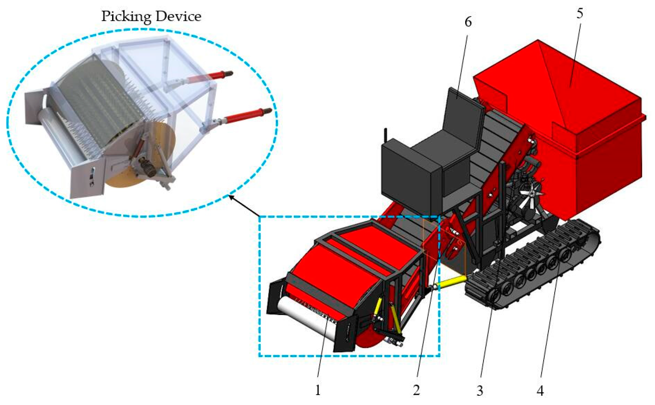
Based on the discussed cultivation patterns and harvesting requirements, Figure 2 illustrates the overall structure of the harvester, which includes a picking device, first-level and second-level conveying devices, a collecting device, and a crawler chassis.
During operation, the harvester initially uses the lifting hydraulic cylinder to adjust the picking device’s height, aligning the crop pressing roller with the densely clustered peppers and the rows of peppers. The harvester moves forward, causing the pepper plants to be tilted at an angle to the ground by the crop-pressing roller. This position allows the plants to enter the roller smoothly, minimizing impact. The spring-tooth roller picks up the peppers, which are then conveyed to the next device. First-level and second-level conveying devices transfer the peppers to the collecting device, completing the harvesting process. The main technical parameters are listed in Table 1.

2.2. Design of the Picking Device

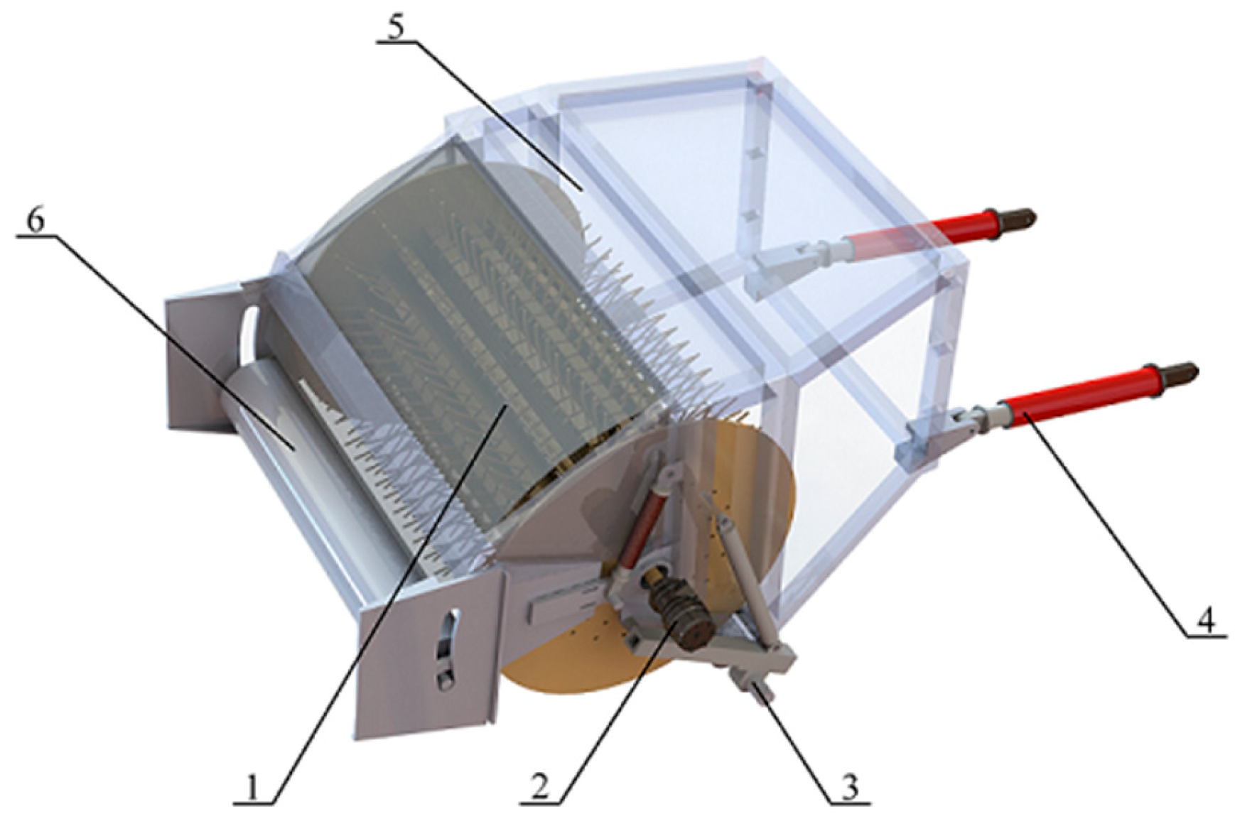
The picking device of the harvester consists of a spring-tooth roller, a hydraulic motor for the roller, a ground wheel, two hydraulic lifting cylinders, a cover plate, and a pressing roller. The specific structure is shown in Figure 3.
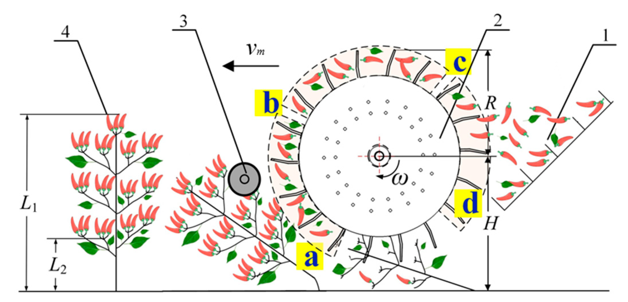
The picking process of the spring-tooth roller (Figure 4) can be divided into four stages. Combing stage (a–b): red cluster peppers enter the roller and come into contact with the spring tooth, which brushes them off the plants at high speed. Carrying stage (b–c): once detached, red cluster peppers are carried upwards and then backwards by the spring tooth. Throwing stage (c–d): by means of centrifugal force, red cluster peppers are thrown onto the conveyor belt, completing the picking process. Idle return stage (d–a): the spring-tooth roller rotates back to its starting point, preparing for another cycle without the spring-tooth contacting the peppers.

2.2.1. Determination of the Spring-Tooth Roller’s Radius

The spring-tooth roller of the harvester is composed of spring-tooth, spring-tooth boards, bearings, side plates, and a roller shaft, as illustrated in Figure 5. Peppers are predominantly located in the upper and middle sections of the plant. To cover all fruit-bearing areas, the radius of the spring-tooth roller, defined as the distance from the spring tooth’s outer edge to the roller‘s axis, must align with the plant’s physical characteristics. The radius depends on the height of the fruit-bearing region, the minimum fruit height, and the height of the spring-tooth roller above the ground. To prevent peppers from being thrown off the roller and to facilitate their transition to the carrying stage through inertia, the radius must satisfy the following criteria:
H + r < L 2 H r > L 1
where H is distance from roller axis to the ground, mm; r is radius of the spring-tooth roller, mm.
Depending on the cultivation pattern and plant parameters, the pepper fruits have a minimum height L1 of 350 mm, and the plants have an average height L2 of 800 mm. During rotation, the spring-tooth roller’s height ranges from 200 mm to 1000 mm above the ground. Given the overall dimensions of the structure, the r is set at 425 mm.

2.2.2. Analysis of Influencing Factors

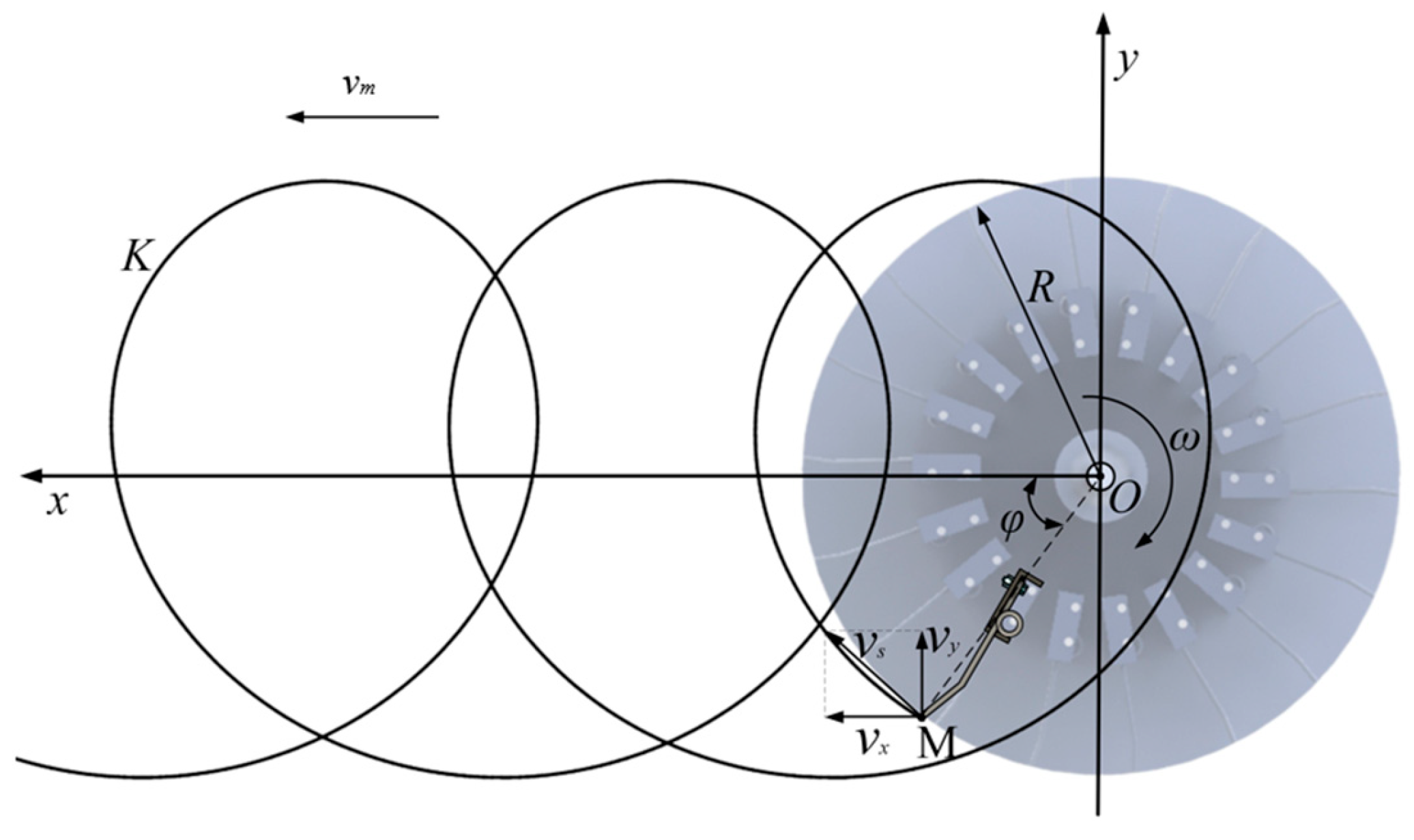
Given a fixed roller’s radius, the linear velocity of the spring tooth’s outer edge is determined by both the rotational radius and the rotational speed of the spring tooth. The spring tooth’s rotation exerts a centrifugal force on the pepper, which is proportional to the square of its angular velocity. If the rotational speed is too low, the peppers will remain attached to the plants; if too high, it may cause mechanical damage or uprooting of the plants. As the spring tooth rotates, it exhibits both linear motion relative to the ground and rotational motion about the roller axis, with each point on the spring tooth combining these motions. Figure 5 illustrates a planar Cartesian coordinate system with the x-axis aligned with the harvester’s forward movement and the y-axis vertically upwards, using the roller axis as the origin. The initial phase is aligned with the x-axis. The harvester progresses at a constant speed vm, and the spring tooth rotates at an angular velocity (ω). Over time (t), the spring tooth rotates by an angle (φ = ωt), defining the trajectory of point M on the spring tooth’s outer edge as K.
The equation of motion for the point M at the endpoint of the outer edge of the spring tooth, in the coordinate system in Figure 6, is as follows:
x = r cos φ + v m t = r cos ( ω t ) + v m t y = r sin φ = r sin ( ω t ) v x = d x d t = v m ω r sin ω t v y = d y d t = ω r cos ω t a x = ω 2 r cos ( ω t ) a y = ω 2 r sin ( ω t )
where x is the abscissa of the spring-tooth, mm; y is ordinate of the spring-tooth, mm; vm is the forward speed of the harvester, m·s−1; ω is angular velocity of the spring-tooth roller, rad/s; t is the time, s; vx is the sub-velocity of the working speed in the x-axis direction, m·s−1; vy is the sub-velocity of the working speed in the y-axis direction, m·s−1; ax is the sub-acceleration of the working speed in the x-axis direction, m·s−2; ay is the sub-acceleration of the working speed in the y-axis direction, m·s−2.
Then, the absolute velocity (vs) equation of the point M of the spring tooth is:
v s = v m 2 + 2 ω 2 r 2 2 v m ω r sin ( ω t ) = v m 1 + 2 ( ω r v m ) 2 2 ( ω r v m ) sin ( ω t )
The rotation speed of the roller n is calculated:
n = 30 ω π = 30 k v m π r
where n is the rotational speed of the spring tooth, r·min−1.
Let the ratio of ωr to vm be the coefficient k, i.e., k = ωr/vm. At this point, Equation (3) is expressed as:
v s = v m 1 + 2 k 2 2 k sin ( ω t )
According to the law of conservation of momentum, the product of the impact force on the pepper and its action time is equal to the change in the momentum of the pepper, that is:
F t = m v s
where F is the impact force, N; Δt is pepper subjected to the impact of the time, s; m is the mass of pepper, g; Δv is change in pepper velocity, m·s−1.
The impact force between spring tooth and pepper is as follows:
F = m v m 1 + 2 k 2 2 k sin ( ω t ) t
As can be seen from Equation (7), the impact force F acting on the pepper is a function of ω and vm, where the ω is related to the n. Therefore, it can be inferred that the main factors affecting the performance of the harvester are the roller’s rotational speed and the forward speed. In order to verify the theoretical analysis and improve the performance of the picking device, multi-factor tests were carried out on the picking device.
From the above analyses, it is evident that the motion of the spring tooth is a combination of the forward motion of the harvester and the rotational motion of the spring-tooth roller; the shape of the trajectory depends on the ratio coefficient k. The kinematic simulation and comparative analysis of the roller’s motion trajectory were conducted using ADAMS 2020 software. The simulated trajectory is a pendulum, as shown in Figure 7, and the shape of the pendulum depends on the value of the characteristic parameter k. There are three different values of k: k < 1, k = 1, and k > 1. To throw the pepper backward, the spring tooth must have a horizontal backward velocity when it reaches the highest point. The linear velocity at the tooth’s endpoint must be greater than the forward speed, i.e., k > 1. However, if k is too large, the impact of the tooth on the pepper will increase, resulting in greater losses.
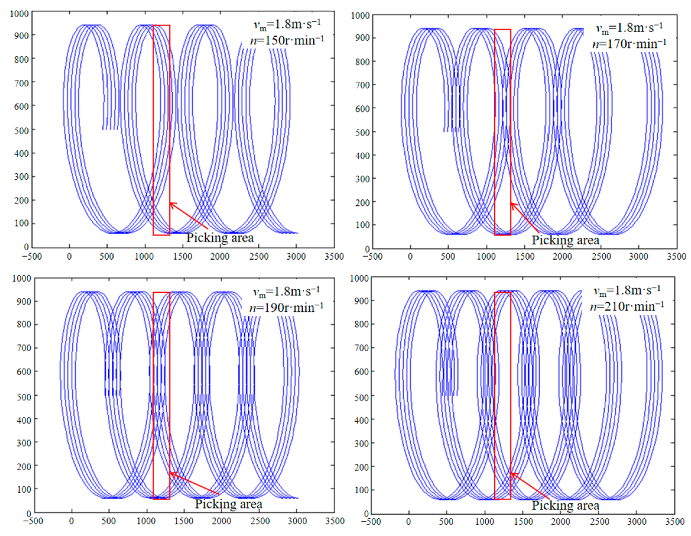
According to the above research, r = 425 mm, n = 120~240 r·min−1. The motion trajectory of the spring-tooth tip at different n was simulated and analyzed. The vm of the harvester was 1.8 m·s−1, and the n was divided into ranges of 20 r·min−1. Finally, 150 r·min−1, 170 r·min−1, 190 r·min−1, and 210 r·min−1 were determined as the characteristic values for analysis [36]. ADAMS 2020 software was used to simulate the trajectory curves of different roller’s rotational speeds by setting four different speeds at the same forward speed. The simulation results clearly show the trajectories of the spring teeth. By analyzing the cross density of adjacent curves in the trajectory region, the denser the cross density, the lower the probability of missed picking. Combining simulation analysis of trajectory and determination of agronomic parameters, we can preliminarily determine the optimal rotational speed. As seen in Figure 8, when vm = 1.8 m·s−1, the picking area is more reasonable at n = 170 r·min−1 and 190 r·min−1, the motion trajectory can cover the picking area. However, preliminary experiments have shown that at higher speeds, more pepper leaves are picked, and the impurity content increases [37]. Therefore, considering the same picking rate, the n can be preliminarily set at 170 r·min−1.

2.2.3. Structural Design of Spring Tooth

The roller has Ns rows of spring tooth uniformly distributed around its circumference. The spring teeth are bolted to the spring-tooth board, forming a single-point fixed cantilever beam structure as shown in Figure 9. As the roller rotates, the outer edge of the spring tooth is subjected to a force, which can be expressed as follows during normal operation:
F N = F f + m g cos π ϕ + f
where FN is the force normal to the spring tooth and pepper, N; Ff is the fruit-stalk bonding force, N; f is the friction between the spring tooth and the pepper plant, N; ϕ is the bending angle of the spring tooth, (°).
The maximum static stress (σ) applied to the outer edge end of the spring tooth can be expressed as:
M = L 3 · F N δ = L 3 3 · F N 3 E I I = π d s 4 64 W = π d s 3 32 σ = M W
where M is the bending moment of the spring tooth, N·mm; L3 is the moment arm from the outer edge to the base of the spring tooth, mm; δ is the deflection of the end point of the spring tooth, mm; E is the elastic modulus of the spring-tooth material, MPa; I is the moment of inertia of the spring-tooth section, mm4; ds is the diameter of the spring tooth, mm; W is the bending section coefficient, mm3.
The binding force range of the fruit stem is 8.6–16.4 N. To ensure structural stability, the spring tooth is made of a 65 Mn spring with a length L3 of 220 mm and a diameter of 7.5 mm. Additionally, a longitudinal fixing belt on the spring-tooth plate limits maximum deformation and reduces stress concentration at the base. The δ of the spring tooth is calculated to be 12.37 mm, and the maximum σ at the base of the spring tooth is 401 MPa.
The row spacing for pepper plants is set to 400 mm. To simultaneously harvest two rows, the initial spacing between two spring teeth is set at 65 mm in a linear arrangement. The spring plate consists of 18 spring teeth arranged in 9 groups, with each longitudinal row consisting of three adjacent helical spring teeth, forming a cycle every three groups.
Red cluster pepper tends to accumulate at the branch tips, and to ensure that every pepper is harvested, the spring tooth needs to be used several times on the same fruiting area. The duration (th) for the roller to traverse the plant’s fruiting area is given by:
t h = W f v m
where Wf is the width of the area, cm.
The rotation angle of the roller during this period (λ) is as follows:
λ = 2 π ω t h 60 = 2 π ω W f 60 v m
Let each cluster of peppers be picked clean after ns strikes of the elastic teeth, then the relationship between the total number of rows of spring-tooth Ns on the drum and where can be formulated as:
N s = 2 π n s λ = 60 n s v m ω W f
According to the pre-test, the Wf is set at 17 cm, and the vm at 1.5 m·s−1. According to the Adams simulation, n is at 170 r·min−1, and Ns can be formulated as
N s = 3 n s
Given the dense distribution of red cluster pepper, to ensure thorough cleaning, the ns is set at 6, with a total of 18 rows of spring tooth.

2.3. Design of the Conveying Device

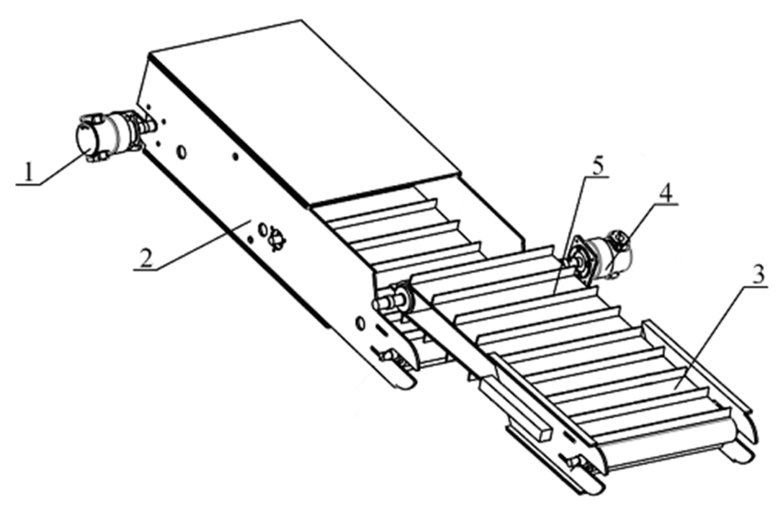
The conveying device is a crucial component of the harvester for lifting peppers, primarily comprising two parts: the first-level conveyor and the second-level conveyor. The second-level conveyor, situated above the first-level conveyor, transports peppers from the picking device to the collecting device, preventing congestion by ensuring timely transport. To effectively prevent the peppers from rolling off and to minimize collision damage during transport, both conveyors are equipped with rubber baffles of a specified height, spaced at regular intervals along the conveyor belt. The entire conveying device is powered by a hydraulic motor and driven by a conveyor belt. The structure is illustrated in Figure 10.
As the peppers move from the first-level to the second-level conveyor, their posture changes due to the initial speed (vt1) of the first-level conveyor belt. The motion and force analysis are illustrated in Figure 11. Points O1, O2, and O3 correspond to the center of mass at the first stage lift point a (vertical projection point), b (impact contact point), and c (transport stability point) of the conveyor belt, respectively. When the pepper moves onto the second-level conveyor belt, the height difference (hy) between the two belts causes the pepper to experience an impact force (FN1) and friction, which quickly stabilizes the pepper and keeps it relatively static with the conveyor belt. Large impacts can cause damage to the peppers or make them roll downward [38]. Therefore, the lifting angle and conveying speed are key parameters affecting the performance of the conveyor.
(1) At the moment of the pepper release (point a), the friction force (f1) and gravity (mg) are balanced, allowing a smooth transport by the first-level conveyor. Due to the conveying angle (β1) of the first-level conveyor belt, the pepper begins to fall after reaching the right end of the belt and is then thrown to the highest point, where velocity in the y-axis direction is zero. In fact, the vt1 satisfies the law of conservation of kinetic energy:
m g Δ h = 1 2 m ( v t 1 sin β 1 ) 2
where Δh is the vertical increase in the throwing height, m.
(2) At the impact moment (point b), the pepper falls at a certain speed and angle from the highest point onto the second-level conveyor belt:
1 2 m v a 2 = 1 2 m v t 1 2 + m g h y v a = v a x 2 + v a y 2 v a x = v t 1 cos β 1 v a y = v t 1 sin β 1 + g t tan θ 1 = v a y v a x
where va is the closing speed of the pepper after throwing, m·s−1; vax is the component of va in the x-axis direction, m·s−1; vay is the component of va in the y-axis direction, m·s−1; t1 is the movement time of the pepper from point O1 to O2, s; θ1 is the angle between vax and vay, (°).
Ignoring the generated contact shock pulsation, the condition for the pepper not to slide is that the dynamic friction force at the contact point must be greater than the downward force of the conveyor belt, that is:
f 2 = m g cos β 2 + F N 1 sin θ 1 + β 2 μ d m g sin β 2 F N 1 cos θ 1 + β 2
where f2 is the friction force on the pepper at point b, N; FN1 is the instantaneous impact force on the pepper, N; μd is the dynamic friction coefficient of the conveyor belt; β2 is the conveying angle of the second-level conveyor belt, (°).
Therefore, it can be obtained that:
F N 1 m g sin β 2 m g cos β 2 μ d cos θ 1 + β 2 + sin θ 1 + β 2 μ d
Considering the red cluster pepper fruit as a rigid body, materials such as nylon and rubber can be considered as linear elastomers in small deformations. In this case, the condition of impact collision loss does not occur:
σ d = F N 1 A σ τ
The relationship between load and deformation is as follows:
F N 1 = K d m g K d = 1 + 1 + v a 2 g Δ ε Δ d = K d Δ ε
where σd is the impact stress, MPa; A is the impact contact area, m2; [στ] is the critical stress for pepper damage, MPa; Kd is the dynamic loading factor. Δd is the maximum deformation of the crawler after an impact, m; Δε is the maximum deflection of the crawler from an equal static load, m.
(3) At the stable moment (point c), the contact impact force decreases to zero after a short transport distance. At this time, the pepper is transported at a constant speed due to the static friction force of the conveyor belt. Ignoring the influence of device vibrations, the condition for the pepper not to roll is that the static friction force must be greater than the resultant force of downward rolling:
f 3 = μ j m g cos β 2 m g sin β 2
where f3 is the friction force on the pepper at point c, N; μj is the static friction factor of the second-level conveyor belt.
The f3 of the second-level conveyor belt is 0.72, and the angle β2 ≤ 37°.
As mentioned above, the value range of β1 is 25°~40°, the value of β2 is not greater than 37°, and the value of vt1 is not less than 1.65 m·s−1. According to the actual operation requirements and installation position, β1 is set to 30°, β2 is set to 35°, vt1 = 1.85 m·s−1, and vt2 = 2.1 m·s−1.

2.4. Design of the Collecting Device

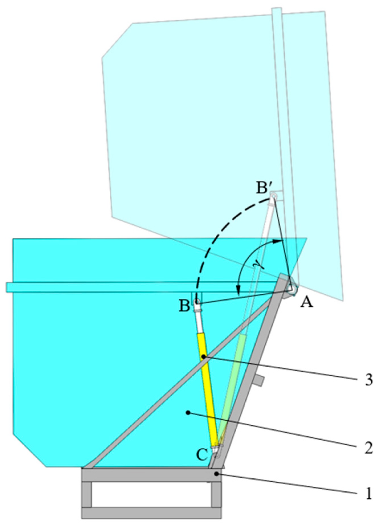
The harvester’s collecting device is primarily used to temporarily store the harvested peppers during the picking and conveying process, thereby increasing the harvester’s loading capacity. This system includes the aggregate box, frame, and hydraulic cylinder, as shown in Figure 12. The aggregate box is attached to both the support rod and the frame at point A via a pin connection, allowing the box to rotate around this axis. The base of the hydraulic cylinder is hinged to the frame at point C through a hinged block, while the piston rod’s apex is connected to the side of the aggregate box at point B. During the unloading process, hydraulic oil activates the cylinders on either side of the aggregate box, causing the piston rods to lift and rotate the box around point A, thereby facilitating the unloading. The aggregate box measures 1500 mm × 1380 mm × 1126 mm and can hold up to 400 kg of peppers per load. To ensure that the material can be fully unloaded when the aggregate box is turned over to the specified unloading position, γ should be γ ≥ π/2. The distance between hinge points A and C is 1120 mm, while the distance between points A and B is 500 mm.

2.5. Design of the Hydraulic System and Crawler Driven Device

2.5.1. Design of the Crawler-Driven Device

To ensure stable operation in hilly regions, the harvester uses a rubber crawler chassis. Comprising a drive frame, walking hydraulic motor, hydraulic pump, diesel engine, and crawler chassis, this chassis facilitates stable movement and component connection, as depicted in Figure 13. After field investigations, considering the harvester’s total weight, hilly regions, small row spacing, and overall structure, the wheelbase of the crawler chassis is set at 1300 mm, with the model chosen as CRT-350×90AP-48-050. The harvester is powered by a diesel engine with a rated power of 39 kW and a speed of 2400 r·min−1.

2.5.2. Design of the Hydraulic System

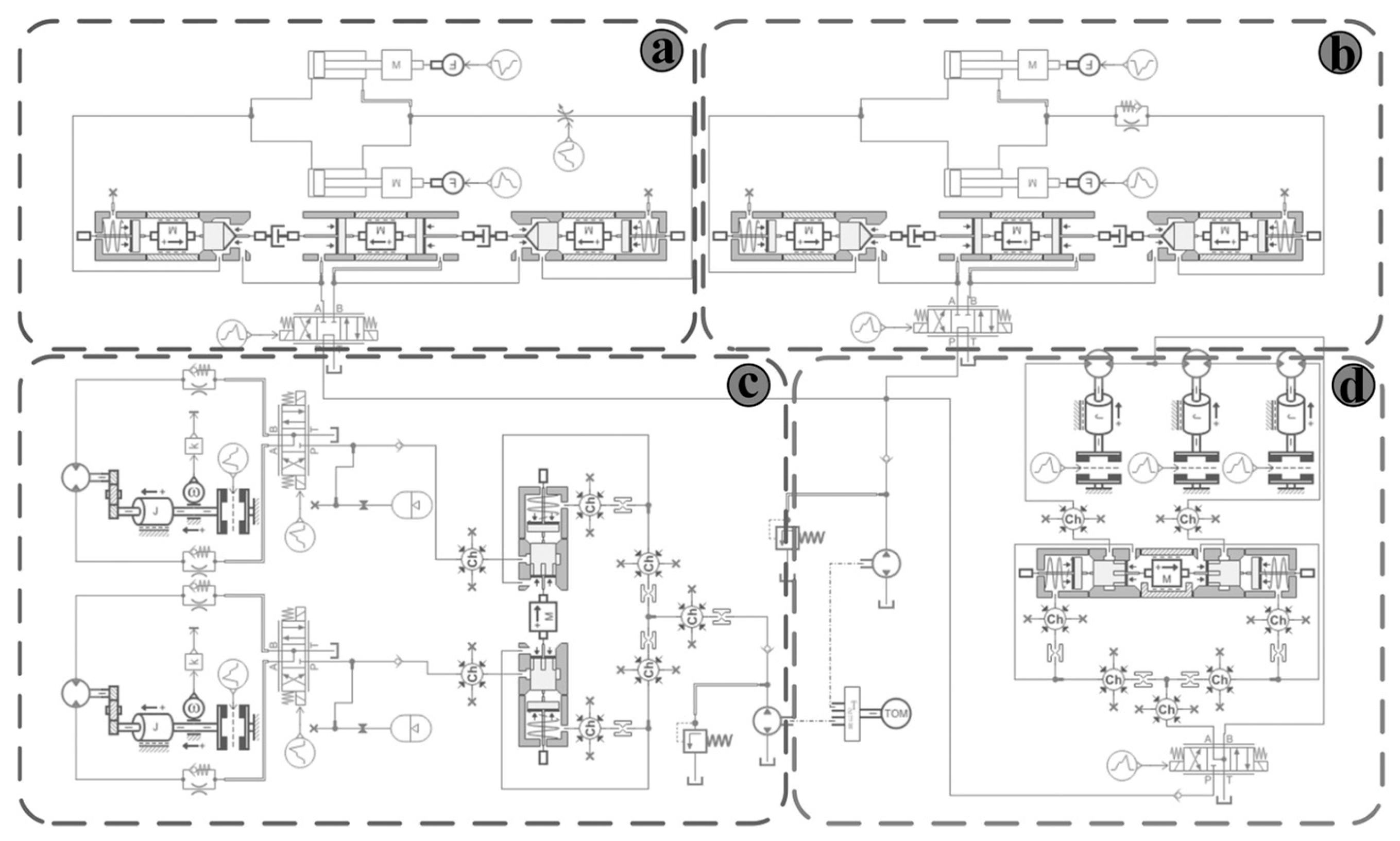
The drive system of the harvester is primarily hydraulic (Figure 14), which transmits power to each component of the harvester. The hydraulic system consists of three parts: (1) The high-speed hydraulic circuit, where the hydraulic motors of the first-level and second-level conveyor are connected in series, and this series circuit is connected in parallel with the hydraulic motor of the picking device. A synchronous valve at the input to the circuit ensures equal flow distribution to each hydraulic motor. Additionally, the speed of each motor can be adjusted via a control valve. (2) The hydraulic cylinder circuit, which includes two sets of hydraulic cylinders responsible for lifting the picking device, is connected in parallel and controlled by a manual valve. The hydraulic cylinder circuit for turning the aggregate box is similarly configured and connected in parallel with the former. (3) The crawler drive circuit is composed of two groups of walking hydraulic motors in parallel, with a synchronous valve at the circuit entrance to ensure equal flow to the left and right hydraulic motors. Due to the variability of field operations and the different physical characteristics of the pepper plants, the load on these hydraulic components dynamically changes during the harvester’s operation.
(1) The high-speed hydraulic circuit
For the picking device, the rotating shaft of the spring tooth roller is directly driven by a hydraulic motor. The total power (P1) required by the spring-tooth roller for brushing peppers per unit working stroke mainly includes brush power (P1s), idling power (P1k), and mechanical energy (P1j) transmitted to the pepper plant. Considering the work conducted by the rotating brush on the inertial force of the pepper, the power coefficient (λs) [39] is introduced. The power required for the hydraulic motor of the picking device per unit stroke is calculated as follows:
P 1 = P 1 s + P 1 k + P 1 j P 1 s = λ s p s S P 1 j = m g h g + m v 1 j 2 / 2
where S is the number of combed pepper plants in the unit stroke; hg is the lifting height of pepper fruit, m; v1j is the speed obtained after cutting the pepper fruit, m·s−1.
Based on the above design parameters, it can be calculated that P1s is 0.48 kW, the mechanical power transferred to the pepper plant is about 0.06 kW, and P1k is 0.78 kW based on the data.
The formulas for calculating the displacement (V1m) of the hydraulic motor and the maximum flow (Q1h) of the input hydraulic motor are as follows:
V 1 m = 2 π T 1 max ( p 1 p 1 b ) η 1 m Q 1 h = n 1 max V 1 m η 1 v
where p1 is the working pressure of the hydraulic motor, MPa; p1b is the back pressure of oil return, 0.6 MPa; η1m is the mechanical efficiency of the hydraulic motor, 0.90; η1v is the volumetric efficiency of the hydraulic motor, 0.92; n1max is the maximum rotational speed of the spring-tooth roller, r·min−1.
In this paper, the maximum rotational speed (n1max) of the roller design is 240 r·min−1, and the maximum load torque of the hydraulic motor (T1max) is 248 N·m, according to this selection of the BMR-160 hydraulic motor. For the two conveyors, the two drive shafts and hydraulic motors are directly connected; according to the conclusion of the study above, the power of the two is less than the power of the picking device. Therefore, according to the hydraulic motor selection and design method of picking the device, the BMR-125 hydraulic motor is uniformly adopted, which meets the working requirements after calibration.
(2) The hydraulic cylinder circuit: for the lifting hydraulic cylinder circuit of the picking device, the weight of the picking device is 350 kg. Calculation parameters related to hydraulic cylinders are as follows:
F L = m p g 2 cos θ L D c = 4 F L π η 2 [ p 2 p 2 b ( 1 φ h 2 ) ] q out = π D c 2 v L 4
where FL is the hydraulic cylinder thrust, N; mp is the weight of the picking head, kg; θL is the angle between the hydraulic cylinder and the horizontal direction when pushed to the maximum, 25°; Dc is the inner diameter of the hydraulic cylinder, mm; η2 is the hydraulic cylinder efficiency, 0.96; p2 is the oil inlet pressure, 12 MPa; p2b is the back pressure of the loop, 0.1 MPa; φh is the rod diameter ratio, 0.56; qout is the flow rate required when the hydraulic cylinder is extended, L/min; vL is the cylinder rod extension speed, 0.05 m·s−1.
The lifting hydraulic cylinder of the picking device is finally selected as HSG50-400.
The structure and working principle of the aggregate box turning hydraulic cylinder are essentially the same as those of the lifting hydraulic cylinder of the picking device. Therefore, according to the selection and design method of the picking device’s lifting hydraulic cylinder, the HSG63-800 hydraulic cylinder is uniformly used, meeting the working requirements after verification.
(3) The 4TE45 diesel engine is selected as the power source for the crawler drive system, considering its adaptability, cost-efficiency, and high output torque, which are essential for the operation of the harvester. This engine has a rated power of 39 kW and a rated speed of 2400 r·min−1.
The relevant calculation parameters for the crawler hydraulic motor are as follows:
F t max = sin α max + f g cos α max G M m max = 0.6 F t max r d η k η M V 2 m = 1.2 π F t max r d Δ p η M η k
where Ftmax is the maximum tangential gravity of the harvester, N; αmax is the maximum climbing angle of the harvester, (°); fg is the rolling resistance coefficient, 0.1; G is the full load weight of the car, kg; rd is the radius of the drive wheel, mm; ηk is the crawler drive end efficiency, 0.95; ηM is the reducer transmission efficiency, 0.95; V2m is crawler hydraulic motor displacement, mL/r.
To match the engine, data were consulted, and the crawler hydraulic motor with a torque of 412 N·m, model HQX2-305, was selected.

2.6. The Field Test Design

The field test was conducted in Suiyang County, Zunyi City, Guizhou Province, in a high-yield area of red cluster pepper. The test field measured 60 m in length and 20 m in width, with a planting ridge surface width of 600 mm, suitable for harvester operation. On the day of the test, the temperature was 30 °C, the average water content of peppers was 53.48%, the average plant height ranged from 450 to 700 mm, the average number of effective branches was 9.5, and the average number of fruits per pepper was 55. The main test equipment included a pepper harvester, a 50 m measuring tape, a camera, a vernier caliper (accuracy 0.02 mm), and a stopwatch.

2.6.1. Test Factors and Indexes

This test mainly investigates the harvesting performance of the harvester’s picking device. The test indexes are the impurity rate (Y1), damage rate (Y2), loss rate (Y3), and hanging rate (Y4) of red cluster pepper were taken as test indexes. Each index is expressed as follows:
Y 1 = M I M T × 100 % Y 2 = M B M T × 100 % Y 3 = M D M T × 100 % Y 4 = M L M T × 100 %
where MT is the total mass of all the peppers in each test, kg; MD is the total mass of peppers falling to the ground in each test, kg; ML is the total mass of peppers still connected to a pepper stick after each test, kg. MI is the mass of impurities in the peppers harvested in each test, kg; MB is the total mass of damaged peppers after each test, kg.

2.6.2. Test Methods

In this test, the two-factor, five-level quadratic orthogonal experiment was used to fit the functional relationship between the test factor and the target value by using the binary quadratic equation. By establishing the regression equation, the functional relationship was analyzed to determine the influencing factors of the target value and to search for the optimal combination of parameters.
Based on the above analysis of the motion trajectory of the spring-tooth roller, factors with relatively good comprehensive indexes were evaluated. The forward speed vm of the harvester is about 1.5 m·s−1, and the speed n is about 170 r·min−1. In this study, these values are used as the reference points for the multi-factor combination test, with adjacent levels varying by 0.25 m·s−1 and 20 r·min−1, respectively. Each group of experiments was repeated three times, and the levels of the test factors are listed in Table 2.

3. Results

3.1. Analysis of Response Surface Experiments Results

The orthogonal test results are shown in Table 3.
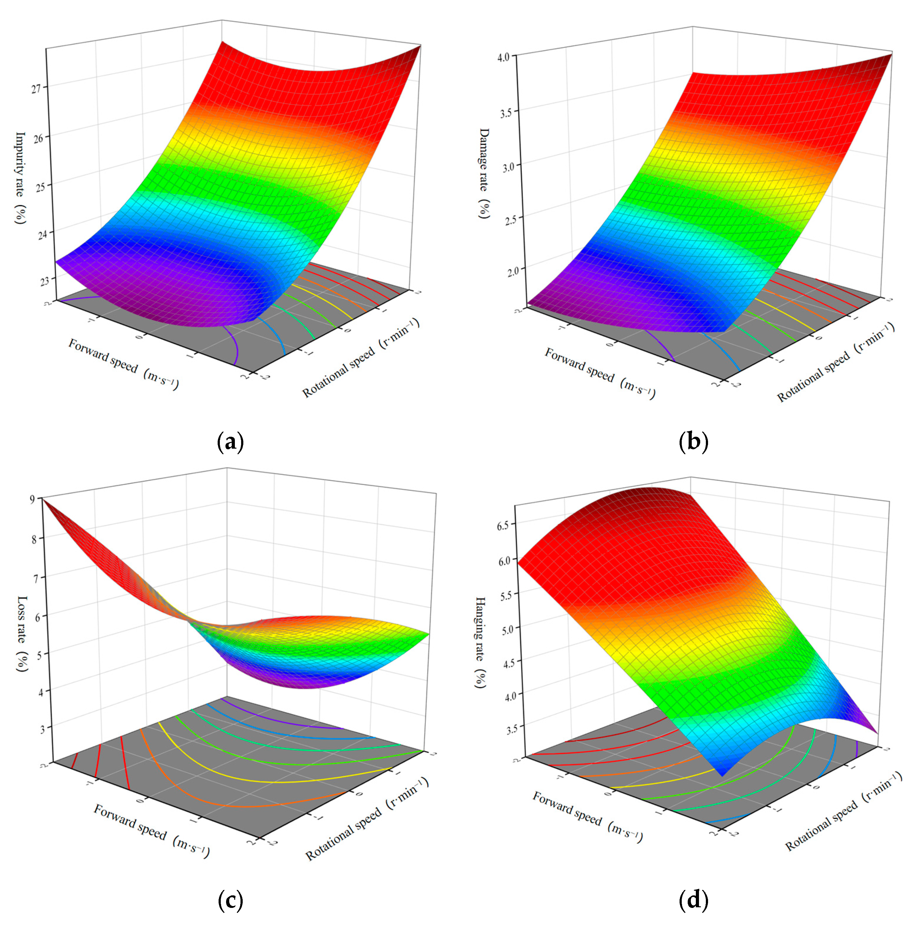
The regression analysis of the test results was conducted using Design Expert 13 software, yielding the regression equations between the four test target values (Y1, Y2, Y3, and Y4) and various factors. The variance analysis of the evaluation indicators is shown in Table 4. Through further processing by the software, the influence of the interaction of each test factor on the target value can be determined, allowing for a more intuitive expression of the relationship between the test factors and the evaluation indexes.
(1)
Impurity rate
It can be seen from Table 4 that the whole model with Y1 is significant (p < 0.001). The linear and quadratic effects of each parameter and their interaction on the Y1 are as follows: X2, X22, X1, X12, X1X2, among which X2 has a strong significant influence (p < 0.001), X22 has significant influence (p < 0.001), and other factors are not significant. After removing the non-significant factors, the regression equation with impurity content is as follows:
Y 1 = 24.06 + 0.15 X 1 + 2.04 X 2 0.08 X 1 X 2 + 0.60 X 1 2 + 0.79 X 2 2
As shown in Figure 15a, when the forward speed of the harvester is unchanged, the Y1 increases with an increase in the roller’s rotational speed, and the change is large.
(2)
Damage rate
Table 4 shows that Y2 is significant throughout the model (p < 0.001). The linear and quadratic effects of each parameter and their interaction on the Y2 are as follows: X2, X1, X22, X12, X1X2, in which X2 has a highly significant effect (p < 0.001), X1 has significant influence (p < 0.01), X22 has significant influence (p < 0.01), while other factors are not significant. After removing the non-significant factors, the regression equation of the Y2 is as follows:
Y 2 = 2.42 + 0.10 X 1 + 0.478 X 2 + 0.005 X 1 X 2 + 0.023 X 1 2 + 0.068 X 2 2
As shown in Figure 15b, if the forward speed of the harvester is unchanged, the Y2 increases with an increase in the roller’s rotational speed, and the change range is large. If the rotational speed is unchanged, the Y2 increases slowly with an increase in the forward speed, and the change is not large.
(3)
Loss rate
It can be seen from Table 4 that the whole model of the Y3 is significant (p < 0.001). The linear and quadratic effects of each parameter and their interaction have the following major and secondary effects on the Y3: X2, X12, X1X2, X22, X1, where X2 has a high significant effect (p < 0.001), X12 has a high significant effect (p < 0.01), while the other factors are not significant. After removing the insignificant factors, the regression equation of the loss rate is as follows:
Y 3 = 5.22 0.045 X 1 0.968 X 2 0.255 X 1 X 2 + 0.288 X 1 2 0.064 X 2 2
As shown in Figure 15c, when the forward speed of the harvester is unchanged, the Y3 increases with a decrease in the roller’s rotational speed, and the change range is large.
(4)
Hanging rate
The whole model of Y4 is significant (p < 0.001) in Table 4. The linear and quadratic effects of each parameter and their interaction on the Y4 are as follows: X2, X1, X22, X1X2, X12, where X2, X1, and X22 have highly significant effects (p < 0.001), and X1X2 has a significant effect (p < 0.05). Other factors are not significant. After removing the non-significant factors, the regression equation of Y4 is as follows:
Y 4 = 5.37 0.171 X 1 0.511 X 2 0.065 X 1 X 2 0.014 X 1 2 0.122 X 2 2
As shown in Figure 15d, when the forward speed of the harvester is unchanged, the Y4 shows an increasing and then decreasing trend with an increase in rotational speed. When the rotational speed is constant, the Y4 increases with the increase in forward speed, and the change range is obvious.
Therefore, the comprehensive analysis shows that compared with the change in the forward speed, the change in the rotational speed has a greater effect on the evaluation index, and the rotational speed is the main factor affecting the working performance of the pepper harvester.

3.2. Parameter Optimization

A mature pepper harvester should have a low impurity rate, damage rate, loss rate, and hanging rate. Each parameter has a different effect on the objective values; therefore, a global multi-objective optimization is required to obtain the optimal working parameters. In this study, the forward speed and rotational speed were optimized using the pepper impurity rate, damage rate, loss rate, and hanging rate as the objective functions, and the mathematical model between the objective function and the constraint function is obtained as follows:
min y 1 min y 2 min y 3 min y 4 s . t . 1.0 x 1 2.0 130 x 2 210 0 y 1 x 1 , x 2 1 0 y 2 x 1 , x 2 1 0 y 3 x 1 , x 2 1 0 y 4 x 1 , x 2 1

3.3. Test Verification

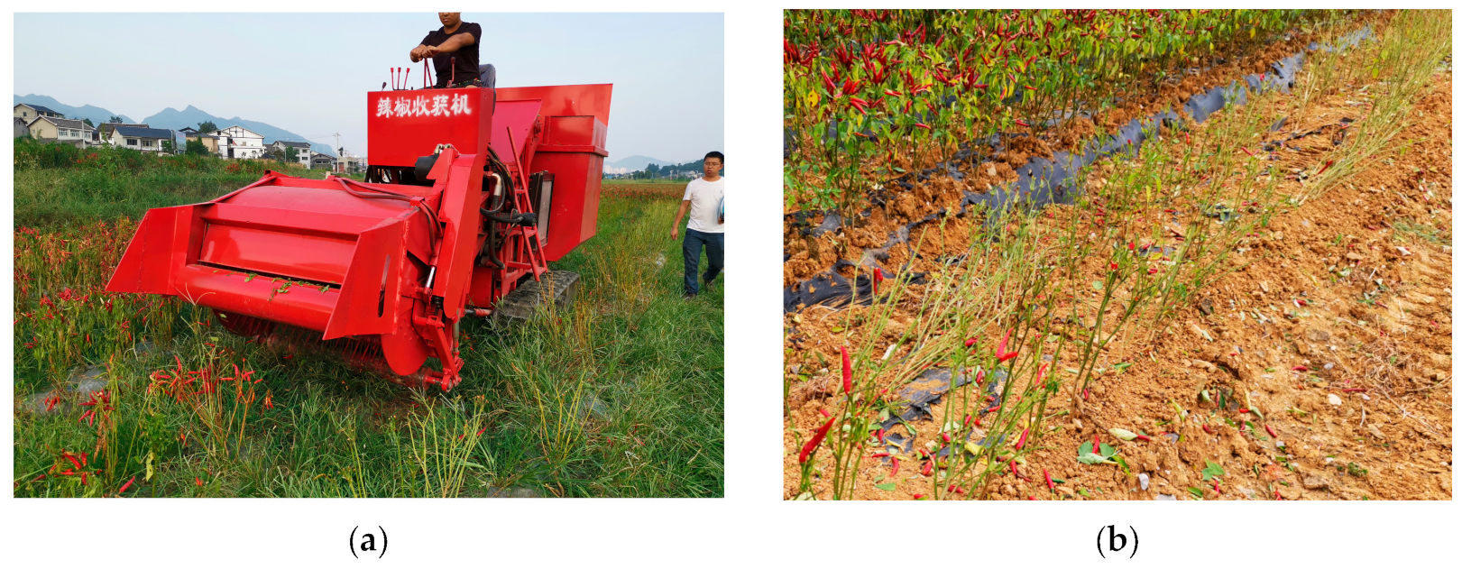
The evaluation index parameters were calculated using Design Expert 13 software. When vm = 1.75 m·s−1 and n = 181 r·min−1, the pepper harvester has the optimal operating performance; the impurity rate is 25.6%, the damage rate is 2.8%, the loss rate is 4.7%, and the hanging rate is 4.8%. Based on optimization results, the verification test is carried out according to the Determination of Experimental Conditions for Agricultural Machinery (GB/T5262-2008). The verification test was conducted at the Huanghuagang base in Zunyi City, Guizhou Province, China. The test area is spanned 100 m × 20 m. The verification test is illustrated in Figure 16. The performance test results of the pepper harvester are detailed in Table 5. The verification test results, as presented in Table 5, indicate that at vm = 1.75 m·s−1 and n = 181 r·min−1, the pure hourly productivity is 0.21 ha·h−1, the impurity rate is 26.7%, the damage rate is 2.3%, the loss rate is 6.1%, and the hanging rate is 4.2%, of which the loss rate and damage rate are lower than the industry standard. The test indicators meet the technical requirements, achieving the expected purpose.

4. Discussion

4.1. Discussion of Field Test Result

The harvester designed in this study made significant progress in achieving the harvesting function of peppers, and the overall performance was largely in line with the initial design requirements, being able to perform the tasks of picking, conveying, and collecting effectively. However, a number of problems were identified during the testing process, and these were analyzed to provide important references for future improvements.
(1)
During the harvesting process of peppers, there is a certain relative error between the optimized experimental results and the actual loss rate of peppers in the harvesting experiment. In practice, the harvesting of peppers is influenced by various factors, including plant growth, fruit shape, harvester operation, and weather conditions.
(2)
It was found in the field test that the different water content of pepper has a greater impact on loss and damage rates during harvesting. In addition, because the operation relies on manual labor, the difficulty is high, and the driver may make operational errors in the fatigue state, resulting in the forward speed of the harvester being difficult to achieve the desired effect. In this way, bench tests can be used to improve the operation performance and reduce the influence of human factors.
(3)
Field tests have found that the faster the forward speed, the higher the loss rate. This is because when the forward speed is too fast, the roller in this situation pushes the pepper plants. The chili plants were not fully harvested, and the harvester continued to move forward, resulting in missed harvesting.

4.2. Limitations and Prospects

In response to the shortcomings demonstrated by the harvester during the experimental process, follow-up work can be carried out in the following areas.
Due to the complex working conditions in the field, the spring tooth of the harvester not only comes into contact with the pepper fruit during the forward movement but also with the pepper and weeds on the stem and each leaf. During the work process, crushed stones and hard soil debris may be lifted, generating random impact loads that can cause deformation or fracture of the spring tooth, affecting the harvesting effect. At the same time, during the operation of the harvester, a series of situations such as vibration, tilting, and bumps caused by uneven ground result in changes in the height of the harvesting device, increasing the loss rate and hanging rate. In particular, variations in the density of the pepper fruit can lead to fluctuations in the roller load, impacting both the efficiency of the harvest and the potential for fruit damage [19].
In future research, intelligent control systems, optimization of spring teeth, path planning, and development of an adaptive control system for a roller’s rotational speed will be studied to achieve intelligent harvesting of pepper.

5. Conclusions

This study designed and developed a crawler-type red cluster pepper harvester suitable for hilly and mountainous regions. It achieved mechanized picking, conveying, and collecting operations of artichokes by defining the harvester’s overall structure and the main technical parameters and adopting an all-hydraulic drive power mode. The harvester includes a picking device, a conveying device, a collecting device, and a crawler chassis, effectively addressing the high labor intensity and low-efficiency issues associated with traditional manual picking.
(1)
Based on the planting pattern of red cluster pepper and its physical characteristics, an optimized spring-tooth roller-picking device was designed. The kinematic mechanism of the spring tooth in the picking process was analyzed and simulated, resulting in the determination of an optimal rotational speed range for the spring tooth roller, specifically between 150 r·min−1 and 210 r·min−1. Furthermore, force analysis and optimization of the spring-tooth structure were conducted to ensure stability and efficiency during picking.
(2)
A two-stage conveying system is developed. Motion stages and parameter conditions during conveying are analyzed to prevent impact damage and rolling of peppers. The design and selection of the collecting device and hydraulic transmission system ensure the overall harvester’s reliability and stability.
(3)
A crawler-type red cluster pepper harvester suitable for hilly mountain regions was finally developed. Key parameters—forward speed and rotational speed of the spring-tooth roller—were optimized through a two-factor, five-level test. A regression model correlating evaluation indexes with these factors was established using Design Expert 13 software, followed by field validation tests. Results indicated that the harvester achieved a productivity of 0.21 ha·h−1 at a forward speed of 1.75 m·s−1 and rotational speed of 181 r·min−1. Average impurity, loss, damage, and hanging rates were 26.7%, 6.1%, 2.3%, and 4.2%, respectively, demonstrating efficient performance in practical applications.

Author Contributions

Conceptualization, J.Y. and J.L.; methodology, J.Y. and J.L.; software, J.Y.; validation, J.Y. and J.L.; formal analysis, J.Y.; investigation, J.Y., Z.W. and J.L.; resources, J.Y. and X.Q.; data curation, J.Y. and L.L.; writing—original draft preparation, J.Y. and J.L.; writing—review and editing, J.Y., J.L. and X.Q.; visualization, J.Y. and J.L.; supervision, J.Y., J.L. and J.Z. All authors have read and agreed to the published version of the manuscript.

Funding

This study was supported by the National Natural Science Foundation of China (grant no. 62163032), the Financial Science and Technology Program of the XPCC (grant nos. 2024AB043, 2022CB011), and the Project of Achievement Transformation and Technology Extension of Shihezi University (grant no. CGZH202306).

Institutional Review Board Statement

Not applicable.

Data Availability Statement

The original contributions presented in this study are included in the article; further inquiries can be directed to the corresponding author.

Conflicts of Interest

The authors declare no conflicts of interest.

References

  1. Wang, L.H.; Ma, Y.Q.; Zhang, B.X. Market Demand and Breeding Trend of Pepper Varieties in China. China Veg. 2019, 8, 1–4. [Google Scholar] [CrossRef]
  2. Wang, J.; Du, D.D.; Hu, J.B.; Zhu, J.X. Vegetable Mechanized Harvesting Technology and Its Development. J. Chin. Agric. Mech. 2024, 45, 81–87. [Google Scholar] [CrossRef]
  3. Zou, X.X.; Ma, Y.Q.; Dai, X.Z.; Li, X.F.; Yang, S. Spread and Industry Development of Pepper in China. Acta. Hortic. Sin. 2020, 47, 1715–1726. [Google Scholar] [CrossRef]
  4. Qiao, L.J.; Zhao, B.H.; Zong, Y.X.; Kou, C.Y.; Dong, Y.H. Development Current Situation, Tendency and Countermeasure for China’s Pepper Industry. China Veg. 2023, 1–7. [Google Scholar] [CrossRef]
  5. Mou, Y.M.; Mao, F.F.; Zhang, S.G. Current Situation and Development Suggestions of Pepper Industry in Guizhou Province. China Veg. 2020, 2, 10–12. [Google Scholar] [CrossRef]
  6. Yu, W.; Yan, X.; Yang, H.; He, L. Problems and Development Countermeasures of Mechanized Production of Pepper in Guizhou. Shanghai Veg. 2022, 4, 87–88. [Google Scholar]
  7. Chen, J. A New Countermeasure against Two Severe Difficulties in Agricultural Mechanization in China’s Hilly and Mountainous Areas. J. Agric. Mech. Res. 2019, 41, 64–67. [Google Scholar] [CrossRef]
  8. Hu, S.J.; Chen, Y.C.; Yuan, Y.X.; Han, L.L. Research Status and Prospects of Pepper Harvesters. J. Agric. Mech. Res. 2011, 33, 237–240. [Google Scholar] [CrossRef]
  9. Liu, X.F.; Chen, Y.C.; Qin, X.Y.; Zhao, J. The Development of Chili Pepper Harvester of the Type of 4LS-1.6. J. Agric. Mech. Res. 2012, 34, 135–138. [Google Scholar] [CrossRef]
  10. Qin, X.Y.; Chen, Y.C.; Zhang, F.Q.; Liu, X.F.; Hu, S.J.; Xiong, Z.Y.; Yuan, Y.X. Design and Research of Chili Pepper Harvester of the Type of 4LZ-3.0. J. Agric. Mech. Res. 2012, 34, 53–56. [Google Scholar] [CrossRef]
  11. Lei, M.J.; Kong, L.J.; Chen, Y.C.; Zhou, H.Y.; Duan, Y.L.; Tian, K. Research and Design of Spring-Tooth Drum Type Pepper Picking Device. J. Chin. Agric. Mech. 2014, 35, 161–165. [Google Scholar]
  12. Kong, L.J.; Chen, Y.C. Design and Mechanism Analysis of 4LZ-3.0 Pepper Harvester. J. Chin. Agric. Mech. 2015, 36, 16–19. [Google Scholar] [CrossRef]
  13. Duan, Y.; Kong, L.; Chen, Y.; Lei, M.; Tian, K. Tine Drum Pepper Picking Device Picking Hot Pepper Mechanical Damage Characteristics and Mechanism. J. Chin. Agric. Mech. 2014, 35, 79–82. [Google Scholar]
  14. Wang, G.; He, B.; Han, D.; Zhang, H.; Wang, X.; Chen, Y.; Chen, X.; Zhao, R.; Li, G. Investigation of Collision Damage Mechanisms and Reduction Methods for Pod Pepper. Agriculture 2024, 14, 117. [Google Scholar] [CrossRef]
  15. Du, C.; Han, D.; Song, Z.; Chen, Y.; Chen, X.; Wang, X. Calibration of Contact Parameters for Complex Shaped Fruits Based on Discrete Element Method: The Case of Pod Pepper (Capsicum annuum). Biosyst. Eng. 2023, 226, 43–54. [Google Scholar] [CrossRef]
  16. Deng, L.; Liu, T.; Jiang, P.; Qi, A.; He, Y.; Li, Y.; Yang, M.; Deng, X. Design and Testing of Bionic-Feature-Based 3D-Printed Flexible End-Effectors for Picking Horn Peppers. Agronomy 2023, 13, 2231. [Google Scholar] [CrossRef]
  17. Gupta, C.; Tewari, V.K.; Machavaram, R. Evaluation of a Laboratory-Based Prototype of a Comb-Type Picking Mechanism for Chili Pepper Harvester. J. Biosyst. Eng. 2022, 47, 69–78. [Google Scholar] [CrossRef]
  18. Paul, A.; Machavaram, R.; Ambuj; Kumar, D.; Nagar, H. Smart Solutions for Capsicum Harvesting: Unleashing the Power of YOLO for Detection, Segmentation, Growth Stage Classification, Counting, and Real-Time Mobile Identification. Comput. Electron. Agric. 2024, 219, 108832. [Google Scholar] [CrossRef]
  19. Zhang, X.; Qin, X.; Lei, J.; Zhai, Z.; Zhang, J.; Wang, Z. A Novel Method on Recognizing Drum Load of Elastic Tooth Drum Pepper Harvester Based on CEEMDAN-KPCA-SVM. Agriculture 2024, 14, 1114. [Google Scholar] [CrossRef]
  20. Yuan, X.W.; Yang, S.P.; Jin, R.C.; Zhao, L.Y.; Zheng, N.; Fu, W.P. Design and Experiment of Double Helix Pair Roller Pepper Harvesting Device. Trans. Chin. Soc. Agric. Eng. 2021, 39, 1–9. [Google Scholar]
  21. Zhang, Q.F.; Zhong, B.; Sun, S.G.; Qin, X.T.; Liu, X.F.; Liu, X.C. Design of HXJ-1 Jujube Tree Pruning Machine. J. Agric. Mech. Res. 2020, 42, 128–132. [Google Scholar] [CrossRef]
  22. Han, D.; Zhang, H.; Li, G.; Wang, G.; Wang, X.; Chen, Y.; Chen, X.; Wen, X.; Yang, Q.; Zhao, R. Development of a Bionic Picking Device for High Harvest and Low Loss Rate Pod Pepper Harvesting and Related Working Parameter Optimization Details. Agriculture 2024, 14, 859. [Google Scholar] [CrossRef]
  23. Ji, X.; Tang, Y.; Lin, S.Y.; Zhang, D.J.; Zhang, T.H.; Xu, W.P. Dynamic Simulation and Test of the Tracked Chassis of the Mountainous Self-Propelled Pepper Harvester. J. Chin. Agric. Mech. 2022, 43, 72–80. [Google Scholar] [CrossRef]
  24. Wang, X.; Cao, Y.; Fang, W.; Sheng, H. Vibration Test and Analysis of Crawler Pepper Harvester under Multiple Working Conditions. Sustainability 2023, 15, 8112. [Google Scholar] [CrossRef]
  25. Zhang, D.J.; Lin, S.Y.; Ji, X.; Wu, D.; Zhang, T.H.; Xu, W.P. Stress Analysis and Simulation of the Mountain Pepper Harvester’s Track. J. Mach. Des. 2022, 38, 83–90. [Google Scholar] [CrossRef]
  26. Zhang, J.L.; Tang, Y.; Wu, D.; Lin, S.Y.; Zhang, T.H.; Xu, W.P. Design and Simulation of Mountain Pepper Harvester’s Hydraulic System. J. Mach. Des. 2024, 41, 94–101. [Google Scholar] [CrossRef]
  27. Li, H.; He, T.; Liu, H.; Shi, S.; Zhou, J.L.; Liu, X.C.; Wang, B.Q. Development of the Profiling Up-Film Transplanter for Sweet Potato in Hilly and Mountainous Region. Trans. Chin. Soc. Agric. Eng. 2023, 39, 26–35. [Google Scholar]
  28. Qu, Y.; Fang, Z.; Liu, Y.; Dai, Z.; Wu, M. Development of a Vibrating and Roller Pushing Type Allium Chinense Harvester. Trans. Chin. Soc. Agric. Eng. 2022, 38, 51–59. [Google Scholar]
  29. Geng, D.; Sun, Y.; Li, H.; Mou, X.; Zhang, G.; Wang, Z.; Lu, X. Design and Experiment of Crawler Corn Harvester for Sloping Fields. Trans. Chin. Soc. Agric. Eng. 2021, 37, 11–19. [Google Scholar]
  30. Shi, R.; Dai, F.; Liu, X.; Zhao, W.; Zhai, J.; Zhang, F.; Qin, D. Design and Experiments of Crawler-Type Hilly and Mountaineous Flax Combine Harvester. Trans. Chin. Soc. Agric. Eng. 2021, 37, 59–67. [Google Scholar]
  31. Li, Y.; Zhang, G.; Zhang, Z.; Zhang, Y.; Hu, T.; Cao, Q. Development of Low Power-Consumption Multi-Helical Rotavator for Small Vertical-Shaft Deep-Cultivator. Trans. Chin. Soc. Agric. Eng. 2019, 35, 72–80. [Google Scholar]
  32. Gao, Q.; Luo, Y.; Xiang, H.; Mi, Z.; Lv, P.; Cai, Y. Design and Test of Modular Sugarcane Cutting and Paving Machine in Hilly and Mountainous Area. Trans. Chin. Soc. Agric. Mach. 2023, 54, 71–80. [Google Scholar]
  33. Wang, F.A.; Cao, Q.Z.; Li, Y.B.; Pang, Y.L.; Xie, K.T.; Zhang, Z.G. Design and Trafficability Experiment of Self-Propelled Potato Harvester in Hilly and Mountainous Areas. Trans. Chin. Soc. Agric. Mach. 2023, 54, 10–19. [Google Scholar]
  34. Wang, C.; Shao, Y.; Zhang, Y.; Xin, Z.; Chen, J.; Zhang, W.; Yang, F. Design and Experimental Research of a Comb-Type Buckwheat-Harvesting Device. Agriculture 2023, 13, 1383. [Google Scholar] [CrossRef]
  35. Ren, C.; Tian, H.; Liao, W.; Zhou, A.; Zheng, Y. A New Pod Pepper F1 Hybrid—‘Chaotianjiao No.8’. China Veg. 2022; 107–109. [Google Scholar] [CrossRef]
  36. Du, C.; Fang, W.; Han, D.; Chen, X.; Wang, X. Design and Experimental Study of a Biomimetic Pod-Pepper-Picking Drum Based on Multi-Finger Collaboration. Agriculture 2024, 14, 314. [Google Scholar] [CrossRef]
  37. Chen, Y.; Zhao, Y. Key Technology and Equipment of Mechanized Pepper Harvest; China Agricultural Science and Technology Press: Beijing, China, 2018. [Google Scholar]
  38. Zhang, J.; Wang, J.; Du, D.; Long, S.; Wang, Y.; You, X. Design and Experiment of Crawler Self-Propelled Single-Row Harvester for Chinese Cabbage. Trans. Chin. Soc. Agric. Mach. 2022, 53, 134–146. [Google Scholar]
  39. Lei, J.; Qin, X.Y.; Chen, Y. Design and Analysis on Key Components of a Novel Chili Pepper Harvester’s Picking Device. Open Mech. Eng. J. 2015, 9, 540–545. [Google Scholar]
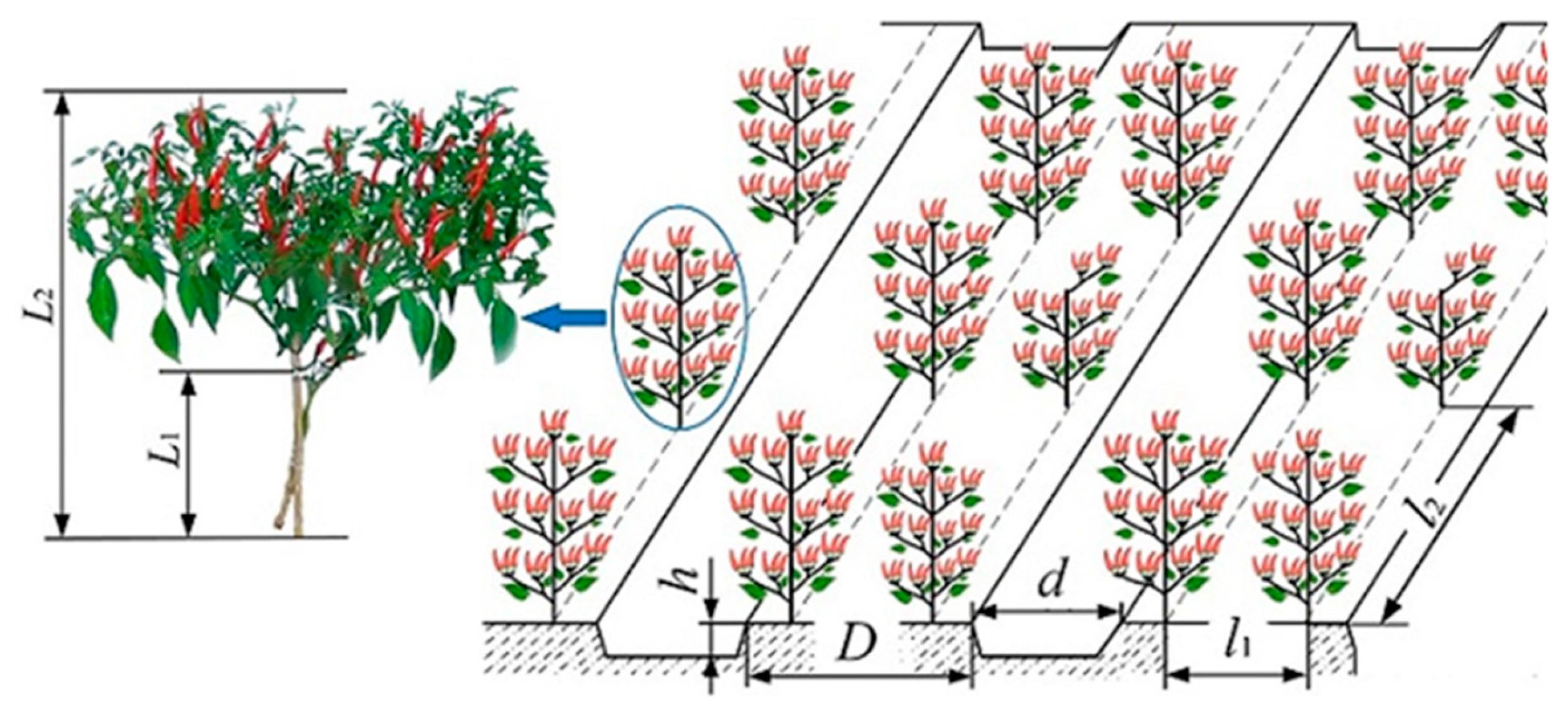
Figure 1. Planting pattern of red cluster pepper.
Agriculture 14 01742 g001
Figure 2. Schematic diagram of a crawler-type red cluster pepper harvester: 1. Picking device; 2. First-level conveyor; 3. Second-level conveyor; 4. Crawler chassis; 5. Collecting device; 6. Engine.
Agriculture 14 01742 g002
Figure 3. Structure diagram of picking device: 1. Spring-tooth roller; 2. Hydraulic motor of the roller; 3. Ground wheel; 4. Hydraulic lifting cylinder; 5. Cover plate; 6. Pressing roller.
Agriculture 14 01742 g003
Figure 4. Schematic diagram of the spring-tooth roller picking principle: 1. First-level conveyor; 2. Spring-tooth roller; 3. Pressing roller; 4. Pepper plant.
Agriculture 14 01742 g004
Figure 5. Schematic diagram of the structure of the spring-tooth roller: 1. Spring-tooth board; 2. Spring-tooth; 3. Bearing; 4. Roller shaft; 5. Side plate.
Agriculture 14 01742 g005
Figure 6. Motion analysis of the spring tooth.
Agriculture 14 01742 g006
Figure 7. Spring-tooth cycloid trajectory with different k values.
Agriculture 14 01742 g007
Figure 8. Trajectory of the outer edge of the spring-tooth at different speeds.
Agriculture 14 01742 g008
Figure 9. Force analysis of the spring tooth.
Agriculture 14 01742 g009
Figure 10. Schematic diagram of the conveying device: 1. Second stage hydraulic motor; 2. Second-level conveyor; 3. First-level conveyor; 4. First stage hydraulic motor; 5. Conveyor belt baffle.
Agriculture 14 01742 g010
Figure 11. Analysis of motion and forces during lift and transport. 1. First-level conveyor; 2. Second-level conveyor.
Agriculture 14 01742 g011
Figure 12. Schematic diagram of collecting device overturning: 1. Frame; 2. Aggregate box; 3 Hydraulic cylinders.
Agriculture 14 01742 g012
Figure 13. Schematic of the crawler-driven chassis: 1. Walking hydraulic motor; 2. Hydraulic pump; 3. Drive frame; 4. Crawler chassis; 5. Diesel engine.
Agriculture 14 01742 g013
Figure 14. Schematic diagram of hydraulic system. (a) Picking device hydraulic cylinder circuit, (b) Collecting device hydraulic cylinder circuit, (c) Crawler-driven system circuit (d) Picking-conveying system loop.
Agriculture 14 01742 g014
Figure 15. Response surface of each factor to evaluation index. (a) Impurity rate; (b) Damage rate; (c) Loss rate; (d) Hanging rate.
Agriculture 14 01742 g015
Figure 16. Verification test. (a) Experimental equipment; (b) Operation effect.
Agriculture 14 01742 g016
Table 1. Main design and technical parameters of the harvester with a spring-tooth roller.
ItemDesign Parameters
Structure formCrawler self-propelled
Size (L × W × H) (mm × mm × mm)5138 × 1694 × 2634
Structure quality (kg)1500
Type of diesel engine4TE45
Rated power of engine (kW)39
Rated speed of engine (r·min−1)2400
Driving speed (m·s−1)2~8
Wheelbase (mm)1300
Working rows1
Working width (mm)1100
Table 2. Factors and levels of test.
CodeForward Speed (m·s−1)Rotation Speed of Roller (r·min−1)
22210
11.75190
01.5170
−11.25150
−21130
Table 3. Test design scheme and results.
Experiment NumberForward Speed: X1Rotational Speed: X2Y1: Impurity Rate (%) Y2: Damage Rate (%)Y3: Loss
Rate (%)
Y4: Hanging Rate (%)
1−1−123.191.916.245.84
21−123.412.216.365.6
3−1126.22.894.84.9
41126.743.213.94.4
5−2024.042.336.385.66
62224.62.656.55
70−222.711.736.965.9
80231.783.613.13.9
90024.42.445.175.4
100024.212.485.35.38
110024.172.325.385.42
120023.832.365.295.37
130023.762.45.235.35
Table 4. Variance analysis of regression variance.
Variance SourcesModelX1X2X1X2X12X22ResidualCor Total
Impurity rate/%Sum of squares65.300.294549.940.02560.084614.371.5566.85
Mean square13.060.294549.940.02560.084614.370.2209
F value29.311.33226.100.11590.382965.07
p value<0.00010.2861<0.00010.74350.5556<0.0001
Damage rate/%Sum of squares2.990.13232.750.00010.01280.10790.4433.03
Mean square0.59730.13232.750.00010.01280.10790.0063
F value94.3320.89433.630.01582.0217.04
p value<0.00010.0026<0.00010.90350.19830.0044
Loss rate/%Sum of squares13.970.024311.250.26011.910.09410.249114.22
Mean square2.790.024311.250.26011.910.09410.0356
F value78.540.6829316.237.3153.562.65
p value<0.00010.4358<0.00010.03050.00020.1479
Hanging rate/%Sum of squares3.860.35363.140.01690.00490.34170.01873.88
Mean square 0.77280.35363.140.01690.00490.34170.0027
F value288.81132.161174.146.321.83127.69
p value<0.0001<0.0001<0.00010.04020.2184<0.0001
Table 5. Performance testing results of the pepper harvester.
Test ProjectTest Result
Work productivity/(ha·h−1)0.21
Working speed/(m·s−1)1.76
Working width/mm1100
Impurity rate (%)26.7
Loss rate (%)6.1
Damage rate (%)2.3
Hanging rate (%)4.2
Disclaimer/Publisher’s Note: The statements, opinions and data contained in all publications are solely those of the individual author(s) and contributor(s) and not of MDPI and/or the editor(s). MDPI and/or the editor(s) disclaim responsibility for any injury to people or property resulting from any ideas, methods, instructions or products referred to in the content.