Article

Optimal Design and Dynamic Characteristic Analysis of Double-Link Trapezoidal Suspension for 3WPYZ High Gap Self-Propelled Sprayer

1
College of Engineering, Heilongjiang Bayi Agricultural University, Daqing 163319, China
2
Heilongjiang Province Conservation Tillage Engineering Technology Research Center, Daqing 163319, China
3
Key Laboratory of Soybean Mechanized Production, Ministry of Agriculture and Rural Affairs, Daqing 163319, China
4
Harvesting Machinery Research Institute, Weichai Lovol Heavy Industry, Weifang 261000, China
*
Author to whom correspondence should be addressed.
Agriculture 2024, 14(2), 319; https://doi.org/10.3390/agriculture14020319
Submission received: 20 January 2024 / Revised: 12 February 2024 / Accepted: 14 February 2024 / Published: 17 February 2024
(This article belongs to the Section Agricultural Technology)

Abstract

:
A fast spraying speed, wide working area, and easy operation are the operational advantages of high-clearance boom sprayers. To address the issue of spray boom mechanical vibration affecting the spraying effect, a double-link trapezoidal boom suspension is designed for the 3WPYZ sprayer. This suspension can achieve passive vibration reduction, active balance, and ground profiling. The kinematic model of the boom suspension is established based on D’Alembert’s principle and the principle of multi-body dynamics, and the design factors affecting the stability of the boom are determined. Through orthogonal experimental design and virtual kinematics simulation, the influence of the boom length and orifice diameter of each part on the swing angle and the natural frequency of the boom suspension is investigated. Design-Expert 8.0.6 software is used to analyze and optimize the test results. The optimization results show that, when the connecting boom length LAB is 265 mm, the inner boom suspension boom length LAD is 840 mm, the outer boom suspension boom length LBC is 1250 mm, and the throttle hole diameter d is 4 mm; the maximum swing angle of the boom suspension is reduced by 53.02%. In addition, the natural frequency of the boom is reduced from 1.3143 rad/s to 1.1826 rad/s, and the dynamic characteristic optimization effect is remarkable. The modal analysis results show that the first sixth-order vibration test frequency of the boom sprayer suspension designed in this paper meets the requirements and avoids the influence of external factors. Field tests show that, when the sprayer is excited by the environment at 3.5° to 4°, the boom suspension can reduce the vibration transmitted by the body to a reasonable range. The static analysis shows that the structural design of this study reduces the stress at the connection of the end boom suspension, the maximum displacement, and the maximum stress of the inner boom suspension. The test results of the dynamic characteristics of the implement are basically consistent with the virtual model simulation test results, thus achieving the optimization objectives.

1. Introduction

A wide range of application, high operation efficiency, and low environmental impact are the characteristics of a high gap self-propelled sprayer, which has become the most widely used model in plant protection spraying machinery [1,2,3,4,5]. Due to the wide working width of the high gap self-propelled sprayer and the complex application environment, the sprayer may encounter the influence of unstable factors, such as ground undulations, during the operation of the sprayer, so that the spray rod is subject to the swing transmitted by the body and produces deflection or shaking of different frequencies [6,7,8]. The boom suspension system is an important part of a high gap self-propelled sprayer, capable of transferring or reducing forces and moments between the sprayer body and the boom [9,10,11]. In addition, it can reduce the probability of undesirable motion and improve the spray stability of the spray rod during sprayer operation. Based on the above research background, many studies have been carried out on the dynamic characteristics of sprayer suspension in order to achieve a better drug spraying effect [12,13].
Because the sprayer suspension can achieve an excellent vibration damping effect compared with other components when only considering the selection of materials and the design of the structure, many scholars have begun to carry out a series of studies on the structural form and dynamic performance of the sprayer suspension. Through years of research and development, the current structural form of boom suspension is mainly divided into two categories: pendulum-type and double-link trapezoidal structures. O’Sullivan et al. [14] proposed a dynamic model of a double pendulum passive suspension and analyzed its amplitude frequency and phase frequency characteristics. The analysis results show that the double pendulum boom passive suspension can effectively isolate the vibration, which verifies the correctness of the model. Nation et al. [15] established a mathematical analysis model of symmetrical shaft boom passive suspension, and verified the rationality of the model by analyzing the optimal combination of springs and dampers for the passive suspension. Frost [16] improved the design of the two-link trapezoidal boom suspension. His team set one side linkage as an active control hydraulic cylinder, added active suspension to the boom suspension system, and built a dynamic model of the improved boom suspension. Qiu et al. [17,18] designed a motion response method for the front wheel of the sprayer, and the correlation coefficient between the predicted value and the actual value reached 0.9551. Wu et al. [19] analyzed the dynamic characteristics of the boom suspension under different excitations, and the results showed that adding damping to the system could effectively optimize the vibration isolation performance of the boom suspension. Cui et al. [20,21] used the Second Lagrangian Equation to establish a dynamic model of the boom suspension and simulated the dynamic characteristics of the boom suspension.
Although a certain vibration reduction effect can be achieved through the above research methods, when the wide sprayer above 20 m is working in the field at a high speed, the spray bar suspension will still be affected by the body swing and terrain changes, producing undesirable movements which will cause unnecessary effects on the spraying effect. This is due to the slow speed of the field pesticide application and the potholes on the driving road, which puts forward high requirements for the stability and smoothness of the spray rod of the whole vehicle, especially the sprayer with a spray rod length of more than 20 m [22]. In addition to testing the dynamic characteristics of the sprayer, it is also necessary to test and explore the damage of the suspension structure caused by long-term use in the harsh environment of farmland, so it is necessary to carry out load analysis on the bearing capacity of the suspension [18].
It can be seen that, under the premise of comprehensively considering the structural layout of the sprayer, it is necessary to optimize the design of a double-link trapezoidal boom suspension that can achieve passive vibration damping, active balance, and ground profiling in order to reduce the probability of undesired motion and improve the stability of spraying. In this study, the kinematic model of the boom suspension is established by analyzing the existing problems in the high-clearance boom sprayer, and the inadequacy of the existing optimization design schemes, using the D’Alembert principle and the multi-body dynamics principle. The rationality of the simulation optimization is verified by combining dynamic characteristics and static simulation with experimental verification.

2. Materials and Methods

2.1. Design Requirements and Working Principle

The suspension isolates vibrations and the boom suspension should be able to achieve the function of active balance and ground profiling through its own structural characteristics and external damping, so as to ensure the stability of spraying operations. In order to meet the spraying requirements of different crops in different periods, the height of the boom suspension needs to be adjusted in a large range to achieve the best spray height. In order to meet the needs of frame stiffness and strength during operation, and ensure that each component does not suffer fatigue failure, the natural frequency of the suspension should be dispersed and not coincide with the external excitation frequency to avoid resonance. If the above conditions are met, the sprayer suspension designed in this paper can meet the requirements of plant protection spraying operation.
The operating principle of the boom suspension to isolate vibrations, active balancing, and ground profiling is shown in Figure 1.
(1) The ability of the suspension to isolate vibrations:
The inner boom suspension transmits vibrations to the outer boom suspension and the single-side boom suspension, when the sprayer operation is affected by environmental factors and produces undesirable motion. This process causes the outer boom suspension to produce an unfavorable relative displacement with the inner boom suspension. The active balance hydraulic cylinder designed in this paper hinders the vibration that the inner boom suspension transmits by the damping that the damping aperture produces through the damping hole, and achieves the effect of isolating the vibration.
(2) The ability of the suspension to active balancing and ground profiling:
When the spray bar suspension is used as an active suspension, it controls the expansion and contraction of the active balancing hydraulic cylinder and simultaneously controls the movement of the outer boom suspension. The outer boom suspension realizes the active balance of the boom suspension by driving the single-side boom suspension to move.
(3) The ability of the suspension folds and deploys:
The lifting hydraulic cylinder controls the expansion and contraction of the piston rod to achieve the purpose of adjusting the suspension height of the overall boom. By lifting hydraulic cylinder, ground profiling hydraulic cylinder and folding hydraulic cylinder work together to realize folding and unfolding integral boom suspension.

2.2. Theoretical Analysis

2.2.1. Mathematical Model of the Boom Suspension

Based on D’Alembert’s principle and the principle of multi-body kinematics, the mathematical model of the boom suspension is constructed, and the following reasonable assumptions are made:
(1)
In this modeling, the boom suspension is treated as a rigid beam on the vertical plane, without considering the elastic deformation.
(2)
It is assumed that the integral boom suspension is well lubricated throughout, and the effect of frictional damping is not considered.
(3)
The mass of the individual connecting members is not considered.
(4)
Assuming that the ground inclination change is equal to the body inclination change, the vibration damping effect of the sprayer chassis suspension and tires is ignored.
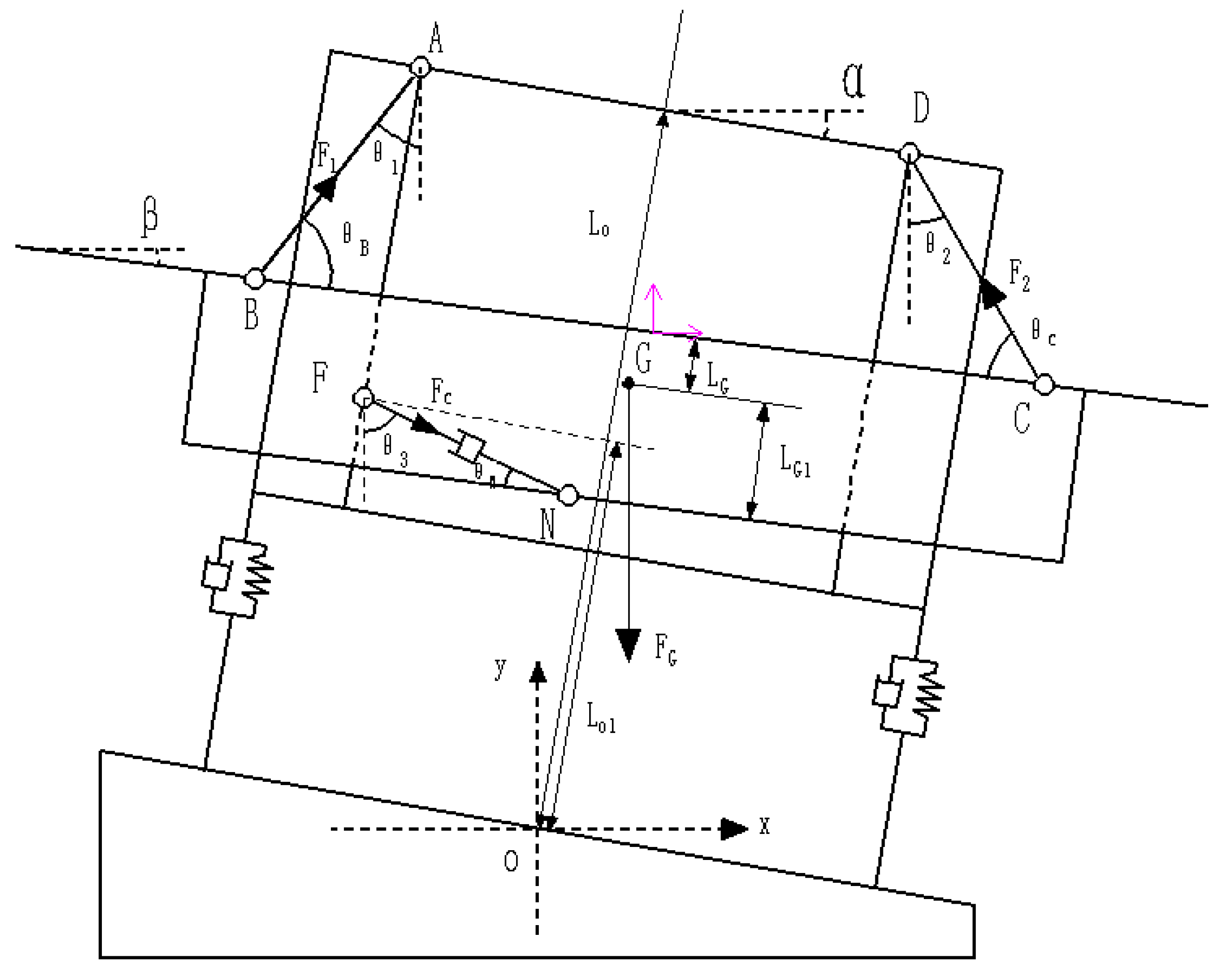
Based on the above assumptions, the force analysis of the boom suspension is shown in Figure 2.
As shown in Figure 2, the hinge points on the inner and outer boom suspension are A, B, C, D four points, and the outer boom suspension is connected to the inner boom suspension by connecting rods AB and CD. The center of gravity of the outer boom suspension and the boom suspension on both sides is G, and the equivalent damping composed of the hydraulic cylinder and the throttle hole is hinged between the inner and outer boom suspension, and the handover points are F and N. To simplify the mathematical model, it is assumed that the sprayer fuselage rotates around a fixed axis parallel to the direction of the locomotive and through point O. The mathematical model is as follows:
x = L A D 2 cos α + L 0 sin α L A B sin θ 1 + L B C 2 cos β L G sin β x = L A D 2 cos α + L 0 sin α L C D sin θ 2 L B C 2 cos β L G sin β
y = L 0 cos α + L A D 2 sin α L A B cos θ 1 L B C 2 sin β L G cos β y = L 0 cos α L A D 2 sin α L C D cos θ 1 + L B C 2 sin β L G cos β  
where LAD is the length of suspension rod AD (m); LAB is the length of suspension rod AB (m); LBC is the length of suspension rod BC (m); LCD is the length of suspension rod CD (m); LO is the length of the suspension to the center of gravity; α is the angle of inclination of the body (rad); β is the angle of inclination of the boom (rad); and LG is the length of the rod BC to the center of gravity.
The initial values of the angle θ1, θ2 between the connecting rod AB, CD, and the vertical direction is
θ ¯ = sin 1 L B C L A D L A B + L C D
Due to the α, the β change values are small; then, there are the following:
sin α = α ,   sin β = β cos α = 1 α 2 2 ,   cos β = 1 β 2 2 sin θ 1 = sin θ ¯ + Δ θ 1 cos θ ¯ cos θ 1 = cos θ ¯ Δ θ 1 sin θ ¯ sin θ 2 = sin θ ¯ + Δ θ 2 cos θ ¯ cos θ 2 = cos θ ¯ Δ θ 2 sin θ ¯
With the simultaneous (1)–(4) derivation, and ignoring the second-order small quantity, the center of gravity G coordinates are obtained:
x ˙ = L 0 + cos θ ¯ 2 sin θ ¯ L A D α ˙ cos θ ¯ 2 sin θ ¯ L B C + L G β ˙
x ¨ = L 0 + cos θ ¯ 2 sin θ ¯ L A D α ¨ cos θ ¯ 2 sin θ ¯ L B C + L G β ¨
y ˙ = 0
y ¨ = 0
According to the coordinates (xF, yF) and (xN, yN) of the connection points F and N of the equivalent damper [20], the damping force of the equivalent damper can be obtained as follows:
F c = 8 L F N 2 A 3 ρ C d 2 π 2 d 4
where LFN is the speed of change in damping (m·s−1); A is the effective working area of hydraulic cylinders (m2); ρ is the oil density (kg·m−3); Cd is the flow coefficient; and d is the throttle diameter (m).
M B x ¨ = F 1 sin θ 1 F 2 sin θ 2 + F C sin θ 3 M B y ¨ = F 1 cos θ 1 F 2 cos θ 2 F C sin θ 3 M B g I B β ¨ = F 1 L G cos θ B + L B C 2 sin θ B F 2 L G cos θ c + L B C 2 sin θ c F C L G 1 cos θ N
According to the planar D’Alembert’s principle, the following is obtained:
where F1 is the force experienced by the connecting rod AB (N); F2 is the force experienced by the connecting rod CD (N); MB is the sum of the masses of the outer boom suspension and the boom suspension on both sides (kg); and θB, θC is the angle between the connecting rod AB, CD, and the outer boom suspension (rad).
θ B = π 2 θ 1 + β θ C = π 2 θ 2 + β
By combining Equations (3)–(11), the following mathematical formulas are obtained:
F 1   =   M B g sin θ 2   +   cos θ 2 M B x ¨     F C ( sin θ 3 cos θ 2     cos θ 3 sin θ 2 ) cos θ 1 sin θ 2   +   sin θ 1 cos θ 2 F 2   =   M B g sin θ 1     cos θ 1 M B x ¨   +   F C ( sin θ 1 cos θ 3   +   cos θ 1 sin θ 3 ) cos θ 2 sin θ 1   +   sin θ 2 cos θ 1
From the above analysis, it can be seen that the quality of the boom suspension is only related to the mechanism design and suspension material, so MB is a constant parameter and is not considered as a relevant variable. And the influence of θ1 on Fc is very small, so θ1 is set as a fixed value, and its influence on the inclination angle of the boom suspension is not considered. Therefore, there are four main influencing factors affecting the inclination angle of the boom suspension, namely, the length of the rod member LAD of the inner boom suspension, the length of the rod on the outer boom suspension LBC, the length of the connecting rod LAB, and the diameter of the throttle diameter d.
f = [LAD   LBC   LAB   d]T
Influencing factor f can be expressed as follows:

2.2.2. Optimize the Establishment of Mathematical Model

In order to meet the design criteria of the boom suspension, the maximum sinusoidal excitation of 10 rad/s is used as the environmental excitation of the fuselage. The spray bar suspension is designed with 0~10 rad/s as the fuselage excitation, so the objective function is the minimum value of the inclination angle, then the objective function is as follows:
F ( f ) = m i n ( β )
In this study, the natural frequency of the boom suspension is set to 0.7~1.3 rad/s with reference to the method of designing the boom suspension by Chen et al. [23]. And in order to ensure a great follow-up performance of the low-frequency environmental excitation of the boom suspension and isolation performance of the high-frequency environmental excitation, the natural frequency wn of the boom suspension can be set to
ω n ( 0.7 ~ 1.3 )
In order to ensure that the service life of the boom suspension after optimization meets the requirements, the boom suspension should meet the following requirements:
σ σ
where σ is the maximum stress of the boom suspension (KPa); [σ] is the allowable stress of the boom suspension (KPa).
In summary, the final optimized mathematical model of the boom suspension can be expressed as follows:
min β = f L A D     L B C     L A B     d ω n ( 0.7 ~ 1.3 ) σ σ

2.2.3. Construction of 3D Model of Boom Suspension

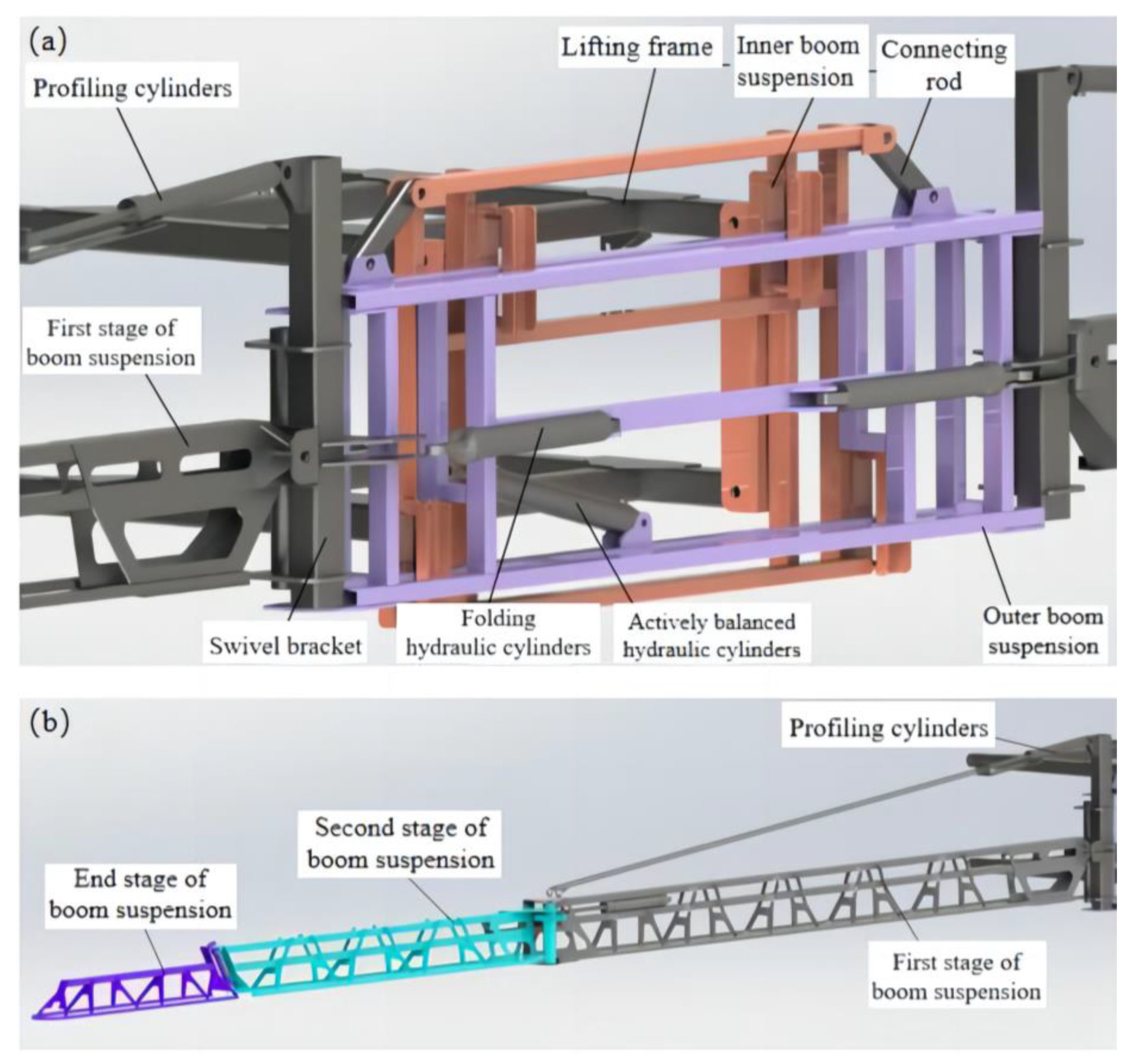
In this study, a 3D model of the two-link trapezoidal boom suspension of the 3WPYZ sprayer is constructed based on SolidWorks
The main structural parameters and the cross-sectional shape and wall thickness of each component of the boom suspension are shown in Table 1 and Table 2.
The constraints between the assemblies are completed according to the position relationship and motion relationship required by the design.
Most of the boom suspension is designed with a thin-walled beam structure, and its main material is Q235. In the design process, the outer boom suspension is required to isolate the vibration transmitted by the inner boom suspension, and the boom suspension and the rotating bracket on both sides should complete the deployment and folding functions of each section in the work. Cylindrical connections are used between each section of the boom and between the boom and the hydraulic cylinder; a 3D model of the two-link trapezoidal boom suspension is shown in Figure 3.

2.3. Dynamic Characterization Simulation Test Process Based on ADAMS

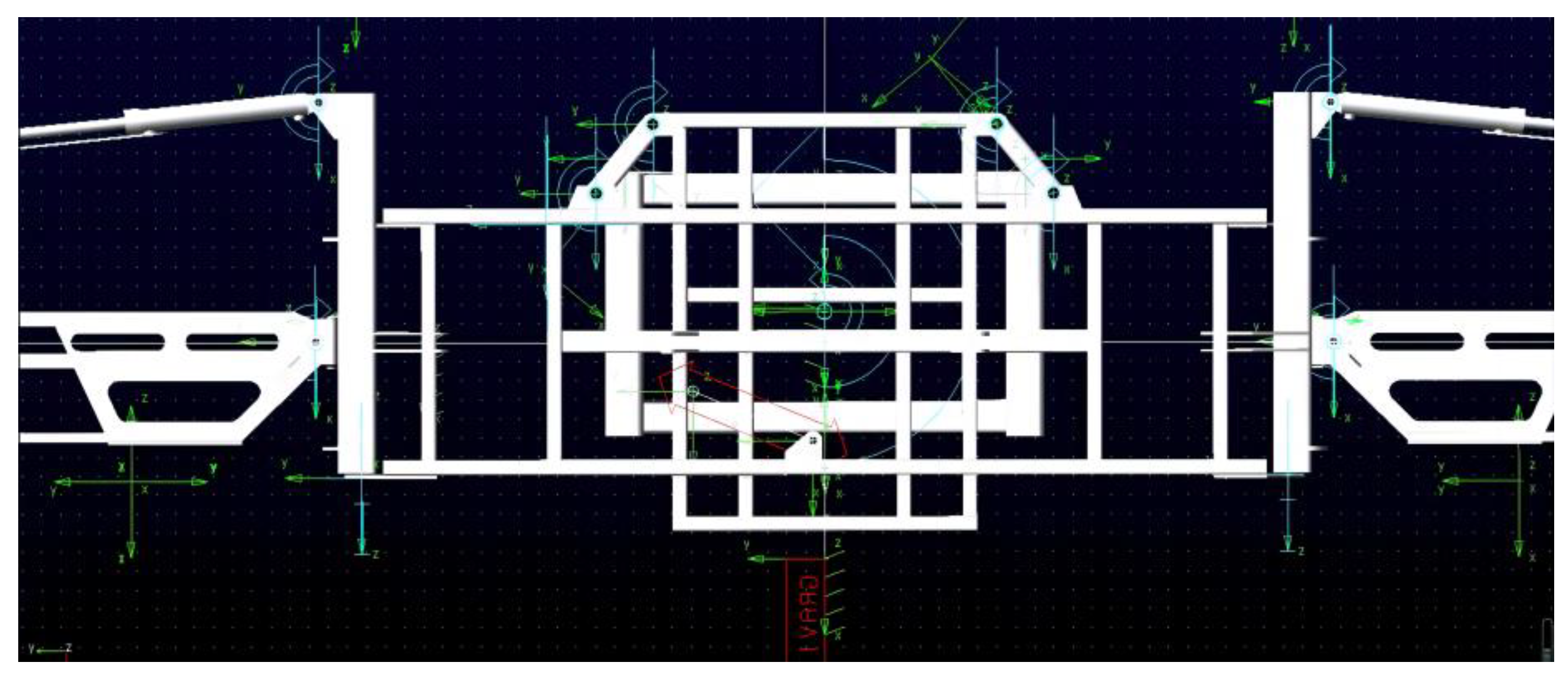
In this study, ADAMS 2020 (Automatic Dynamic Analysis of Mechanical Systems) software is used to simulate the influence of environmental factors on the actual working process of the boom suspension, which provides a basis for the optimization of the boom suspension. After the drawing file is imported into the ADAMS file, the base system of the units is set to MMKS and the acceleration of gravity in the X-axis direction is set to 9.8 m/s2. The mass density of each component material is set to steel (the value is 7.801 × 10⁶ kg/mm3, the Young’s modulus of elasticity is set to 2.07 × 10³ N/mm2, and the Poisson’s ratio is set to 0.29. The virtual prototype model is obtained by adding constraints, drives, and element forces to the virtual prototype, as shown in Figure 4.

2.4. Static Analysis Simulation Test Process Based on Ansys

A 3D model of the two-link trapezoidal suspension is imported into Ansys Workbench 14.0 software and the coordinates are maintained in a directionally consistent manner. The overall structural material of the boom suspension is set to Q235. The material of the hydraulic cylinder is set to 45#. As shown in Figure 5, the automated method was chosen for model meshing. In total, 545,238 nodes and 341,139 elements were obtained after the automatic meshing process. When the grid was 300,000 to 500,000, the data varied considerably. But when the mesh count was 500,000 to 800,000, the data difference was less than 5%. Therefore, a number of grids of 500,000 was chosen in this article. The grid was tested for independence.

2.5. Field Dynamic Characteristic Test Process

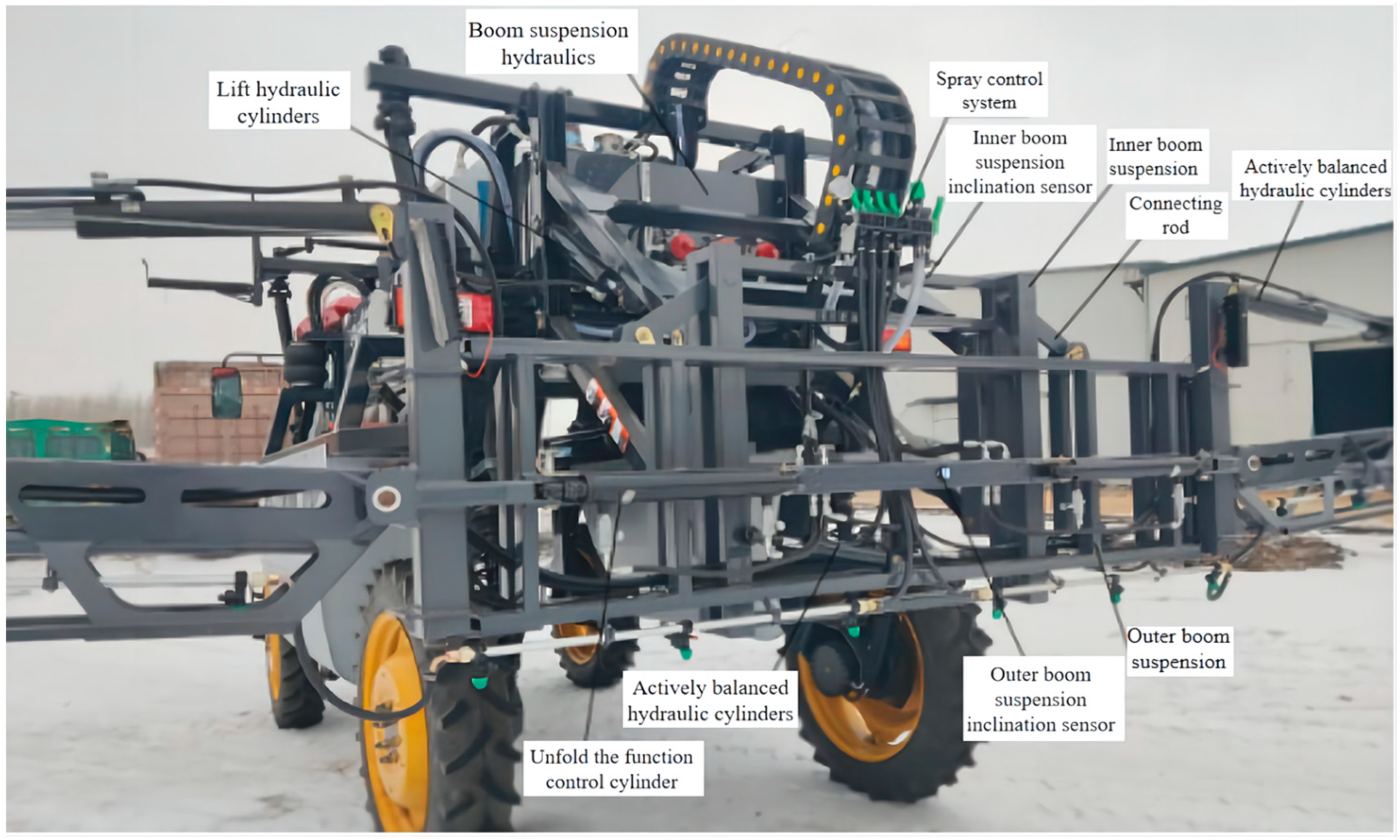
In order to verify the operation performance of the optimized design of the boom suspension and the reliability of various parameters, combined with theoretical analysis and simulation, a WT901C485 angle sensor, produced by Shenzhen Witt Intelligent Technology Co. Ltd., was installed on the boom suspension to measure the dynamic characteristics of the boom suspension under working conditions (Figure 6), and the 3WPYZ self-propelled sprayer was used as the carrier for field experiments. The angle sensor measures acceleration with an accuracy of 0.01 g and an angular velocity of 0.05 rad/s.
The test section was set to a 125 m field section, and since the speed of the vehicle cannot be fully controlled during field operations, in order to reduce the error value, a 50 m starting road section was set, and the sensor was used to start sampling data after the speed was stable. According to the sprayer’s manual, the sprayer’s driving speed was set to 10 km/h for testing, and combined with the agricultural requirements of corn field operations; the ground clearance of the boom suspension was changed to 500 mm, 1200 mm, and 2500 mm. The inclination angle sensor installed on the boom suspension and the single-sided boom suspension installed in the high gap self-propelled sprayer were used to test and record the angle change in the suspension during the movement 3 times.

3. Results and Discussion

3.1. Dynamic Simulation Results and Analysis

3.1.1. Step Excitation Response Analysis

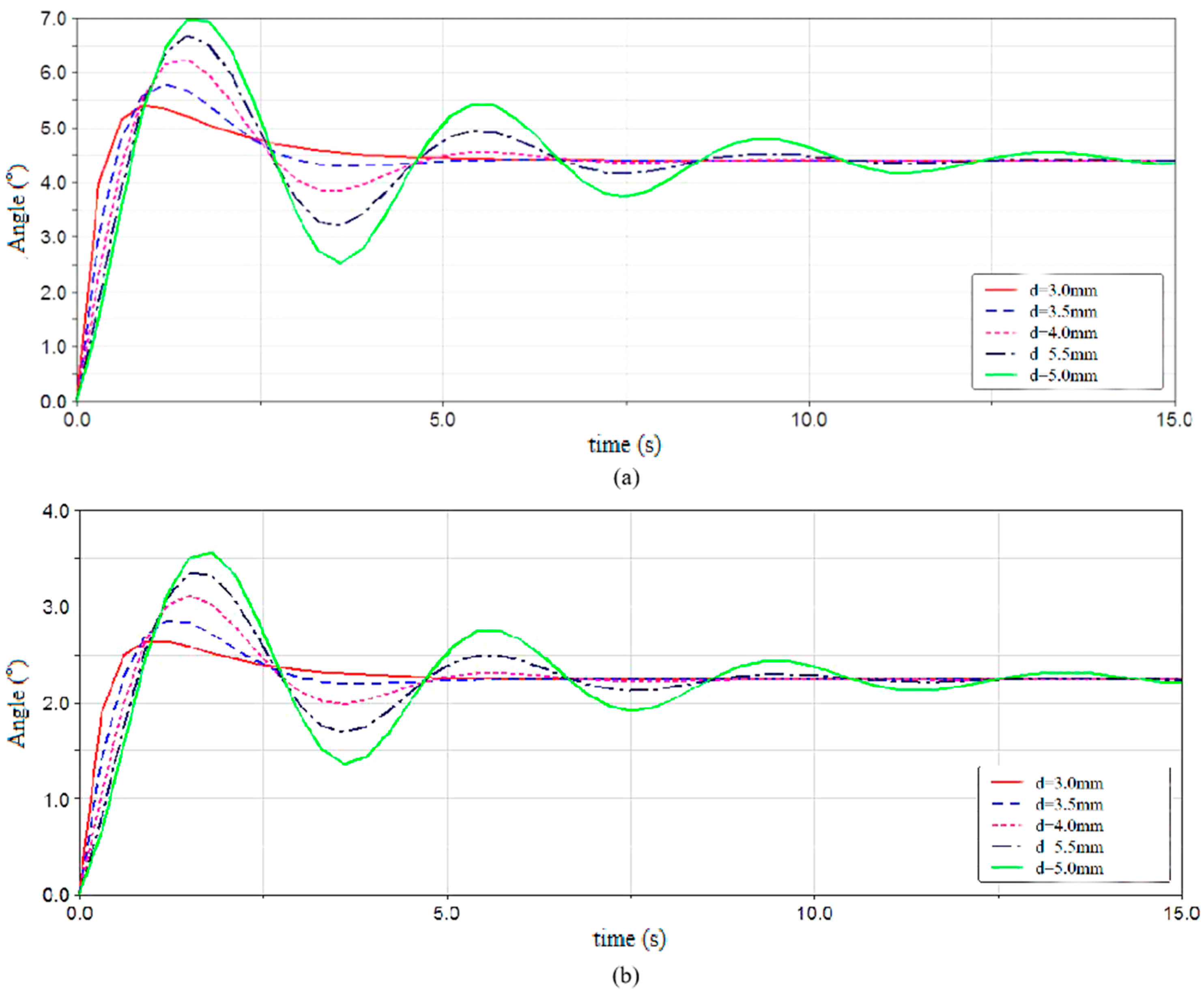
Since the step signal has the most obvious effect on the excitation of the system, the drive was first set as the step excitation signal to test the response of the boom suspension. The simulation time was set to 15 s, the simulation step was set to 500, and the driver function was set to STEP( time, 0, 0, 0.01, 1) * 5d. The diameter of the orifice d of the equivalent damper was set to five parameters for the simulation test, and 2.5°and 5°were input as amplitudes, as shown in Figure 7.
As can be seen from Figure 7, the change in the equivalent damping force of the system has a great influence on the vibration of the boom suspension. When the diameter of the orifice d was increased, the damping force of the system was reduced, the peak step response of the boom suspension became larger, and the number of oscillations increased. When the diameter of the orifice d was smaller, that is, the system damping force was larger, the boom suspension was smoothed out faster and the response speed of the boom suspension was faster.

3.1.2. Sinusoidal Excitation Response Analysis

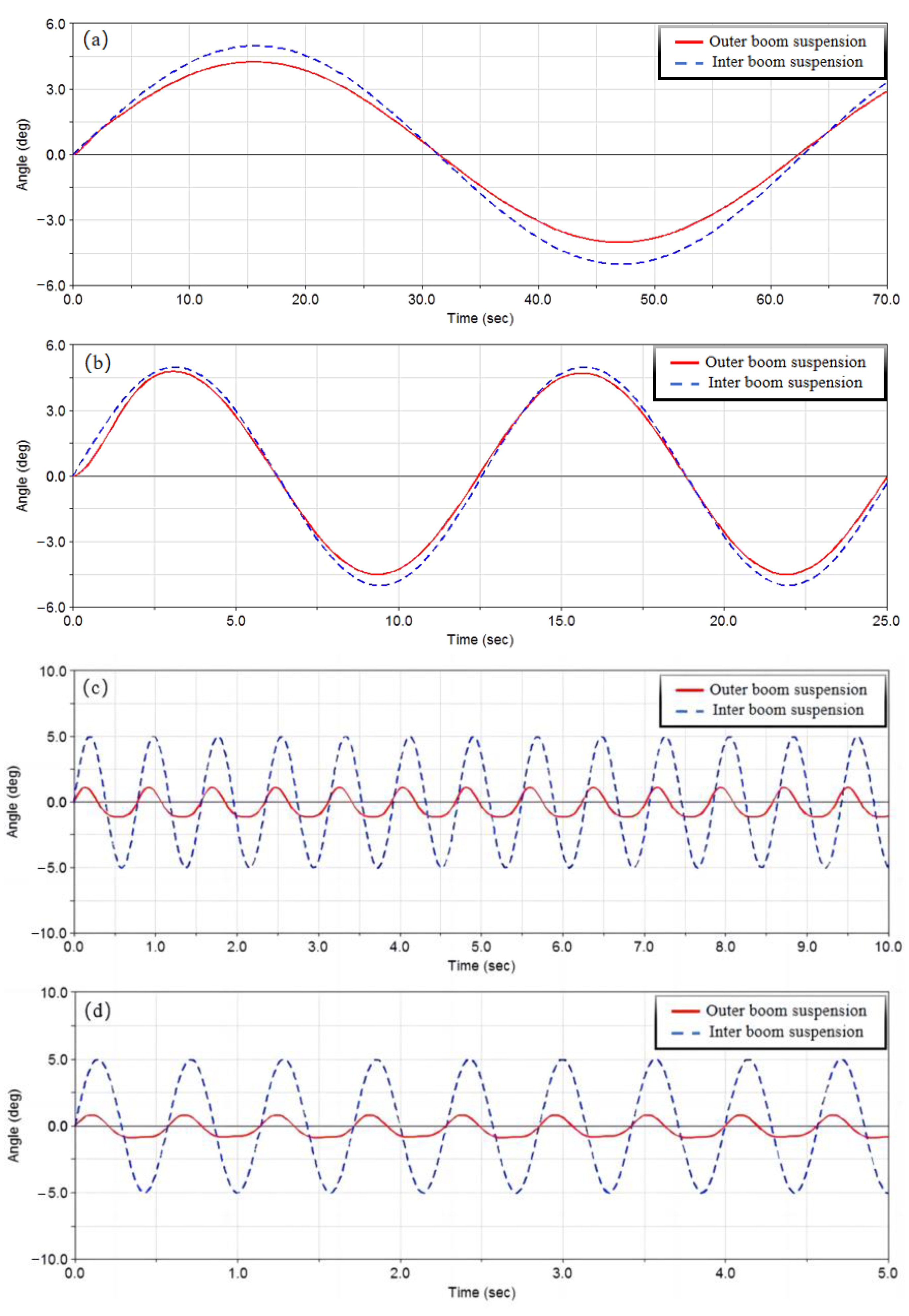
The drive was set to a sinusoidal excitation y = A s i n ω t , where w is the angular frequency, A is the amplitude, and t is the time. In this study, the amplitude A was set to 5° and the angular frequency was changed to obtain the dynamic characteristics of the boom suspension at w = 0.1 rad/s, 0.5 rad/s, 5 rad/s, and 10 rad/s, as shown in Figure 8.
It can be seen from Figure 8 that the inner nozzle suspension was stimulated by the external low-frequency sinusoidal excitation w = 0.1 rad/s; this was w = 0.5 rad/s for sinusoidal motion and the outer boom suspension followed the inner boom suspension. When w = 10 rad/s, the maximum swing angle of the inner boom suspension was 5°, and the maximum value of the outer boom suspension was 0.877°. The spray bar suspension designed this time can follow the movement of the body when encountering low-frequency excitation and isolate the vibration transmitted by the body when encountering high-frequency excitation, but the isolation effect needs to be further improved.

3.1.3. Virtual Trials of Boom Suspensions

In order to optimize the isolation effect of the boom suspension when the locomotive encounters high-frequency excitation, ADAMS is used to perform the single factor tests of LAD, LBC, LAB, and orifice diameter d. By changing the single influencing factor, the influence of each influencing factor on the maximum oscillation degree and natural frequency was obtained, and the existence range of the optimal solution was determined.
(1)
Change the length of the inner boom suspension rod LAD
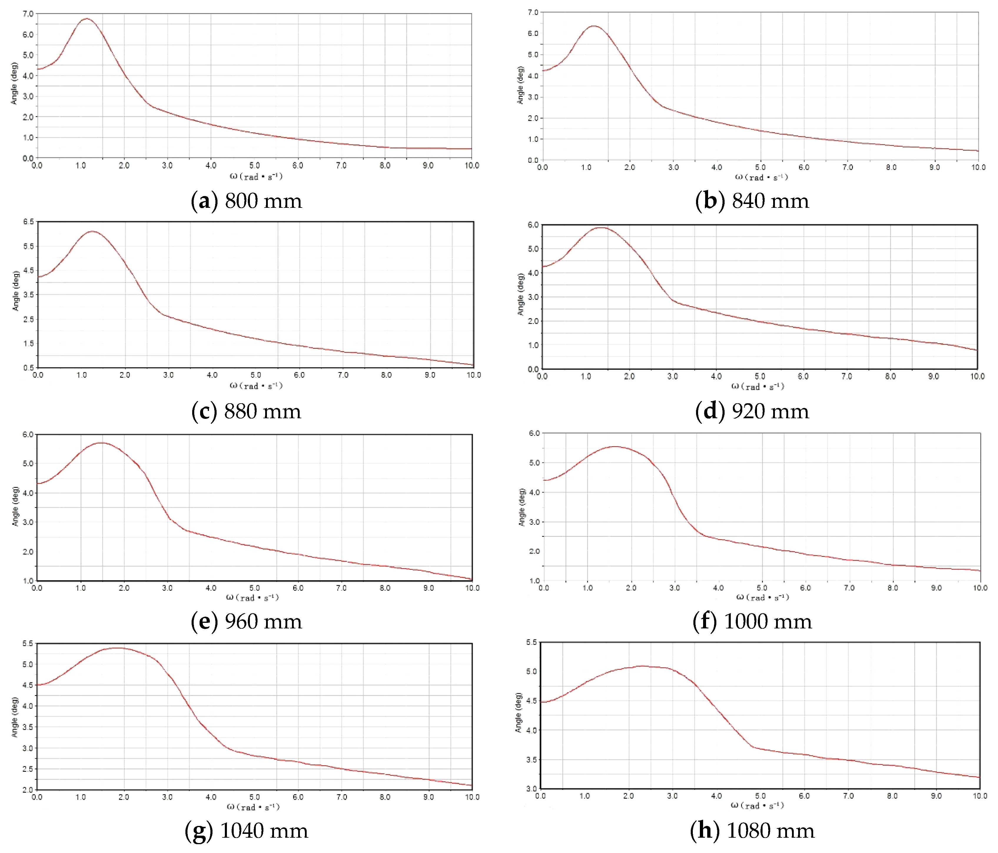
The amplitude was set to 5°, and the driving sinusoidal excitation signal was set to 0~10 rad/s. By changing the size parameters of the LAD, in the range of 800~1080 mm, eight values were taken with an interval of 40 mm. The dynamic simulation analysis of different boom suspension models is shown in Figure 9.
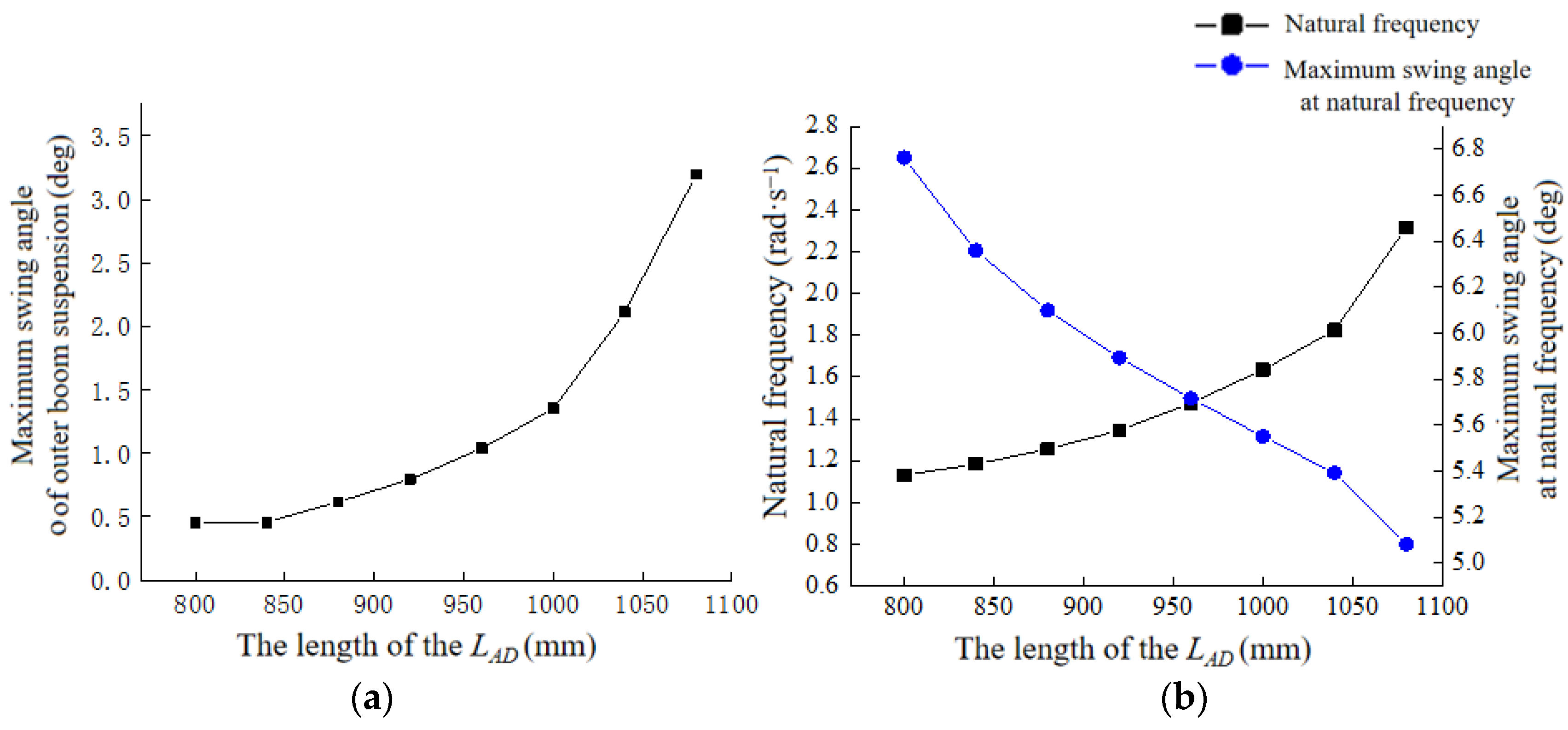
Due to the nature of natural frequencies, the highest inflection point in Figure 10a is the natural frequency. When w was less than the natural frequency, the boom suspension was able to follow the oscillation of the body. When w was greater than the natural frequency, the boom suspension began to isolate the vibration transmitted by the body and the maximum swing angle of the outer boom suspension gradually decreased as the frequency continued to increase. As can be seen from Figure 10b, with the increase in LAD, the natural frequency gradually increased, and the swing angle of the outer boom suspension at the natural frequency gradually decreased. When the size of the LAD exceeded 1040 mm, the swing angle of the boom suspension changed very little, close to the swing angle of the fuselage. The results show that, when the LAD of the boom suspension exceeded 1040 mm, the boom suspension followed the fuselage when stimulated by the external high frequency and low frequency, which does not meet the design requirements. Therefore, the LAD was selected in the range of 840~1000 mm.
(2)
Change the length of the inner boom suspension rod LBC, LAB, and d
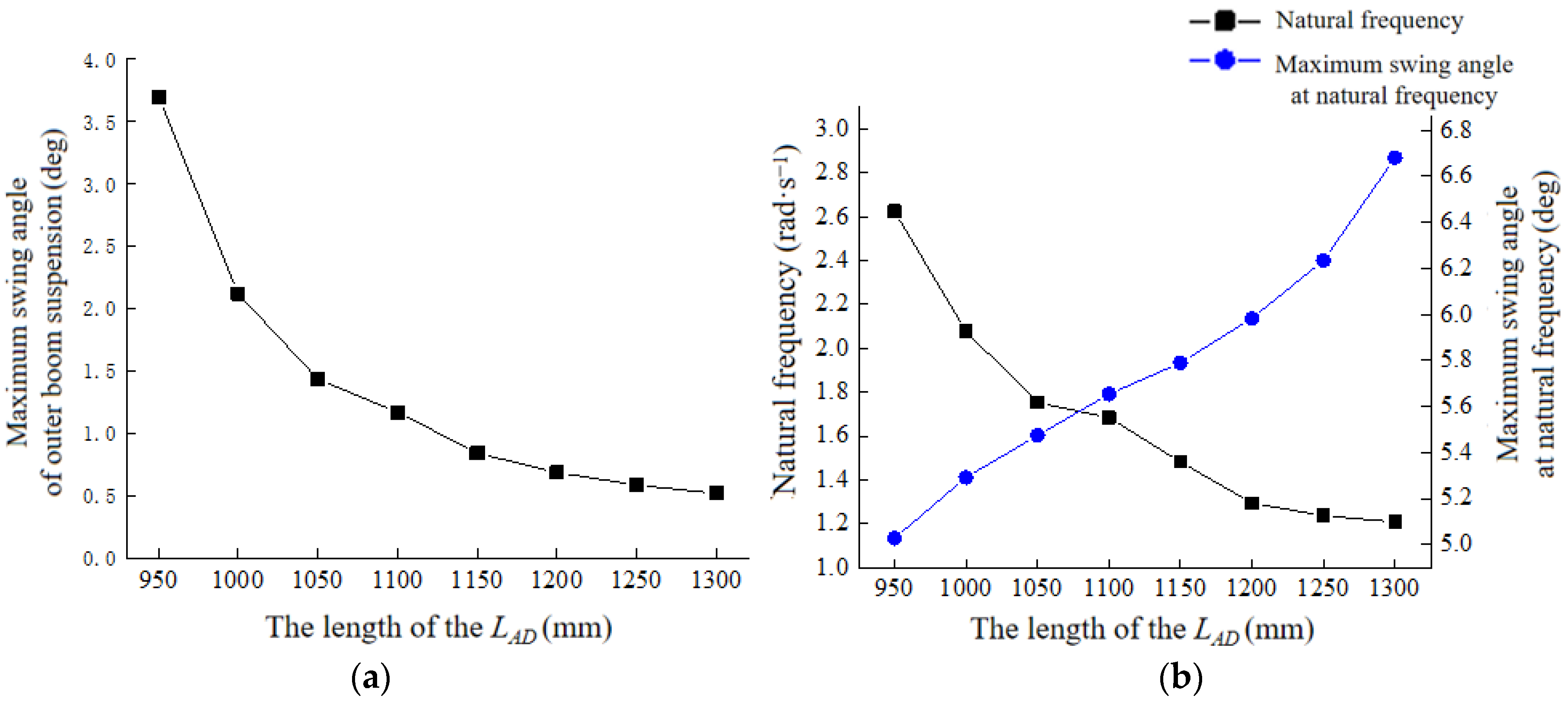
A similar method was used to perform dynamic simulation analysis by changing the length of LBC, LAB, and d. The amplitude was set to 5°, and the driving sinusoidal excitation signal was set to 0~10 rad/s. By changing the size parameters of the LBC, in the range of 950~1300 mm, eight values were taken with an interval of 50 mm. The kinematic simulation analysis of different boom suspension models is shown in Figure 11.
The amplitude was set to 5°, and the driving sinusoidal excitation signal was set to 0~10 rad/s. By changing the size parameters of the LAD, in the range of 190~280 mm, seven values are taken with an interval of 15 mm. The kinematic simulation analysis of different boom suspension models is shown in Figure 12.
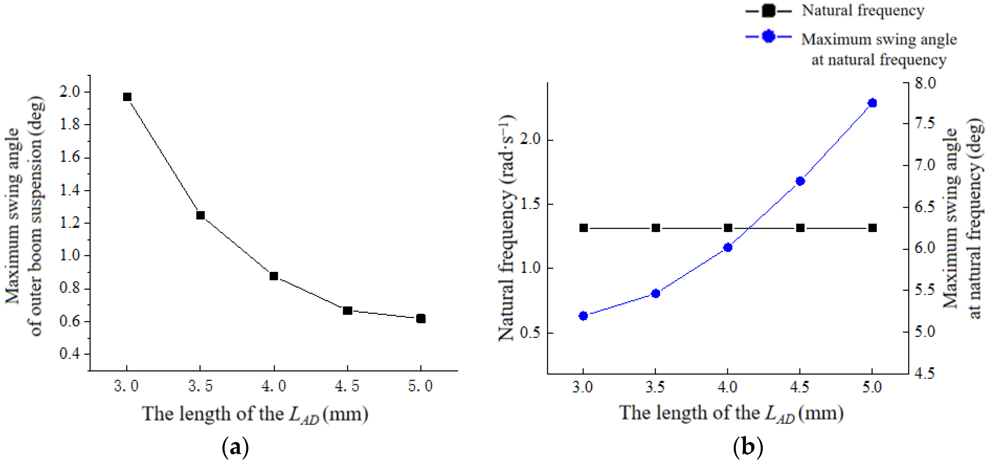
The amplitude was set to 5°, and the driving sinusoidal excitation signal was set to 0~10 rad/s. By changing the size parameters of the d, five values were taken with an interval of 0.5 mm. The kinematic simulation analysis of different boom suspension models is shown in Figure 13.
According to the above test results, the factor level coding table of the multivariate orthogonal test was determined, as shown in Table 3.
In this paper, the L25(56) orthogonal table was selected for the experimental design, and the extra two factors in the table were set as empty columns to estimate the experimental error and improve the accuracy of the experiment. The test protocol and results are shown in Table 4.
A variance analysis of the simulation data was carried out using Design-Export software 8.0.6, and the results of the ANOVA analysis of the influencing factors on the swing angle and natural frequency are shown in Table 5 and Table 6.
From the above results, it can be seen that LBC, LAD, and orifice diameter d have extremely significant effects on the swing angle of the external spray bar suspension. The influence of LBC and LAD on the natural frequency was very significant, the orifice diameter d had little influence on the change in natural frequency, and the influence of LAB on the swing angle and natural frequency was small. The influence of the four factors on the swing angle of the external boom suspension was LBC(B) > LAD(C) > d(D) > LAB(A), and the influence of the natural frequency of the boom suspension was LBC(B) > LAD(C) > LAB(A) > d(D). Using the data filtering function of the software, the minimum values of the swing angle and the natural frequency between 0.7 and 1.3 rad/s were set, and the results are shown in Table 7.
Group 1, with the smallest swing angle, was selected as the final optimal design scheme. The length of the connecting rod of the final scheme was LAB = 265 mm, the length of the inner spray rod suspension was LAD = 840 mm, the length of the outer spray rod suspension was LBC = 1250 mm, and the diameter of the throttle hole was d = 4 mm.
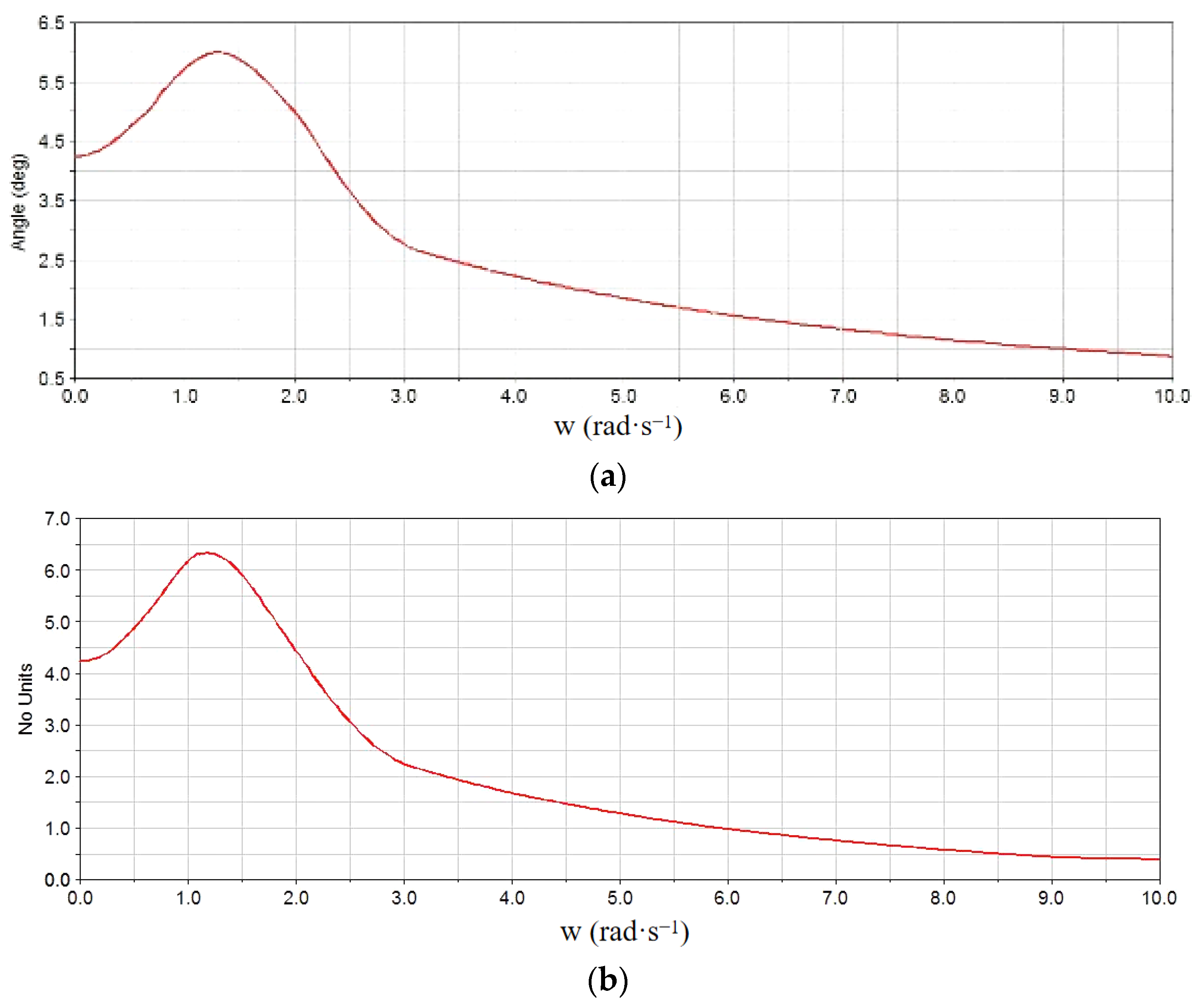
The ADAMS model was constructed using the optimized structure size, the same constraints and drivers were set for the single-factor test to simulate the dynamic of the optimized model, and the results were analyzed; the results are shown in Figure 14.
Comparing the above figure, it can be seen that the maximum swing angle and natural frequency after optimization are basically consistent with the predicted values of Design-Expert. After optimization, the maximum swing angle of the boom suspension decreased significantly, and the maximum swing angle was 0.877° before optimization ω = 10 rad/s, and the maximum swing angle was 0.412° after optimization, which decreased by 53.02% compared with that before optimization. The natural frequency was reduced from 1.3143 rad/s to 1.1826 rad/s, which met the design requirements. The optimization scheme in this study satisfies the requirements of reducing the maximum swing angle and improving the structure so that the natural frequency is between 0.7 and 1.3 rad/s.

3.2. Static Simulation Results and Analysis

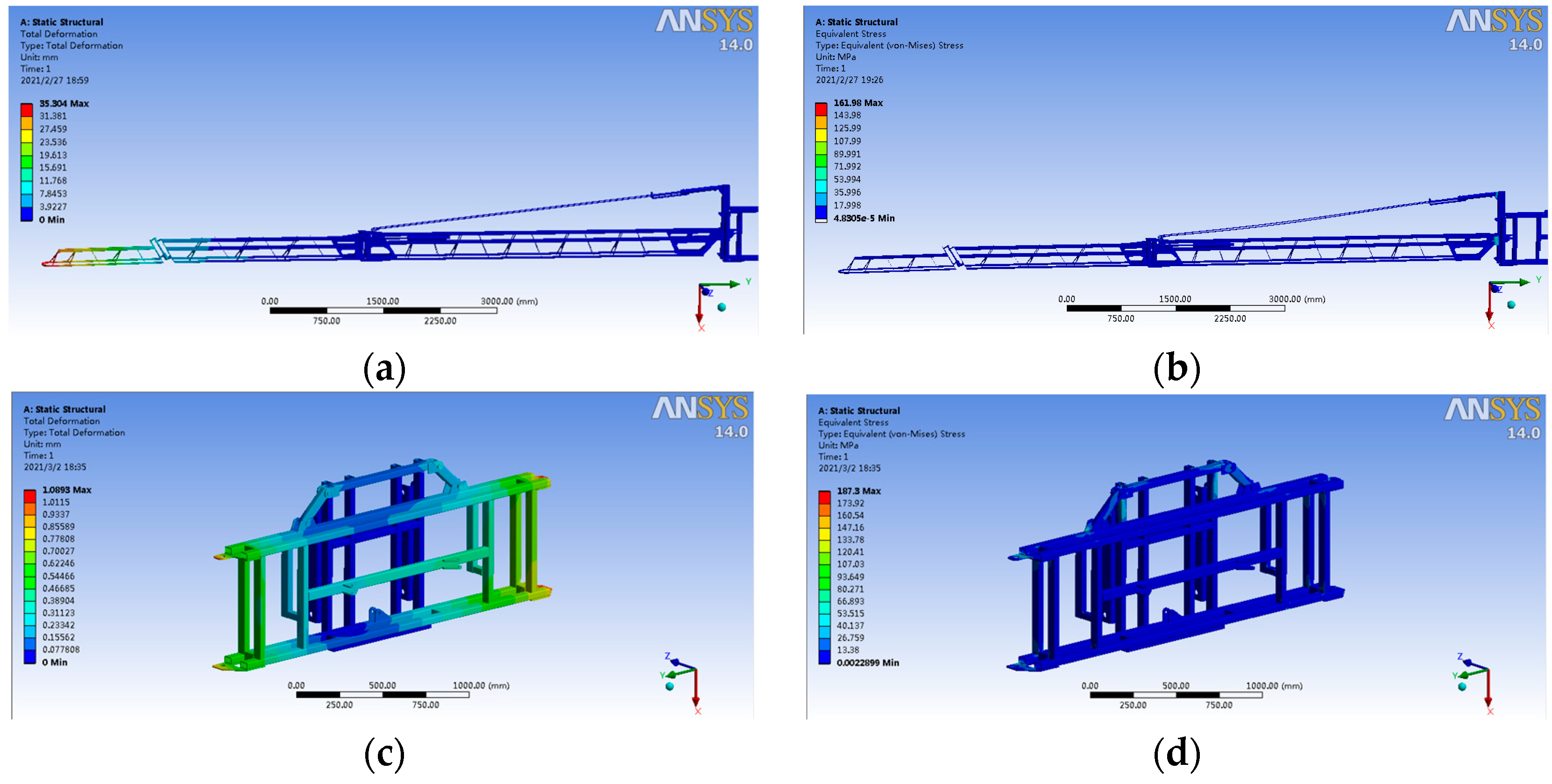
As shown in Figure 15, it can be seen that the maximum stress of the connecting plate in the first section of the boom suspension was 54.97 MPa, well below the yield limit. The maximum displacement of the boom suspension was only 2 mm, close to zero. However, the maximum displacement of 35.304 mm occurred in the third section. The contact area between the inner sprayed high connecting plate and the vertical beam was small, leading to an intense local stress of 128.36 MPa. Therefore, both boom suspensions mentioned in this article need to be optimally designed. We planned to add torsion spring to the joints, which ensured the stability of the spraying process.
The first six natural frequency analysis of the boom suspension under the modal module of ANSYS 14.0 (Figure 16).
According to the analysis results shown in Figure 16, the natural frequencies of the first six modes of the spray suspension designed in this paper were in the range of 4.26~26.62 Hz. In the field test, even if the external ground was uneven and caused the body to sway, it could still ensure stable operation under the profiling function of the active suspension.

3.3. Field Performance Test Results and Analysis

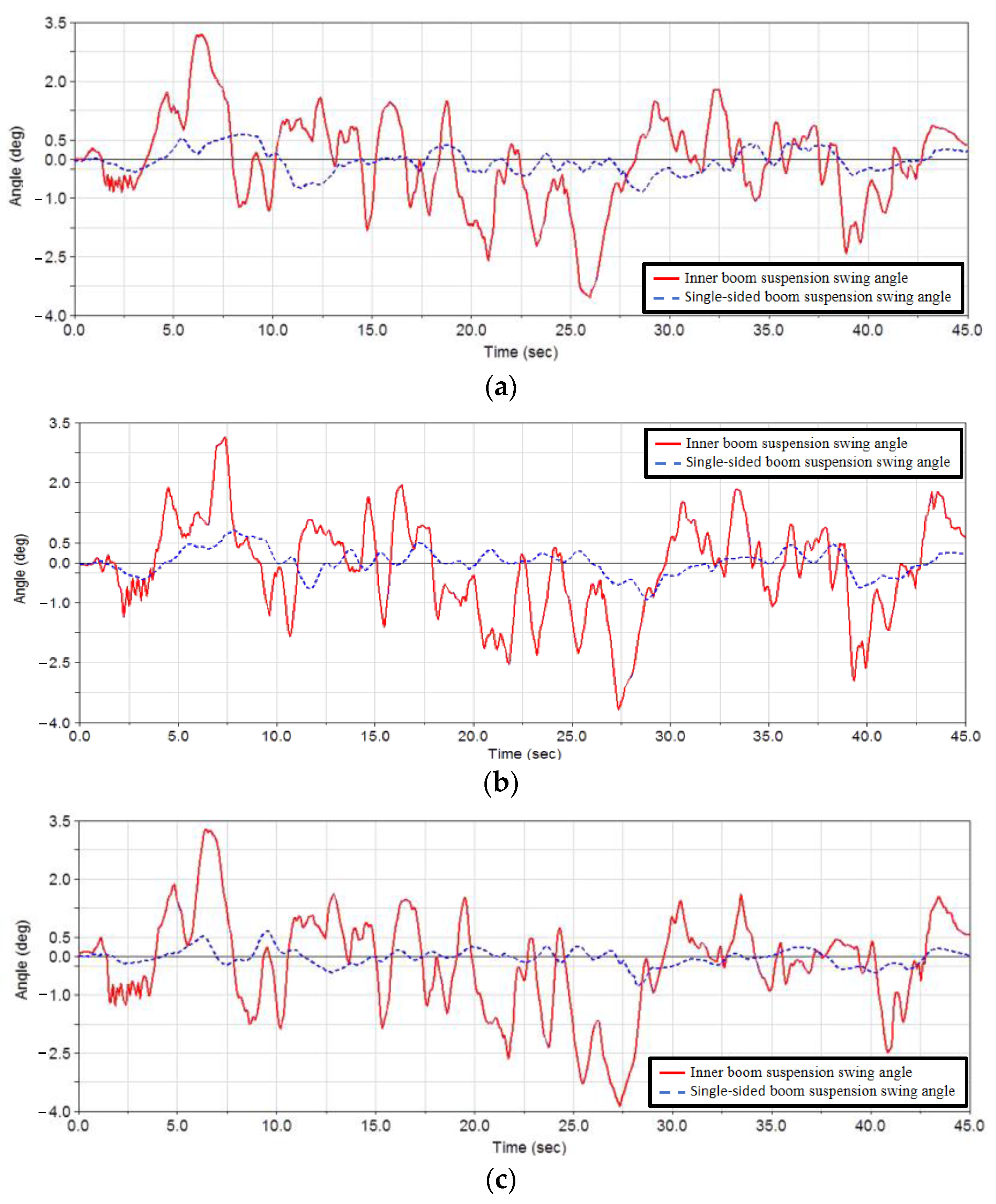
The swing angle of the inner boom suspension and the swing angle curve of the one-side boom suspension are shown in Figure 17. Table 8 shows the maximum swing angles in the forward and reverse directions of the three suspension heights.
It can be seen from Figure 17 that the environmental excitation of the sprayer was 3.5~4°, and with the increase in the height of the sprayer boom suspension, the overall change curve of the inner boom suspension changed obviously, and the maximum swing angle in the forward and reverse directions was approximate. There was no obvious change in the overall curve of the single-sided boom suspension, and the height of the boom suspension increased. The angle between the hoist and the vertical direction increased first and then decreased, the maximum swing angle of the suspension increased first and then decreased, and the change range was about 0.2°, which proves that the mathematical model is reasonable. The maximum swing distance at the end of the 21 m boom was only 0.073 m, which ensured the stability of the pesticide application operation.
It can be seen from Table 9 that the overall change curve of the single-side boom suspension was relatively stable, and the boom suspension can realize the effect of isolating the vibration transmitted by the fuselage under different test conditions, which meets the design requirements.

4. Conclusions

Based on the 3WPYZ high gap self-propelled sprayer, this study designed a boom suspension system that can achieve the requirements of large width, low stiffness and weak damping, and vibration reduction. On the basis of considering the structural layout of the sprayer and the parameters of the boom, the dynamic characteristics and static analysis of the boom suspension system were analyzed, and the rationality of the optimization was verified by field tests. The research conclusions are as follows:
(1)
Based on the D’Alembert principle and the principle of multibody dynamics, a kinematic model of a two-link trapezoidal boom suspension was established, and the design factors affecting the stability of the boom were determined through theoretical analysis.
(2)
The results of the multi-factor test based on Design-Expert show that, when the connecting rod length LAB was 265 mm, the inner boom suspension rod LAD was 840 mm, the outer boom suspension rod LBC was 1250 mm, and the throttle diameter d was 4 mm; the maximum swing angle of the nozzle suspension decreased by 53.02%, the natural frequency decreased from 1.3143 rad/s to 1.1826 rad/s, and the dynamic characteristics were significantly optimized.
(3)
After static optimization, the stress at the joint of the boom suspension was reduced to 22 MPa, the maximum displacement was reduced to 7 mm, and the maximum stress of the inner boom suspension was reduced to 88.07 MPa. The modal analysis results show that the optimized design of the boom suspension can effectively avoid the influence of external swing frequency on the stability of the suspension.
(4)
The angle between the hoist and the vertical direction increased first and then decreased, and the maximum swing angle of the suspension increased first and then decreased; the change range was about 0.2°, which proves that the mathematical model is reasonable. The maximum swing distance at the end of the 21 m boom was only 0.073 m, ensuring the stability of the pesticide application operation.

Author Contributions

J.H. and C.L. conceived the idea of the experiment; Y.L. and C.L. performed the field test; Y.L. and C.L. analyzed the data; and Z.Y., C.L., S.Z., Q.L. and W.Z. wrote and revised the paper. All authors have read and agreed to the published version of the manuscript.

Funding

This research was funded by the Heilongjiang Province Applied Technology Research and Development Program Project (No. GA21B003), the National Soybean Industry Technology System Post Expert Project (CARS-04-PS30), the Heilongjiang Provincial Natural Science Foundation Joint Guidance Project (LH2023E106), the Heilongjiang Province key research and development plan (2023ZX01A06) and the Jiusan Soybean Industry Innovation Research Institute Project (2022402).

Institutional Review Board Statement

Not applicable.

Data Availability Statement

Restrictions apply to the availability of these data. Data were obtained from the Heilongjiang Agricultural Reclamation Agricultural Machinery Test and Appraisal Station and are available from Zhaonan Yu with the permission of the Heilongjiang Agricultural Reclamation Agricultural Machinery Test and Appraisal Station.

Conflicts of Interest

The authors declare no conflicts of interest.

References

  1. Hu, Y.H.; Yang, H.B.; Hou, B.R.; Xi, Z.T.; Yang, Z.D. Influence of Spray Control Parameters on the Performance of an Air-Blast Sprayer. Agriculture 2022, 12, 1260. [Google Scholar] [CrossRef]
  2. He, X. Advances in high efficiency plant protection machinery and precision application technology. J. Plant Prot. 2022, 49, 389–397. (In Chinese) [Google Scholar]
  3. Feng, Y.N.; Pei, L.; Chen, X.; Chen, X.B.; Liu, Y.; Chen, B. Summary of the key technology of variable rate application. J. Chin. Agric. Mech. 2021, 42, 65–71. [Google Scholar]
  4. Luo, X.W.; Liao, J.; Hu, L. Improving agricultural mechanization level to promote agricultural sustainable development. Trans. Chin. Soc. Agric. Eng. 2016, 32, 1–11. (In Chinese) [Google Scholar]
  5. Li, W.; Yang, F.; Mao, E.R.; Shao, M.X.; Sui, H.C.; Du, Y.F. Design and Verification of Crab Steering System for High Clearance Self-Propelled Sprayer. Agriculture 2022, 12, 1893. [Google Scholar] [CrossRef]
  6. He, X. Research and development of crop protection machinery and chemical application technology in China. Chin. J. Pestic. Sci. 2019, 21, 921–930. [Google Scholar]
  7. Zhang, G. Research and Design of Four Wheel Steering System of High Clearance Self-Propelled Platform; Northwest A&F University: Yangling, China, 2016. [Google Scholar]
  8. Sartori, S.; Balthazar, J.M.; Pontes, B.R. Non-linear dynamics of a tower orchard sprayer based on an inverted pendulum model. Biosyst. Eng. 2009, 103, 417–426. [Google Scholar] [CrossRef]
  9. Cui, L.F.; Xue, X.Y.; Le, F.X. Adaptive robust precision control of an active spray boom suspension with disturbance estimation. J. Vib. Control 2021, 29, 3–4. [Google Scholar] [CrossRef]
  10. Han, J.H.; Park, C.H.; Jang, Y.Y.; Gu, J.D.; Kim, C.Y. Performance Evaluation of an Autonomously Driven Agricultural Vehicle in an Orchard Environment. Sensors 2022, 22, 114. [Google Scholar] [CrossRef]
  11. Li, W.; Xue, T.; Mao, E.; Du, Y.; Li, Z.; He, X. Design and Experiment of Multifunction Steeering System for High Clearance Self-propelled Sprayer. Trans. Chin. Soc. Agric. Mach. 2019, 50, 141–151. [Google Scholar]
  12. Lardoux, Y.; Sinfort, C.; Enfalt, P. Test method for boom suspension influence on spray distribution, Part I:experimental study of pesticide application under a moving boom original research article. Biosyst. Eng. 2007, 96, 29–39. [Google Scholar] [CrossRef]
  13. Chen, S.R.; Han, H.Y.; Chen, G. Dynamic characteristic analysis and vibration reduction design for sprayer frame. Trans. Chin. Soc. Agric. Mach. 2013, 44, 50–53. (In Chinese) [Google Scholar]
  14. O’Sullivan, J.A. Verification of passive and active versions of a mathematical model of a pendulum spray boom suspension. J. Agric. Eng. Res. 1988, 40, 89–101. [Google Scholar] [CrossRef]
  15. Nation, H.J. The design and performance of a gimbal-type mounting for spraye rbooms 1. Development procedure. J. Agric. Eng. Res. 1987, 36, 233–246. [Google Scholar] [CrossRef]
  16. Frost, A.R. A design procedure for twin universal link spray boom suspensions. J. Agric. Eng. Res. 1987, 37, 179–189. [Google Scholar] [CrossRef]
  17. Qiu, B.J.; Yang, N.; Xu, X.C. Ideal spray boom response extraction with front and rear tires excited by step track. Trans. Chin. Soc. Agric. Mach. 2012, 43, 55–60. (In Chinese) [Google Scholar]
  18. Qiu, B.J.; He, Y.J.; Sheng, Y.H. Finite element modal analysis and structure optimization of spray boom. Trans. Chin. Soc. Agric. Mach. 2014, 45, 112–116. (In Chinese) [Google Scholar]
  19. Wu, J.L.; Miao, Y.B. Dynamic characteristic analysis of boom for wide sprayer with different exciting sources. Trans. Chin. Soc. Agric. Eng. 2012, 28, 39–44. (In Chinese) [Google Scholar]
  20. Cui, L.F.; Xue, X.Y.; Ding, S.M. Analysis and test of dynamic characteristics of large spraying boom and pendulum suspension damping system. Trans. Chin. Soc. Agric. Eng. 2017, 33, 61–68. (In Chinese) [Google Scholar]
  21. Cui, L.F.; Xue, X.Y.; Ding, S.M. Modeling and simulation of dynamic behavior of large spray boom with active and passive pendulum suspension. Trans. Chin. Soc. Agric. Mach. 2017, 48, 82–90. (In Chinese) [Google Scholar]
  22. Yang, F.; Du, Y.F.; Li, X.Y.; Zhang, Y.A.; Mao, E.R.; Li, Z. Multi-condition suspension control and test of large sprayer fused with pavement characteristics. Trans. Chin. Soc. Agric. Mach. 2023, 54, 110–120. (In Chinese) [Google Scholar]
  23. Chen, Y.; Mao, E.; Li, W.; Zhang, S.; Song, Z.; Yang, S.; Chen, J. Design and experiment of a high-clearance self-propelled sprayer chassis. Int. J. Agric. Biol. Eng. 2020, 13, 71–80. [Google Scholar] [CrossRef]
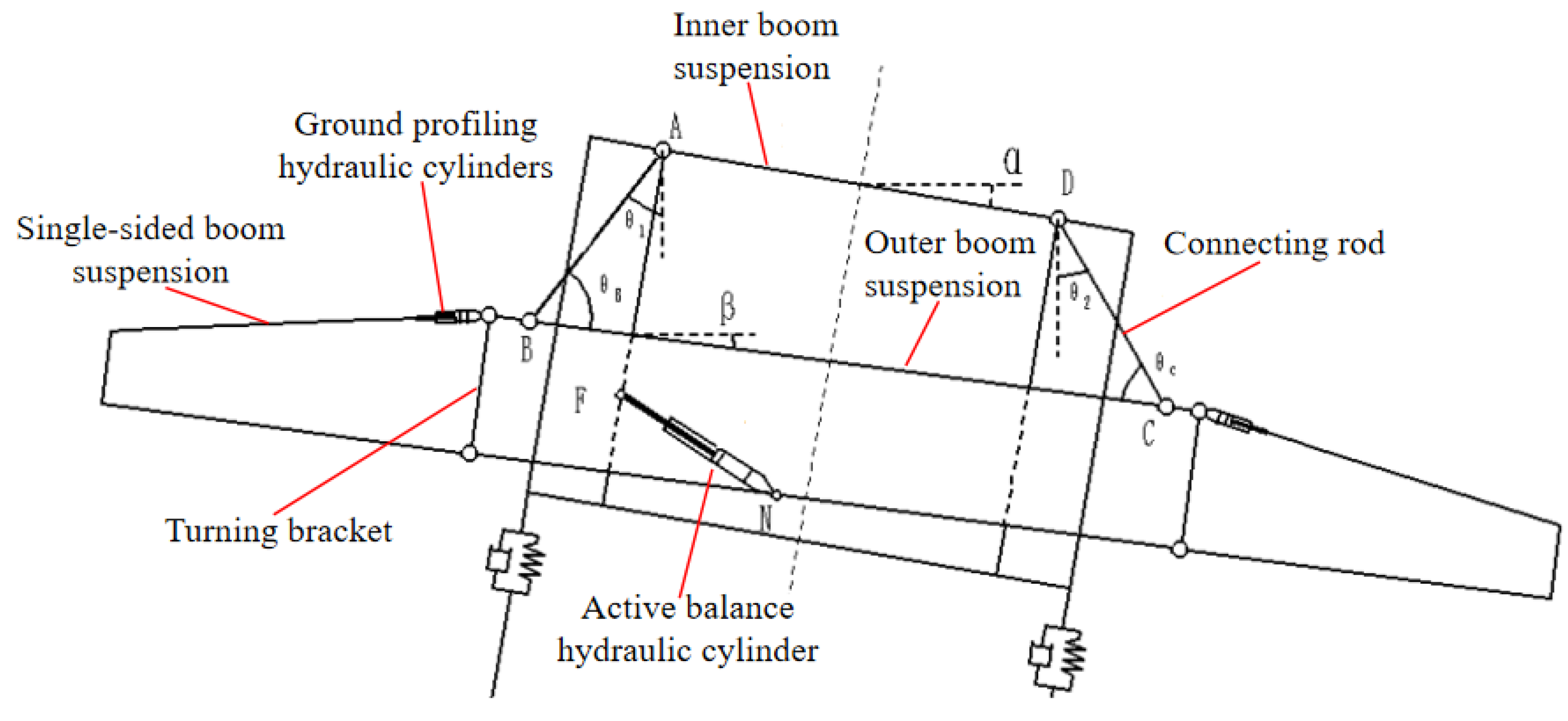
Figure 1. Schematic diagram of the working principle of the boom suspension.
Agriculture 14 00319 g001
Figure 2. Force analysis diagram of boom suspension.
Agriculture 14 00319 g002
Figure 3. A 3D model of the two-link trapezoidal boom suspension. (a) Middle boom suspension; (b) single-sided boom suspension.
Agriculture 14 00319 g003
Figure 4. The virtual prototype of boom suspension based on ADAMS.
Agriculture 14 00319 g004
Figure 5. Construction and geometrical dimensions of specimens.
Agriculture 14 00319 g005
Figure 6. The dynamic characteristics test of 3WPYZ high gap self-propelled sprayer boom suspension.
Agriculture 14 00319 g006
Figure 7. Time domain response diagram of boom suspension. (a) The excitation amplitude is 5°; (b) the excitation amplitude is 25°.
Agriculture 14 00319 g007
Figure 8. Dynamic characteristic diagram of boom suspension under different excitation frequencies. (a) ω = 0.1 rad/s; (b) ω = 0.5 rad/s; (c) ω = 5 rad/s; and (d) ω = 10 rad/s.
Agriculture 14 00319 g008
Figure 9. The relationship curve between the maximum swing angle of the external spray boom suspension and the frequency under the change in LAD.
Agriculture 14 00319 g009
Figure 10. Relationship between boom suspension swing angle and LAD. (a) The swing angle at w = 10 rad/s; (b) relation at natural frequencies.
Agriculture 14 00319 g010
Figure 11. Relationship between boom suspension swing angle and LBC. (a) The swing angle at w = 10 rad/s; (b) relation at natural frequencies.
Agriculture 14 00319 g011
Figure 12. Relationship between boom suspension swing angle and LAB. (a) The swing angle at w = 10 rad/s; (b) relation at natural frequencies.
Agriculture 14 00319 g012
Figure 13. Relationship between boom suspension swing angle and d. (a) The swing angle at w = 10 rad/s; (b) relation at natural frequencies.
Agriculture 14 00319 g013
Figure 14. Diagram of the maximum swing angle and frequency relationship between the before and after of the boom suspension improvement. (a) Before improvement; (b) after improvement.
Agriculture 14 00319 g014
Figure 15. Displacement and stress cloud diagram boom suspension. (a) Displacement cloud of single-side boom; (b) stress cloud of single-side boom; (c) displacement cloud of single-side boom; and (d) stress cloud diagram of external boom.
Agriculture 14 00319 g015
Figure 16. The first six non-rigid modes of the boom suspension. (a) First mode shape; (b) second mode shape; (c) third mode shape; (d) fourth mode shape; (e) fifth mode shape; and (f) sixth mode shape.
Agriculture 14 00319 g016
Figure 17. Boom suspension swing test results. (a) Height is 500 mm; (b) height is 1200 mm; and (c) height is 2500 mm.
Agriculture 14 00319 g017
Table 1. Main structural parameters of the two-link trapezoidal boom suspension.
ParametersValuesUnits
LAB270mm
LBC1180mm
LCD270mm
LAD860mm
LG314mm
θ ¯ 0.63rad
IB9.89 × 109kg·mm2
MB530.87kg
d4mm
Table 2. The section shape and wall thickness of each component of the boom suspension.
Main ComponentsSection ShapeSection Shape Size (mm)Wall Thickness (mm)
Inner boom suspensionAgriculture 14 00319 i00160 × 405
Outer boom suspensionAgriculture 14 00319 i00260 × 405
Turning bracketsAgriculture 14 00319 i003100 × 804
First stage of boom suspensionAgriculture 14 00319 i00460 × 403
Second stage of boom suspensionAgriculture 14 00319 i00560 × 402
End stage of boom suspensionAgriculture 14 00319 i00620 × 202
Table 3. Level coding table of boom suspension test factors.
LevelFactor
LAB (mm)LBC (mm)LAD (mm)d (mm)
122010508403
223511008803.5
325011509204
426512009604.5
5280125010005
Table 4. Orthogonal test scheme and test results.
LevelLAB (mm)LBC (mm)LAD (mm)d (mm)EFSwing Angle (deg)Natural Frequency (rad/s)
122010508403111.70691.29
222011008803.5221.218351.3571
322011509204330.88751.449
422012009604.5440.713151.5061
5220125010005550.64191.5143
623510508804451.21481.6265
723511009204.5510.97821.698
823511509605120.86231.7082
9235120010003232.30011.502
1023512508403.5340.62691.1204
1125010509205241.34232.2286
1225011009603353.0311.7449
13250115010003.5412.30381.8163
1425012008404520.52261.1816
1525012508804.5130.41651.2245
1626510509603.5533.37512.1878
17265110010004142.67972.2795
1826511508404.5250.502751.2939
1926512008805310.461551.3147
2026512509203420.65021.7041
21280105010004.5323.8272.713
2228011008405430.56541.4163
2328011508803541.68281.519
2428012009203.5151.5111.498
2528012509604210.91011.4265
Table 5. Swing angle variance analysis result.
CategorySum of SquaresDegree of FreedomMean SquareFp
Model10.50160.6618.380.0001 **
A-LAB0.3540.0872.450.1307
B-LBC3.9740.9927.81<0.0001 **
C-LAD3.5940.9025.180.0001 **
d2.5840.6518.070.0005 **
error0.2980.036
sum10.7824
R-squared0.9735
Note: ** indicates that the impact is extremely significant (p < 0.01).
Table 6. Natural frequency variance analysis result.
CategorySum of SquaresDegree of FreedomMean SquareFp
Model10.50160.6618.380.0001 **
A-LAB0.3540.0872.450.1307
B-LBC3.9740.9927.81<0.0001 **
C-LAD3.5940.9025.180.0001 **
d2.5840.6518.070.0005 **
error0.2980.036
sum10.7824
R-squared0.9735
Note: ** indicates that the impact is extremely significant (p < 0.01).
Table 7. Data filtering range value.
NameGoalLimitLimitWeightWeightImportance
A-LABIn range220280113
B-LBCIn range10501250113
C-LADIn range8401000113
dIn range35113
Swing Angle Minimize0.13.827113
Natural Frequency In range0.71.3113
Table 8. Orthogonal test simulation result value after screening.
GroupLABLBCLADdE *F *Swing Angle Natural Frequency Rationality
126512508404110.3509711.179910.933
223512508404110.3565991.046620.931
325012508404110.380371.100830.925
422012508804110.3975611.095590.920
523512508805110.4445821.167170.908
628012508405110.455191.145580.905
725012508805110.4742181.227620.900
826512008405110.5026941.189740.892
923512008404.5110.5107551.055350.890
1025012008404.5110.5448021.110.881
1122011508404.5110.5483781.098730.880
1228012508804.5110.5674991.277520.875
1322012008803.5110.5694261.104720.874
1423511508403.5110.6132371.170520.862
1523512008803.5110.6367731.17690.856
1628012008403.5110.6519671.155130.852
1725011508403110.6541151.231140.851
1825012008803110.679221.237850.845
Note: * indicates that the impact is significant.
Table 9. Inner boom suspension and single-side boom suspension swing angle value.
StructureSuspension Height (mm)Counterclockwise Maximum Swing Angle (deg)Clockwise Maximum Swing Angle (deg)
Inner boom suspension5003.223.92
12003.223.92
25003.223.98
Single-sided boom suspension5000.6490.827
12000.8181.01
25000.6620.776
Disclaimer/Publisher’s Note: The statements, opinions and data contained in all publications are solely those of the individual author(s) and contributor(s) and not of MDPI and/or the editor(s). MDPI and/or the editor(s) disclaim responsibility for any injury to people or property resulting from any ideas, methods, instructions or products referred to in the content.