Abstract
To improve the distribution of mud particles collected in the tray during the operation of paddy field mud spreader blades, the optimal combination of parameters for the blades that results in the best uniformity of mud dispersion needs to be identified. In this study, a thorough force analysis was conducted on the spreading process, and computational equations were formulated to describe the motion of mud particles. By utilizing the discrete element simulation technique, a simulation model was developed to accurately represent the intricate interaction between the blades and mud particles. Through the single-factor simulation experiments, the ranges of key parameters such as the rotation radius, bending angle, sub-blade tilt angle, forward velocity, and rotational speed of the blade were determined. A secondary orthogonal rotational combination design was employed to establish a regression prediction model between the non-uniformity of mud dispersion and the key blade parameters. Subsequently, a multivariate single-objective optimization method was used to develop an optimization model for the non-uniformity of mud dispersion. The results indicate that the hierarchical order of factors influencing the non-uniformity of mud dispersion is as follows: rotation radius > rotation speed > bending angle > forward velocity > sub-blade tilt angle. To achieve a minimum spreading non-uniformity of 29.63%, a specific configuration is required, which includes a blade rotation radius of 188 mm, a bending angle of 121°, a sub-blade tilt angle of 30°, a forward velocity of 400 mm/s, and a rotation speed of 191 r/min. Finally, the accuracy of the optimization results was verified by means of bench tests. The research results provide a crucial reference for enhancing the uniformity of mud dispersion in paddy field mud spreader blades.
1. Introduction
Mechanized rice cultivation with machine-transplanted seedlings ensures high yield, efficiency, and reduced labor intensity, resulting in significant labor savings [1,2]. The standardization of seedlings is crucial for mechanized transplanting, making seedling breeding a critical initial phase in rice cultivation [3,4]. In Asian regions, the prevalent method involves field-level soft trays for seedling breeding and transplantation, encompassing steps such as compartmentalization, laying seedling trays, mud filling, sowing on mud, pressing, and furrowing. Notably, manual mud filling in trays stands out as the most labor-intensive step, leading to high labor intensity and low efficiency. The adoption of a mud spreader facilitates the rapid dispersion of watery mud from paddy fields onto both sides of seedling trays, significantly improving mud filling efficiency while reducing labor intensity. However, existing design flaws in mud spreader blades compromise the uniformity of post-operation mud spreading in the collection tray, falling short of agronomic standards for the rice cultivation seedling phase. Uneven thicknesses of mud in seedling trays hinder the effective and uniform supply of essential resources like water and nutrients necessary for optimal growth, adversely affecting seedling quality, growth rate during the transplanting process, along with survival rates afterward. Consequently, optimizing the design of mud spreader blades can improve the uniformity of the machine’s operation, help to enhance the mechanization level of the seedling raising process in the field, and promote the development of high-end mud spreader machines in order to achieve high energy efficiency, high reliability, and high added value. At the same time, it has important practical significance for promoting the development of the high-end mud spreader equipment industry and promoting the process of agricultural modernization.
Blades are the direct components that perform operational functions in various agricultural machines, such as plows, trenchers, agitators, mud spreaders, ridgers, weeders, and field management tools, playing a pivotal role in determining the operational performance of these implements [5,6,7,8,9,10,11]. Scholars have extensively researched the operational performance of blades used in agricultural machinery in soil environments. Some researchers have explored altering particle trajectories by designing blades of different shapes to influence the movement of soil particles along predetermined paths [12,13,14,15]. Others have investigated the cutting and scattering processes of blades to uncover underlying patterns of particle motion [16,17,18,19,20]. Additionally, computer simulation techniques have been employed by some scholars to establish numerical models simulating blade operation processes [21,22,23,24,25,26,27]. However, it should be noted that mud spreader blades possess structural characteristics that differ from commonly used agricultural machinery blades; thus, their operational characteristics when interacting with mud exhibit distinctions from ordinary blades. Consequently, a series of studies on technical aspects and methods for utilizing paddy field machinery have been conducted by researchers [28,29,30,31,32,33,34,35,36,37]. Zhang, Y. et al. [38] optimized the operational parameters of a weeder blade used in rice fields, and their results demonstrated that the optimized blade achieved satisfactory performance according to agronomic requirements. Zhu, D. et al. [39] employed finite element and discrete element methods to develop a dynamic model for the coupled system of blade–straw–rice soil, with a focus on analyzing the operational processes of blades in paddy fields. The model was validated through experimental investigations conducted in soil grooves. Ding, Q. et al. [40] employed reverse engineering techniques to acquire crucial geometric parameters for agitator blades, while proposing specialized design parameters and investigating design methodologies through field experiments. Matin, MA. et al. [41] focused on the design and simulation analysis of blades for producing high-quality seedbeds in paddy field furrows, with a focus on enhancing agricultural productivity through improved soil preparation techniques. Torotwa, I. et al. [42] investigated the adaptability and performance of bionic rotary tiller blades utilized in paddy fields, revealing that these biomimetic blades exhibited reduced power requirements while achieving finer and more uniform particle sizes. Pang, C. et al. [43] designed a device that can achieve the continuous paving of rice seedling trays without silt blocking or interruption during the process of slurry delivery. Zhang, X. et al. [44] designed a combined blade roller that can be used in paddy fields, and the operation quality is better than that of spiral blade rollers and traditional rotary cultivators. Xie, Y. et al. [45] investigated the efficacy and power consumption of various blade configurations during homogenization in paddy fields and optimized the parameter set for optimal slurry homogenization. Their objective was to optimize seed germination and early seedling vitality by meticulously designing the blades and conducting simulation analysis. However, currently, there is a lack of computational models specifically designed to assess the uniformity in spreading after the operation of mud spreader blades, impeding the precise simulation and prediction of how mud particles are uniformly scattered in the collection tray under the influence of these blades. Therefore, this study aims to investigate the uniformity of mud particle dispersion in the collection tray following paddy field mud spreader blade operation, with the objective of establishing a robust theoretical foundation for enhancing mud spreading efficiency.
2. Materials and Methods
2.1. Operational Principle of Mud Spreader
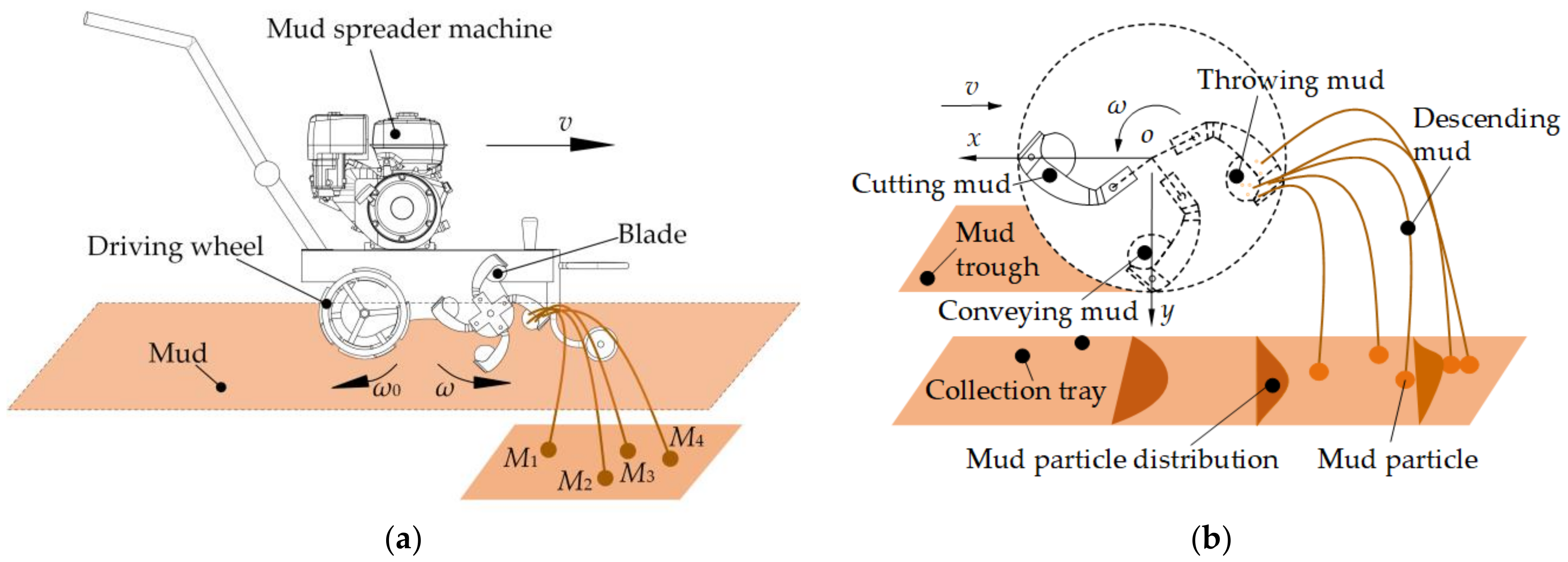
The operational procedure of the mud spreader blades for dispersing mud particles is depicted in Figure 1a. The driving wheel of the machine propels the blade to move uniformly along a linear trajectory, while simultaneously enabling rotational movement around the central shaft. The blades initiate mud cutting as they rotate from above the mud pool toward the mud trough area during the first half of each cycle. Continuing rotation assists in conveying mud as it reaches the bottom during the second half. As this process nears completion, blade action effectively disperses and directs descending mud particles into seedling collection trays positioned on both sides of the furrow, thereby concluding the operation of spreading mud, as shown in Figure 1b.
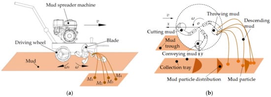
Figure 1.
Operational procedure of the mud spreader blades. (a) Overall working principle; (b) the process of splashing using a single blade.
2.2. Mechanics Model of Mud Particle Motion
2.2.1. Force Analysis on Particles
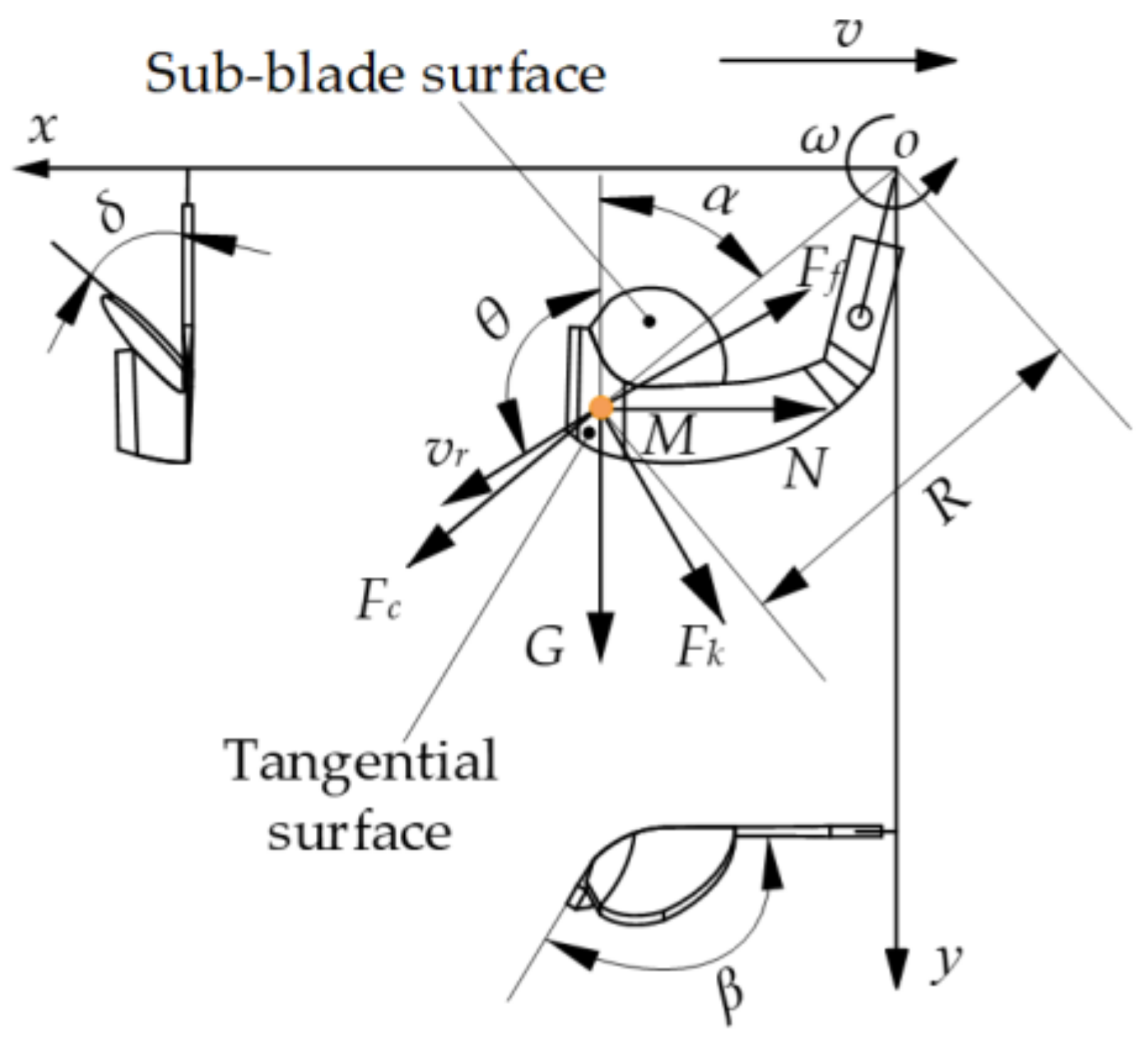
Considering particle M located on the tangential surface as the focal point of investigation, it encounters various forces, including gravity (G), normal force (N), centrifugal force (Fc), viscous frictional resistance (Ff), and Coriolis inertial force (Fk) while moving along the blade surface, as illustrated in Figure 2.
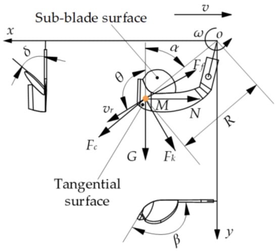
Figure 2.
Force diagram of mud particles.
The gravitational force vector G points vertically downwards, and its projection in the coordinate system is as follows:
The normal force N is oriented perpendicular to the positive section of the blade, with its projection size in the coordinate system being:
The centrifugal force Fc acts outward along the radial direction of the blade, and its magnitude projected onto the coordinate system is as follows:
The resistance of viscous friction force Ff opposes the direction of particle movement, and its magnitude projected onto the coordinate system is as follows:
The Coriolis inertia force Fk is oriented parallel to the axis of rotation and perpendicular to the direction of motion, with its magnitude projected in the coordinate system as follows:
where ω is the rotation speed of the blade; θ represents the angle between the velocity of mud particles in the xoy coordinate system and the y-axis; β denotes the bending angle of the blade; μ stands for the friction coefficient between mud particles and blades; m represents the weight of a mud particle; g is the acceleration due to gravity; α indicates the position angle of a mud particle in polar coordinate system; R refers to the distance from center of rotation to mud particles; N represents the normal force exerted on mud particles; and Fn signifies viscous force acting on mud particles.
2.2.2. Differential Equation of Particle Motion
According to Newton’s second law, the equation of motion for mud particle M along the blade surface can be derived as follows:
By substituting Equations (1)–(5) into Equation (6), the following formula can be derived.
According to the actual dynamics of particle motion, the initial boundary conditions are established. At t = 0, the precise position of mud particles is as follows:
where α is the initial position of the blade at t = 0.
Assuming an initial velocity of 0 for the mud particles, the following equation can be obtained:
By applying Equations (8) and (9) of the initial boundary conditions to Equation (7), the position (S) and velocity (V) of the mud particle at the instant of ejection (t0) in the coordinate system can be determined.
2.2.3. Trajectory Equation of Particle Motion
Assuming minimal interparticle forces and negligible air resistance among mud particles, and considering that the particles are solely influenced by gravity upon departing from the blade, the mud particles expelled by the blade will follow a parabolic trajectory with a specific velocity, magnitude, and direction at the moment of departure. The displacement equations along the x, y, and z axes for the particle after leaving the blade are provided by Equation (10).
where the variables vx, vy, and vz represent the component velocities of the particle in the x, y, and z directions at the moment of ejection (t0), while Sx, Sy, and Sz signify the position of the particle at the moment of ejection (t0).
It can be inferred from Equation (10) that the motion trajectory of mud particles on the tangent surface of the blade is influenced by factors such as the turning radius R, bending angle β, forward velocity v, and rotation speed of the blade w. Employing a similar methodology, the trajectory of mud particles positioned on the sub-blade surface post ejection can be computed. Upon analysis, crucial parameters influencing the trajectory of mud particles on the sub-blade surface include the rotational radius of the blade R, the tilt angle of the sub-blade δ, the forward velocity v, and the rotation speed w. Since particle movement directly affects spreading uniformity, key factors impacting particle distribution during mud spreader blade operation encompass initial velocity, initial position, and ejection angle at departure. The specific critical parameters involve rotational radius R, bending angle β, sub-blade tilt angle δ, forward velocity v, and rotation speed w. This finding lays a theoretical foundation for the subsequent simulation and experimental research.
2.3. Simulation Model
2.3.1. Discrete Element Model
EDEM is a piece of high-performance software for simulating bulk and granular materials which can quickly and accurately simulate and analyze the behavior of coal, soil, fiber, grain, tablets, powder, etc. In this study, in order to accurately simulate the actual operating state of mud spreading in the field, a virtual mud tank with a size of 3000 × 400 × 400 mm was established using the EDEM software (EDEM2020) to simulate the interaction between a mud spreader blade and mud particles, considering both the blade’s spreading mode and boundary conditions required for processing. The virtual trough functioned as a particle generator, producing two types of particles: soil and water particles. Each individual sphere had a standardized radius of 5 mm, resulting in a total of 1,020,000 spheres to ensure an ample supply of particles for comprehensive simulation within the mud trough. The blades were meticulously designed using three-dimensional software (Solidworks 2018) and subsequently imported into the EDEM software. In EDEM, an interaction model between the blades and mud particles was established, as depicted in Figure 3. The Johnson–Kendall–Roberts (JKR) contact model is an extension of the well-known Hertz contact model proposed by Johnson in 1971 [46]. The model considers the gravitational force caused by van der Waals effect and uses surface energy to represent the bonding force between particles. It is particularly suitable for simulating wet materials with adhesive and agglomerative properties, such as ores, mud, etc. Therefore, the JKR contact model with a surface energy set to 0.075 J/m2 was employed to simulate interactions among mud particles, water particles, and their boundaries. To maintain the continuous movement of mud particles throughout the simulation process, a fixed time step of 2 × 10⁻⁴ s was adopted with a total simulation time of 5 s. Additionally, the mesh unit size was set at twice the particle radius (10 mm) to facilitate precise data processing in subsequent analyses.
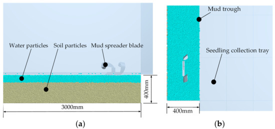
Figure 3.
EDEM model. (a) Front view; (b) top view.
2.3.2. Single-Factor Experiment
Using the blade’s rotational radius R (X1), bending angle β (X2), sub-blade tilt angle δ (X3), forward velocity v (X4), and rotation speed w (X5) as experimental factors, and employing the non-uniformity index Y as the experimental index, the influence of each factor on the non-uniformity in the spreading index was investigated individually. Considering practical production and paddy field seedling mud cultivation requirements, the initial gradient levels for each factor were set as follows: blade rotational radius at 150, 160, 170, 180, and 190 mm; bending angle at 105, 120, 135, 150, and 165°; sub-blade tilt angle at 5, 25, 45, 65, and 85°; forward velocity values of 150, 300, 450, 600, and 750 mm/s; and rotation speed values of 120, 180, 240, 300, and 360 r/min. During the single-factor experiments, all factors except for their own horizontal variation were maintained at their mid-levels. Each experiment was repeated three times, and an average value was taken as the final result.
2.3.3. Secondary Orthogonal Rotational Combination Design Experiment
Based on the results of the single-factor experiment, a secondary orthogonal rotational combination design experiment with five factors and five levels was used to optimize parameters such as rotating radius (X1), bending angle (X2), sub-blade tilt angle (X3), forward velocity (X4), and rotation speed (X5) in order to achieve uniformity in spreading. In total, 36 experiments were conducted, including 10 replications for the zero-level experiment. The factors and levels of the experiment are shown in Table 1.

Table 1.
Experimental factors and codes.
2.3.4. Calculation Method of Experimental Index
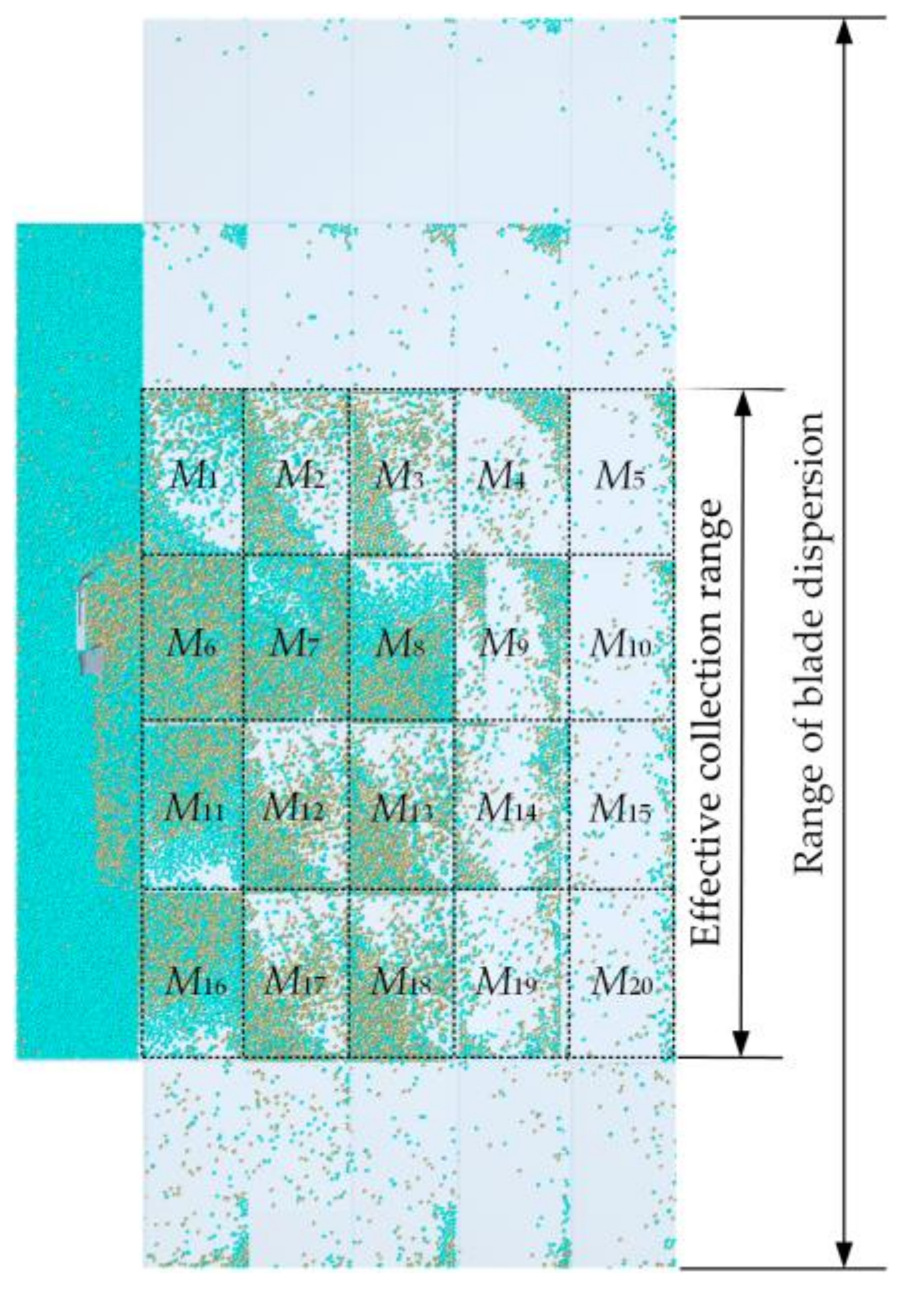
To assess the even distribution of mud particles in the collection tray following the operation of the mud spreader blades, the non-uniformity index Y was employed to depict the particle distribution in the tray. A smaller non-uniformity index Y indicates a higher level of uniformity [47]. To calculate the uniformity of mud particles in the collection tray, it was divided into 20 groups of individual grids, as depicted in Figure 4. Following each experiment, the mud particles scattered on the collection tray were counted based on the grid selection criteria. Grids with a particle count below 500 were considered ineffective and excluded from statistical analysis. After excluding ineffective grids, the number and weight of mud particles in each grid were tallied, and Equation (11) was used to calculate the value of the non-uniformity index Y.
where Mi denotes the mass of mud in each mesh; signifies the average volume of mud; and Y indicates the non-uniformity of dispersion.

Figure 4.
Cell division of the collection tray.
3. Results and Discussion
3.1. Single-Factor Experiment Results and Discussion
3.1.1. Influence of Rotating Radius on Non-Uniformity in Spreading
With the bending angle set at 135°, sub-blade tilt angle set at 45°, forward velocity set at 450 mm/s, and rotation speed set at 240 r/min, the impact of varying rotational radius on non-uniformity in spreading was obtained, as depicted in Figure 5.
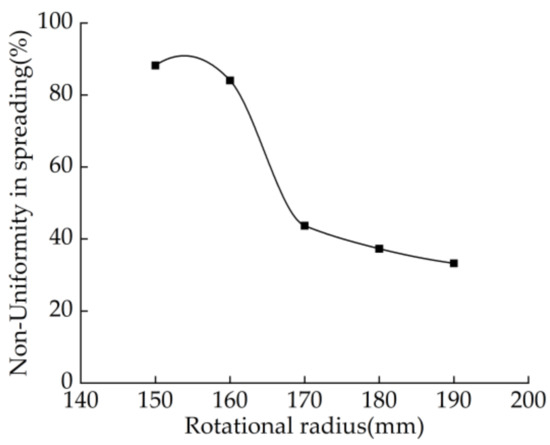
Figure 5.
Curve of influence on turning radius.
As shown in Figure 5, an increase in the blade rotational radius leads to a gradual reduction in the non-uniformity of mud spreading, indicating an improvement in the uniformity of mud spreading. For a rotational radius within the range of 170–190 mm, the non-uniformity is relatively small and decreases slowly, suggesting an optimal effect on mud spreading within this range. For a rotational radius in the range of 150–160 mm, the non-uniformity is poorer due to inadequate stirring and spreading of mud particles when the blade’s rotational radius is small, which affects the uniformity of mud spreading. Therefore, it can be concluded that the optimal blade rotational radius for efficient mud spreader operations falls between 170 and 190 mm.
3.1.2. Influence of Bending Angle on Non-Uniformity in Spreading
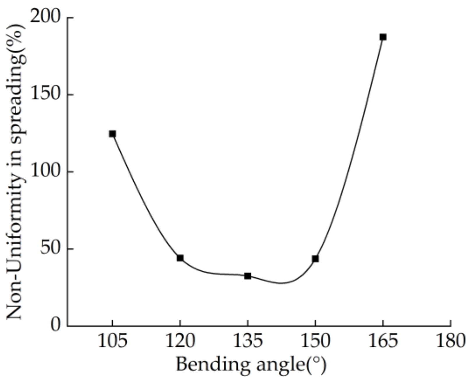
With a fixed rotational radius of 170 mm, a sub-blade tilt angle of 45°, a forward velocity of 450 mm/s, and a rotation speed of 240 r/min, the impact of varying bending angles on non-uniformity in spreading was obtained, as shown in Figure 6

Figure 6.
Curve of influence on bending angle.
The results depicted in Figure 6 demonstrate that the non-uniformity in spreading initially decreases and subsequently increases as the blade bending angle increases. Within the range of bending angles from 120° to 150°, a relatively small and stable non-uniformity in spreading is observed, indicating a high level of uniformity. However, when the bending angle is either 105° or 165°, there is a significant increase in non-uniformity during spreading. This can be primarily attributed to an excessively small bending angle resulting in a relatively straight blade orientation, which hinders the effective dispersion and scattering of mud particles. Conversely, an excessively large bending angle creates substantial resistance for mud particles during the scattering process, leading to an increased non-uniformity in spreading. Therefore, it is recommended that for optimal mud spreading efficiency, the preferred blade bending angle falls within the range of 120° to 160°.
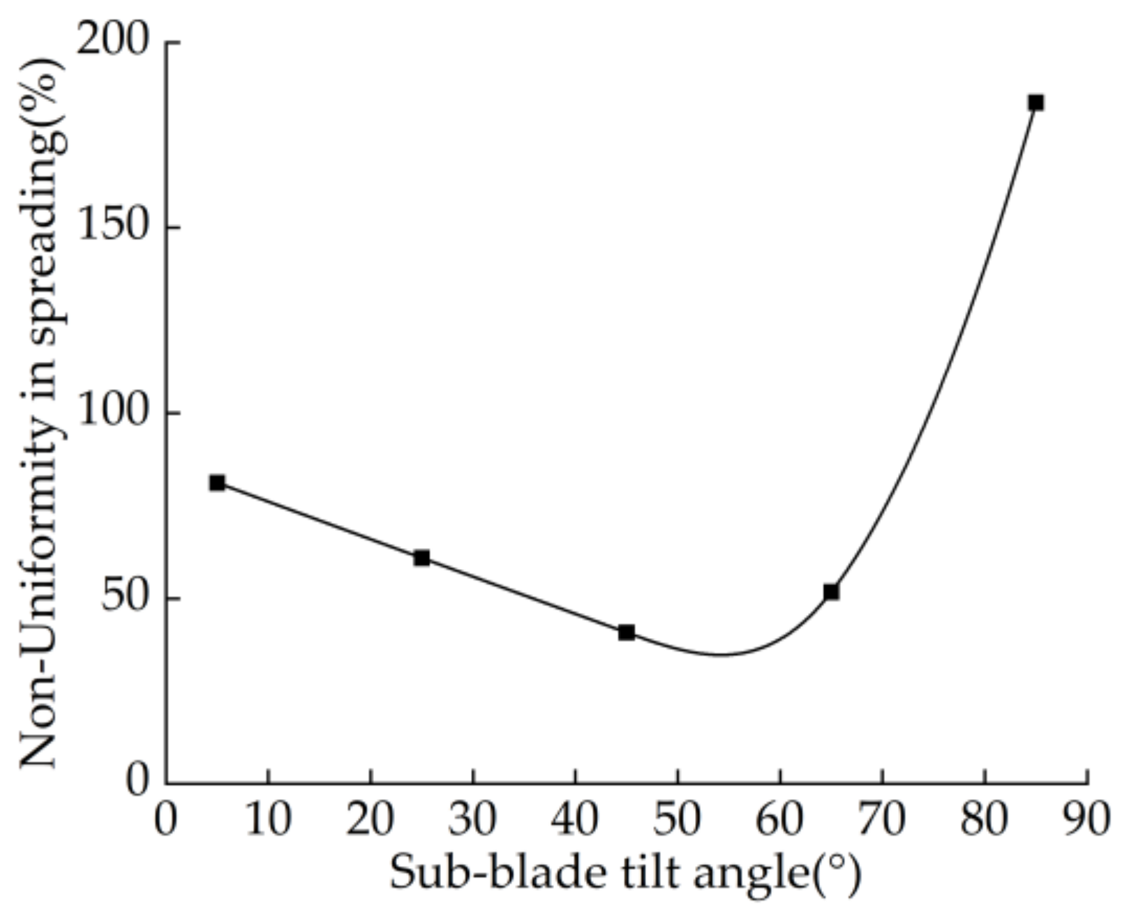
3.1.3. Influence of Sub-Blade Tilt Angle on Non-Uniformity in Spreading
With a fixed rotational radius of 170 mm, bending angle of 135°, forward velocity of 450 mm/s, and rotation speed of 240 r/min, the impact of varying sub-blade tilt angles on non-uniformity in spreading was obtained, as illustrated in Figure 7.
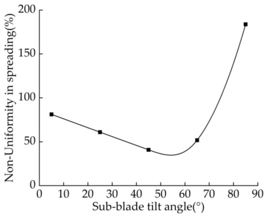
Figure 7.
Curve of influence on sub-blade tilt angle.
As illustrated in Figure 7, the non-uniformity in spreading initially decreases and then sharply increases with an increase in the sub-blade tilt angle. Within the range of 5–65° for the sub-blade tilt angle, a gradual decrease in non-uniformity indicates optimal mud spreading. However, at a sub-blade tilt angle of 85°, there is a sharp increase in non-uniformity due to the concentration of mud particles in specific areas rather than uniform spreading. Therefore, the preferred sub-blade tilt angle for efficient mud spreading is considered to be within the range of 5–65°.
3.1.4. Impact of Forward Velocity on Non-Uniformity in Spreading
With a fixed rotating radius of 170 mm, a bending angle of 135°, a sub-blade tilt angle of 45°, and a rotation speed of 240 r/min, an examination was conducted to assess the impact of varying forward velocities on non-uniformity in spreading, as depicted in Figure 8.
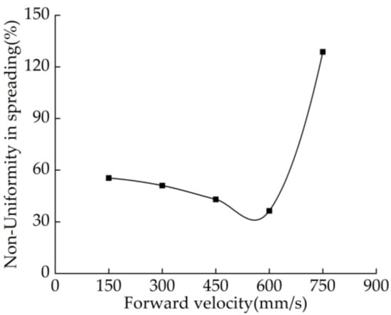
Figure 8.
Curve of influence on forward velocity.
As indicated in Figure 8, the non-uniformity in spreading initially decreases and then sharply increases with an increase in the blade’s forward velocity. Within the range of forward velocity from 150 to 600 mm/s, there is a gradual decrease in non-uniformity, indicating optimal mud spreading within this range. However, at a forward velocity of 750 mm/s, there is a sharp increase in non-uniformity. This can be mainly attributed to the excessively high forward velocity, which subjects mud particles to significant impact forces and resistance during the scattering process, resulting in splashing and jumping phenomena that exacerbate the non-uniformity in spreading. Therefore, in order to achieve better mud spreading performance, it is recommended to maintain a preferred blade forward velocity between 150 and 650 mm/s.
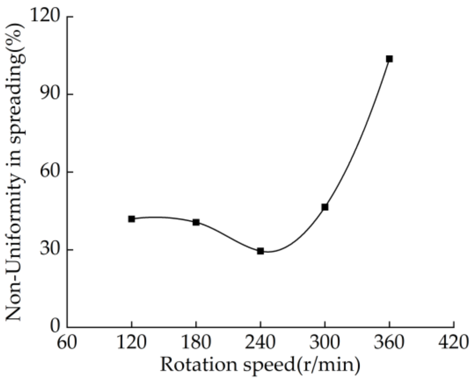
3.1.5. Influence of Rotation Speed on Non-Uniformity in Spreading
With a rotating radius fixed at 170 mm, a bending angle of 135°, a sub-blade tilt angle of 45°, and a forward velocity of 450 mm/s, an examination was conducted to evaluate the impact of varying rotation speeds on spreading non-uniformity, as illustrated in Figure 9.

Figure 9.
Curve of influence on rotation speed.
As depicted in Figure 9, the non-uniformity in spreading initially remains stable before significantly increasing with an increase in blade rotation speed. Within the range of rotation speeds from 120 to 300 r/min, relatively little non-uniformity in spreading is observed. However, at a rotation speed of 360 r/min, the non-uniformity in spreading markedly increases. This can be attributed to the excessively high rotation speed causing mud particles to exceed the effective range of the blade without sufficient spreading. Therefore, it is considered that the optimal blade rotation speed for mud spreading falls between 120 and 320 r/min.
3.2. Results and Analysis of the Secondary Orthogonal Rotational Combination Design Experiment
3.2.1. Experimental Results
The single-factor experiment analyzed the influence of rotation radius, bending angle, sub-blade tilt angle, forward velocity, and rotational speed on the non-uniformity of mud spreading, and the range of factor values was determined. In order to analyze the influence of multiple factors on the non-uniformity of mud spreading, a secondary orthogonal rotational combination design experiment was conducted with the rotation radius, bending angle, sub-blade tilt angle, forward velocity, and rotational speed as experimental factors and the non-uniformity of mud spreading as the experimental index. The experimental details and results are shown in Table 2.
Table 2.
Result data of the experiment.
3.2.2. Regression Prediction Model
According to the experimental results in Table 2, a regression prediction model was established between the non-uniformity in spreading (Y) and the rotating radius (X1), bending angle (X2), sub-blade tilt angle (X3), forward velocity (X4), and rotation speed (X5) by using Design Expert 13.0 software, as shown in Equation (13). The analysis and fitting of experimental data resulted in the variance analysis of non-uniformity in spreading (Y), as detailed in Table 3.
Table 3.
Variance analysis of non-uniformity in mud spreading.
As can be seen from Table 3, the F-value for the second-order regression model is 53.1, with a significance level of p < 0.0001. The lack-of-fit test F-value is 0.007, with a p-value of 1.00 > 0.05, indicating that the model fits to the data well. All first-order terms (X1, X2, and X4), second-order terms (X12, X32, and X52), and interaction terms (X1X2, X1X3, X1X4, X1X5, X2X3, X2X4, X2X5, and X4X5) have p-values less than 0.05, suggesting the significant impact on non-uniformity in spreading. The coefficient of determination (R2) for the model is calculated to be 0.9861, demonstrating its ability to explain approximately 98% of the variability observed in the original data and indicating reliable predictive capability. After excluding non-significant factors, the optimized regression prediction model can be expressed as follows:
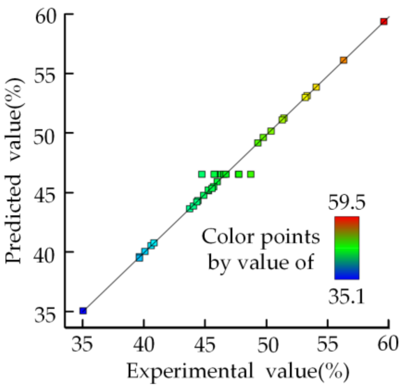
To further confirm the reliability of the non-uniformity in spreading regression model, the acquired regression equation was employed to calculate predicted values, which were subsequently compared with the experimental values, as shown in Figure 10. It is clear that data points are clustered around the fitted line, affirming the high degree of fitting of the regression model and showcasing its accuracy. Consequently, the regression prediction model for dispersion uniformity is deemed significant, with high fitting and reliable predictive capability.
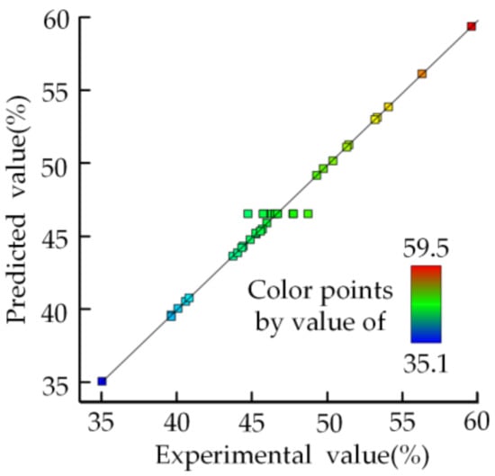
Figure 10.
Comparison between the predicted values and the experimental results.
3.2.3. Analysis of the Impact Intensity of Factors
The significant testing analysis from Table 3 reveals that certain individual factors, namely X1, X2, X4, X12, X32, and X52, exert a noteworthy influence on the non-uniformity in spreading (p < 0.05). The impact of each specific factor on the model can be quantified by its contribution rate (K value), which directly corresponds to the degree of influence. The calculation method outlined in Equations (15) and (16) is employed to determine the magnitude of the contribution rate.
where F represents the F-value of each regression term in the regression equation; θ is the assessment value of the regression term on the F-value; and KXj denotes the contribution rate of each influencing factor.
The contribution rates for the blade rotation radius (X1), bending angle (X2), sub-blade tilt angle (X3), forward velocity (X4), and rotation speed (X5) to the non-uniformity in spreading, as calculated based on Equation (16), are determined to be 5.99, 5.92, 5.69, 5.78, and 5.98, respectively. Therefore, the order of contribution rates for each factor to uneven spreading is as follows: blade rotation radius (X1) > rotation speed (X5) > bending angle (X2) > forward velocity (X4) > sub-blade tilt angle (X3).
3.2.4. Analysis of the Impact Effects of Interaction Factors on Non-Uniformity in Spreading
As indicated in Table 3, the interaction factors significantly affecting non-uniformity in spreading (Y) are primarily X1X2, X1X3, X1X4, X1X5, X2X3, X2X4, X2X5, X3X4, X3X5, and X4X5 (p < 0.05). By utilizing Design-Expert 13.0 software for data processing, the response surface of the significant factors’ interaction effects on non-uniformity in spreading was obtained and is illustrated in Figure 11.
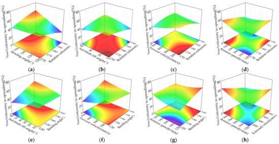
Figure 11.
Response surface of mud non-uniformity in spreading. (a) Rotation radius and bending angle; (b) rotation radius and sub-blade tilt angle; (c) rotation radius and forward velocity; (d) rotation radius and rotation speed; (e) bending angle and sub-blade tilt angle; (f) bending angle and forward velocity; (g) bending angle and rotation speed; and (h) forward velocity and rotation speed.
From Figure 11a, it is evident that when the rotation radius of the blade is relatively small, such as within the range of 170–175 mm, there is a gradual decrease in non-uniformity in spreading with an increase in bending angle. This implies that at smaller rotation radii, an increased bending angle facilitates the more uniform dispersion of mud particles. Conversely, when the rotation radius of the blade is larger, for instance, within the range of 175–190 mm, there is a significant increase in non-uniformity in spreading with an increase in bending angle. This can be attributed to the larger rotation radius providing greater kinetic energy and resulting in a wider range of spreading when ejecting mud particles. Moreover, for blade bending angles between 120 and 140°, there exists a negative correlation between non-uniformity in spreading and the rotation radius, whereas for bending angles between 140 and 160°, there exists a positive correlation between non-uniformity in spreading and the rotation radius. When the rotation radius is 190 mm and the bending angle is set at 120°, it reaches its minimum value of non-uniformity at 26.11%.
According to Figure 11b, the non-uniformity in spreading decreases with an increase in the sub-blade tilt angle when the blade’s rotation radius falls within the range of 170–180 mm. For smaller rotation radii, increasing the sub-blade tilt angle enhances the cutting effect on mud, resulting in a more uniform spread of mud particles. However, as the rotation radius varies within the range of 180–190 mm, this trend reverses due to the increased force exerted on mud particles when passing through the sub-blade at a larger tilt angle, leading to more dispersed particle ejection. Furthermore, non-uniformity in spreading is negatively correlated with the rotation radius for sub-blade tilt angles between 5 and 30° and positively correlated with rotation radius for sub-blade tilt angles ranging from 30 to 65°. At a rotation radius of 190 mm and a sub-blade tilt angle of 5°, non-uniformity in spreading reaches its minimum value of 34.09%.
As depicted in Figure 11c, when the rotation radius of the blade falls within the range of 170–180 mm, there is a gradual reduction in spreading non-uniformity with an increase in forward velocity. This phenomenon can be attributed to the smaller rotation radius, which facilitates the easier ejection of mud particles after being subjected to sub-blade force. Simultaneously, as forward velocity increases, the force acting on mud particles also intensifies correspondingly, leading to a more concentrated flow of ejected mud particles and consequently reducing non-uniformity in spreading. However, when the rotation radius of the blade lies within the range of 180–190 mm, this trend is reversed due primarily to the larger rotation radius and higher forward velocity exacerbating disturbances in mud particle flow. Consequently, it becomes challenging for mud particles to maintain a stable ejection state. In addition, for blade forward velocities ranging from 150–450 mm/s, there exists a positive correlation between the rotation radius and non-uniformity in spreading. In contrast, within the range of forward velocities from 450–600 mm/s, there is a negative correlation between the rotation radius and non-uniformity in spreading.
As illustrated in Figure 11d, when the rotation radius of the blade falls within the range of 170–180 mm, an increase in rotation speed leads to a higher level of non-uniformity in spreading. This phenomenon can be attributed to the intensified ejection of mud particles influenced by the sub-blade at higher rotation speeds. However, with a smaller rotation radius, the ejection state of mud particles becomes less stable, resulting in an increased level of non-uniformity in spreading. In contrast, for a rotation radius within the range of 180–190 mm, there is an opposite trend observed between non-uniformity in spreading and the rotation speed. This is primarily due to the larger rotation radius providing improved cutting efficiency and a more stable spread state for mud particles, thereby reducing non-uniformity in spreading. In addition, for rotation speeds ranging from 120 to 200°, there exists a positive correlation between non-uniformity in spreading and the rotation radius, whereas for rotation speeds ranging from 200 to 320°, there exists a negative correlation between non-uniformity in spreading and the rotation radius.
From Figure 11e, when the blade’s bending angle is relatively small, such as within the range of 120–130°, the non-uniformity in spreading decreases with an increase in the sub-blade tilt angle. Within this bending angle range, mud particles acquire an optimal spread angle and velocity, resulting in reduced aggregation and dispersion among particles, thereby lowering the non-uniformity in spreading. However, a reversal in this trend occurs when the bending angle is within the range of 130–160°. This reversal can be attributed to the intensified force exerted by the sub-blade on mud particles as the bending angle increases, potentially causing multiple rebounds or irregular movements and consequently leading to an increase in non-uniformity in spreading. In addition, for sub-blade tilt angles between 5 and 65°, there is an increasing trend of non-uniformity in spreading with an increase in the bending angle. This phenomenon arises due to gradual amplification of force exerted by the sub-blade on mud particles as the bending angle increases, resulting in more dispersed ejection of mud particles. Among various combinations tested, the specific combination consisting of a bending angle of 120° and a sub-blade tilt angle of 65° exhibits notably lower non-uniformity compared to other combinations, reaching a minimum value of 29.36%.
From Figure 11f, it can be observed that within the range of 120–140° for the bending angle, an increase in forward velocity leads to a decrease in non-uniformity in spreading. This reduction is attributed to the fact that higher forward velocities help to minimize the lateral displacement of mud particles after being subjected to sub-blade force, thereby reducing non-uniformity in spreading. Conversely, when the bending angle falls within the range of 140–160°, this trend is reversed due to the increased sub-blade force exerted on mud particles with increasing bending angles. Moreover, as forward velocity increases, there is intensified interaction between mud particles, resulting in an increase in non-uniformity in spreading. In addition, for blade forward velocities ranging from 150 to 250 mm/s, there exists a negative correlation between non-uniformity in spreading and the bending angle, whereas for forward velocities ranging from 250 to 550 mm/s, there exists a positive correlation between these two variables. Notably, at a bending angle of 120° and a forward velocity of 550 mm/s, the non-uniformity in spreading reaches its minimum value of 29.39%.
The results depicted in Figure 11g clearly demonstrate that within the rotational speed range of 120–320 r/min, an increase in bending angle leads to a noticeable escalation in spreading non-uniformity. This phenomenon can be attributed to the amplified influence of the bending angle on particle trajectories caused by higher rotation speeds, resulting in the easier dispersion of particles and consequently exacerbating the non-uniformity in spreading. Notably, for bending angles ranging from 120 to 150°, there exists a positive correlation between rotational speed and spreading non-uniformity; however, for bending angles between 150 and 160°, a negative correlation is observed. Remarkably, at a rotation speed of 120 r/min and a bending angle of 120°, the minimum level of spreading non-uniformity is achieved, with an impressive value of only 37.46%.
In Figure 11h, it can be observed that within the forward velocity range of 150–300 mm/s, an increase in rotation speed leads to a higher non-uniformity in spreading due to the intensified force exerted by the sub-blade on mud particles during ejection, resulting in greater lateral displacement and consequently increased non-uniformity. However, when the forward velocity is between 300 and 550 mm/s, a reversal of this trend occurs as the movement trajectory of mud particles under the influence of the sub-blade becomes relatively stable, rendering rotation speed less influential and maintaining lower non-uniformity in spreading. Moreover, for rotation speeds ranging from 120 to 200 r/min, there exists a positive correlation between non-uniformity in spreading and forward velocity, whereas for rotation speeds ranging from 200 to 320 r/min, there is a negative correlation between non-uniformity in spreading and forward velocity.
3.3. Optimization Model
To determine the optimal levels of experimental factors within the boundary conditions, a multivariate single-objective optimization method was employed, and a mathematical model for parameter optimization was established as follows:
where Y(X) represents the objective function for the non-uniformity in spreading, X1 is the encoded value of the blade’s rotation radius, X2 is the encoded value of the blade’s bending angle, X3 is the encoded value of the sub-blade tilt angle, X4 is the encoded value of the blade’s forward velocity, and X5 is the encoded value of the blade’s rotation speed.
The mathematical model was analyzed and solved using the optimization module in Design-Expert 13.0 software. Subsequently, the encoded values were converted to their corresponding actual values. The optimized results demonstrate that a highly favorable uniformity in spreading of the mud spreader blades can be achieved when the blade’s rotation radius (X1) is set at 187.64 mm, bending angle (X2) is set at 120.60°, sub-blade tilt angle (X3) is set at 30.02°, forward velocity (X4) is set at 420 mm/s, and rotation speed (X5) is set at 190.74 r/min. The predicted non-uniformity in spreading value is calculated to be as low as 29.24% based on these optimized parameters. Furthermore, a simulation experiment was conducted using the optimized results obtained above and the experimental value (30.08%) of the non-uniformity in spreading closely aligns with the predicted value.
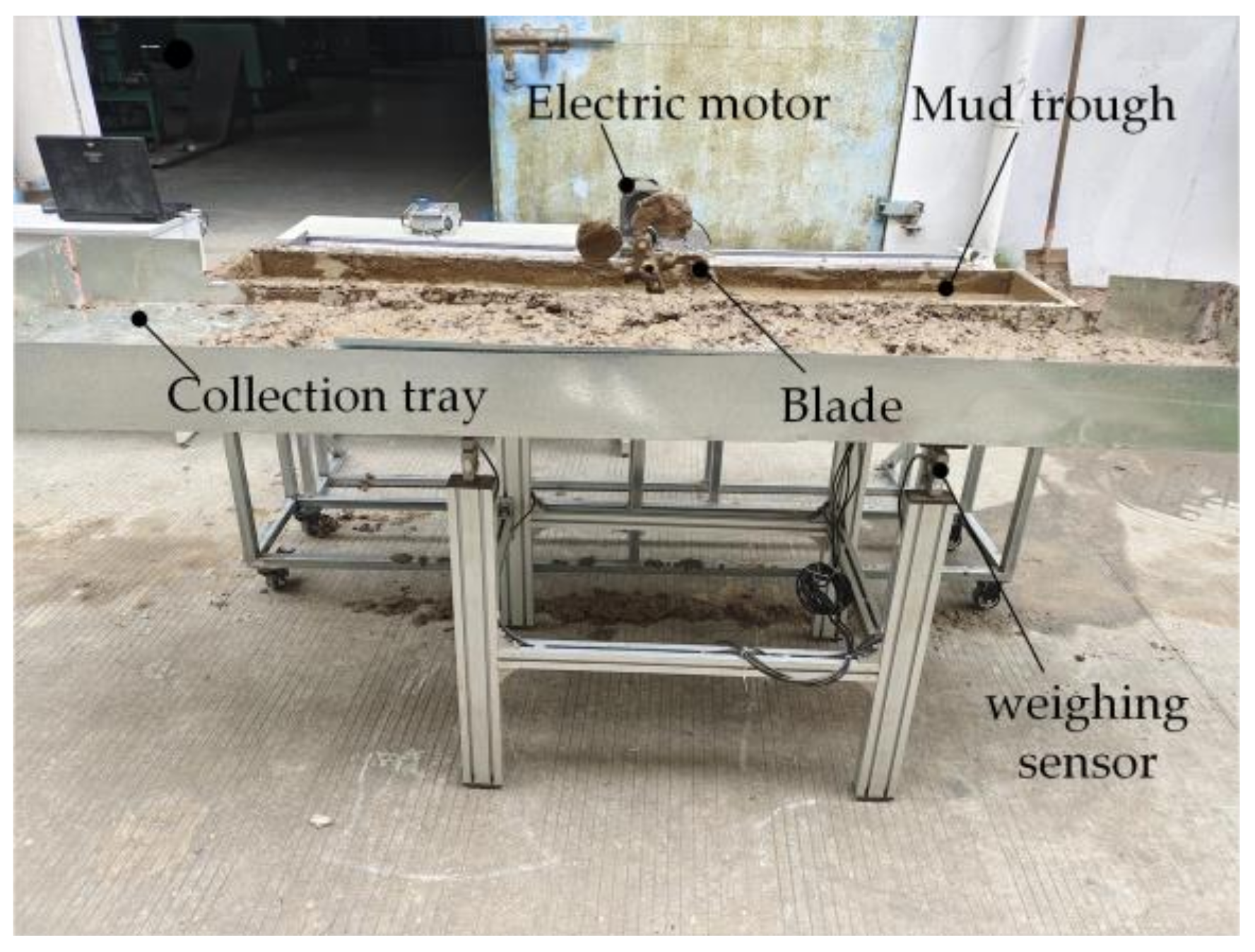
3.4. Bench Experiment
To validate the reliability of the predictive and optimization models for the non-uniformity in spreading, a bench test apparatus was assembled at the College of Mechanical and Electrical Engineering, Fujian Agriculture and Forestry University, Fuzhou, Fujian, as illustrated in Figure 12. The experimental setup comprises an electric motor, a mud trough, blades, a collection tray, and sensors. The blades were fabricated based on the optimization results. Considering the practical operability during the experiment, the optimization conditions were slightly adjusted: X1 (blade rotation radius) was set to 188 mm, X2 (bending angle) was set to 121°, X3 (sub-blade tilt angle) was set to 30°, X4 (forward speed) was set to 400 mm/s, and X5 (rotation speed) was set to 191 r/min. Under these conditions, the predicted value of non-uniformity in spreading is 29.63%. During the test, the motor drove the blade to spray the mud from the tank onto the adjacent collection tray. This operation was sustained for a duration of 5 seconds. Subsequently, a weighing sensor (ZEMIC., Ltd., H8C-C3-1.5T-4B, Downey, CA, USA) was utilized to measure the total weight of mud accumulated in the collection tray. The non-uniformity index during this bench test was then calculated using the method outlined in Section 2.3.4. The relevant data obtained after the test are shown in Table 4.

Figure 12.
Testing apparatus.
Table 4.
Comparison of relative errors between theoretical and experimental values.
From Table 4, it is observed that the non-uniformity in spreading values obtained from the bench experiment are slightly higher than those from the simulation experiment. This suggests that under the same operating conditions, the actual uniformity in spreading of the mud spreader blades is slightly lower than the optimized results from the simulation experiment. The distribution of mud particles on the collection tray is relatively uniform, without adverse phenomena such as accumulation or particle agglomeration. The average relative error between the theoretical and experimental values of uneven spreading is 7.67%, indicating that the predictive model for the non-uniformity in spreading established in this study exhibits good accuracy and reliability, effectively predicting the uniformity of mud spreading. The potential reasons for the error may be variations in external conditions, such as mud viscosity, density, and particle size distribution, which can change over time, and external factors like temperature and humidity during the experiment. These variations could alter the motion state of mud particles during mud spreading, affecting uniform spreading. However, the error is within an acceptable range. Operating under the optimized structure and working parameters resulted in a stable operation with an average improvement of 31.19% in uniformity compared to the pre-optimized state (average non-uniformity in spreading before optimization was 46.66%), meeting the agronomic requirements for rice seedling cultivation during the planting process.
4. Conclusions
In this study, theoretical analysis, simulation, and bench testing were employed to optimize the parameters of paddy field mud spreader blades. The optimized blades can meet the agronomic requirements of paddy field seedling cultivation during operation. The conclusions of this research are as follows:
- The trajectory equations governing the movement of mud particles were established, and a discrete element simulation model was developed to simulate the interaction between the mud spreader blade and mud particles. A second-order orthogonal rotation combined design experiment was conducted to obtain a regression predictive model for quantifying the non-uniformity in spreading with respect to the blade parameters. The accuracy of both the proposed simulation model and regression predictive model was validated through bench tests.
- The response surface methodology was utilized to construct a regression model for the objective function, and analysis of variance was employed to determine the significance of first-order, square terms, and interaction terms on the objective function. The results of the variance analysis indicated that the first-order terms, including rotation radius, bending angle, and forward velocity, significantly influenced non-uniformity in spreading. Additionally, the square terms for rotation radius, sub-blade tilt angle, and rotational speed had a significant impact on non-uniformity in spreading. Among the interaction terms of the second order, the interaction effects of the sub-blade tilt angle with forward velocity and the sub-blade tilt angle with rotational speed were not significant, while the interactions of other factors demonstrated significant effects on the non-uniformity in spreading.
- A multivariate single-objective optimization approach was employed to establish an optimization model for the non-uniformity in spreading. The results indicated that the optimized value for non-uniformity in spreading was achieved at a rotation radius of 188 mm, a bending angle of 121°, a sub-blade tilt angle of 30°, a forward velocity of 400 mm/s, and a rotational speed of the blade at 191 r/min.
- The optimized blade parameters were validated through bench tests. The experimental results closely aligned with the simulated results, with a relative error of 7.67% for non-uniformity in spreading. Furthermore, the optimized uniformity of mud spreading increased by 31.19%, indicating that the optimized parameters can meet the planting requirements for rice seedling cultivation in paddy fields.
Author Contributions
Conceptualization, J.R.; methodology, J.R.; software, C.C.; validation, S.Z.; formal analysis, C.C.; investigation, D.B.; resources, X.W.; data curation, D.B.; writing—original draft preparation, J.R.; writing—review and editing, J.R.; visualization, X.W.; supervision, S.Z. and X.W.; project administration, S.Z.; funding acquisition, S.Z. All authors have read and agreed to the published version of the manuscript.
Funding
This research was funded by the school fund of Fujian Agriculture and Forestry University (grant number K1520005A05); Fujian University Engineering Research Center for Modern Agricultural Equipment (grant number PTJH17004); and Fujian Provincial Science Foundation of China (grant number 2017N0004).
Institutional Review Board Statement
Not applicable.
Data Availability Statement
The data will be made available upon reasonable request from the corresponding authors.
Acknowledgments
The authors would like to express their gratitude to Huang Wenbin from Chongqing University and their laboratory, as well as to the reviewers who provided helpful suggestions for this manuscript.
Conflicts of Interest
The authors declare no conflicts of interest.
References
- Liao, P.; Meng, Y.; Chen, Y.; Weng, W.; Chen, L.; Xing, Z.; Guo, B.; Wei, H.; Gao, H.; Zhang, H. Potted-Seedling Machine Transplantation Simultaneously Promotes Rice Yield, Grain Quality, and Lodging Resistance in China: A Meta-Analysis. Agronomy 2022, 12, 3003. [Google Scholar] [CrossRef]
- Xing, Z.P.; Hu, Y.J.; Qian, H.J.; Cao, W.W.; Guo, B.W.; Wei, H.Y.; Xu, K.; Huo, Z.Y.; Zhou, G.S.; Dai, Q.G. Comparison of yield traits in rice among three mechanized planting methods in a rice-wheat rotation system. J. Integr. Agric. 2017, 16, 1451–1466. [Google Scholar] [CrossRef]
- Liu, W.; Tian, S.; Wang, Q.; Jiang, H. Key Technologies of Plug Tray Seedling Transplanters in Protected Agriculture: A Review. Agriculture 2023, 13, 1488. [Google Scholar] [CrossRef]
- Yang, Z.; Zhu, Y.; Zhang, X.; Liao, Q.; Fu, H.; Cheng, Q.; Chen, Z.; Sun, Y.; Ma, J.; Zhang, J.; et al. Unmanned Aerial Vehicle Direct Seeding or Integrated Mechanical Transplanting, Which Will Be the Next Step for Mechanized Rice Production in China?—A Comparison Based on Energy Use Efficiency and Economic Benefits. Energy 2023, 273, 127223. [Google Scholar] [CrossRef]
- Arredondo-Arredondo, J.J.; Ortiz-Laurel, H.; Rössel-Kipping, D.; Morales-García, D. Evaluation of the Performance of Three Types of Draught Animal Plows. Agrociencia 2003, 37, 187–194. [Google Scholar]
- Li, L.; Chen, J.; Ma, C.; Meng, H.; Qi, J.; Li, Y.; Zhang, P.; Lian, G.; Qi, Z. Study on Soil Throwing Performance and Ditch Depth Stability of Ditching Device in Sandy Orchards in Southern Xinjiang. Appl. Sci. 2021, 11, 12058. [Google Scholar] [CrossRef]
- Sun, Z.; Liang, Y.; Xi, G. Numerical Simulation of the Flow in Straight Blade Agitator with the Mps Method. Int. J. Numer. Methods Fluids 2011, 67, 1960–1972. [Google Scholar] [CrossRef]
- Liu, M.; Hu, C.; Ku, H.; Cai, H. Investigation of Operating Performance of Single-Side Paddy Field Ridger Based on Discrete Element Method and Test Verification. J. Agric. Sci. Technol. 2022, 24, 603–616. [Google Scholar]
- Modak, S.P.; Dogra, B.; Dogra, R.; Kumar, D. Design of Rotary Weeder Blade. AMA Agric. Mech. Asia Afr. Lat. A. 2016, 47, 32–40. [Google Scholar]
- Jia, H.; Ma, C.; Tong, J. Study on universal blade rotor for rototilling and stubble-breaking machine. Soil Tillage Res. 2007, 94, 201–208. [Google Scholar]
- Wang, Y.; Li, D.; Nie, C.; Gong, P.; Yang, J.; Hu, Z.; Li, B.; Ma, M. Research Progress on the Wear Resistance of Key Components in Agricultural Machinery. Materials 2023, 16, 7646. [Google Scholar] [CrossRef]
- Zhu, H.; Wang, D.; He, X.; Shang, S.; Zhao, Z.; Wang, H.; Tan, Y.; Shi, Y. Study on Plant Crushing and Soil Throwing Performance of Bionic Rotary Blades in Cyperus esculentus Harvesting. Machines 2022, 10, 562. [Google Scholar] [CrossRef]
- Wang, B.; Chen, M.; Wei, J.; Liang, G.; Liang, K. Bionic Optimization Design of Rotary Tiller Based on Fuzzy Algorithm. Mob. Inf. Syst. 2022, 2022, 1203973. [Google Scholar] [CrossRef]
- Yang, Y.; Tong, J.; Huang, Y.; Li, J.; Jiang, X. Biomimetic Rotary Tillage Blade Design for Reduced Torque and Energy Requirement. Appl. Bionics Biomech. 2021, 2021, 8573897. [Google Scholar] [CrossRef] [PubMed]
- Xu, G.; Xie, Y.; Liang, L.; Ding, Q.; Xie, H.; Wang, J. Straw-Soil-Rotary Blade Interaction: Interactive Effects of Multiple Operation Parameters on the Straw Movement. Agronomy 2022, 12, 847. [Google Scholar] [CrossRef]
- Zhang, J.; Xia, M.; Chen, W.; Yuan, D.; Wu, C.; Zhu, J. Simulation Analysis and Experiments for Blade-Soil-Straw Interaction under Deep Ploughing Based on the Discrete Element Method. Agriculture 2023, 13, 136. [Google Scholar] [CrossRef]
- Cheng, J.; Zheng, K.; Xia, J.; Liu, G.; Jiang, L.; Li, D. Analysis of Adhesion between Wet Clay Soil and Rotary Tillage Part in Paddy Field Based on Discrete Element Method. Processes 2021, 9, 845. [Google Scholar] [CrossRef]
- Yang, W.; Xiao, X.; Pan, R.; Guo, S.; Yang, J. Numerical Simulation of Spiral Cutter–Soil Interaction in Deep Vertical Rotary Tillage. Agriculture 2023, 13, 1850. [Google Scholar] [CrossRef]
- Zhang, X.; Zhang, L.; Hu, X.; Wang, H.; Shi, X.; Ma, X. Simulation of Soil Cutting and Power Consumption Optimization of a Typical Rotary Tillage Soil Blade. Appl. Sci. 2022, 12, 8177. [Google Scholar] [CrossRef]
- Yuan, Y.; Wang, J.; Zhang, X.; Zhao, S. Effect of Rotary Speed on Soil and Straw Throwing Process by Stubble-Crushing Blade for Strip Tillage Using DEM-CFD. Agriculture 2023, 13, 877. [Google Scholar] [CrossRef]
- Wang, J.; Xiang, Y.; Wang, C.; Xu, C.; Zhu, G.; Gu, Z.; Wang, J.; Tang, H. The Method and Experiment of Kinetic Determination for the Rotary Soil-Engaging Components of Agricultural Machinery Using a Compacting Device in a Paddy Field as an Example. Agronomy 2023, 13, 775. [Google Scholar] [CrossRef]
- Ahmad, F.; Qiu, B.; Ding, Q.; Ding, W.; Khan, Z.; Shoaib, M.; Chandio, F.A.; Rehim, A.; Khaliq, A. Discrete Element Method Simulation of Disc Type Furrow Openers in Paddy Soil. Int. J. Agric. Biol. Eng. 2020, 13, 103–110. [Google Scholar] [CrossRef]
- Du, J.; Heng, Y.; Zheng, K.; Luo, C.; Zhu, Y.; Zhang, J.; Xia, J. Investigation of the Burial and Mixing Performance of a Rotary Tiller Using Discrete Element Method. Soil Tillage Res. 2022, 220, 105349. [Google Scholar] [CrossRef]
- Gao, J.; Shen, Y.; Ma, B. Optimized Design of Touching Parts of Soil Disinfection Machine Based on Strain Sensing and Discrete Element Simulation. Sensors 2023, 23, 6369. [Google Scholar] [CrossRef]
- Cheng, J.; Xia, J.; Zheng, K.; Liu, G.; Wei, Y.; Liu, Z.; Li, P.; Liu, H. Construction and Analysis of a Discrete Element Model for Calculating Friction Resistance of the Typical Rotary Blades. Comput. Electron. Agric. 2023, 214, 108303. [Google Scholar] [CrossRef]
- Li, X.; Zhu, L.; Gong, S. Soil-Cutting Simulation and Dual-Objective Optimization on Tillage Process Parameters of Micro-Tiller by Smoothed Particle Galerkin Modeling and Genetic Algorithm. Comput. Electron. Agric. 2022, 198, 107021. [Google Scholar] [CrossRef]
- Zhang, G.; Zhang, Z.; Xiao, M.; Bartos, P.; Bohata, A. Soil-Cutting Simulation and Parameter Optimization of Rotary Blade’s Three-Axis Resistances by Response Surface Method. Comput. Electron. Agric. 2019, 164, 104902. [Google Scholar] [CrossRef]
- Xin, F.; Xiao, X.; Dong, J.; Zhang, G.; Zhang, Y.; Wu, X.; Li, X.; Zou, Z.; Ma, J.; Du, G.; et al. Large Increases of Paddy Rice Area, Gross Primary Production, And Grain Production in Northeast China During 2000–2017. Sci. Total Environ. 2020, 711, 135183. [Google Scholar] [CrossRef]
- Hu, L.; Xu, Y.; He, J.; Du, P.; Zhao, R.; Luo, X. Design and Test of Tractor-Attached Laser-Controlled Rotary Scraper Land Leveler for Paddy Fields. J. Irrig. Drain. Eng. 2020, 146, 04020002. [Google Scholar] [CrossRef]
- Ucgul, M.; Saunders, C.; Fielke, J.M. Comparison of the Discrete Element and Finite Element Methods to Model the Interaction of Soil and Tool Cutting Edge. Biosyst. Eng. 2018, 169, 199–208. [Google Scholar] [CrossRef]
- Barr, J.B.; Desbiolles, J.M.A.; Fielke, J.M.; Mustafa, U. Development and Field Evaluation of a High-Speed No–till Seeding System. Soil Tillage Res. 2019, 194, 104337. [Google Scholar] [CrossRef]
- Xie, Y.; Ferng, Y.; Miao, J.; Ren, J.; Zhang, X. Numerical and Experimental Study on Optimization of Paddy Field Blade Used in Initial Mud-Cutting Process. Comput. Electron. Agric. 2020, 170, 105243. [Google Scholar] [CrossRef]
- Xie, Y.; Hong, Y.; Zhang, X.; Ren, J. Analysis of Mud Splashing Pattern of Paddy Field Blade Using Computational Fluid Dynamics. Comput. Electron. Agric. 2020, 176, 105639. [Google Scholar] [CrossRef]
- Ani, O.A.; Uzoejinwa, B.B.; Ezeama, A.O.; Onwualu, A.P.; Ugwu, S.N.; Ohagwu, C.J. Overview of Soil-Machine Interaction Studies in Soil Bins. Soil Tillage Res. 2018, 175, 13–27. [Google Scholar] [CrossRef]
- Lee, K.S.; Park, S.H.; Park, W.Y.; Lee, C.S. Strip Tillage Characteristics of Rotary Tiller Blades for Use in a Dryland Direct Rice Seeder. Soil Tillage Res. 2003, 71, 25–32. [Google Scholar] [CrossRef]
- Chen, C.; Di, Z.; Chen, W.; Zheng, S.; Ren, J. Structure Parameter Design and Bench Test Research of Paddy Field Blades. Sci. Rep. 2022, 12, 14733. [Google Scholar] [CrossRef] [PubMed]
- Yu, X.; Zhang, B.; You, J. Mechanism of Drag Reduction in Floating Plate of Paddy Field Based on CFD. Complexity 2020, 2020, 8852941. [Google Scholar] [CrossRef]
- Zhang, Y.; Tian, L.; Cao, C.; Zhu, C.; Qin, K.; Ge, J. Optimization and Validation of Blade Parameters for Inter-Row Weeding Wheel in Paddy Fields. Front. Plant Sci. 2022, 13, 1003471. [Google Scholar] [CrossRef] [PubMed]
- Zhu, D.; Shi, M.; Yu, C.; Yu, Z.; Kuang, F.; Xiong, W.; Xue, K. Tool-Straw-Paddy Soil Coupling Model of Mechanical Rotary-Tillage Process Based on DEM-FEM. Comput. Electron. Agric. 2023, 215, 108410. [Google Scholar] [CrossRef]
- Ding, Q.; Lu, X.; Sun, K.; Li, Y.; He, R.; Wang, X. Performance and Design Parameter Definition on Puddling Knife Using Reverse Engineering. Trans. Chin. Soc. Agric. Mach. 2021, 52, 68–74. (In Chinese) [Google Scholar]
- Matin, M.A.; Hossain, M.I.; Gathala, M.K.; Timsina, J.; Krupnik, T.J. Optimal Design and Setting of Rotary Strip-Tiller Blades to Intensify Dry Season Cropping in Asian Wet Clay Soil Conditions. Soil Tillage Res. 2021, 207, 104854. [Google Scholar] [CrossRef] [PubMed]
- Torotwa, I.; Ding, Q.; Awuah, E.; He, R. Biomimetic Tool Design Improves Tillage Efficiency, Seedbed Quality, And Straw Incorporation During Rototilling in Conservation Farming. J. Agric. Eng. 2023, 54, 1327. [Google Scholar] [CrossRef]
- Pang, C.; Zhuomao, E. Study on the Mud Bedding Device Used on the Rice Seeders. J. China Agric. Univ. 2000, 5, 40–42. [Google Scholar]
- Zhang, X.; Xia, J.; Zhang, J.; He, X.; Liang, S.; Zhang, S.; Wu, H.; Wan, S. Working performance experiment of combination blade roller for straw returning in paddy field and dry land. Trans. Chin. Soc. Agric. Eng. 2016, 32, 9–15. [Google Scholar]
- Xie, Y.; Ren, J.; Zhang, X. Process Analysis and Optimization Design of Blades in Rice Seedling Raising Tray for Mud Homogenizing. J. China Agric. Univ. 2020, 25, 85–94. [Google Scholar]
- Johnson, K.; Kendall, K.; Roberts, A. Surface Energy and the Contact of Elastic Solids. Proc. R. Soc. Lond. A 1971, 324, 301–313. [Google Scholar]
- Wang, H.; Yang, K.; Wang, H.; Wu, J.; Xiao, Q. Statistical Image Analysis on Liquid-Liquid Mixing Uniformity of Micro-Scale Pipeline with Chaotic Structure. Energies 2023, 16, 2045. [Google Scholar] [CrossRef]


Disclaimer/Publisher’s Note: The statements, opinions and data contained in all publications are solely those of the individual author(s) and contributor(s) and not of MDPI and/or the editor(s). MDPI and/or the editor(s) disclaim responsibility for any injury to people or property resulting from any ideas, methods, instructions or products referred to in the content. |
© 2024 by the authors. Licensee MDPI, Basel, Switzerland. This article is an open access article distributed under the terms and conditions of the Creative Commons Attribution (CC BY) license (https://creativecommons.org/licenses/by/4.0/).