Abstract
The extended duration of mulching in Xinjiang cotton fields leads to a significant decline in the tensile strength of plastic film. When recycling is in operation, the soil and the spring teeth of the machinery used can easily cause secondary damage and fracture the residual film. Establishing appropriate working parameters for recycling is essential to enhance the overall quality of collection efforts. By analyzing the motion process of a chain-tooth residual film pickup device, we identified key working parameters that significantly impact the efficiency of recycling. Employing the finite element method (FEM) and a coupled algorithm incorporating smooth particle hydrodynamics (SPH), we developed a coupled finite element model representing the interaction among spring teeth, soil, and residual film. Through simulation and analysis of the process of inserting the spring teeth into the soil to collect film, we derived the governing rules for residual film stress and deformation changes. Utilizing forward speed, rotational angular velocity, and angle of entry into the soil of the spring teeth as test factors and selecting the residual film stress and the residual film deformation as test indices, we conducted a multi-factor simulation test. We established a mathematical model correlating test factors with test indices, and the influence of each factor on the test index was analyzed. Subsequently, we optimized the working parameters of the spring teeth. The results indicated that the optimal working parameters are forward speed of 1111.11 mm/s, rotational angular velocity of 25 rad/s, and angle of entry into the soil of 30°. At these values, the average peak stress of residual film was 4.51 MPa and the height of residual film pickup was 84.48 mm. To validate the optimized the spring teeth impact on performance, field experiments were conducted with recovery rate and winding rate as test indices. The results demonstrated a 92.1% recovery rate and a 1.1% winding rate under the optimal combination of working parameters. The finite element model presented in this paper serves as a reference for designing and analyzing key components of residual film recycling machines.
1. Introduction
The mulching technique reduces losses of water and nutrition from the soil, facilitating enhanced absorption of the essential elements required for crop growth [1,2]. Plastic film is commonly utilized in the cultivation of cash crops such as cotton, wheat, and maize, contributing to improvements in crop quality and yield. However, the predominant choice is a polyethylene film with a thickness ranging from 0.008 to 0.010 mm, which poses a challenge as it requires hundreds of years for natural degradation [3,4,5]. One of the most important means of solving residual film pollution on farmland is mechanical residual film recycling technology. Presently, residual film recycling machinery in China primarily consists of elastic tine, chain tine, telescopic rod tine, and other variations [6,7,8,9,10]. There are many studies on residual film recovery technology, but they mainly focus on the kinematics and dynamics of the residual film pickup mechanism, ignoring the influence of the physical characteristics of the residual film and the soil itself. Due to the poor tensile strength of residual film, the film is easily damaged and can slip off during the recycling process, and the stress and deformation state of the residual film during the recovery process are not clear, resulting in unsatisfactory recovery quality of the residual film.
Fortunately, advancements in computer technology and the availability of commercial engineering software enable the exploration and analysis of challenges that are hard to overcome through traditional theoretical and experimental methods. In the field of agricultural production, with the gradual improvement in ontological models and damage criteria for different types of soils, as well as the gradual introduction of multi-factor and multi-matter coupling techniques, more and more scholars have adopted relevant software to carry out numerical simulation and achieved significant research results. Yang et al. [11] developed a visual dynamic simulation model of an excavating shovel, tuber root, and soil system using an SPH-FEM coupling algorithm and researched the loosening mechanism of the excavating shovel, the deformation, rupture, and thinning processes of the soil, and the stress change process of the tuber roots. Qi et al. [12] adopted an ALE multi-matter coupling algorithm to establish a soil-water finite element model and obtained a working resistance magnitude change rule of a rake pressure-type weeding wheel. Zhang et al. [13] used Abaqus 2016 to establish a simulation model of the interaction between the wheel group of the compaction device and seedbed soil, simulating the process of the interaction between contact components and the soil during compaction. Kang et al. [14] constructed a simulation model of the trenching cutter head using Ansys 16.0 to simulate the cutting process and obtained a change rule of power consumption of the trenching cutter head in the cutting process. These studies highlight that the finite element analysis method is effective in expressing the dynamic response characteristics of each substance during interactions in multi-material coupling calculations. The process of inserting spring teeth into the soil to collect film is a typical multifactorial nonlinear contact dynamics problem. This is characterized by the extensive deformation of the film and the high strain rate of soil crushing [15,16]. However, the interaction between the spring teeth and the soil-residual film mixtures is complex, comprising shear, friction, extrusion, deformation damage, and other processes. It is of special significance to explore the process of the contact between the spring teeth and the membrane soil agglomerate and optimize the operating parameters of the spring teeth to improve the performance of the recycling device. Based on the traditional Lagrange algorithm to simulate the residual film pickup process of the spring teeth into the soil, it is necessary to consider mesh adaptation characteristics and the model reconstruction phenomenon. This is prone to mesh aberration during the computation, which leads to distortion or termination of the computation. Using SPH-FEM coupling, replacing the traditional soil mesh with smooth particles, and retaining only the Lagrange mesh properties of the residual film and the spring teeth, the film and the soil can be coupled together well, with high solving efficiency and avoiding the above problems.
Therefore, this paper proposes a coupling computational model of the spring teeth, the soil, and the residual film. The soil is discretized into smooth particles, while the residual film and the spring teeth are discretized into finite element mesh. The study involves dynamic simulations of the process in which the spring teeth penetrate the soil to collect the film. Concurrently, a quadratic orthogonal rotating center combination test is employed to optimize the operating parameters of the spring teeth, aiming to enhance the operational effectiveness of recycling, which is of paramount significance.
2. Materials and Methods
2.1. Residual Film Recycling Machines and Principles of Operation
2.1.1. Structure of Machine
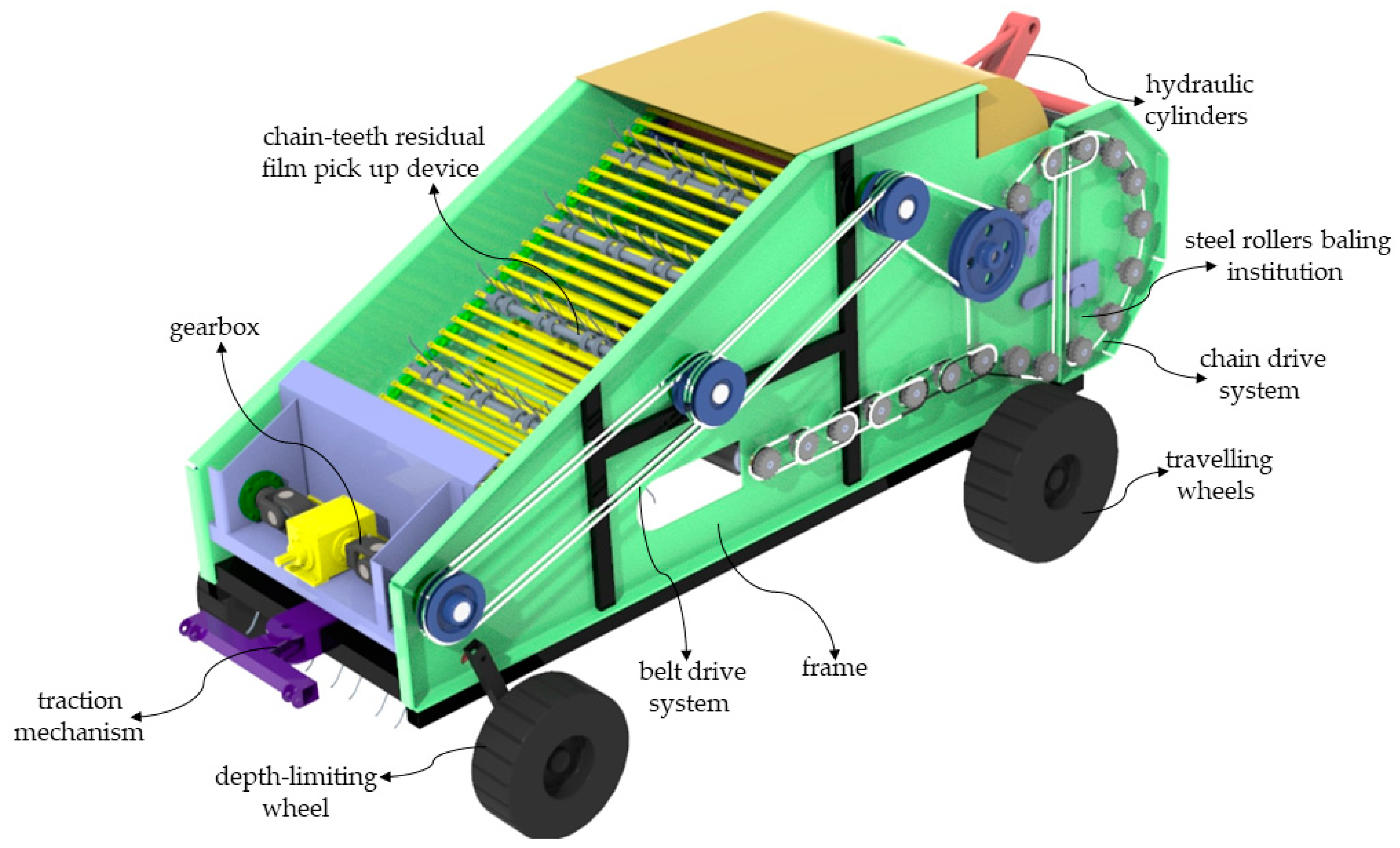
The structure of the residual film recycling and baling machine is shown in Figure 1. It consists of a traction mechanism, a gearbox, a depth-limiting wheel, a belt drive system, a frame, a chain-tooth residual film pickup device, a chain drive system, traveling wheels, hydraulic cylinders, and a steel roller baling institution.

Figure 1.
Machine structure.
2.1.2. Working Process
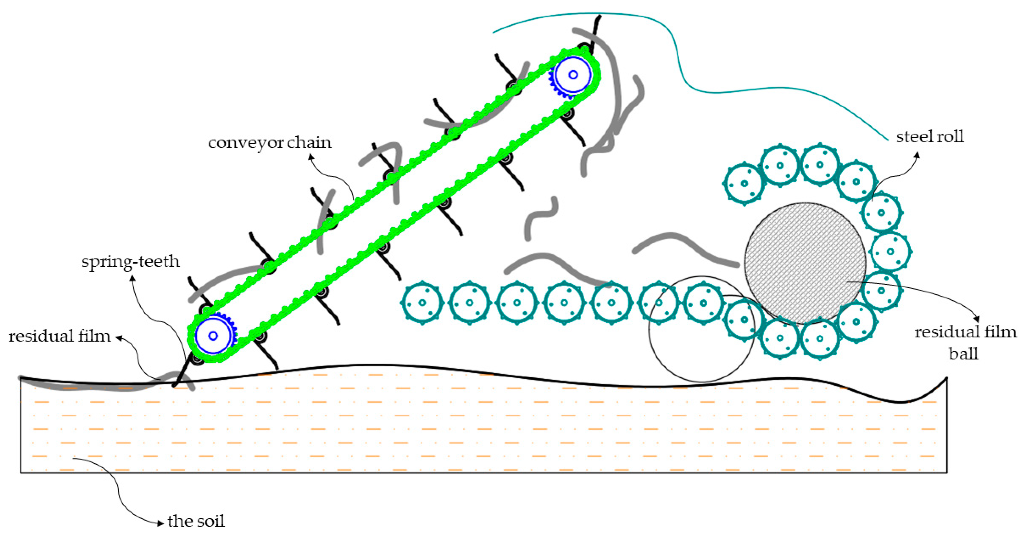
The machine operates with tractor traction, drawing power from the output shaft. The power is transmitted through the gearbox to the chain-tooth residual film pickup device. The spring teeth collect the residual film, and when the film reaches the upper sprocket of the device, the spring teeth rotate downwards, allowing the residual film to fall to the steel roller baling mechanism due to gravity. The chain drive system transfers power to the steel roller baling mechanism, compressing the residual film as the steel roller rotates clockwise for baling. A travel switch in the baling mechanism triggers an alarm when the volume of the residual film bale is significant, disconnecting the switch. At this point, the driver operates the hydraulic system to unload the residual film bale, completing the residual film pickup and baling process, as depicted in Figure 2.

Figure 2.
Working principle diagram.
2.2. Analysis of Operation Process Mechanism of Residual Film Picking Mechanism
2.2.1. Mechanism Structure
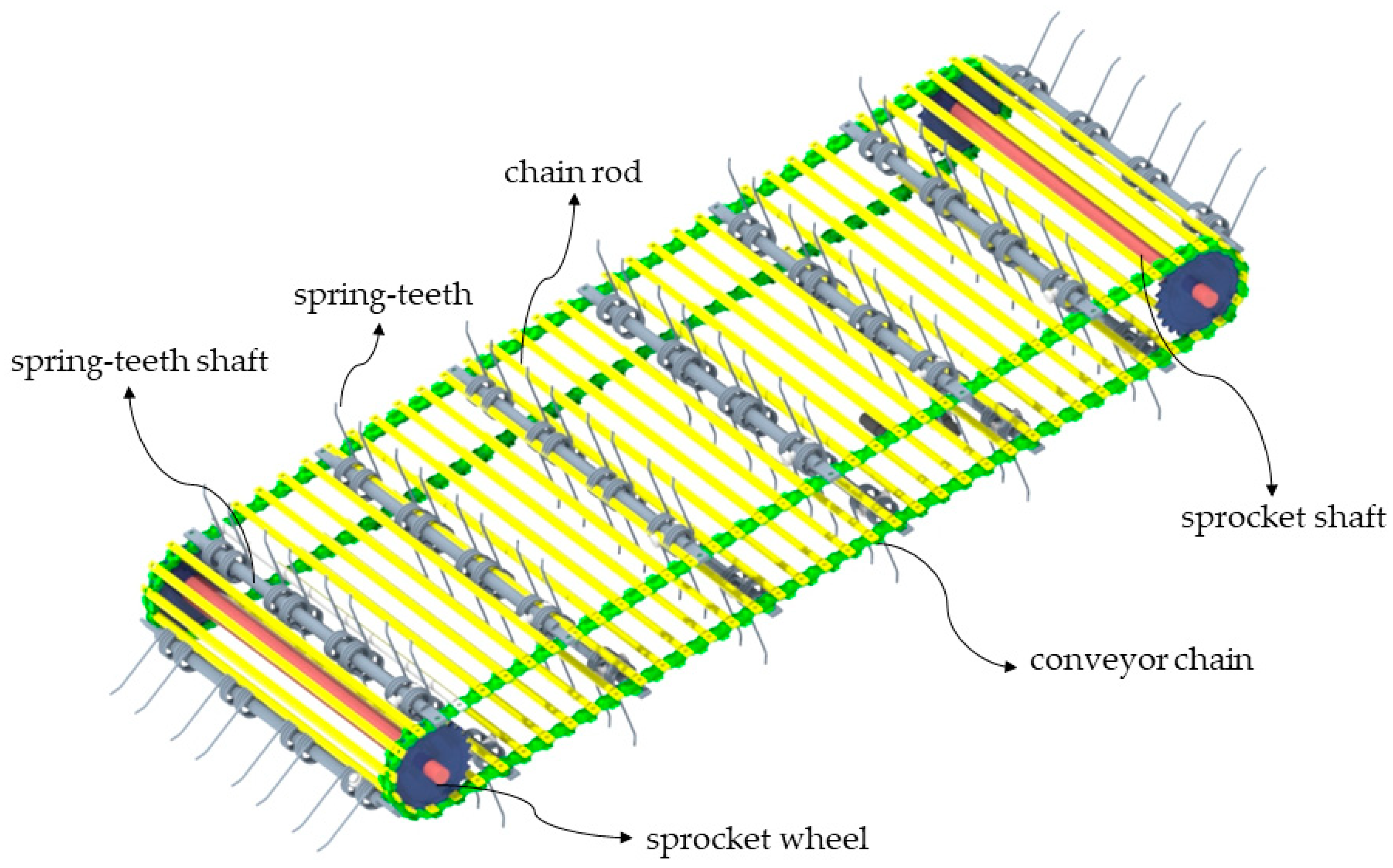
The chain-tooth residual film pickup device is the critical component of the machine, composed of conveyor chain, sprocket shaft, sprocket wheel, chain rod, and spring teeth, as shown in Figure 3. The working direction of the conveyor chain is clockwise, and the function of the conveyor chain is to drive the spring teeth to move according to the set trajectory. The spring teeth penetrate the soil to pickup residual film, facilitating the feeding of residual film.

Figure 3.
The chain-tooth residual film pickup device.
2.2.2. Pickup Process
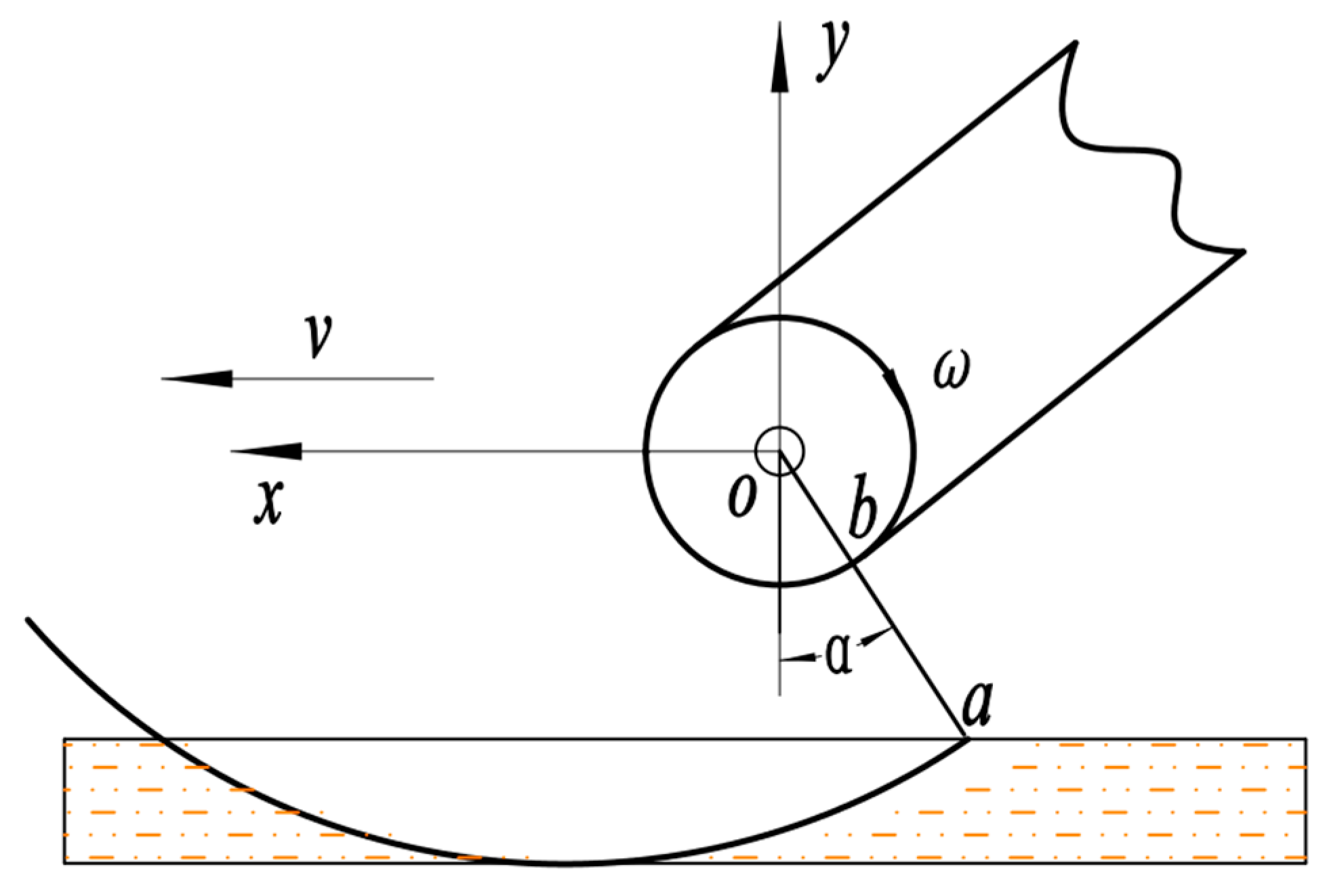
Assuming the x-axis represents the forward direction of the implement in a positive direction, and the y-axis represents a vertical upward direction [17], the motion schematic of the device with forward speed v, sprocket angular velocity ω, and angle of entry into the soil α is illustrated in Figure 4.

Figure 4.
Motion trajectory diagram.
The equation of motion for the tips of the spring teeth is:
Deriving Equation (1), the velocity equation for the tips of the spring teeth is:
where v is the forward speed (km/h); ω is the sprocket angular velocity (rad/s), α is the angle of entry into the soil (°); and Ioa is the distance from the tips of the spring teeth to center of the sprocket (mm).
From Equations (1) and (2), it is seen that the spring teeth motion trajectory and tooth tip speed are all related to the forward speed v, the sprocket angular velocity ω, and the angle of entry into the soil α.
Based on the pre-experiment findings, to ensure optimal performance while considering work quality and efficiency, the recommended forward speed v for the device typically falls within the range of 4 km/h to 6 km/h. The sprocket wheel rotational speed is generally advised to be in the range of 85 r/min to 145 r/min, corresponding to the sprocket angular velocity ω ranging from 8.89 rad/s to 15.17 rad/s. Effective the spring teeth penetration and wrapping of the film occur when the angle of entry into the soil is maintained between 30° and 40°, and this setup minimizes the risk of slippage when the film emerges from the soil.
The process of picking up residual film is not solely dependent on the parameters of the spring teeth: the physical properties of both the soil and the residual film also influence the effectiveness of the pickup process. This paper proposes to simulate the interaction between the spring teeth and the membrane soil agglomerate by means of a multi-matter coupling technique. This simulation allows for the consideration of changes in the working parameters of the spring teeth and the incorporation of the physical properties of both the soil and the residual film.
In this study, the spring teeth and the residual film are discretized into FEM mesh, while the soil model is discretized into a smooth particle model using a node-centered meshless method [18]. The core theory is the difference theory. Describing the soil wrapped around the residual film in terms of discrete particles, each loaded with various physical parameters such as density, mass, velocity, acceleration, etc., the mechanical behavior of the soil can be obtained by solving the governing equations for the set of particles, effectively circumventing calculation termination issues caused by element distortion in nonlinear calculations. The integral representation for the smooth particle dynamics model of soil is defined as:
where f(x) is the integral representation of the soil model; W(x − x’, h) is a smooth kernel function; x − x’ is the distance between soil particles; h is the smooth length of a particle; and Ω is the support domain for smooth kernel functions at point x.
From the particle approximation, the integral form of the smooth particle model for continuous soils can be written in the discrete particle approximation function as:
where f(xi) is the approximate function at soil particle i; mj is the mass of soil particle j (j = 1, 2, …, N); N is the total number of soil particles in the supporting domain of soil particle j; and pj is the density of soil particle j.
The above formulae show that any function value of soil particle i can be approximated by a weighted average of the corresponding function values of all particles in its compact branch by a smooth kernel function.
At present, there are two main methods for coupling SPH particles with FEM mesh: the virtual particle method and the penalty function method. Although the virtual particle method has high accuracy, it is difficult to generate virtual particles at complex boundaries, and particles may penetrate the boundaries in some cases. The penalty function method is a simple way to achieve the coupling of different finite element mesh types and can handle complex geometric boundary conditions [19].
In the context of solving Navier-Stokes equations, SPH employs the leapfrog scheme, whereas FEM utilizes the central difference scheme to solve the explicit dynamic equation. Within the Lagrange framework, it is crucial for the coupling surfaces of SPH and FEM to be seamlessly synchronized, enabling simultaneous data transmission. Both FEM and SPH adopt identical time steps, expressed as follows:
where h is the smooth length of the particle; cv is the sound velocity of the material; φ is the time-step scale coefficient; and L is the minimum unit size.
The constitutive relationship between the residual film and the soil material has a great influence on the accuracy of the simulation results. In this paper, both the residual film and the soil material are adopted into an elastoplastic constitutive model. An elastoplastic constitutive model can be used to describe the changes in soil material motion characteristics with large deformation and high strain rate [20,21], and its total stress tensor is expressed as:
where σ1 is the total stress tensor of soil particles; p is hydrostatic compression stress; δ is the artificial viscosity coefficient; s is partial shear stress; σm is principal stress; and σx, σy, σz are stress values in the x, y and z directions.
The Drucker-Prager criterion is used to determine plastic failure [22,23]. The yield conditions of the Drucker-Prager criterion are as follows:
where F(I1,J2) is the soil particle yield function; I1 is the first invariant of the stress tensor; J2 is the second invariant of the partial strain tensor; c is the cohesion of soil particles; ϕ is the internal friction angle of soil particles; and ξø, ζø are the material constants calculated from the internal friction angle of soil particles.
The elastoplastic constitutive model can be used to describe the flexible deformation and damage to the residual film under an external load [24]. The total stress tensor of residual film elastoplastic material is expressed as:
where σ2 is total stress tensor of the residual film; F is the external load; A is the cross-section area of the residual film; Δb is the deformation of the residual film; and b is the length of the residual film.
2.3. Finite Element Model Establishments
2.3.1. Parametric Model
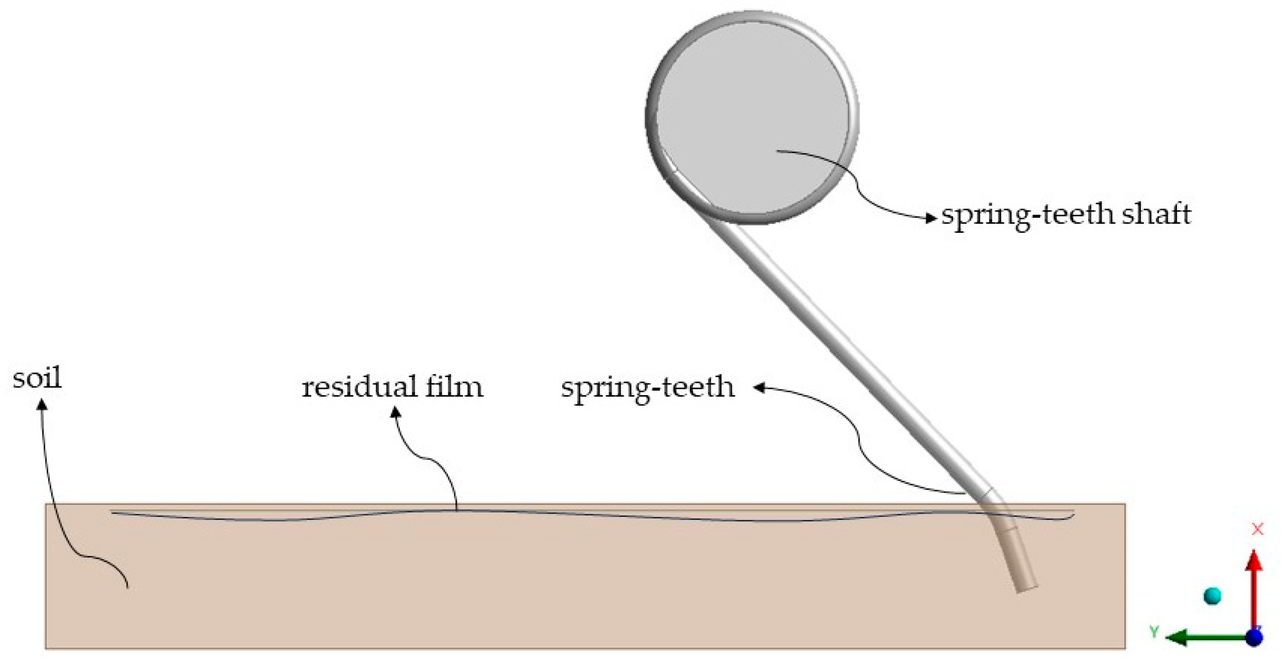
Typically, simulation accuracy improves as the model aligns more closely with real-world scenarios. However, in the actual operation process, to improve the accuracy of the simulation model, it requires more powerful computer hardware. Moreover, simulating various nonlinear problems often entails increased computational load when aiming for enhanced accuracy. To strike a balance between solving accuracy and efficiency, combined with the purpose of this paper, the chain-tooth residual film pickup device is assembled by a number of groups of spring teeth. Each spring teeth in the simulation has the same effect upon contact with the film-soil mixture. The model establishes a specific area of film-soil mixture and a single spring teeth. The parametric model created with Creo 4.0, the soil is represented as a rectangular body and the residual film is embedded within the soil. The dimensions of the residual film are set to a length of 360 mm, a width of 160 mm, and a thickness of 0.01 mm, while the soil dimensions are specified as a length of 400 mm, a width of 200 mm, and a thickness of 50 mm. The parametric model is shown in Figure 5.

Figure 5.
Parametric model.
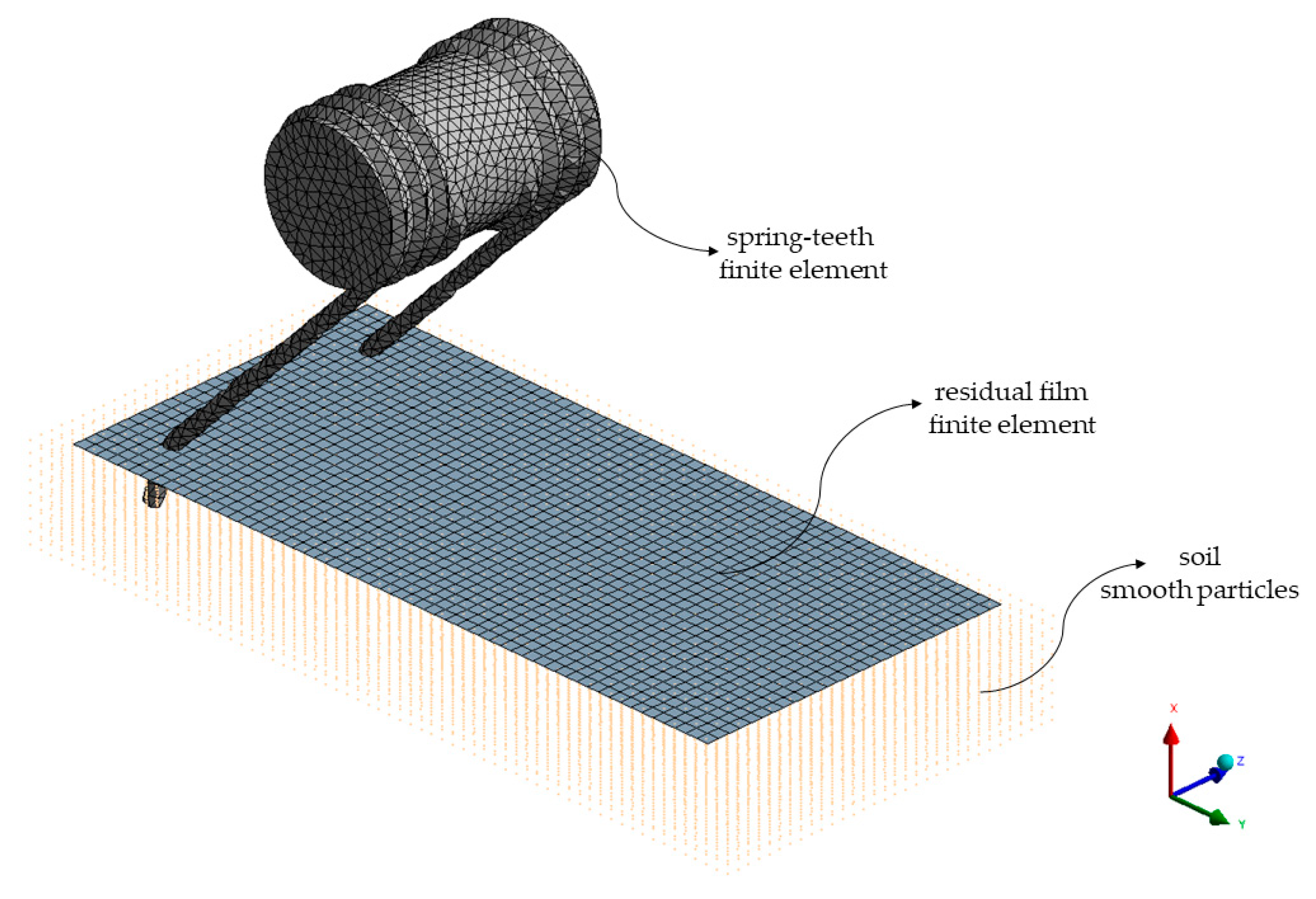
The model file is imported into the Mesh module for finite meshing. The soil model grid is transformed into SPH smooth particles, and the local coordinate system is applied to the bottom of the soil particles. The Lagrange finite element mesh properties of the residual film and the spring teeth are retained, a solid164 element type is selected for the spring teeth, and a shell63 element type is selected for the film [11]. To ensure the accuracy of numerical calculation, the residual film project was divided into 5 mm finite element mesh and the soil project was divided into 5 mm smooth particles. Finally, the number of nodes in the entire simulation model is 38,277 and the number of units is 61,847. The grid division results are shown in Figure 6.

Figure 6.
Finite element mesh division result diagram.
Open the generated model file in LS-Prepost 4.7.7 and define the material parameters by keyword. The material models of the film and the soil use elastoplastic constitutive model [25]. Then, introduce the soil material failure criteria keywords [26]. The material model of the spring teeth use rigid body model. The material parameters of residual film, soil and spring teeth are shown in Table 1 [27].

Table 1.
Simulation material parameters.
2.3.2. Boundary Condition Setting and Solution Calculation
Define forward speed and rotation angular velocity. Firstly, limit the flat movement of the spring teeth in the z-direction and limit the rotation around the x-axis and the y-axis [28], and add the speed of the spring teeth along the y-axis in the positive direction. When the forward speed of the machine is 4–6 km/h, the speed of the spring teeth along the y-axis in the positive direction is 1111.11–1666.67 mm/s. To guarantee solving efficiency and avoid multi-object interference leading to the error or termination of the solving results, the finite element model is simplified by removing the conveyor chain, the sprocket and other components [29,30] according to the previous analysis of sprocket angular velocity ω in the 8.89–15.17 rad/s range. To ensure that tooth tip speed is the same after simplification, the calculation needs to be added to the spring teeth around the z-axis direction of the rigid body rotational angular velocity of 15–25 rad/s. During the operational phase, when the spring teeth come into contact with the membrane soil agglomerate, both normal contact and tangential slip occur. Define the contact properties and tangential action between the three items as a penalty function. Controlled through use of the contact surface-to-surface automatic keyword [31].
For improving the speed and accuracy of computation, the model file is uploaded to the cloud computing platform for solving and the resultant file is downloaded from the cloud computing platform to the local computer for post-processing after the solving is completed.
3. Results and Analysis
3.1. Properties of Residual Film in Process of Picking Up
In order to validate the reliability of the finite element simulation method, an analysis of dynamic characteristics, stress and deformation of the residual film was conducted. This analysis focused on specific parameters: a forward speed of 1388.5 mm/s, a rotational angular velocity of 20 rad/s, and an angle of entry into the soil of 35° as an illustrative example.
3.1.1. Residual Film Dynamic Characteristics
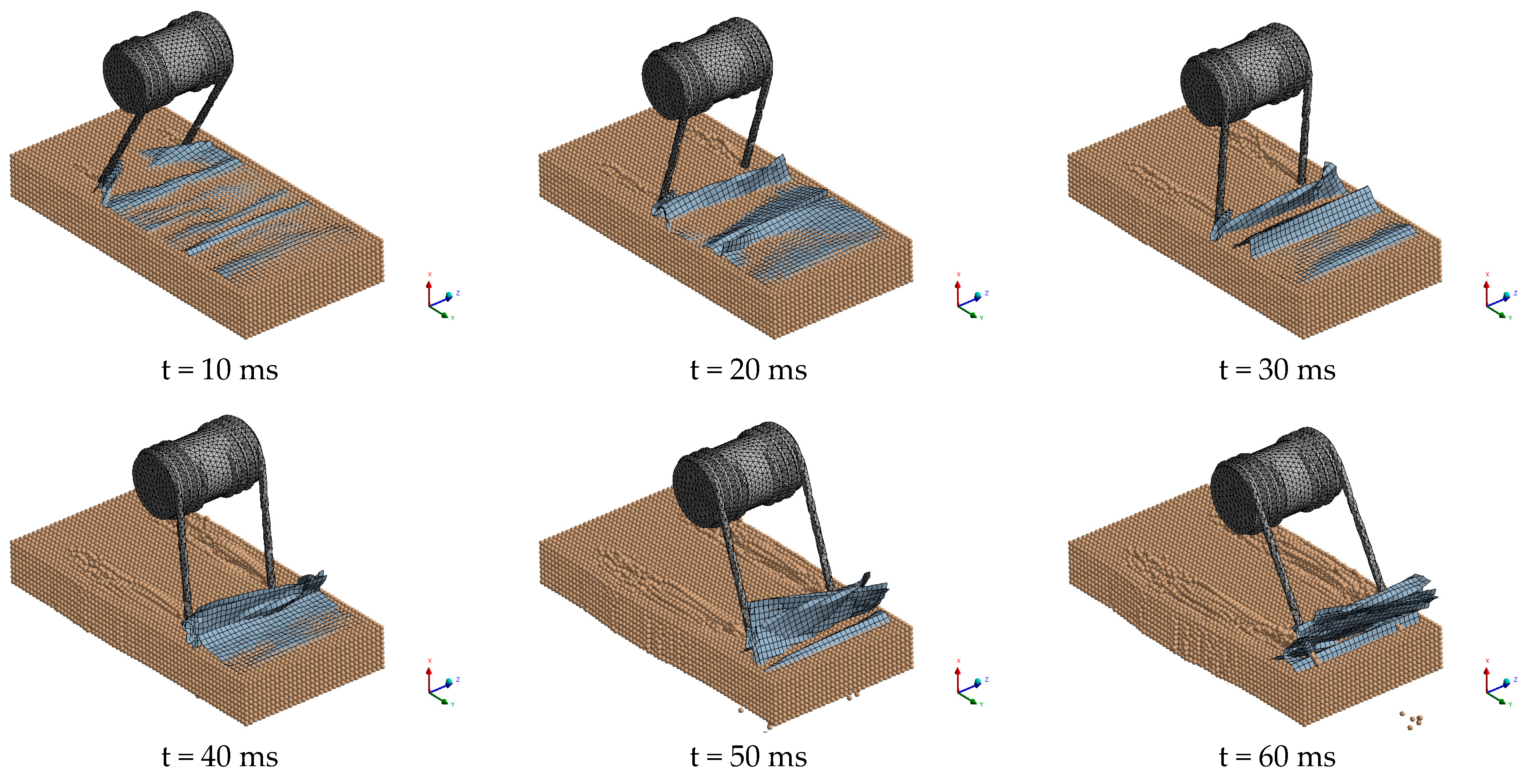
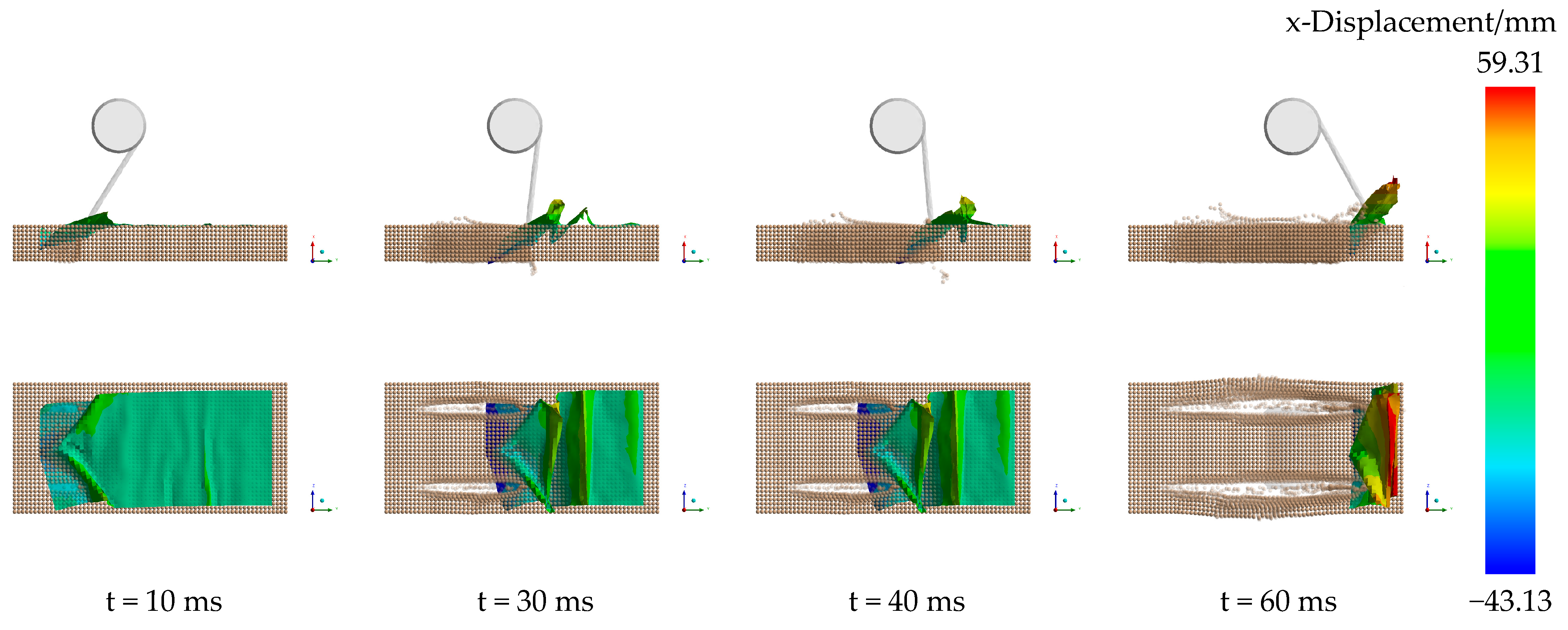
The process of the spring teeth entering the soil to pickup the residual film is shown in Figure 7, where the spring teeth are in the process of wrapping the film in 0–30 ms time period and picking it up in the 30–60 ms time period. At t = 10 ms, as the spring teeth approach the soil, soil extrusion initiates from the tooth tip, resulting in cracking. The residual film in the spring teeth, subjected to the contact position, experience a certain degree of plastic deformation and exhibit a flexural state. At time t = 30 ms, the spring teeth propel the film in the soil to slide forward, and the soil is further destroyed. When t = 40 ms, the spring teeth emerge from the soil, successfully picking out the residual film. The residual film exhibits a noticeable fold state at this stage. At the end of the simulation time at t = 60 ms, the residual film will hang in the spring teeth on the tooth tips and the soil by the spring teeth to the maximum degree of perturbation. In this process, the spring teeth are always in full contact with the residual film, and the finite element simulation model can effectively express the whole process of wrapping and picking up the residual film with the spring teeth into the soil.

Figure 7.
Residual film dynamic characteristics.
3.1.2. Residual Film Stress Changes
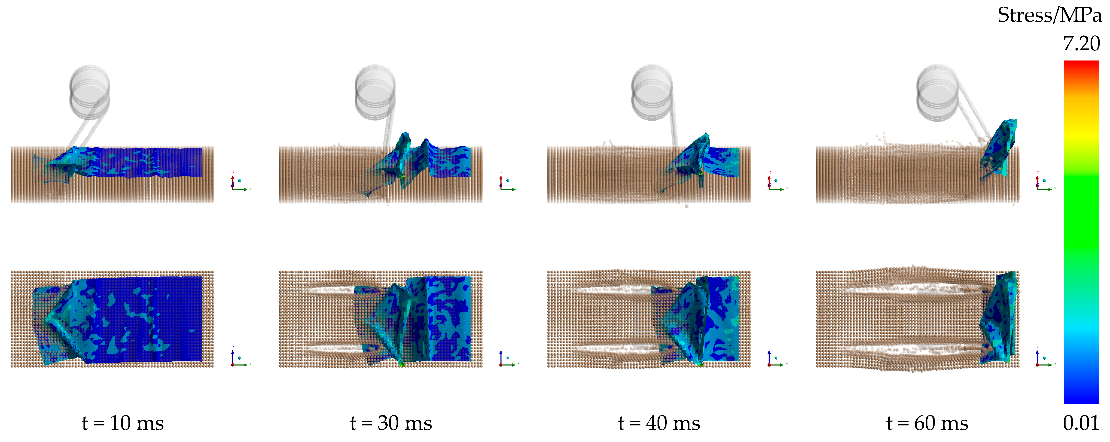
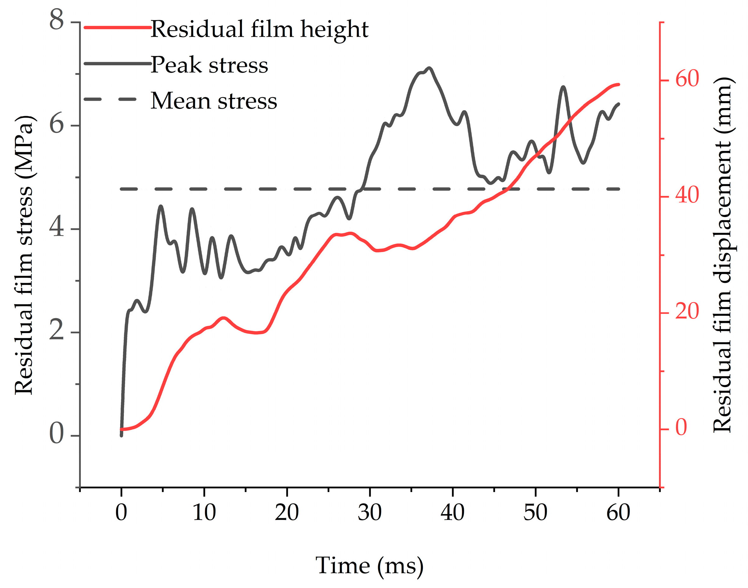
The variation rule of residual film stress is shown in Figure 8 and Figure 9. At time t = 10 ms, the residual film stress is mainly concentrated in the tooth tips and the residual film contact position; the residual film peak stress is 2.87 MPa. Furthermore, the sliding of the residual film within the soil is accompanied by a noticeable alteration in stress values. As the spring teeth continue to wrap around the film over time, the stress values exhibit a consistent increase. At t = 30 ms, the stress in the residual film is primarily concentrated at the location where folds occur, with a peak stress value of 5.39 MPa. When the spring teeth start to pickup a portion of the film from the soil at t = 40 ms, the peak stress in the residual film increases to 6.03 MPa. During this time, the residual film stress is mainly concentrated precisely at the point where the residual film separates from the soil. At the end of the simulation time, t = 60 ms,. the peak stress of the residual film is concentrated near the tooth tip position; the stress value is 6.42 MPa. In the simulation process, the maximum peak stress of the residual film is 7.20 MPa and its average peak stress is 4.77 MPa [24]. Deformation and sliding of the residual film escalate mechanical forces between the spring teeth and the soil acting on the residual film. The process of picking up the residual film requires balancing the excessive spring teeth force on the film prevents detachment and overcomes the friction between the film and the soil for complete separation. Lower stress during the pickup process indicates lesser force applied to the residual film by the spring teeth and the soil, reducing further film destruction and enhancing the recycling rate.

Figure 8.
Residual film stress distribution.

Figure 9.
Residual film value change curve.
3.1.3. Residual Film Deformation Changes
The variation rule of residual film deformation is shown in Figure 9 and Figure 10. Specifically, these figures focus solely on the deformation of the residual film in the x-axis direction, which corresponds to the displacement of the residual film from the ground. This value is also defined as the height of residual film pickup. As the spring teeth enter the soil at t = 10 ms, a portion of the residual film starts sliding within the soil. In addition to the occurrence of mild folds, a bulging effect is observed in the residual film where it is affected by both the spring teeth and the soil. At this moment, the residual film deformation, also representing the height of the residual film during the pickup process, is 17.56 mm. As the simulation progresses to t = 30 ms, the spring teeth continue to play a role, causing further folding in the residual film, resulting in a deformation of 31.56 mm. With the passage of simulation time, the residual film is gradually picked up from the ground, and at t = 40 ms, the residual film deformation reaches 36.69 mm. At the simulation conclusion, t = 60 ms, a significant portion of the residual film is lifted, with some hanging on the tooth tips, causing the maximum residual film deformation to reach 59.31 mm. This maximum deformation is considered the final height of the residual film pickup. This analysis demonstrates that the height of the residual film pickup increases as the simulation progresses, indicating the effectiveness of the spring teeth in picking up the residual film without leakage or slipping. This provides valuable insight for selecting simulation test indices in subsequent studies.

Figure 10.
Residual film x-deformation.
3.2. Multi-Factor Simulation Optimization Tests
3.2.1. Simulation Test Program
To obtain the optimal operating parameters of the spring teeth, a quadratic orthogonal rotational combination design was used to conduct virtual simulation tests with forward speed (x1), rotational angular velocity (x2), and angle of entry into the soil (x3) of the spring teeth as the experimental factors, and with the average peak stress of the residual film (Y1) and the height of residual film pickup (Y2) as the test indicators. The experimental factor levels are shown in Table 2.
Table 2.
Coding of experimental factors.
3.2.2. Analysis of Test Results
Simulation tests were carried out as described above, and each group was repeated three times to calculate the average value of the average peak stress of the residual film (Y1) and the height of pickup (Y2). The experimental results are shown in Table 3.
Table 3.
Experimental results.
We conducted a multiple regression fitting analysis using the test results to establish a regression model correlating forward speed (x1), rotational angular velocity (x2), and angle of entry into the soil (x3) of the spring teeth with both the average peak stress of the residual film (Y1) and the height of pickup (Y2) [32]. The results of the analysis of variance (ANOVA) for the model are presented in Table 4.
Table 4.
Analysis of variance.
The regression model for the average peak stress of the residual film, with a significance level of p < 0.01, indicates high significance. Among the primary terms, both x1 and x2 exhibit high significance, while x3 shows significance. Among the interaction terms, significance is observed for x1x2, whereas x1x3 and x2x3 display no significance. Regarding secondary terms, x32 demonstrates high significance, while x12 and x22 do not show significance.
The significance of the regression model for the height of residual film pickup, denoted by p < 0.01, highlights its high significance. Among the primary terms, x2 exhibits high significance, while x1 and x3 do not show significance. Additionally, the interaction terms x1x2, x1x3, and x2x3 demonstrate no significance. The secondary terms x12, x22, and x32 also lack significance in the model.
We established a regression equation to formulate a mathematical model that correlates the average peak stress of the residual film (Y1) and the height of residual film pickup (Y2) with forward speed (x1), rotational angular velocity (x2), and angle of entry into the soil (x3), respectively:
To quantitatively evaluate the accuracy of the regression model, the determination coefficient R was used to evaluate the fitting effect of the mathematical model. The determination coefficients of (Y1) and (Y2) were 0.9517 and 0.9315, respectively, which are both greater than 0.85, indicating that the predicted value of the established model is in good agreement with the experimental value. Therefore, (Y1) and (Y2) can be analyzed and optimized with this model.
3.2.3. Response Surface Analysis
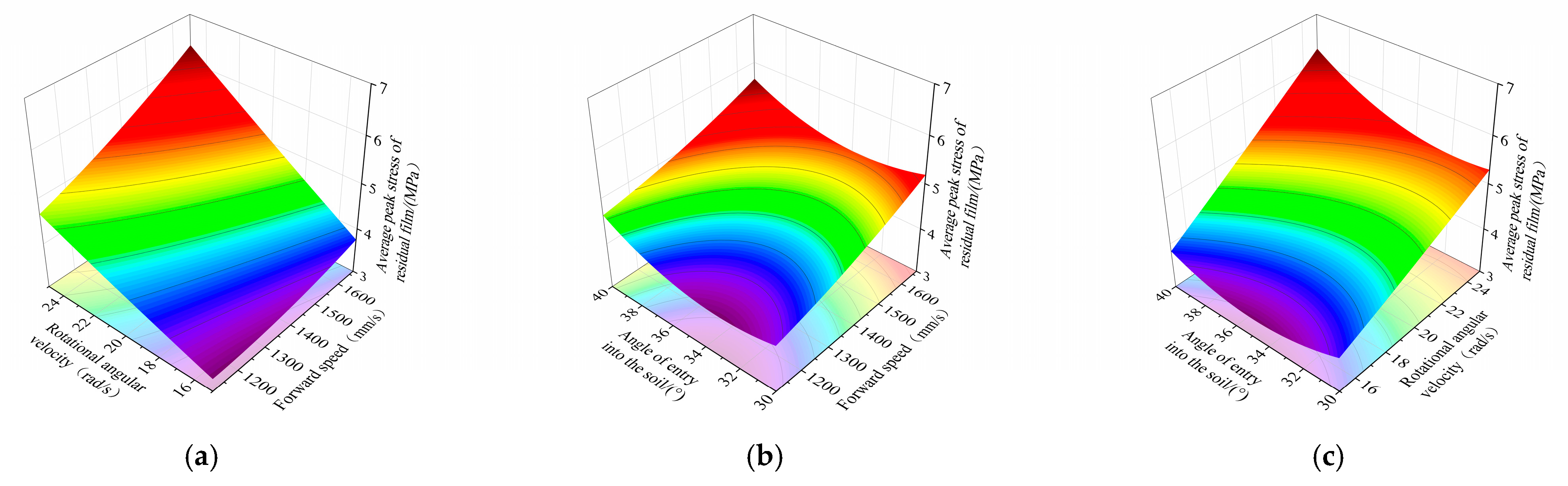
In Figure 11a, it is clear that when the forward speed is 1388.5 mm/s, the average peak stress of the residual film gradually increases with rising rotational angular velocity. However, at a rotational angular velocity of 25 rad/s, there is a significant increasing trend in the average peak stress of the residual film as the forward speed increases. In Figure 11b, as forward speed increases, the average peak stress of the residual film increases and changes more rapidly. While the angle of entry into the soil increases, the average peak stress of the residual film increases and changes more slowly. In Figure 11c, it is apparent that when the rotational angular velocity is at an intermediate level, with the increase in angle of entry into the soil, the average peak stress of the residual film first increases and then decreases. Similarly, the average peak stress of the residual film increases gradually with the increase in rotational angular velocity when the angle of entry into the soil is at an intermediate level.

Figure 11.
The influence of experimental factors on the average peak stress of the residual film surface. (a) Y1 = (x1, x2, 0); (b) Y1 = (x1, 0, x3); (c) Y1 = (0, x2, x3); (a) Effect of forward speed-rotational angular velocity on average peak stress of residual film; (b) effect of forward speed-angle of entry into the soil on average peak stress of residual film; (c) effect of rotational angular velocity-angle of entry into the soil on average peak stress of residual film.
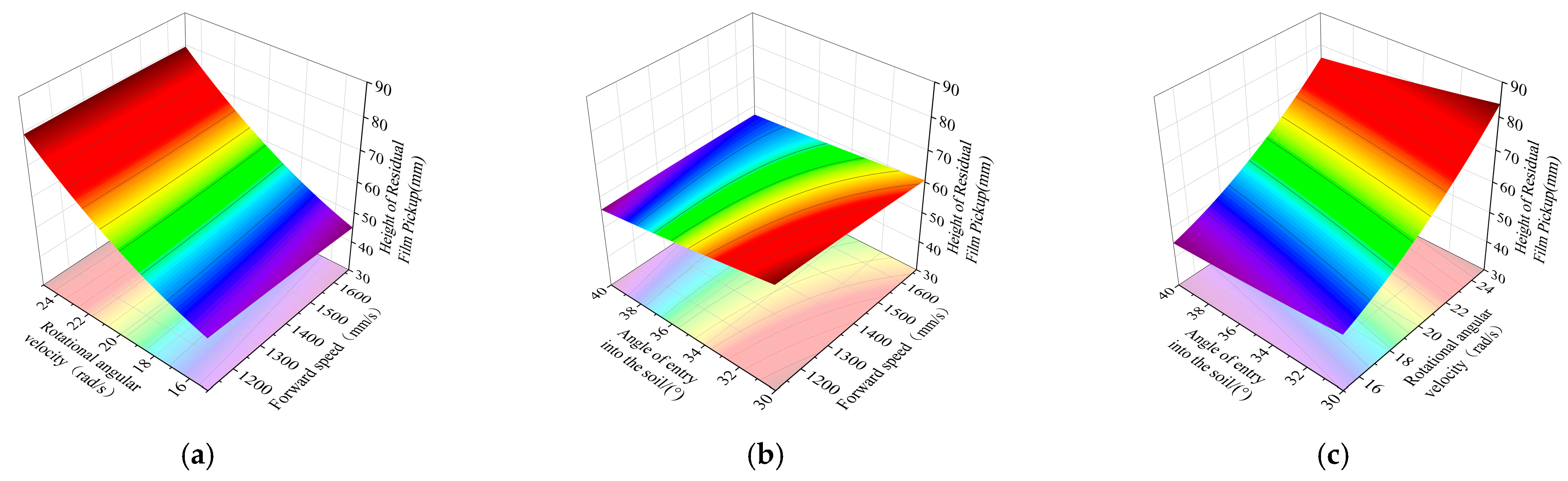
In Figure 12a, when the forward speed is at a low level, the height of the residual film pickup increases rapidly with the increase in rotational angular velocity, but the change in the height of the residual film pickup with forward speed is small and insignificant when rotational angular velocity is in a certain position. Figure 12b depicts the relationship between the interaction between forward speed and angle of entry into the soil and its impact on the height of residual film pickup, when one factor is at a fixed value, the height of residual film pickup does not vary significantly with either forward speed or angle of entry into the soil. In Figure 12c, when the rotational angular velocity is 20 rad/s, the height of residual film pickup increases slowly with the increase in angle of entry into the soil: when angle of entry into the soil is 35°, the height of the residual film pickup increases gradually with the increase in rotational angular velocity.

Figure 12.
The influence of experimental factors on the height of residual film pickup surface. (a) Y2 = (x1, x2, 0); (b) Y2 = (x1, 0, x3); (c) Y2 = (0, x2, x3). (a) Effect of forward speed-rotational angular velocity on height of residual film pickup; (b) effect of forward speed-angle of entry into the soil on height of residual film pickup; (c) effect of rotational angular velocity-angle of entry into the soil on height of residual film pickup.
3.2.4. Optimization
The objective of this study was to mitigate excessive force exerted by the spring teeth and the soil on the residual film, thereby minimizing breakage and reducing the slip effect. Both (Y1) and (Y2) are of equal importance. Using the response optimizer feature in Design Expert 8.0.6.1, a quadratic regression equation was formulated to optimize these constraints. The equation was solved with an operational timing set at 3 “+” to emphasize (Y1) and another 3 “+” to highlight the importance of (Y2).
The optimal combination of operational parameters was determined through calculation: forward speed 1111.11 mm/s, rotational angular velocity 25 rad/s, and angle of entry into the soil 30°. At this optimized configuration, the model predicts the average peak stress of the residual film (Y1) to be 4.51 MPa and the height of residual film pickup (Y2) to be 84.48 mm.
3.3. Field Experiment
3.3.1. Test Conditions
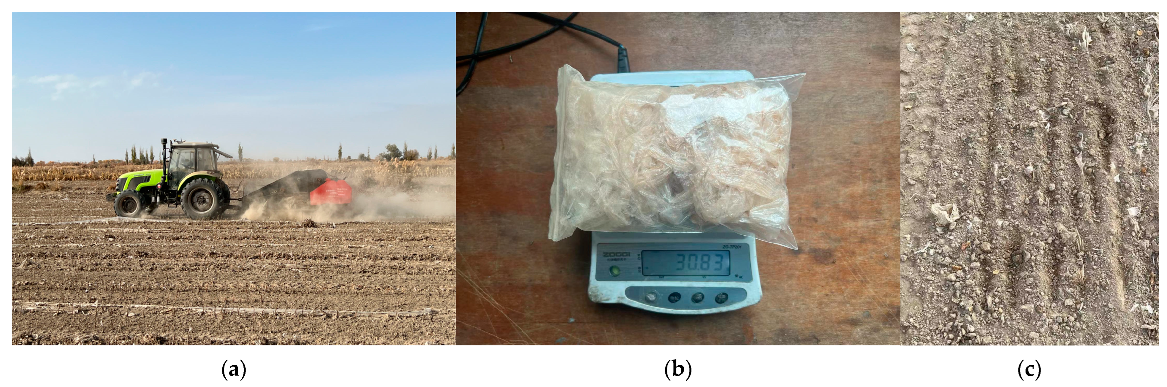
To verify the operation performance of the optimized working parameter combination of the spring teeth obtained by simulation, a field test was conducted in Qiongkule Village, Tarim Township, Weili County, Xinjiang in November 2023, as shown in Figure 13. The test took place in a flat cotton field post-autumnal cotton picking, featuring a film thickness of 0.01 mm and a film width of 2050 mm [33]. The test plot was about 1000 m long and 40 m wide. The soil compactness, measured using a soil compactness tester (Yishida, TYD-2) was determined to be 2611.46 kPa. Simultaneously, the soil moisture content, measured with a soil moisture content tester (Jiekesi, JK-100F) was found to be 17.68% in the test plot at a depth of 0–100 mm. The Zoomlion RC1204-F tractor was selected as the supporting power of the test. The main test equipment included an electronic balance, a Yulide UT373 high-precision digital display tachometer, tape measure, disposable sample bag, marker pen, etc. The optimum operating parameter combination of the spring teeth is forward speed 1111.11 mm/s, rotational angular velocity 25 rad/s, and angle of entry into the soil 30°. Translated for the field test, this equated to a forward machine speed of 4 km/h, a sprocket wheel rotational speed of 145 r/min, and angle of entry into the soil 30°.

Figure 13.
Field experiment. (a) Machine at work; (b) residual film quality calculation; (c) machine operation effect.
3.3.2. Experimental Design
Effectively picking and removing residual film are necessary conditions to ensure the continuous operation of the residual film recovery machine. Therefore, the recovery rate and winding rate of the residual film are selected as the performance evaluation indices of the machine [17]. According to the GB/T14290-2021 round straw baling machine and GB/T25412-2010 residual film recycling machine [34,35], the test plan is formulated. Five sections of 10 m length test area are randomly selected in the test area for test sample collection (there is no overlap area). After removing dust and water, the average weight is calculated to obtain the residual film quality. The recovery rate is calculated according to Equation (18). Simultaneously, the film wrapped on the machine and the film collected in the packing room are collected, and the winding rate is calculated according to Equation (19).
where: S1 is the recovery rate, %; W is the mass of film on the ground after pickup, g; and W0 is the total mass of newly laid surface mulch before pickup, g.
where: S2 is the winding rate, %; M1 is the mass of film winding around the machine, g; and M2 is the film mass of the packing room, g.
3.3.3. Test Result
The field test results are shown in Table 5.
Table 5.
Field performance test results.
As can be seen from Table 5, when the forward machine speed is 4 km/h, the sprocket speed is 145 r/min, the angle of entry into the soil is 30°, the average recovery rate of the machine is 92.1%, and the average winding rate is 1.1%. It can be seen from the operation effect of the machine in Figure 13c that the spring teeth can successfully pickup the residual film from the soil, and only small fragments of residual film remain on the surface of the farmland. There is an obvious gully shape in the place where the spring teeth pass through, and there is obvious disturbance and damage to the soil, which can meet the performance requirements of the machine in field operation.
Under this combination of working parameters, when the forward speed is low, the distance covered by the spring teeth driving the residual film in the soil is shorter. This reduces the friction of the soil against the residual film, thereby reducing the peak stress on the residual film. This condition effectively prevents the occurrence of fracture in the residual film, making it easier to pickup the film and achieving a higher recovery rate. When the forward speed and the angle of entry into the soil are fixed, a higher sprocket speed results in a greater height to which the recovery device lifts the film in the same amount of time. This effectively reduces the sliding distance of the film, mitigating the risk of missing pickup of film and improving the recovery rate. At the same time, the higher the sprocket speed, the greater the vibration of the mechanism, and the winding rate of the mechanism will be effectively reduced. When the angle of entry into the soil is small, the mechanical force of the spring teeth on the film is small and the peak stress value is low, which can effectively avoid the secondary pulling and breaking of the film, thus improving the recovery rate. Moreover, under the combination of the working parameters, the chain-tooth residual film pickup device operates efficiently in continuous working conditions. Driven by the conveyor chain, the spring teeth can smoothly pickup the residual film, and the film can smoothly fall off when it reaches the top of the mechanism, without the phenomenon of secondary winding of film. The function and operation effect of each component meet the design expectations.
3.4. Comparative Analysis with Previous Research Results
In this paper, the recycling process of residual film was studied by theoretical analysis, dynamic simulation and field test. The key factors affecting the pickup process were analyzed theoretically. The finite element model effectively predicted the degree of stress and deformation of the residual film. The maximum peak stress of the residual film was 7.20 MPa, which was close to the maximum stress value of the residual film in the contact analysis of the residual film pickup based on the mechanical characteristics of the residual film by Xie et al. [24]. This proves that the finite element model has high reliability. The optimum working parameter combination of the spring teeth was determined by simulation tests. Field tests were carried out under the optimal working parameters, and the results showed that the residual film retention was less, the recovery rate 92.1%, and the winding rate 1.1%.
In addition, this research group designed a dithering chain film-soil separation de-vice early on. However, during the operation of this mechanism, the machine exhibited significant vibration, resulting in a relatively low recovery rate of residual film of only 68.0% [5]. The recovery effect of the residual film in this earlier design was found to be inferior to that achieved by the machine in the present study. Xie et al. [17]. designed a toothed-chain compound residual film recovery machine, and the test results showed that the recovery rate was 87.2% and the winding rate was 1.6%. Compared with this machine, the experimental results of this study are better. Cao et al. [29]. designed a residual film pickup device and their recovery rate was 88.3 %, which is lower than the recovery rate in this study. Compared with previous studies, the analysis method in this study is more innovative, more intuitive in clarifying the working process, and reveals the mechanism of stress and deformation of the residual film. This work provides theoretical guidance for the design and optimization of recovery methods.
4. Conclusions
(1) A coupled finite element model (FEM-SPH) was introduced for simulating and analyzing the process of picking up film. The results showed that the maximum peak stress in the residual film reached 7.20 MPa, the average peak stress was 4.77 MPa, and the maximum deformation was 59.31 mm.
(2) By considering the working parameters of the spring teeth as test factors and the residual film stress and residual film deformation as test indices, the optimal operating parameters for the spring teeth were determined. The optimal combination was identified as forward speed of 1111.11 mm/s, rotational angular velocity of 25 rad/s, and angle of entry into the soil of 30°. Under these conditions, the average peak stress of the residual film is predicted to be 4.51 MPa and the height of residual film pickup is projected to be 84.48 mm.
(3) The optimal operating parameters obtained by simulation testing were converted into the working parameters of the machine. These parameters include forward speed of 4 km/h, sprocket speed of 145 r/min, and angle of entry into the soil of 30°. Field performance tests of the machine were carried out. The results showed that the recovery rate was 92.1% and the winding rate 1.1%. All the test indices are in line with the requirements of national and industrial standards.
(4) This study only considered the physical characteristics of sandy soil and residual film in southern Xinjiang, and the influence of viscous and cohesive soil on residual film collection should be considered in the future. Other research indicators, such as the soil particle velocity and the working resistance of the spring teeth, can also be investigated in future studies, which will be conducive to directly reflecting the process of spring teeth picking up of residual film in soil.
Author Contributions
Conceptualization, X.Z. and J.Y. (Jinshan Yan); Methodology, X.Z. and L.G.; Software, L.G. and J.Y. (Jinshan Yan); Validation, X.Z. and M.K.; Formal analysis, X.Z. and Z.S.; Investigation, L.G. and Z.S.; Resources, X.Z. and J.Y. (Jinshan Yan); Data curation, L.G. and J.Y. (Jinshan Yan); Writing—original draft, X.Z. and L.G.; Writing—review & editing, J.Y. (Jinshan Yan) and J.Y. (Jieting Yao); Visualization, J.Y. (Jinshan Yan) and M.K.; Supervision, J.Y. (Jinshan Yan); Project administration, J.Y. (Jinshan Yan); Funding acquisition, X.Z. and J.Y. (Jinshan Yan). All authors have read and agreed to the published version of the manuscript.
Funding
This research was funded by an Autonomous Region Key R&D Plan Project (2022B02038, 2023B02032-1) and Xinjiang Agricultural Machinery Integration Project (YTHSD2022-10).
Institutional Review Board Statement
Not applicable.
Data Availability Statement
The data presented in this study are available on request from the corresponding author.
Conflicts of Interest
The authors declare no conflicts of interest.
References
- Yan, C.; Liu, E.; Shu, F.; Liu, Q.; Liu, S.; He, W. Review of agricultural plastic mulching and its residual pollution and prevention measures in China. J. Agric. Resour. Environ. 2014, 31, 95–102. [Google Scholar]
- Chen, Q.; Wu, C.; Chen, G.; Li, Z. The effect of the different overlay on growth and yield of spring peanut. J. Guangxi Agric. 2013, 28, 28–30. [Google Scholar]
- He, W.; Yan, C.; Liu, S.; Chang, R.; Wang, X.; Cao, S.; Liu, Q. The use of plastic mulch film in typical cotton planting regions and the associated environmental pollution. J. Agro-Environ. Sci. 2009, 28, 1618–1622. [Google Scholar]
- Zhou, T.; Jiang, Y.; Wang, X.; Xie, J.; Wang, C.; Shi, Q.; Zhang, Y. Detection of Residual Film on the Field Surface Based on Faster R-CNN Multiscale Feature Fusion. Agriculture 2023, 13, 6. [Google Scholar] [CrossRef]
- Shi, Z.; Zhang, X.; Yan, J.; Jiang, Y.; Yao, J. Experiment and Analysis of Film-Soil Separation Motion Characteristics of a Chain Drive Residual Film Recovery Mechanism for the Tillage Layer. Appl. Sci. 2022, 12, 5884. [Google Scholar] [CrossRef]
- Dai, F.; Guo, X.; Zhao, W.; Xin, S.; Liu, X.; Wu, Z. Design and experiment of canvas belt combined operation machine for potato digging and plastic film collecting. Trans. Chin. Soc. Agric. Mach. 2018, 49, 104–113. [Google Scholar]
- Peng, Q.; Li, K.; Wang, X.; Zhang, G.; Kang, J. Design and Test of Stripping and Impurity Removal Device for Spring-Tooth Residual Plastic Film Collector. Agriculture 2023, 13, 42. [Google Scholar] [CrossRef]
- You, J.; Zhang, B.; Wen, H.; Kang, J.; Song, Y.; Chen, X. Design and test optimization on spade and tine combined residual plastic film device. Trans. Chin. Soc. Agric. Mach. 2017, 48, 97–104. [Google Scholar]
- Zhang, Z.; Li, J.; Wang, X.; Zhao, Y.; Xue, S.; Su, Z. Effects of Biodegradable Plastic Film on Carbon Footprint of Crop Production. Agriculture 2022, 12, 5. [Google Scholar]
- Xue, S.; Chen, X.; Li, J.; Wang, X.; Zhang, Z. Design of and Experiment on a Film Removal Device of an Arc-Toothed Residual Film Recovery Machine before Sowing. Appl. Sci. 2021, 12, 8551. [Google Scholar] [CrossRef]
- Yang, W.; Yang, J.; Jia, F.; Wang, Q.; Huang, Y. Numerical simulation of cassava root excavation operation planted on red clay. J. Mech. Eng. 2013, 49, 135–143. [Google Scholar] [CrossRef]
- Qi, L.; Liang, Z.; Ma, X.; Tan, Y.; Jiang, L. Simulation Analysis and Verification of Fluid-Solid Coupling Interaction between Raking and Pressing Weeding Wheel and Paddy Soil. Trans. Chin. Soc. Agric. Eng. 2015, 31, 29–35+37+36. [Google Scholar]
- Zhang, S.; Zhao, W.; Dai, F.; Song, X.; Qu, J.; Zhang, F. Simulation analysis and experiment of the compaction process of the full film double ridge furrow ridging and laminating machine. Trans. Chin. Soc. Agric. Eng. 2020, 36, 20–30. [Google Scholar]
- Kang, J.; Li, S.; Yang, X.; Liu, L.; Li, C. Simulation analysis and experimental verification of power consumption for disc trenching machine operation. Trans. Chin. Soc. Agric. Eng. 2016, 32, 8–15. [Google Scholar]
- Zhang, Z.; Li, J.; Wang, X.; Zhao, Y.; Xue, S.; Su, Z. Parameters Optimization and Test of an Arc-Shaped Nail-Tooth Roller-Type Recovery Machine for Sowing Layer Residual Film. Agriculture 2022, 12, 660. [Google Scholar] [CrossRef]
- Jin, W.; Ding, Y.; Nong, F.; Zhang, X.; Bai, S. Design and test of excavating and conveying device with vibrating chain tooth and bar for residual film-soil-straw. Trans. Chin. Soc. Agric. Mach. 2023, 54, 72–82. [Google Scholar]
- Xie, J.; Tang, W.; Cao, F.; Han, Y.; Zhang, Y.; Yang, Y.; Li, K. Design and Experiment of a Tooth Chain Composite Residual Film Recycling Machine. Trans. Chin. Soc. Agric. Eng. 2020, 36, 11–19. [Google Scholar]
- Jin, X.; Ma, F.; Wang, D.; Zhu, Z. Simulation of Mouldboard Plough Soil Cutting Based on Smooth Particle Hydrodynamics Method and FEM-SPH Coupling Method. Agriculture 2023, 13, 1847. [Google Scholar] [CrossRef]
- Yang, W.; Xiao, X.; Pan, R.; Guo, S.; Yang, J. Numerical Simulation of Spiral Cutter-Soil Interaction in Deep Vertical Rotary Tillage. Agriculture 2023, 13, 1850. [Google Scholar] [CrossRef]
- Tan, Q.; Fang, H.; Yang, Q.; Ren, Y.; Gao, T.; Bao, A.; Hu, M. Analysis of clay cutting characteristics by SPH method. Trans. Chin. Soc. Agric. Eng. 2023, 39, 49–57. [Google Scholar]
- Tong, J.; Zhang, Z.; Chen, D.; Zhang, Q.; Ma, Y. Three-dimensional dynamic finite element analysis of the interaction between a convex tooth suppressor and soil. Trans. Chin. Soc. Agric. Eng. 2014, 30, 48–58. [Google Scholar]
- Yang, W.; Li, X.; Wang, R.; Yang, J.; Pan, Q.; Li, J. Numerical simulation test of maximum stress of tuber in cassava lifting. Trans. Chin. Soc. Agric. Eng. 2016, 32, 58–64. [Google Scholar]
- Shi, Z.; Zhang, X.; Liu, X.; Guo, L.; Zhang, C.; Liu, L. Design and test of roll type surface layer residual film recovery machine. Trans. Chin. Soc. Agric. Mach. 2024, 55, 128–137. [Google Scholar]
- Xie, J.; Hou, S.; Zhang, X.; Zhang, T. Analysis and Experiment on the Contact of Spring Tooth Picking up Film Based on the Mechanical Properties of Residual Film. J. Agric. Mech. Res. 2016, 38, 177–181. [Google Scholar]
- Zhu, Z.; Zhao, H.; Cai, Y.; Qu, J. Damage analysis of plastic film under hail impact. Trans. Chin. Soc. Agric. Eng. 2022, 38, 246–253. [Google Scholar]
- Ma, L.; Wang, P.; Yang, X.; Li, J.; Li, X.; Li, X. Design and Experiment of a Vibration Type Root Cutting Device for Fruit Trees. J. Trans. Chin. Soc. Agric. Mach. 2020, 51, 281–291. [Google Scholar]
- Liu, H.; Han, J.; Chen, J.; Lu, J.; Zhao, S. Performance Simulation and Experiment on rigid Press Wheel for Hilly Area. Trans. Chin. Soc. Agric. Mach. 2018, 49, 115–122. [Google Scholar]
- Jin, W.; Wang, S.; Qian, H.; Li, W.; Yang, J.; Ma, L. Simulation Analysis of Soil Cutting by Interplant Weeding Claw in Paddy Fields Based on LS-DYNA. J. Agric. Mech. Res. 2023, 45, 203–209. [Google Scholar]
- Cao, S.; Xie, J.; Wang, H.; Yang, Y.; Zhang, Y.; Zhou, J.; Wu, S. Design and Operating Parameters Optimization of the Hook-and-Tooth Chain Rail Type Residual Film Picking Device. Agriculture 2022, 12, 10. [Google Scholar] [CrossRef]
- Wei, F.; Zhang, L.; Chen, X.; Jian, J.; Hou, S. Optimization of Tooth Parameters for Residual Film Recycling Machine. J. Agric. Mech. Res. 2016, 38, 167–170+178. [Google Scholar]
- Chen, L.; Liang, X.; Cao, C. Virtual Simulation and Power Consumption Testing of Straw Returning Machine Based on Multibody Dynamics. Trans. Chin. Soc. Agric. Mach. 2016, 47, 106–111. [Google Scholar]
- Zhang, B.; Chen, X.; Liang, R.; Wang, X.; Meng, H.; Kan, Z. Calibration and Test of Contact Parameters between Chopped Cotton Stalks Using Response Surface Methodology. Agriculture 2022, 12, 1851. [Google Scholar] [CrossRef]
- NY/T 1227-2006; Operational Quality of Residual Mulch Recycling Machines. China Standards Press: Beijing, China, 2006.
- GB/T14290-2021; Round Straw Baling Machine. China Standards Press: Beijing, China, 2021.
- GB/T 25412-2010; Residual Film Recycling Machine. China Standards Press: Beijing, China, 2010.
Disclaimer/Publisher’s Note: The statements, opinions and data contained in all publications are solely those of the individual author(s) and contributor(s) and not of MDPI and/or the editor(s). MDPI and/or the editor(s) disclaim responsibility for any injury to people or property resulting from any ideas, methods, instructions or products referred to in the content. |
© 2024 by the authors. Licensee MDPI, Basel, Switzerland. This article is an open access article distributed under the terms and conditions of the Creative Commons Attribution (CC BY) license (https://creativecommons.org/licenses/by/4.0/).