Vibration Response of Metal Plate and Shell Structure under Multi-Source Excitation with Welding and Bolt Connection


Abstract
:1. Introduction
2. Material and Methods
2.1. Selection of the Material Parameters
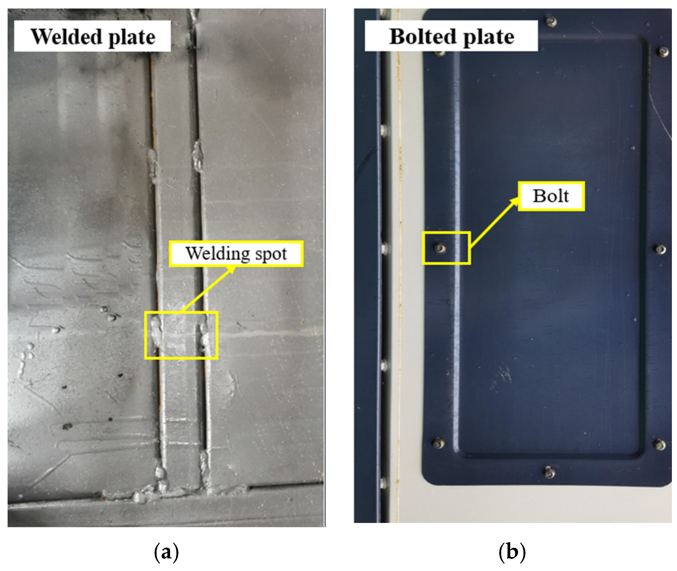
2.2. Types of Combine Shell Structures
2.3. Combine Harvester Plate and Shell Structure Modal Simulation
- (1)
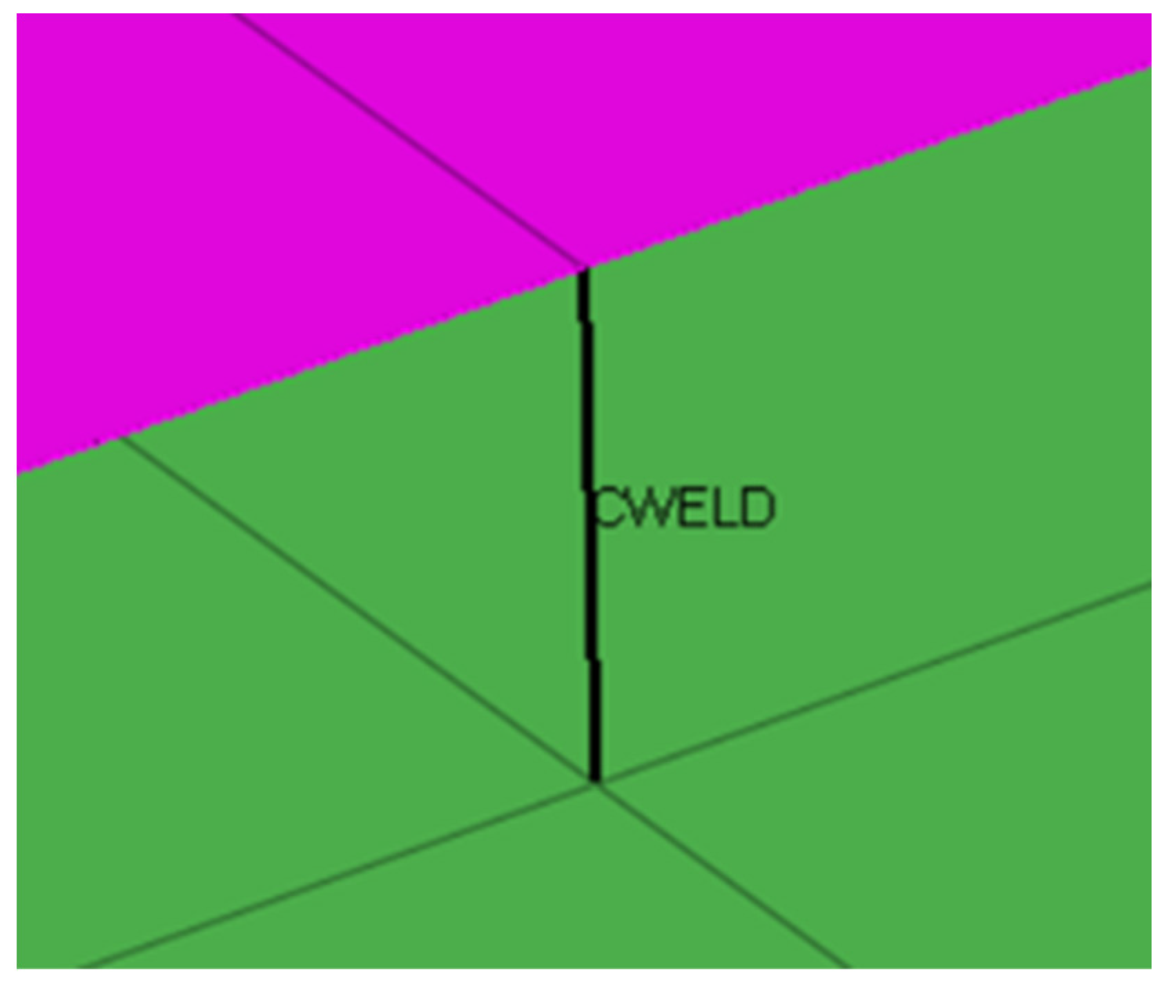
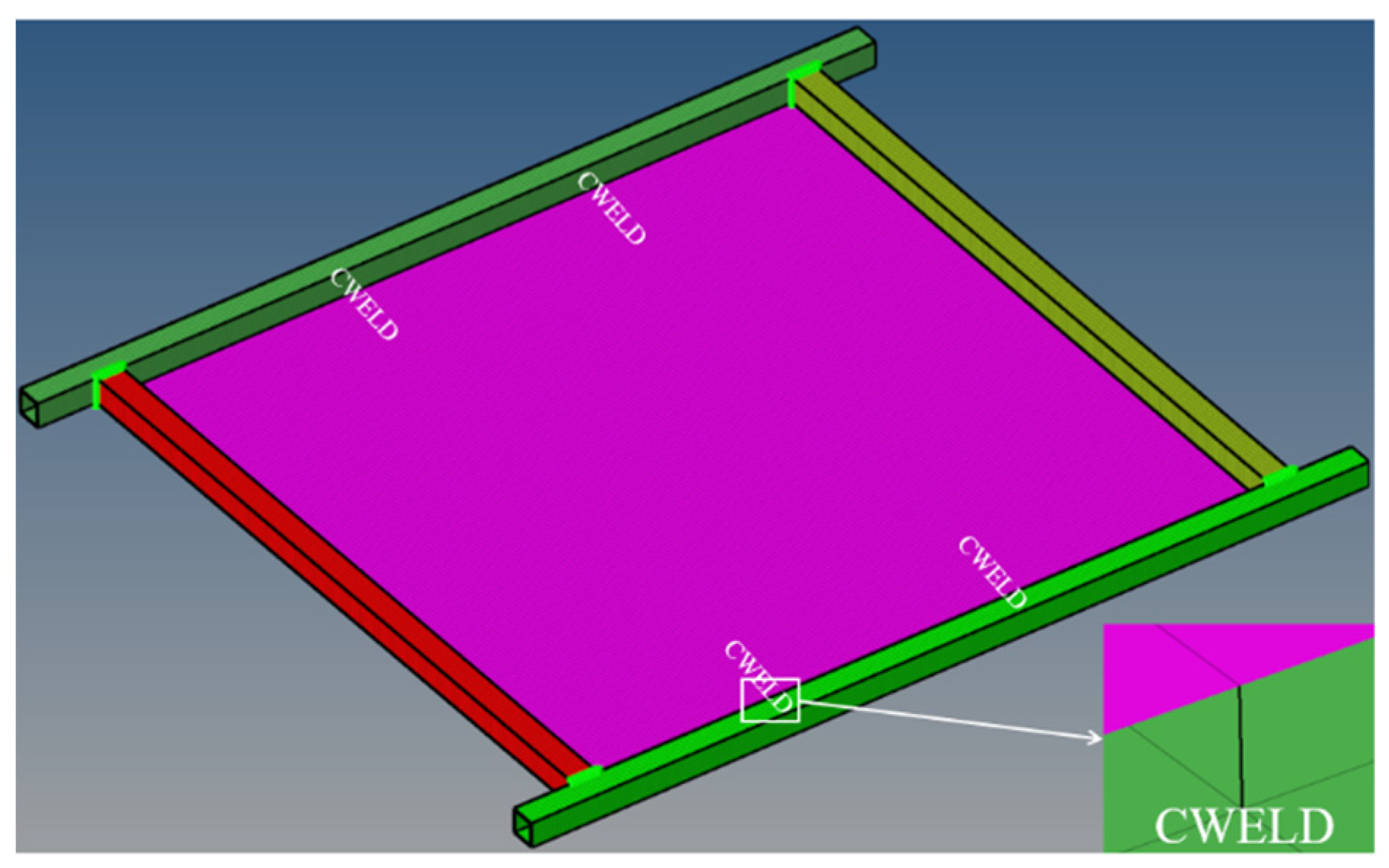
- Simulation of spot-welding unit
- (2)
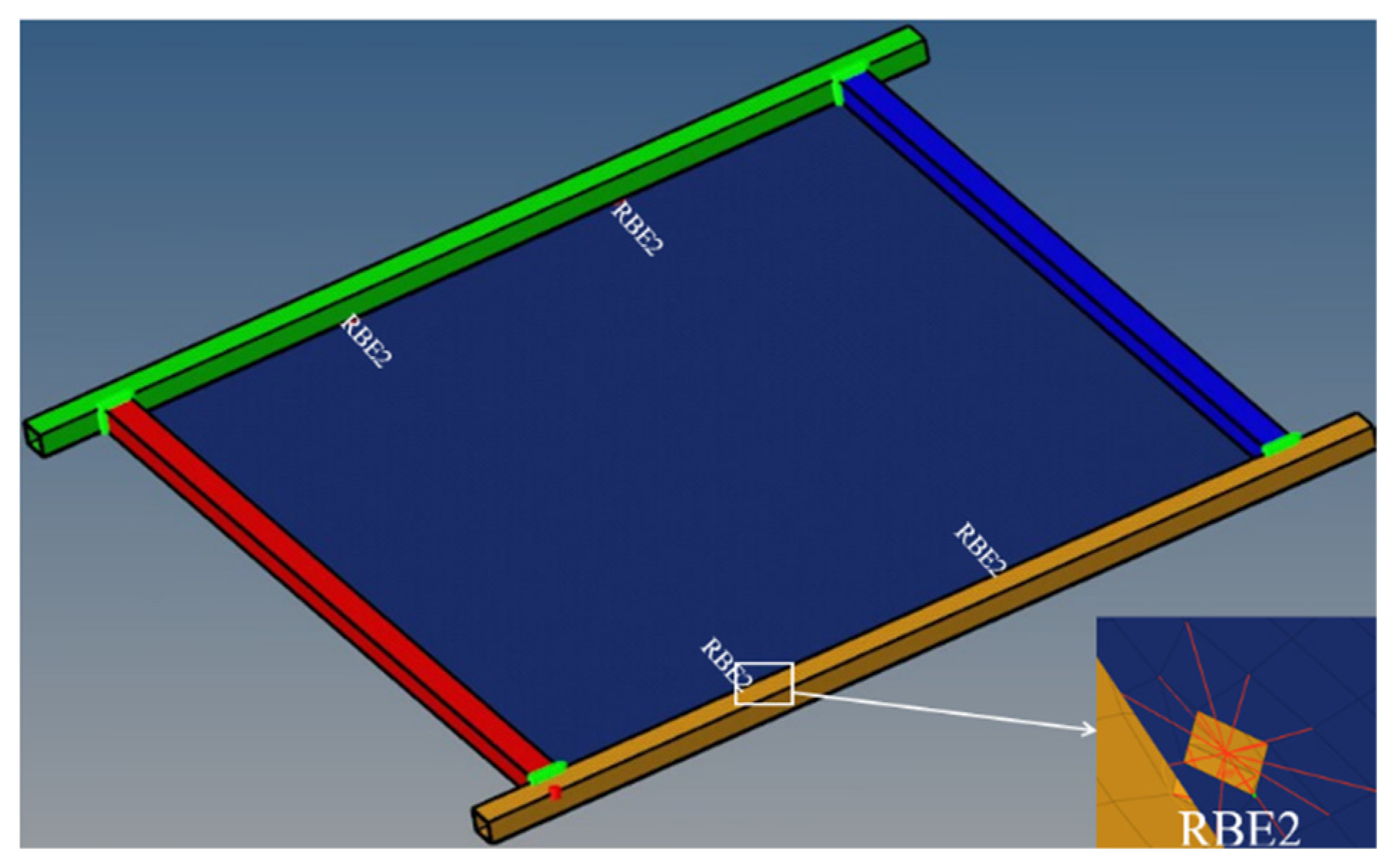
- Simulation of bolt connection
2.4. Equivalent Modeling of Plate and Shell Structures
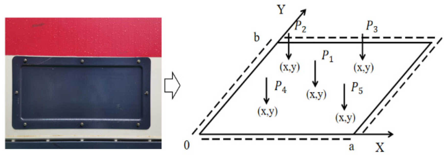
2.4.1. Dynamic Modeling of a Four-Sided Simply Supported Plate
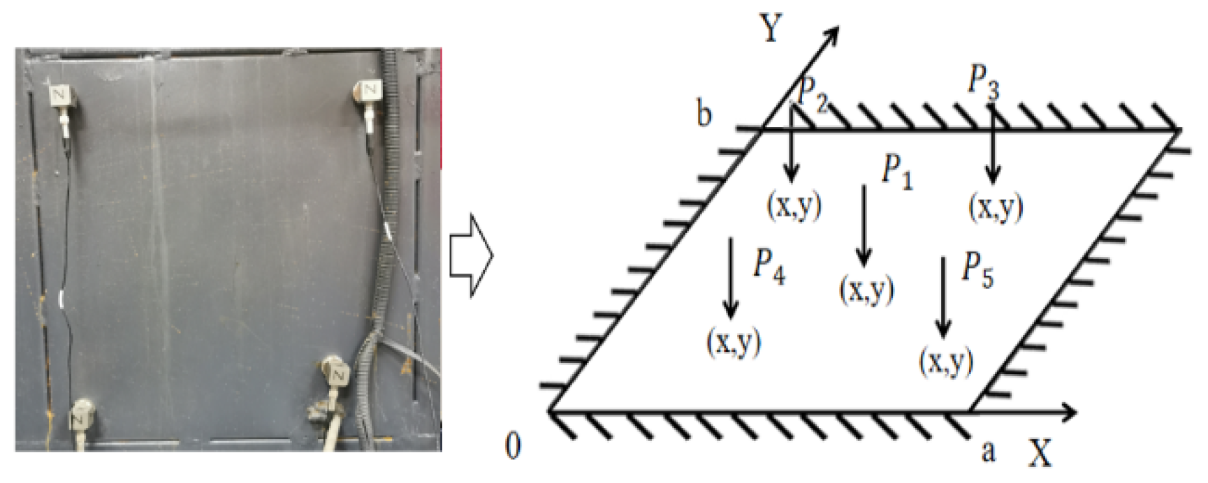
2.4.2. Dynamic Modeling of a Four-Sided Fixed-Support Plate
2.4.3. Modal Analysis of Plate and Shell with Different Connections Designed
3. Results and Discussions
3.1. Analysis of Simulation Results of Plate and Shell Structure
- (1)
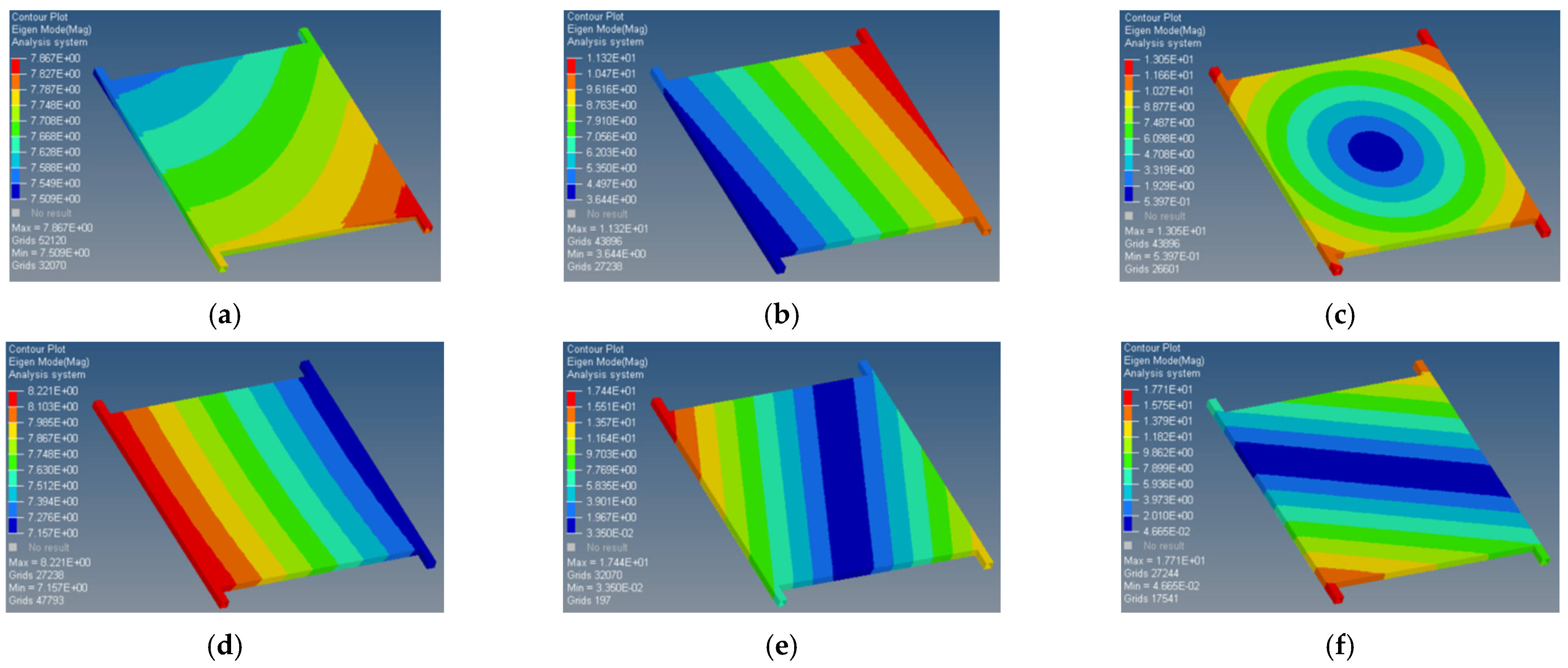
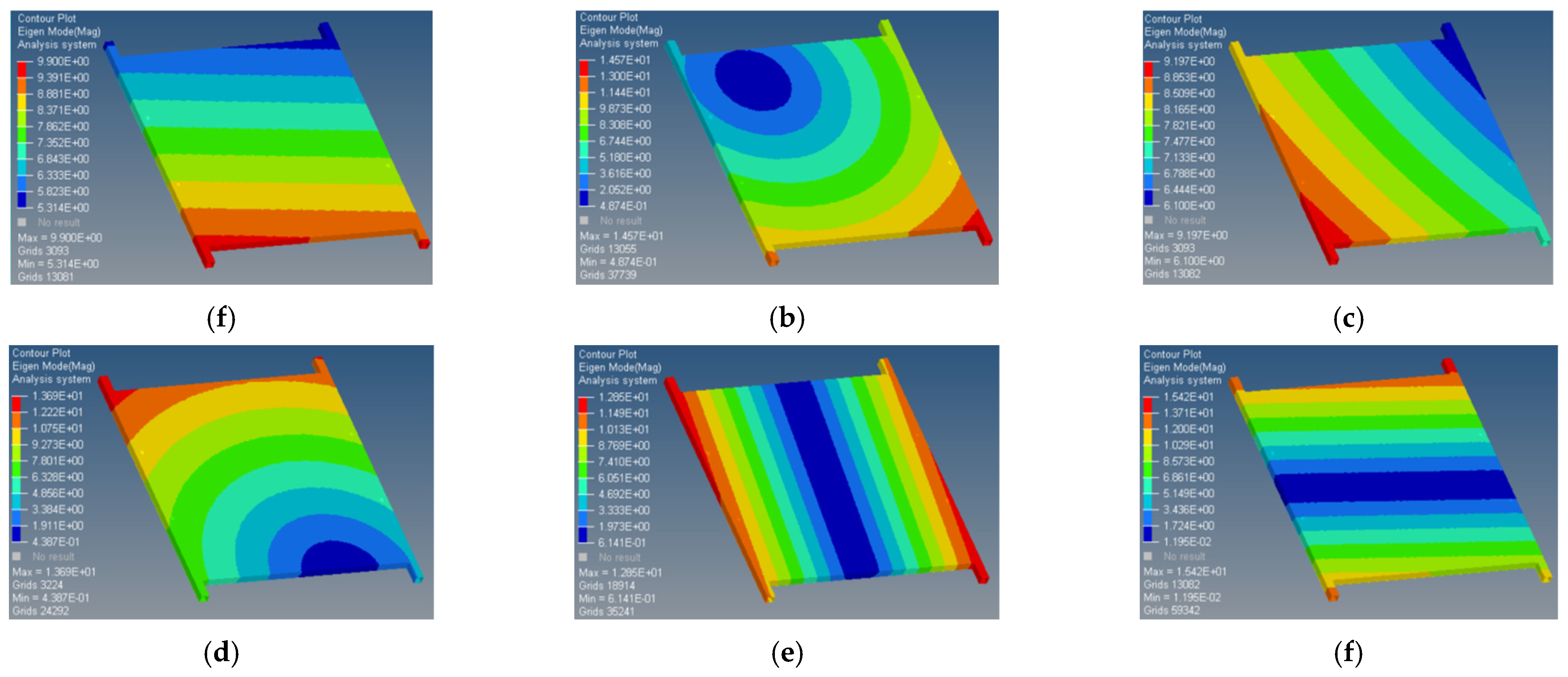
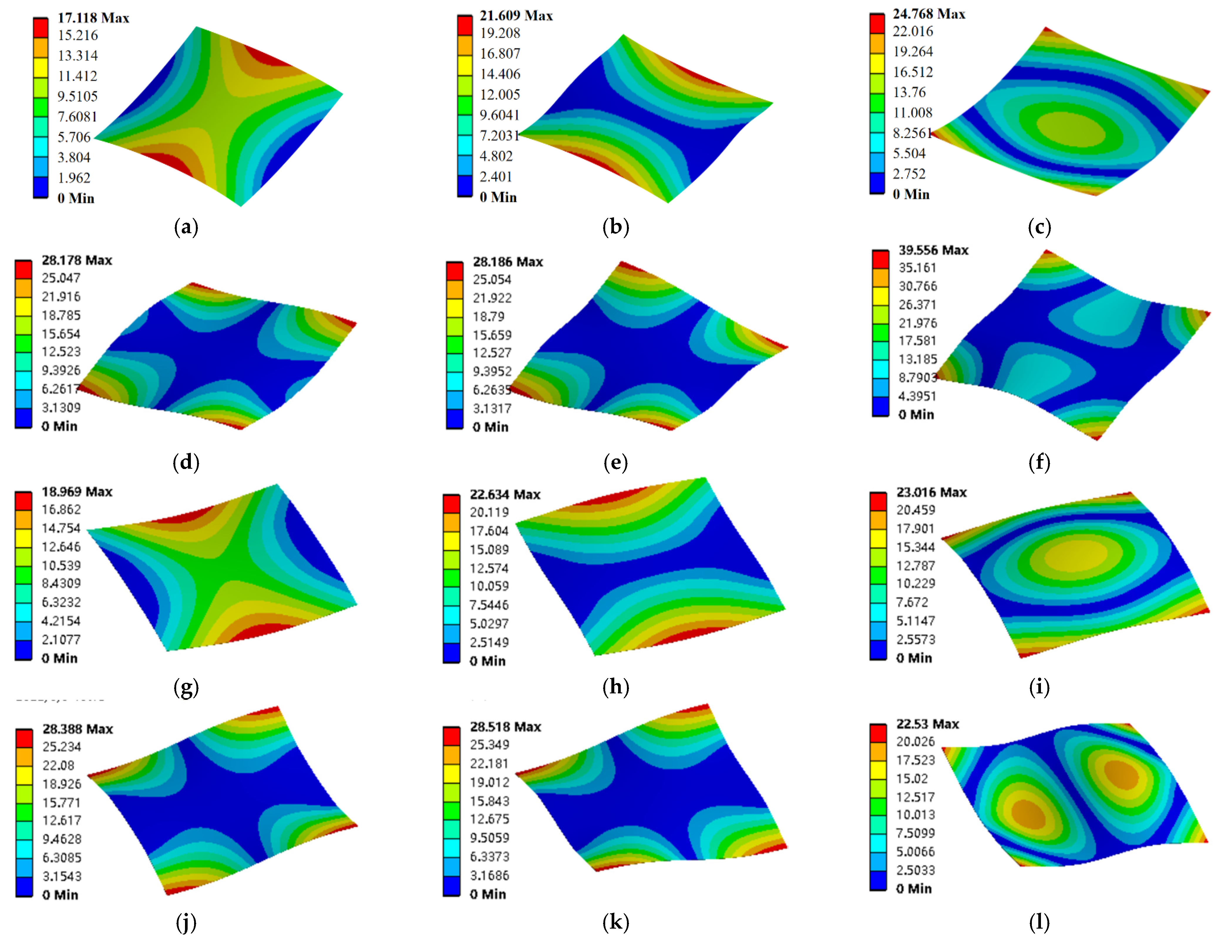
- Analysis of modal frequencies and vibration patterns
- (2)
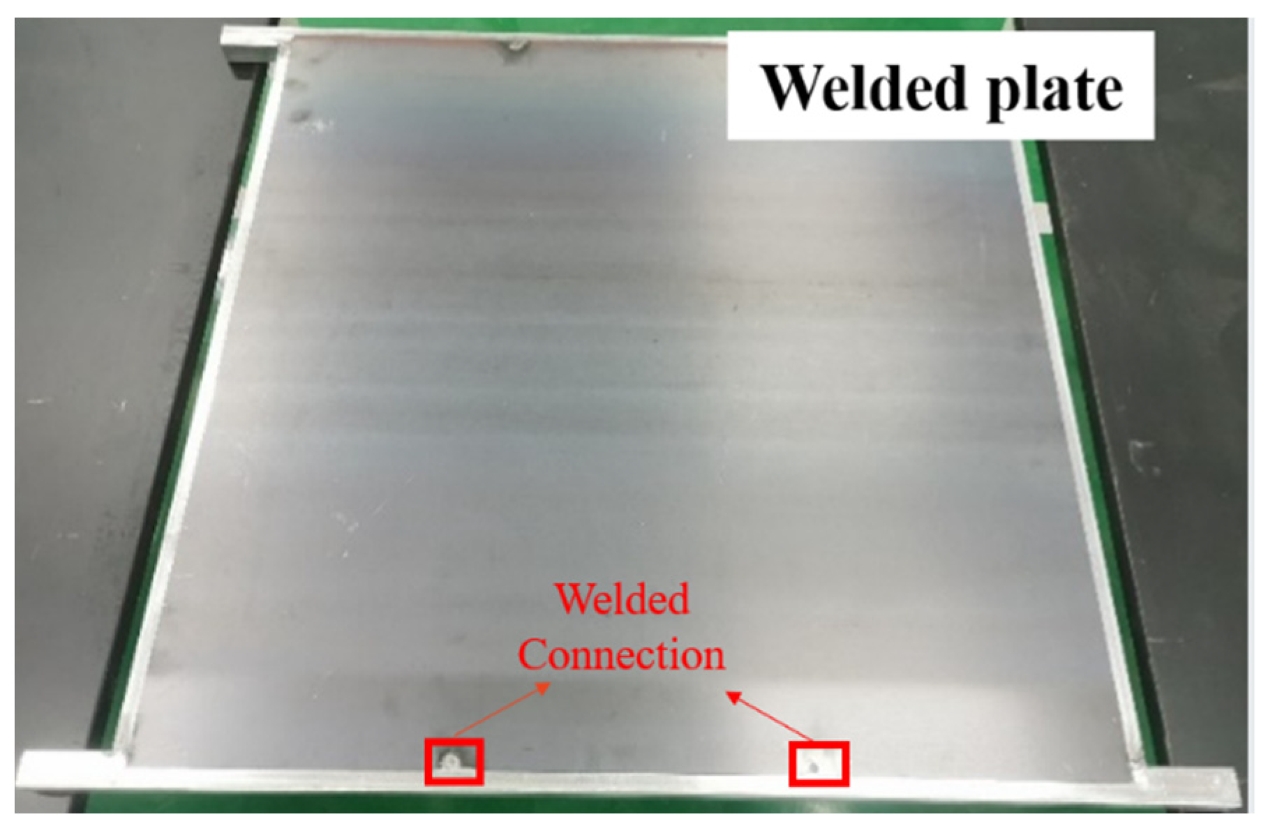
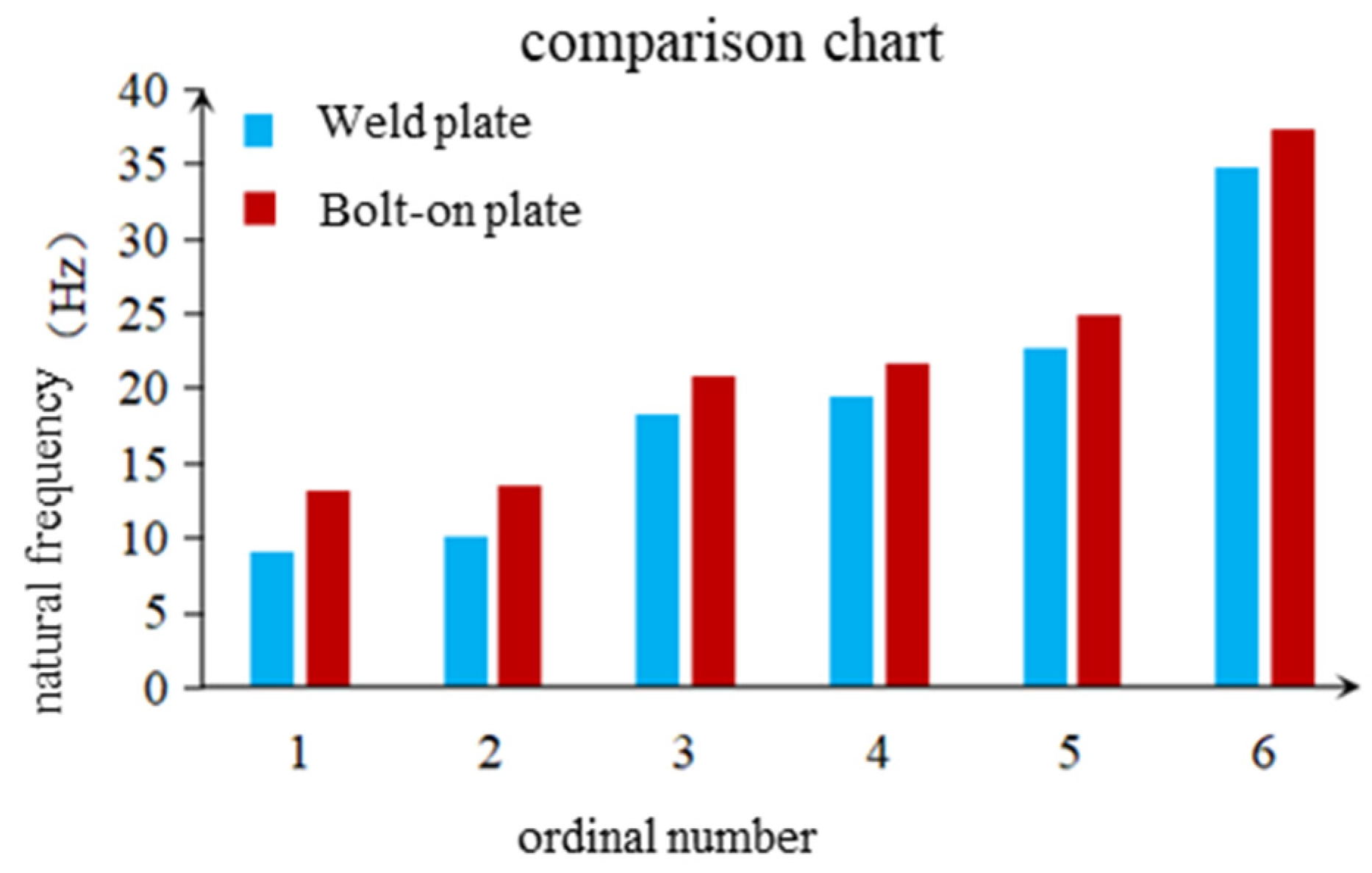
- Comparative analysis of welded and bolted plates
3.2. Validation of Test Results
- (1)
- Parametric identification of frequency response curves of received vibration signals
- (2)
- Comparison between dynamic model and simulation model.
- (1)
- Analysis of modal test data of plate and shell structure
3.3. Sections to Be Improved
- (1)
- In this paper, the forced response vibration modeling of welded and bolted plates under multi-source excitation is not well studied. In particular, the dynamic equations of the four-sided solidly supported plate under multi-point concentrated simple harmonic force need to be further investigated. In addition, the intrinsic vibration dynamic model of the simply supported plate and the solidly supported plate should be explored more deeply in order to obtain a more accurate expression of the vibration characteristics of the structure.
- (2)
- For the vibration response of the four-sided simply supported plate and the four-sided solidly supported plate under the action of multi-point concentrated simple harmonic force, the influencing factors need to be further investigated, and the influence of each structural parameter on the forced vibration of the plate and shell should be explored in depth. On this basis, the optimal design scheme of the plate and shell structure is further optimized, and a better scheme is proposed to design the plate and shell structure of the combine harvester. In order to optimize the structure of the plate on the combine harvester, the plate before and after optimization should be installed to the corresponding position on the combine harvester, and the vibration signals of the plate should be measured and compared in order to obtain more realistic data.
4. Conclusions
- (1)
- Through the comparison and analysis of the first six orders of the intrinsic vibration pattern and intrinsic frequency, it is concluded that the connection of the plate and the frame has a significant impact on the intrinsic vibration characteristics of the plate. The bolt connection makes the intrinsic vibration frequency of the plate higher than that of the welding method, but the intrinsic vibration pattern of the plate has a small impact.
- (2)
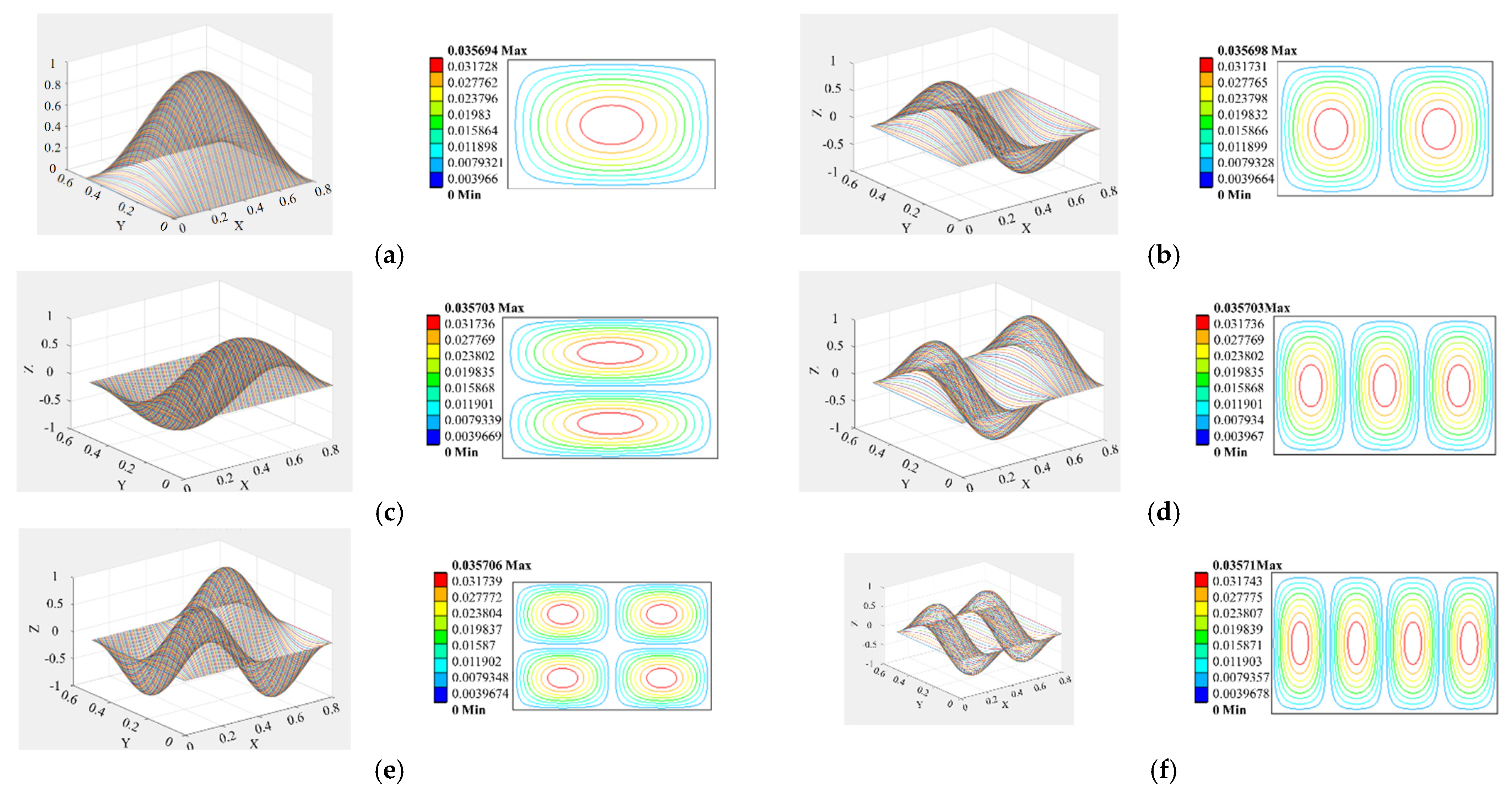
- The expressions of natural modes of the four-sided simply supported plate and four-sided fixed supported plate are obtained from the angle of analytical method. Through the kinetic equations constructed in this paper, the intrinsic shapes of the four-sided (simply supported) solidly supported plate are the same as those obtained from the simulation model. At the same time, by comparing the natural frequency obtained by simulation and the natural frequency obtained by analysis, the error of the four-sided simply supported plate model is between 0 and 0.53%, which can be considered as less than 1%. The error of the four-sided fixed support plate is between 2.14 and 2.45%, which can be judged as less than 3%.
- (3)
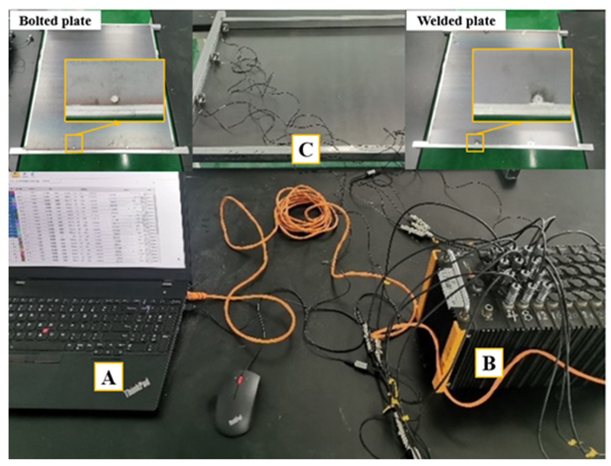
- The vibration signal acquisition method of single-point excitation and multi-point pickup is adopted, and the hammer method is used as the excitation method to verify the influence of different connection methods on the natural vibration characteristics of the plate and shell structure. After parameter identification of the frequency response curve of the received vibration signal, the accuracy of parameter identification is judged by a MAC graph.
Author Contributions
Funding
Institutional Review Board Statement
Data Availability Statement
Conflicts of Interest
References
- Akter, H.; Ali, R.; Alam, S.; Sarker, T.R.; Ahamed, S.; Saha, C.K. Estimation of economic life and feasibility of combine harvesters in Bangladesh deploying a unique web-based app. Smart Agric. Technol. 2024, 7, 100378. [Google Scholar] [CrossRef]
- Wu, S.; Wei, X. Mechanical interaction between a canopy opener and rice stalks based on the transient dynamic analysis. Biosyst. Eng. 2019, 178, 256–263. [Google Scholar] [CrossRef]
- Chen, Z.; Qin, B.; Wang, Q.; Zhong, R.; Wang, A. Vibration analysis of laminated open cylindrical shell coupled with rectangular plates. Compos. Struct. 2022, 292, 115607. [Google Scholar] [CrossRef]
- Christy, D.L.; Pillai, T.M.; Nagarajan, P. Thin plate element for applied element method. Structures 2019, 22, 1–12. [Google Scholar] [CrossRef]
- Kurec, K.; Kamieniecki, K.; Piechna, J. Influence of Different Plates Arrangements on the Car Body. Energies 2022, 15, 619. [Google Scholar] [CrossRef]
- Liu, J.; Zhao, S.; Li, N.; Faheem, M.; Zhou, T.; Cai, W.; Zhao, M.; Zhu, X.; Li, P. Development and field test of an autonomous strawberry plug seeding transplanter for use in elevated cultivation. Appl. Eng. Agric. 2019, 35, 1067–1078. [Google Scholar] [CrossRef]
- Guo, X.; Su, Z.; Wang, L. Modified Fourier Approach for Vibration Analysis of Spinning Beam with Elastic Restraints. Int. J. Struct. Stab. Dyn. 2023, 23, 2350142. [Google Scholar] [CrossRef]
- Faheem, M.; Liu, J.; Chang, G.; Abbas, I.; Xie, B.; Shan, Z.; Yang, K. Experimental Research on Grape Cluster Vibration Signals during Transportation and Placing for Harvest and Post-Harvest Handling. Agriculture 2021, 11, 902. [Google Scholar] [CrossRef]
- Khludnev, A. Non-coercive problems for Kirchhoff-Love plates with thin rigid inclusion. Z. Angew. Math. Phys. 2022, 73, 1–18. [Google Scholar] [CrossRef]
- Kim, K.; Kim, C.; An, K.; Kwak, S.; Ri, K.; Ri, K. Application of Haar wavelet discretization method for free vibration analysis of inversely coupled composite laminated shells. Int. J. Mech. Sci. 2021, 204, 106549. [Google Scholar] [CrossRef]
- Xie, K.; Xu, K.; Dong, W.; Chen, M. An analytic method for vibration analysis of non-uniformly coupled L-shaped plates with arbitrary boundary conditions. Thin-Walled Struct. 2023, 186, 110639. [Google Scholar] [CrossRef]
- Peng, Y.; Zhao, S.; Liu, J. Fused deep features-based grape varieties identification using support vector machine. Agriculture 2021, 11, 869. [Google Scholar] [CrossRef]
- Le, K. An asymptotically exact first-order shear deformation theory for functionally graded plates. Int. J. Eng. Sci. 2023, 190, 103875. [Google Scholar] [CrossRef]
- Hou, Y.; Li, Z.; Gong, J. A compound strip method based on the Mindlin plate theory for static and buckling analyses of thin-walled members with transverse stiffeners. Thin-Walled Struct. 2023, 188, 110796. [Google Scholar] [CrossRef]
- Allahkarami, F.; Tohidi, H. Axisymmetric Postbuckling of Functionally Graded Graphene Platelets Reinforced Composite Annular Plate on Nonlinear Elastic Medium in Thermal Environment. Int. J. Struct. Stab. Dyn. 2023, 23, 500347. [Google Scholar] [CrossRef]
- Oh, B.; Kim, C.; Lee, D.; Rho, J.; Moon, W. An improved analytic model for designing the polymer-composite stepped-plate transducer using the modified Mindlin plate theory. Ultrasonics 2023, 131, 106933. [Google Scholar] [CrossRef]
- Fan, J.; Ma, T.; Zhang, W.; Zhu, Y.; Wang, H. Inner dimension detection of open and buried crack in asphalt pavement based on Rayleigh wave method. Constr. Build. Mater. 2022, 328, 127003. [Google Scholar] [CrossRef]
- Xu, L.; Wei, C.; Liang, Z.; Chai, X.; Li, Y.; Liu, Q. Development of rapeseed cleaning loss monitoring system and experiments in a combine harvester. Biosystems Engineering 2019, 178, 118–130. [Google Scholar] [CrossRef]
- Li, J.; Nie, Z.; Chen, Y.; Ge, D.; Li, M. Development of Boom Posture Adjustment and Control System for Wide Spray Boom. Agriculture 2023, 13, 2162. [Google Scholar] [CrossRef]
- Cao, R.; Yuan, J. Selection Strategy of Vibration Feature Target under Centrifugal Pumps Cavitation. Appl. Sci. 2020, 10, 8190. [Google Scholar] [CrossRef]
- Liu, S. A finite element analysis procedure using simple quadrilateral plate/shell elements. Comput. Struct. 1989, 32, 937–944. [Google Scholar] [CrossRef]
- Pachas, V.S.; Paredes, A.D.; Beltran, J. Derivation of the equations of motion and boundary conditions of a thin plate via the variational method. Rev. Bras. de Ensino de Física 2022, 44, e20210387. [Google Scholar] [CrossRef]
- Lian, Y.; Chen, J.; Guan, Z.; Song, J. Development of a monitoring system for grain loss of paddy rice based on a decision tree algorithm. Int. J. Agric. Biol. Eng. 2021, 14, 224–229. [Google Scholar] [CrossRef]
- Huang, P.; Xiao, Y.; Zhang, J.; Cai, H.; Song, H. The Influence of Flow Rates on Pressure Fluctuation in the Pump Mode of Pump-Turbine with Splitter Blades. Appl. Sci. 2020, 10, 6752. [Google Scholar] [CrossRef]
- Cao, Y.; Zhang, R.; Zhang, W.; Wang, J. Vibration Characteristics Analysis of Cylindrical Shell-Plate Coupled Structure Using an Improved Fourier Series Method. Shock. Vib. 2018, 2018, 9214189. [Google Scholar] [CrossRef]
- Tang, Q.; Li, C.; She, H.; Wen, B. Analysis of frequency and mode shape of rotating-flexible disk-drum coupled structure with non-continuous connections. Int. J. Mech. Sci. 2021, 190, 106004. [Google Scholar] [CrossRef]
- Eitner, M.A.; Ahn, Y.J.; Musta, M.N.; Clemens, N.T.; Sirohi, J. Vibration of a thin panel exposed to ramp-induced shock-boundary layer interaction at Mach 2. J. Fluids Struct. 2023, 119, 103894. [Google Scholar] [CrossRef]
- Ma, Z.; Zhang, Z.; Zhang, Z.; Song, Z.; Liu, Y.; Li, Y.; Xu, L. Durable Testing and Analysis of a Cleaning Sieve Based on Vibration and Strain Signals. Agriculture 2023, 13, 2232. [Google Scholar] [CrossRef]
- Xuan, G.; Yue, J.; Wang, Y.; Wang, D. An edge-based smoothed finite element method combined with Newmark method for time domain acoustic wave scattering problem. Eng. Anal. Bound. Elem. 2024, 158, 182–198. [Google Scholar] [CrossRef]


| Material | Modulus of Elasticity E(MPa) | ||
|---|---|---|---|
| Plain carbon steel (45 steel) | 0.3 | ||
| Electric welding material | 0 | 0.3 |
| No. | Equipment Name | Model | Manufacturer | Main Parameters |
|---|---|---|---|---|
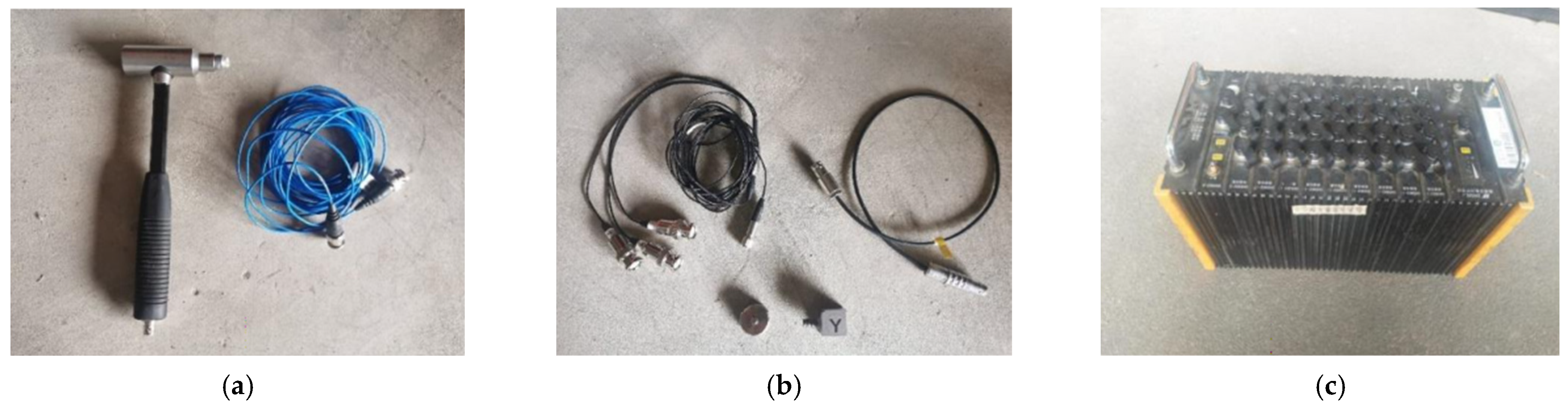
| 1 | Exciting force hammer (nylon hammer head) | LC02 | PCB | Sensitivity: 10 mV/1 bf; Range: ±500 1bf pk |
| 2 | Force transducer | 3A102 | PCB | Sensitivity: 4.512 pC/N Range: ±500 N |
| 3 | Piezoelectric acceleration sensor | 1A312E | PCB | Sensitivity: 100 mV/g Range: ±500 g |
| 4 | Signal acquisition instrument | DH5902 | DongHua Test | Number of channels: 36 Sampling bandwidth: 16,100 kHz |
| Object of Analysis | Order | Frequency/Hz | Mode Shape |
|---|---|---|---|
| Bolt connection plate | 1 | 4.24 × 10⁻³ | Overall lower left corner of the front and rear vibration |
| 2 | 4.53 × 10⁻³ | Overall front–back vibration | |
| 3 | 4.56 × 10⁻³ | Overall up and down translation | |
| 4 | 4.65 × 10⁻³ | Overall left–right translation | |
| 5 | 5.05 × 10⁻³ | Overall left–right–front–right torsion | |
| 6 | 5.37 × 10⁻³ | Overall up and down/back and forth twisting | |
| Weld plate | 1 | 4.28 × 10⁻³ | Overall left–right translation |
| 2 | 4.52 × 10⁻³ | Integral front–back translation | |
| 3 | 4.63 × 10⁻³ | Overall first-order torsional mode | |
| 4 | 4.90 × 10⁻³ | Overall up and down translation | |
| 5 | 5.63 × 10⁻³ | Overall left–right–front–right torsion | |
| 6 | 5.74 × 10⁻³ | Overall up and down/back and forth torsion |
| Object of Analysis Order | Order | Constrained Mode Frequency/Hz | Free Mode Frequency/Hz |
|---|---|---|---|
| Welded plate | 1 | 6.3257 | 9.10 |
| 2 | 7.9732 | 10.13 | |
| 3 | 17.06 | 18.32 | |
| 4 | 19.028 | 19.53 | |
| 5 | 20.33 | 22.69 | |
| 6 | 33.898 | 34.80 | |
| Bolt-on plate | 1 | 9.4655 | 13.21 |
| 2 | 9.9113 | 13.55 | |
| 3 | 19.602 | 20.87 | |
| 4 | 22.499 | 21.75 | |
| 5 | 22.825 | 24.91 | |
| 6 | 35.393 | 37.31 |
| No. | Parameter | Value |
|---|---|---|
| 1 | Size (length a, width b) | a b = 0.8 m 0.5 m |
| 2 | Thickness (h) | H = 0.001 m |
| 3 | Mass density () | = 7850 kg/ |
| 4 | Modulus of elasticity (E) | E = 2 × Pa |
| 5 | Poisson’s ratio () | = 0.3 |
| Modal Order | Simulated Intrinsic Modal Order | Analytical Intrinsic Frequency | Error |
|---|---|---|---|
| 1 | 13.346 | 13.346 | 0% |
| 2 | 24.593 | 24.593 | 0% |
| 3 | 42.153 | 42.138 | 0.36% |
| 4 | 43.347 | 43.338 | 0.21% |
| 5 | 53.396 | 53.385 | 0.21% |
| 6 | 69.617 | 69.580 | 0.53% |
| Modal Order | Simulated Intrinsic Frequency | Analytical Intrinsic Frequency | Error |
|---|---|---|---|
| 1 | 25.564 | 26.1222 | 2.18% |
| 2 | 37.79 | 38.6782 | 2.35% |
| 3 | 58.736 | 60.0771 | 2.28% |
| 4 | 63.744 | 65.1227 | 2.16% |
| 5 | 75.21 | 77.0536 | 2.45% |
| 6 | 87.905 | 89.7852 | 2.14% |
| Object of Analysis | Order | Intrinsic Frequency/Hz | Intrinsic Vibration Pattern |
|---|---|---|---|
| Welded plate | 1 | 61.608 | 1st-order bending |
| 2 | 81.677 | First-order torsion | |
| 3 | 106.436 | Second-order bending | |
| 4 | 125.665 | Second-order torsion | |
| 5 | 138.327 | Third-order torsion | |
| 6 | 154.437 | Fourth-order torsion | |
| Bolted plate | 1 | 73.294 | 1st-order bending |
| 2 | 79.551 | First-order twist | |
| 3 | 103.795 | Second-order bending | |
| 4 | 127.225 | Second-order twist | |
| 5 | 155.841 | Third-order torsion | |
| 6 | 176.777 | Fourth-order torsion |
Disclaimer/Publisher’s Note: The statements, opinions and data contained in all publications are solely those of the individual author(s) and contributor(s) and not of MDPI and/or the editor(s). MDPI and/or the editor(s) disclaim responsibility for any injury to people or property resulting from any ideas, methods, instructions or products referred to in the content. |
© 2024 by the authors. Licensee MDPI, Basel, Switzerland. This article is an open access article distributed under the terms and conditions of the Creative Commons Attribution (CC BY) license (https://creativecommons.org/licenses/by/4.0/).
Share and Cite
Ding, Z.; Tang, Z.; Zhang, B.; Ding, Z. Vibration Response of Metal Plate and Shell Structure under Multi-Source Excitation with Welding and Bolt Connection. Agriculture 2024, 14, 816. https://doi.org/10.3390/agriculture14060816
Ding Z, Tang Z, Zhang B, Ding Z. Vibration Response of Metal Plate and Shell Structure under Multi-Source Excitation with Welding and Bolt Connection. Agriculture. 2024; 14(6):816. https://doi.org/10.3390/agriculture14060816
Chicago/Turabian StyleDing, Zhexuan, Zhong Tang, Ben Zhang, and Zhao Ding. 2024. "Vibration Response of Metal Plate and Shell Structure under Multi-Source Excitation with Welding and Bolt Connection" Agriculture 14, no. 6: 816. https://doi.org/10.3390/agriculture14060816