Article

The Simulation and Parameter Optimization of the Hole-Forming Process of a Duckbilled Hole-Forming Device

1
College of Mechanical and Electrical Engineering, Shihezi University, Shihezi 832003, China
2
Key Laboratory of Northwest Agricultural Equipment, Ministry of Agriculture and Rural Affairs, Shihezi 832000, China
3
Xinjiang Production and Construction Corps Key Laboratory of Modern Agricultural Machinery, Shihezi 832000, China
*
Author to whom correspondence should be addressed.
Agriculture 2024, 14(6), 843; https://doi.org/10.3390/agriculture14060843
Submission received: 30 March 2024 / Revised: 16 May 2024 / Accepted: 23 May 2024 / Published: 28 May 2024
(This article belongs to the Section Agricultural Technology)

Abstract

:
This paper addresses the hole-forming process of a duckbilled hole-forming device. Based on a coupled simulation using the multi-body dynamics software RecurDyn and the discrete element software EDEM, the hole-forming mechanism of a duckbilled hole-forming device and the influence of control parameters on the hole-forming performance of the hole-forming device were studied. In this paper, we analyze the direction and speed of soil particles transported under soil disturbance by a hole-forming device through the simulation and study of the hole-forming mechanism of the hole-forming device. By controlling parameters such as the traction angle, forward speed, and mass of the hole-forming device, the influence of the control parameters on the hole-forming trajectory of the duckbilled hole-forming device was investigated. Orthogonal tests determined the optimal combination of control parameters. The results show that the hole-forming process of the hole-forming device mainly comprises squeezing and shearing the soil to form holes, and the hole-forming performance of the hole-forming device was optimal when the traction angle was 17.3°, the forward speed was 1.11 m/s, and the mass of the hole-forming device was 17.9 kg.

1. Preface

Xinjiang is a vital cotton-planting base in China, and a large amount of cotton is planted and harvested annually. Sowing is one of the critical aspects of determining yield in cotton planting. Traditional manual seeding is time-consuming, labor-intensive, and inefficient, and it cannot meet the needs of large-scale cotton planting. Mechanical seeding can significantly improve the efficiency of cotton planting, reduce the grower’s physical labor, and enable accurate control over the depth of planting, row spacing, and the number of seeds [1,2,3]. Cotton planting in Xinjiang is mainly dominated by hole sowing on the membrane, which has the advantages of heat preservation, moisture retention, and reducing weed growth [4,5,6], which are new requirements for seeding machinery.
In order to improve the performance of hole-forming devices, relevant scholars at home and abroad have researched hole-forming devices through analyses of the hole-forming process, structural optimization, and interactions with soil. Concerning motion analysis of the hole-forming process of hole-forming devices, Quan et al. [7] took different shapes and different hole-forming methods (soil extraction and extrusion) as their research objects, and their results showed that the hole-forming process of soil extraction was better than the hole-forming process of extrusion; the method had higher requirements for the mechanical structure of hole-forming devices, and the holes were quickly backfilled in soft soil due to the backflow of soil particles. Zhou et al. [8,9] took different slip rates, forward speeds, and depths of entry as their objects of study, and their results showed that the slip rate was 11%, the forward speed of the machine was 0.5 m/s, and the depth of penetration of the hole-forming device was 0.03 m. The hole-forming device had a minor slip and was less likely to produce phenomena such as picking and tearing of the film. In terms of structural optimization, Hou et al. [10] designed a side-opening, slip-cutting, film-breaking precision seeding monobloc to address the problems of the considerable size and irregular shape of film holes and poor seeding quality when sowing in mulching film, which would significantly reduce the seeding efficiency of the hole-forming device. Liao et al. [11] examined existing sowing methods for the film of hole-punching devices in the actual operation of the process regarding membrane hole size, irregularly shaped membrane hole sticking, and other issues. Based on the principle of slip cutting, they designed a rolling film-cutting and punching device to determine the structural parameters of the punching device and its profiling mechanism, establish a kinematic model of the punching device, and analyze and determine the main factors affecting the length of the membrane holes and its range of values [11]. In terms of soil interaction, Bao et al. [12] used the discrete element method (DEM) to analyze the tillage process of a deep pine shovel to select the model with the best drag-reduction effect. They explored the drag reduction mechanism of a biomimetic prismatic deep pine shovel from macroscopic and microscopic perspectives. Macroscopically, the shovel and soil model were used as research objects to compare the horizontal plowing resistance and soil force; microscopically, the horizontal and vertical soil particle layers were intercepted, and the arching angle and a velocity trajectory cloud map of the particle layer were investigated. Yeon-Soo Kim developed a comprehensive geotechnical soil–mechanical coupled model based on coupling of the discrete element method (DEM) and multi-body dynamics (MBD) to predict traction forces during plowing, by considering the target tillage depth, which reflects the distribution of soil properties with the change in soil depth, the DEM soil foundation bed was simulated [13]. Regarding soil disturbance, Aili Hasimu and Zhao et al. [14,15,16] studied the soil disturbance mainly in terms of the entry earth resistance of the hole-forming device and the transport speed and trajectory of the soil particles.
Scholars at home and abroad mainly study transplanting machines and soil tillage. There are few studies on the influence of the hole-forming trajectory and the parameters of the hole-forming device, giving the research presented in this paper specific value.

2. Analysis of the Hole-Forming Device Structure and Hole-Forming Process

2.1. The Hole-Forming Device Structure

A duckbilled hole-forming device is an essential component of film sowing, and its working performance directly affects sowing quality. A duckbilled hole-forming device is composed of a hole-forming mechanism (moving duckbill, fixed duckbill, duckbill hinge, and spring), belt, dividing grid, seed baffle, chock, pressure plate, dynamic disk, arc-shaped seed blocking ring, and axis, and its structure is shown in Figure 1. This duckbilled hole-forming device consists of 15 hole-forming mechanisms and has an individual spacing of 85–100 mm, and a planting depth of 23–28 mm [17,18].

2.2. Analysis of the Motion Process of the Hole-Forming Device

The movement process of a duckbilled hole-forming device during operation is shown in Figure 2, where V is the forward speed, m/s; R is the radius of the hole-forming device, mm; Rr is the radius of the apex of the fixed duckbill, mm; α1 is the angle between the fixed duckbill AB and OA, °; α2 is the angle between the moving duckbill AC and OA, °; H is the hole sowing depth, mm; Ψ is the duckbill movement angle, °. R0 is the rolling radius of the hole-forming device, r = R/(1 − µ), mm; and μ is the slip coefficient.

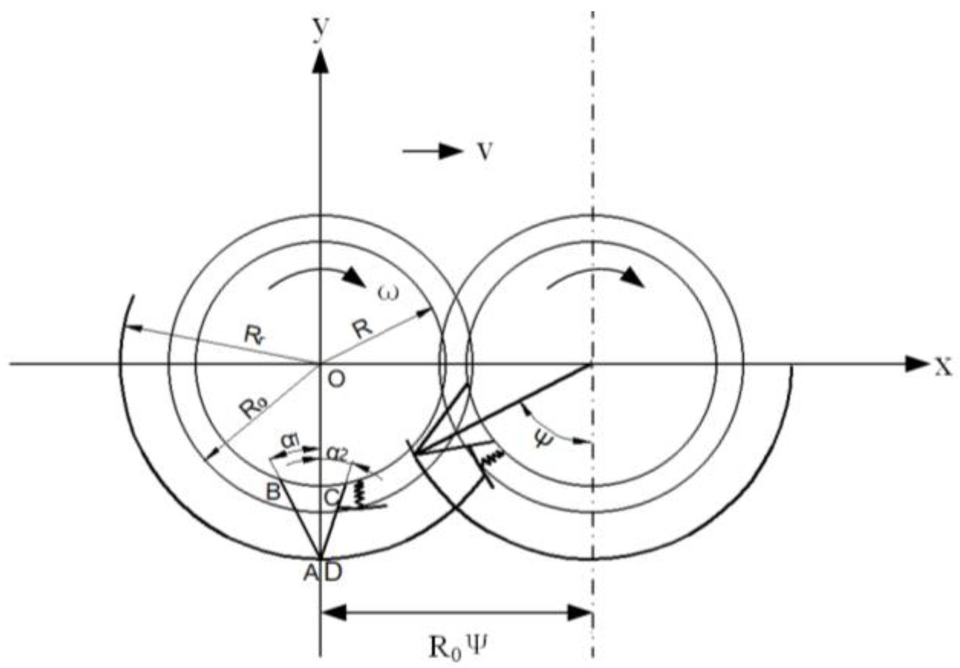
2.2.1. Analysis of Duckbill Motion Trajectory

The motion equation of the duckbill is as follows:
The equation of motion for the fixed duckbill is
x = R 0 Ψ r sin ( Ψ + φ 1 ) y = R r r cos ( Ψ + φ 1 )
The equation of motion before the opening of the moving duckbill is
x = R 0 Ψ r sin ( Ψ + φ 2 ) y = R r r cos ( Ψ + φ 2 )
The equation of motion for the points after the opening of the moving duckbill is
x = R 0 Ψ r sin ( Ψ + φ 2 ) y = R r r cos ( Ψ + φ 2 )
The equation of motion of the points on the face of the moving duckbill during its opening is
x = x c + r sin ( α 1 + α 2 θ ) = R 0 Ψ R c sin ( Ψ φ c ) + r sin ( α 1 + α 2 θ ) y = y c r sin ( α 1 + α 2 θ ) = R r R c cos ( Ψ φ c ) r cos ( α 1 + α 2 θ )
In the formula, φ1 is the central angle of any point on the fixed duckbill, °; φ2 is the center angle of the moving duckbill at one point before it opens, °; φ2′ is the center angle of the movable duckbill at any point after opening, °; θ is the angle of rotation of the moving duckbill around the point C of the pin, °; r is the radius of any point of the hole-forming device, mm; and r′ is the radius of rotation from any point on the movable duckbill to point C, mm.

2.2.2. Soil Hole Contour Analysis

Soil holes are formed by the shearing and squeezing action of the duckbill on the soil. The role of the external surface of the fixed duckbill is as follows: the upper left contour (a–b section of Figure 3) and the lower right contour (d–e section of Figure 3) of the soil hole are formed during the soil piercing process, and the lower left contour of the soil hole is formed during the unearthing process (b–c section of Figure 3). The role of the moving duckbill is as follows: during the opening of the moving duckbill, the lower contour of the hole is formed (c–d section of Figure 3), and the soil is squeezed at the later stage of the unearth and continues until the end of the unearth process, forming the upper right contour of the soil hole (e–f section of Figure 3).
From the trajectory of the hole-forming device and the process of hole-forming, it can be seen that the soil hole contour is composed of five curves, namely a–b, b–c, c–d, d–e, and e–f in Figure 3. The soil hole point in the diagram is taken as the coordinate origin O, and the rectangular coordinate system is established. The b–c and d–e segments are the motion trajectories of the tip point A of the fixed duckbill. Substituting r = Rh into Equation (1), the parametric equations of the b–c and d–e segments can be obtained as follows:
x = R 0 Ψ R r sin ( Ψ + φ 1 ) y = R r R r cos ( Ψ + φ 1 )
The c–d segment is the contour formed during the opening process of the moving duckbill tip D. Substituting r = rd′ into Equation (4), the parametric equations of the c–d segments can be obtained as follows:
x = R 0 Ψ R c sin ( Ψ φ c ) + r d sin ( α 1 + α 2 θ ) y = R h R c cos ( Ψ φ c ) + r d cos ( α 1 + α 2 θ )
In the formula, Rc is the radius of point C of the center of rotation of the moving duckbill; r d is the radius of the end point of the moving duckbill from point C of the pin;
The e–f segment is formed by extruding the outer surface CD of the moving duckbill during the unearthing process. The parameter equation is
x = R 0 Ψ R 0 sin ( θ + α + λ ) R r sin ( α + λ ) cos ( θ + α + λ ) y = R r R 0 + R 0 sin ( θ + α + λ ) R r sin ( α + λ ) sin ( θ + α + λ )
The a–b section is the trajectory line formed by AB on the outer surface of the fixed duckbill during the process of soil piercing, and its parameter equation is
x = R 0 Ψ R 0 sin ( θ + λ ) R r sin λ cos ( θ + λ ) y = R r R 0 + R 0 sin ( θ + λ ) R r sin λ sin ( θ + λ )

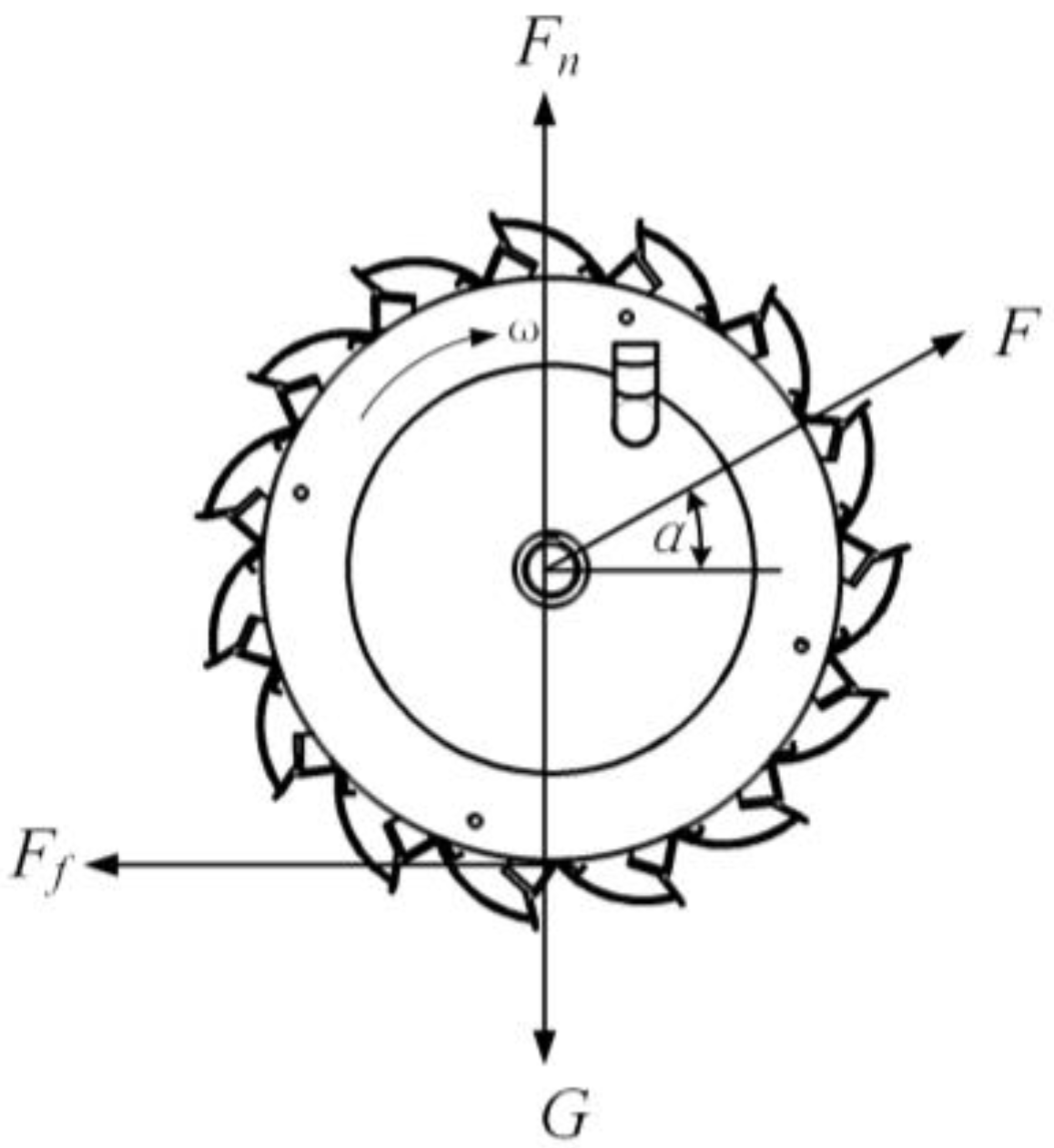
2.2.3. Dynamic Analysis of the Hole-Forming Device

The traction machinery mainly drives the movement of the hole-forming device, and the different traction angles affect the trajectory of the duckbill of the hole-forming device. The hole-forming device rolls on the soil when the whole machine moves forward. The forces on the hole-forming device can be simplified as gravity, friction, support between the hole-forming device and the soil, and traction. The forces on the hole-forming device are shown in Figure 4.
The forces in the horizontal and vertical directions are analyzed:
F cos α = F f F n + F sin α = G F f = μ F n
In the formula, G is the gravitational force of the hole-forming device itself; Fn is the support force of the soil on the hole-forming device; F is the traction force of the hole-forming device; Ff is the friction force of the ground on the hole-forming device; and α is the angle between the traction force and the direction of advance. It is obtained according to Equation (9):
F = μ G cos α + μ sin α
F n = G cos α cos α + μ sin α
From Equation (10), the traction force F increases with the increase in α after the hole-forming device reaches equilibrium. From Equation (11), the support force Fn decreases as α increases. As α increases, the traction force F increases, and the support force Fn decreases.

3. Simulation Analysis of Hole-Forming of the Hole-Forming Device

3.1. Multi-Body Dynamics Modeling

To ensure the accuracy of the simulation results, the hole-forming device was modelled in a 1:1 scale using Solidworks 2021 software. We save in the s_t format imported into RecurDyn V9R5 software; to reduce the number of operations, the hole-forming device structure parts that do not affect the simulation results are simplified, and the motion is added to the parts, as shown in Table 1.

3.2. Soil Discrete Element Modelling

The discrete element method is a numerical computational method commonly used to study the problems of particle accumulation, particle flow, collision process, particle deformation, etc. By simulating the particle system, the discrete element method can predict and analyze the mechanical properties, deformation behaviors, particle gap changes, and other information of the particle system [19]. It can simulate the interaction of the hole-forming device with the soil in reality more accurately. The EDEM software can accurately obtain the hole-forming device forces and the disturbance to the soil during the rolling process. In the modeling, in order to make the model close to reality, the soil particles were selected as spherical particles with a radius of 3 mm [20,21], and the particle contact model was selected as Hertz–Mindlin with bonding; the modeling parameters [22,23,24,25] are shown in Table 2.

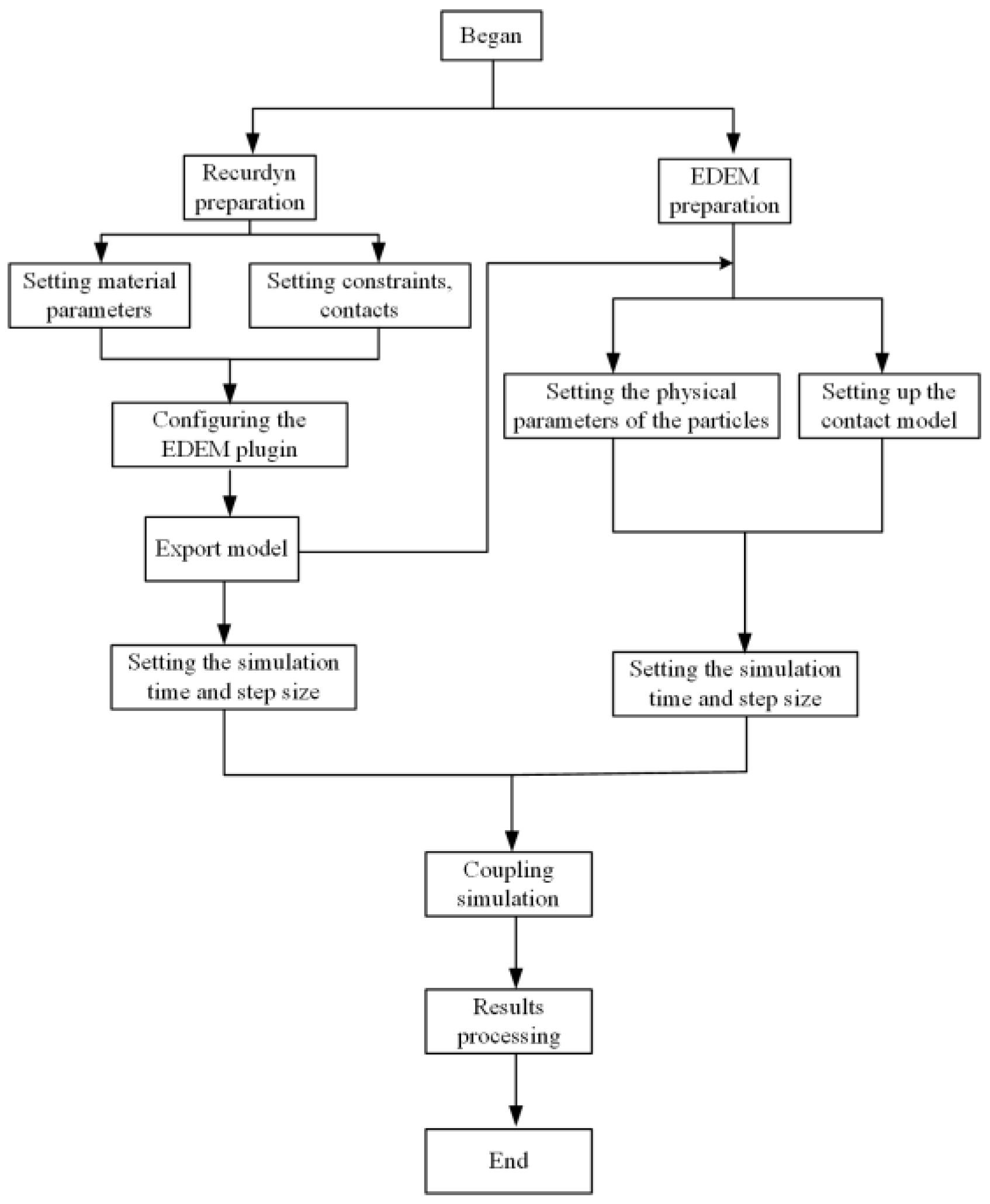
3.3. Coupling Simulation

3.3.1. Coupling Simulation of a Single Duckbill

During the rolling process, the hole-forming device interacts with the soil, causing the velocity of the soil particles to change, and the velocity size of soil particles is a direct response to the degree of disturbance of the soil during the hole-forming process. In order to visualize the disturbance of the duckbill on the soil particles, a duckbill model was imported into the EDEM 2022 software during the coupling process [15,26,27,28]. The simulation time is set to 1 s, the step length is 2 × 10⁻⁴ s in the EDEM software, and the simulation time is set to 1 s. The step length is set to 500 in the RecurDyn V9R5 software; the traction angle is 20°, the mass of the hole-forming device is 17 kg, the forward speed of the hole-forming device is 1.11 m/s as the parameter, and the specific process is shown in Figure 5.

3.3.2. Integral Simulation of the Hole-Forming Device

In order to investigate the influence of different parameters on the hole-forming trajectory of the hole-forming device, the forward speed, traction angle, and mass of the hole-forming device were used as control parameters, and the hole-forming process of the hole-forming device was simulated in a coupled manner. The simplified burrower model is imported into EDEM software, the simulation time is set to 1 s, and the time step is 2 × 10⁻⁴ s in EDEM software. The simulation time is set to 1 s, and the step is 500 in RecurDyn software, and the hole-forming process of the hole-forming device is coupled and simulated through the coupling interface.

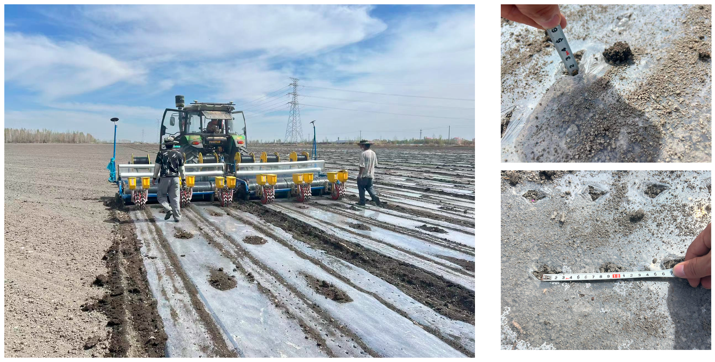
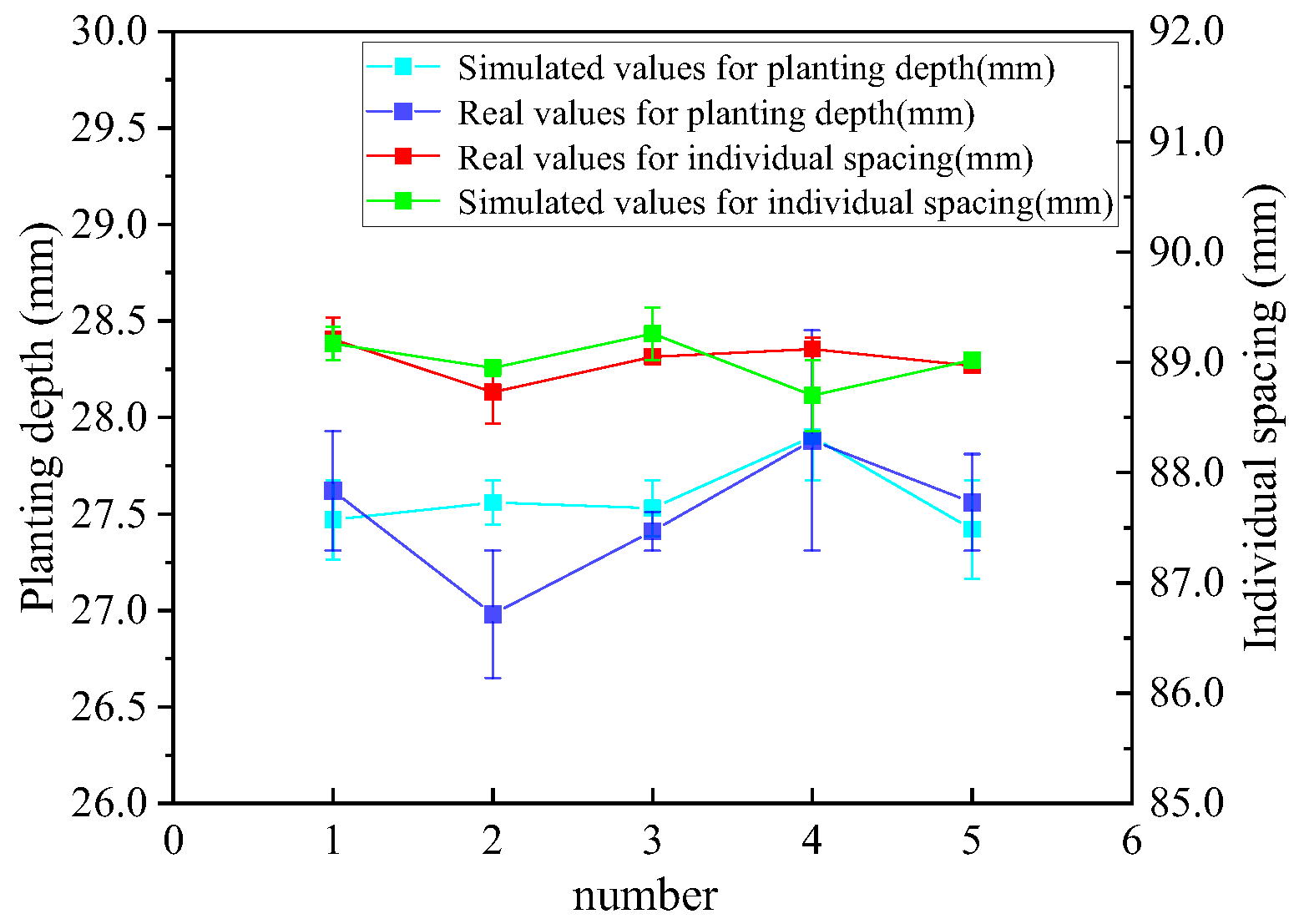
3.4. Model Validation

The research team conducted a series of field tests to verify the accuracy and reliability of the simulation model in practical application. The critical operating parameters were strictly set as follows: traction angle of 17.3°, forward speed of 1.11 m/s, and mass of the hole-forming device of 17.9 kg. The test site was selected in a test field belonging to Shihezi University in Shihezi City, Xinjiang Uygur Autonomous Region, where the typical soil and climatic conditions provided an ideal natural environment for the tests.
During the trial’s preparation phase, the research team carried out ground preparation work on the trial field to ensure that the surface was flat and free of obstacles and to eliminate factors that might impact the trial’s results. The flatness of the ground is crucial for the stable operation of the traction equipment and the hole-former, which ensures the uniformity of the operation and the mass of the hole-former.
For the accuracy of the measurement results of field trials, five groups of tests were conducted to reduce the impact of random error and systematic error. The experimental field was divided into several areas, each measured in a group. Each group of tests measured the sowing depth and plant spacing. Each group of tests measured individual spacing and planting depth. The average of the measurement results of each test index was taken as the result of each group of tests. Figure 6 shows the field trials.
The measured planting depth, individual spacing simulation value, and actual value are shown in Table 3.
As can be seen from Figure 7, in the hole-forming process of the hole-forming device, the maximum error between the simulation value of individual spacing and the test value is 1.15%, and the average relative error is about 0.48%; the maximum relative error between the simulation value of the planting depth and the test value is 2.89%, and the average relative error is about 1.53%. The maximum error between the simulation value of individual spacing and planting depth and the test value of the model is less than 3%, and the model is reliable and can simulate the real hole-formation process of the hole-forming device.

4. Analysis of Simulation Results

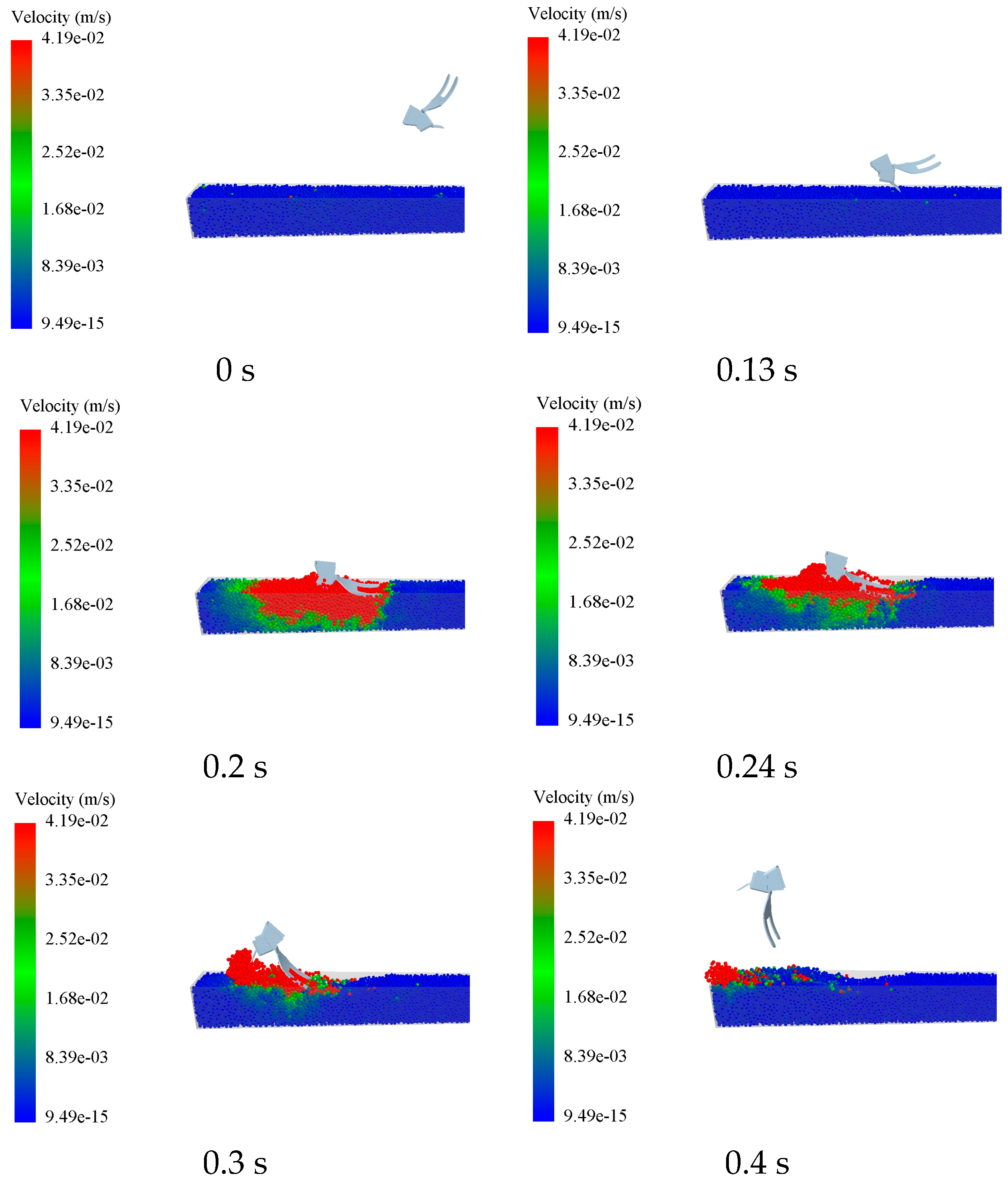
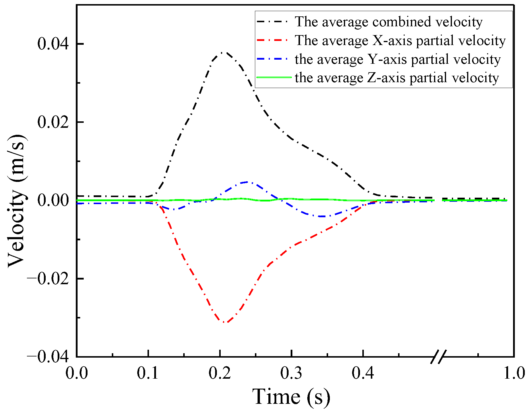
4.1. Soil Disturbance by a Single Duckbill

The simulation results are shown in Figure 8, and the time points of 0 s, 0.13 s, 0.2 s, 0.24 s, 0.3 s, and 0.4 s are selected for analysis. It was observed that before 0.13 s, as the duckbill had no contact with the soil, the soil particles had no perturbation, and the velocities were all 0 m/s; at 0.13~0.2 s, the duckbill broke through the soil, and the velocities of some of the soil particles became bigger; at 0.2~0.24 s, the duckbill was inserted into the soil, and the moving duckbill beak was opened, and the perturbation to the soil reached the maximum; at 0.24~0.3 s, the duckbill slipped out from the soil, and the disturbance gradually decreased; at 0.3~0.4 s, the duckbill left the soil, there was no contact with the soil, and the velocity of soil particles gradually decreased to 0 m/s.
To further investigate the direction of soil particle movement and the variation patterns of the particle velocities in various axial directions under the action of the hole-forming device, a simulation analysis was conducted to examine the average combined velocity of soil particles and the average component velocities along each axis throughout the process from the duckbill’s entry into the soil to its emergence. The simulation results are shown in Figure 9; before 0.13 s, the average combined velocity and the average partial velocity of each axis were 0 m/s. From 0.13 s to 0.4 s, the average combined velocity and the average X-axis partial velocity changed obviously, and the average X-axis partial velocity was negative, the velocity in the Y-axis direction increased first in the negative direction, then in the positive direction and then in the negative direction, and then finally became 0 m/s, and the velocity in the Z-axis direction did not fluctuate; at 0.4~1 s, the average combined velocity and the average partial velocity of each axis returned to 0 m/s. The results show that during the process of duckbill hole forming, the disturbance of the soil is mainly concentrated in the X-axis direction, and the rolling process of the duckbill squeezes the soil and drives the soil particles to move along the negative direction of the X-axis to cause hole formation.

4.2. Effect of Parameters on Hole-Forming Trajectory

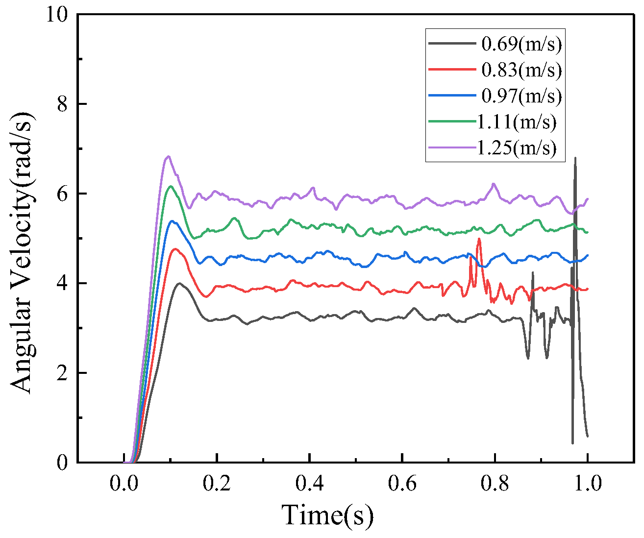
4.2.1. Effect of Forward Speed on Hole-Forming Trajectory

At different forward speeds, the amount of slip of the hole-forming device and the time of action with the soil varies, resulting in different planting depths and individual spacing; during the movement of the cavity-forming apparatus, there is always slip. In order to analyze the change rule of the hole-forming trajectory of the hole-forming device under different forward speeds, the traction angle is 20°, the mass of the hole-forming device is 17 kg, and the forward speed of the hole-forming device is 0.69, 0.83, 0.97, 1.11, and 1.25 m/s as the parameter. The simulation results are shown in Table 4.
With the increase in speed, the pressure of the hole-forming device on the soil first reduced until the vertical direction reached equilibrium, the planting depth decreased, and then because of the continued increase in speed, the hole-forming device appeared to slip, and the planting depth increased; with the increase in speed, the angular velocity of the duckbill rotating also gets bigger and bigger as shown in Figure 10, the individual spacing decreases, the forward speed continues to increase, the duckbill and the role of the soil are not enough, resulting in duckbill slipping, and the individual spacing increases.
At 0.8~0.9 s, the angular velocity of the hole-forming device fluctuates wildly when moving at a forward speed of 0.69 m/s. This is because the duck’s beak disturbs the soil more when the speed is too low, pulling up the small pieces of soil, resulting in a minor rolling resistance and an instantly more significant angular velocity, which then comes into contact with the soil. The angular velocity decreases to an average value.

4.2.2. Effect of Traction Angle on Hole-Forming Trajectory

In the simulation test, the mass of the hole-forming device’s mass is 17.9 kg and the forward speed is 1.25 m/s. The traction angle is set at 0° as the low-level value and 10° as the difference value, and five simulation tests are carried out. The results of the simulation tests are shown in Figure 11.
As shown in Table 5, the trajectory of hole-forming under different traction angles shows that the individual spacing increases and then decreases with the increase in traction angle, with the highest value of 10°; the planting depth gradually decreases with the increase in traction angle. According to the agronomic specification of cotton sowing, the range of traction angle is 10°~30°.

4.2.3. The Effect Mass of the Hole-Forming Device on Hole-Forming Trajectory

A duckbill hole-forming device in the rolling process relies on the hole-forming device’s gravity and soil interaction; the moving duckbill spring is compressed, the moving duckbill opens and completes the seeding, and the hole-forming device’s gravity directly affects when the moving duckbill can open. In this study, the mass of the hole-forming device was set at 15, 16, 17, 18, and 19 kg, respectively. The mass of the hole-forming device was adjusted using a user-defined change in model mass in the RecurDyn software, setting the forward speed to 0.97 m/s and the traction angle to 20°. The simulation results are shown in Table 6: As the mass of the hole-forming device increases, the pressure of the hole-forming device on the soil becomes more extensive, and the longer the size of the duckbill inserted into the soil, the more the depth of the burrow hole also increases; the individual spacing fluctuates less with the increase in the hole-forming device mass.

5. Simulation Optimization

5.1. Optimization Methods

The hole-forming trajectory is affected by several influencing factors. If different factors and different levels are combined as samples for numerical simulation, the computational time cost is too high and the efficiency is low. The orthogonal test effectively reduces the number of samples while ensuring that the weights of the factors and levels on the results are balanced. In this paper, the hole-forming device forward speed, traction angle, and mass of the hole-forming device were used as the test factors, and the planting depth and individual spacing were used as the indexes for evaluating the hole-forming performance. Using the one-factor test and the analysis of the simulation process as a reference, the levels and coded values of each factor were set, as shown in Table 7.
Using Design-Expert 13.0 software to design a three-factor, five-level quadratic rotation orthogonal combination test program, the simulation test results under each parameter combination were filled in, as shown in Table 8.

5.2. Analysis of Test Results

The recorded data sets were analyzed and processed through the experimental design software, and the effects of the hole-forming device forward speed, traction angle, and hole-forming device mass are shown in Table 9. The F-value can identify the primary and secondary influence evaluation indexes, and the ANOVA results show that the primary and secondary influence on planting depth is forward speed > hole-forming device mass > traction angle; the primary and secondary influence on individual spacing is hole-forming device mass > forward speed > traction angle. The R2 coefficient of determination, an essential indicator for determining the linear fit of the regression equation, was 0.97 for the planting depth equation and 0.9811 for the individual spacing equation. From this, it can be judged that 97% of the variation in Y1 is due to X1, X2, and X3, and 98.11% of the variation in Y2 is due to X1, X2, and X3, and the predicted values of the regression equations are highly correlated with the measured values [29].
The p-value can determine whether the effect of regression term parameters is significant or not [30], as shown in Table 8; the effect of X2, X12, X22 on planting depth is highly significant (p < 0.01); the effect of rest of the items on individual spacing is significant (0.01 ≤ p ≤ 0.05); the effect of X1, X2, X3, X12, X1X2, X22, X32 on individual spacing is highly significant (p < 0.01); X1, X3 had an insignificant effect on individual spacing; and the rest of the items had a significant effect on individual spacing (0.01 ≤ p ≤ 0.05).
The quadratic polynomial regression equation between planting depth, individual spacing and test factor coding was established by eliminating the non-significant phase, as shown in the following formula:
Y 1 = 27.5 0.3047 X 1 0.79 X 2 + 0.3201 X 3 + 1.84 X 1 X 2 + 0.9788 X 1 X 3 0.4312 X 2 X 3 + 0.8755 X 1 2 + 1.48 X 2 2
Y 2 = 88.54 0.637 X 1 + 0.7712 X 2 + 1.23 X 3 + 0.925 X 1 X 2 0.325 X 1 X 3 0.7137 X 1 2 + 1.07 X 2 2 0.8551 X 3 2
The response surface can reflect the relationship between the operational performance of the hole-forming device and each experimental factor. The response surface of the hole-forming device’s forward speed, traction angle, mass, and their interactions on planting depth and individual spacing can be obtained using Design-Expert 13.0, as shown in Figure 12 and Figure 13.
The response-surface plots of the two-by-two interaction of forward speed, traction angle, and the hole-forming device mass on planting depth and individual spacing can be obtained from Figure 9 and Figure 10: As the forward speed of the hole-forming device increases, the planting depth and individual spacing first decrease and then increase. This is because as the speed increases, the hole-forming device on the soil pressure first decreases until the vertical direction to reach equilibrium, the planting depth decreases, and then due to the speed continues to increase, the hole-forming device appears to glide, and the planting depth increases; As the speed increases, the angular velocity of the duckbill rotation also increases, the individual spacing decreases, the forward speed continues to increase, the duckbill and soil action is insufficient, resulting in duckbill slippage, and the individual spacing increases; With the increase in the traction angle of the hole-forming device, the vertical upward force becomes more extensive, the pressure of the hole-forming device on the soil becomes smaller, the planting depth has been reduced, and the individual spacing first increases and then decreases; As the mass of the hole-forming device increases, the pressure of the hole-forming device on the soil becomes more significant, and the longer the size of the duckbill inserted into the soil, the more the depth of the burrow hole increases. The individual spacing increases with the mass of the hole-forming device and then tends to stabilize.

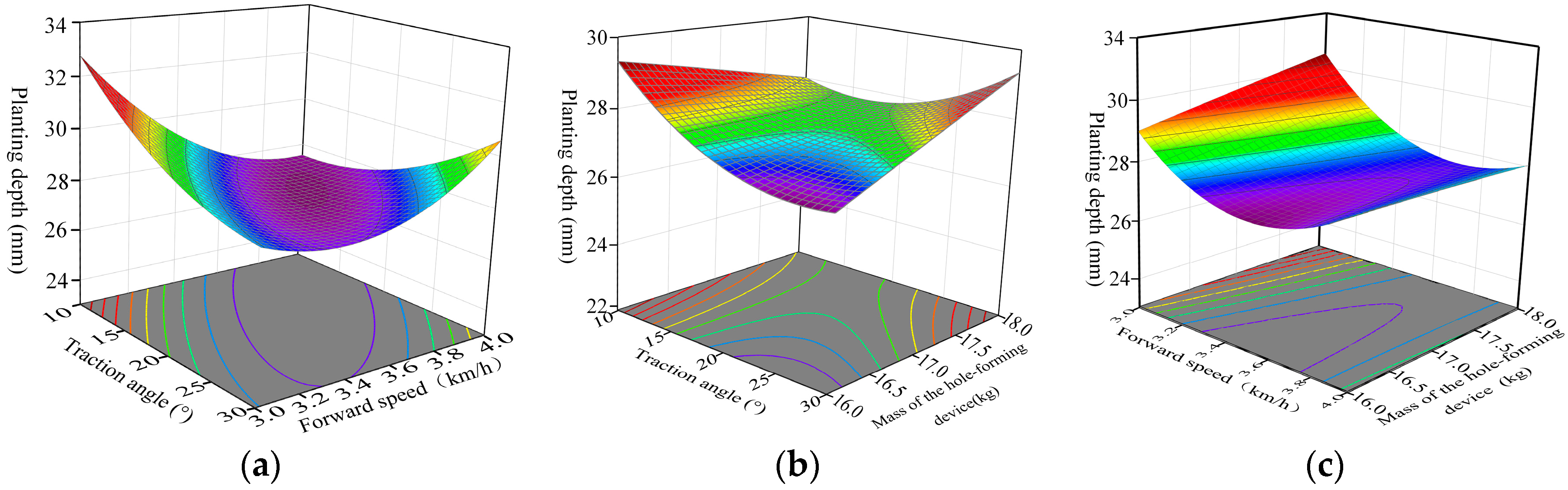
5.3. Parameter Optimization

The depth and spacing at which cotton seeds are planted have an essential effect on the growth and development of cotton. Sowing at a deep depth may result in delayed or low seedling emergence, as the temperature and oxygen levels below the soil surface are unsuitable for seed germination. Also, even if the seeds can germinate, the seedling emergence process requires more energy, which may affect seedling growth and lead to overall slow plant growth. In addition, the higher moisture content in the deeper layers of the soil may increase the chances of certain soil-borne diseases. Sowing at too shallow a depth may result in poor seedling emergence due to external environmental influences such as temperature fluctuations and soil dryness. Moreover, shallow soil dryness does not favor downward root extension, resulting in a shallow root system, which can affect the plant’s wind resistance and water uptake. If the spacing between the plants is too large, the ground will quickly become full of weeds, which will compete with the cotton for nutrients and water, affecting the growth of the cotton. If the spacing is too small, the competition between plants will be intense, which may lead to excess nutrient growth and insufficient reproductive growth, affecting flowering and boll formation. Furthermore, if the plants are too close to each other, this may lead to poor ventilation and light conditions in the field and increasing the incidence of pests and diseases. According to the planting requirements of the local cotton seeds researched, the planting depth of the cotton seeds is 27−28 mm and the individual spacing of the cotton seeds is 85–100 mm.
In order to seek the optimal parameter combinations of the interacting factors, the hole-formation performance regression model was solved by multi-objective optimization, with the constraints shown below:
27 Y 1 28 85 Y 2 100 s t 0.83   m / s X 1 1.11   m / s 10 ° X 2 30 ° 16   kg X 3 18   kg
To meet the agronomic requirements and increase the cotton germination rate and yield, the minimum planting depth and the minimum individual spacing were taken as the optimization objectives.
min Y 1 min Y 2
Using the optimization module in Design-expert 13.0, the hole-forming performance of the hole-former is optimal when the traction angle is 17.3°, the forward speed is 1.11 m/s, and the mass of the hole-forming device is 17.9 kg.

6. Conclusions

This paper takes a duckbilled hole-forming device as the research object and studies the influence of control parameters such as the forward speed, traction angle, and hole-forming device mass on the trajectory of a duckbilled hole-forming device, optimizes the control parameters through simulation and data processing, and searches for the optimization parameter combinations. The change rule of the control parameters on the influence of the hole-formation trajectory was explored, providing methods and ideas for selecting and optimizing the hole-forming device manufacturing parameters. The following are the main conclusions of this study:
  • Through the method of DEM-MBD coupled simulation, it is found that the disturbance of the soil in the process of hole formation by a duckbilled hole-forming device is mainly concentrated in the forward direction and vertical direction of the hole-former, and the hole is formed by squeezing and shearing the soil;
  • The size of the forward speed of a duckbilled hole-forming device directly affects the hole-forming performance of the hole-forming device, and a forward speed that is too small or too large will result in too large a planting depth and individual spacing, which will not be able to meet the agronomic requirements;
  • Through the optimization of the hole-formation performance parameters of the hole-forming device, it is obtained that the hole-formation performance of the hole-forming device is optimal when the traction angle is 17.3°, the forward speed is 1.11 m/s, and the mass of the hole-forming device is 17.9 kg.
In an environment where labor costs are high, and mechanization is dominant, farmers and machinery companies must complete sowing with high quality. Our team researched the difficulties encountered in the local cotton sowing process. It improved the sowing performance by optimizing the parameters of the hole-forming device. However, there still needs to be a gap between the current sowing efficiency and the performance of the sowing machinery and that of the developed countries. Our team will continue to be dedicated to research on the development of agricultural machinery in the future.

Author Contributions

Conceptualization, B.Z. and X.N. and W.C.; methodology, X.N.; software, B.Z.; validation, B.Z., and K.L.; formal analysis, W.C.; investigation, B.Z.; resources, X.N.; data curation, K.L.; writing—original draft preparation, B.Z.; writing—review and editing, B.Z.; visualization, X.N.; supervision, W.C.; project administration, X.N.; funding acquisition, X.N. All authors have read and agreed to the published version of the manuscript.

Funding

This research was supported by grants from the National Natural Science Foundation of China (52065056).

Institutional Review Board Statement

Not applicable.

Data Availability Statement

All relevant data presented in the article are kept at the request of the institution and are therefore not available online. However, all data used in this manuscript are available from the corresponding author.

Conflicts of Interest

The authors declare no conflicts of interest.

References

  1. Yuan, Y.W.; Bai, S.H.; Niu, K. Research progress in the key technologies and equipment for cotton planting mechanization. Trans. Chin. Soc. Agric. Eng. 2023, 39, 1–11. [Google Scholar]
  2. Zhao, L.W.; Jin, R.C.; Sun, R.; Cui, R.M.; Ba, Y.H. Application of Agricultural Information Technology in Cotton Cultivation. Agric. Eng. Technol. 2023, 43, 88–89. [Google Scholar]
  3. Tian, G.R. Cotton mechanical precision sowing technology application points and promotion countermeasures. China South. Agric. Mach. 2024, 55, 62–64. [Google Scholar]
  4. Wang, H.T.; Sun, W.; Zhang, H.; Liu, X.L.; Li, H.; Liu, K.Y. Development of Mechanized Planting Technology on Film. Agric. Equip. Veh. Eng. 2022, 60, 7–11. [Google Scholar]
  5. Yan, J.W.; Wei, S.; Zhang, F.G. Present Research Status and Development Trend of Over-Film Precision Seeding Equipment. Xinjiang Agric. Mech. 2021, 2, 15–19. [Google Scholar] [CrossRef]
  6. Liu, K.Y.; Sun, W.; Zhang, H.; Liu, X.L.; Li, H.; Wang, H.T.; Tian, B. General situation of development of mechanized soil covering technology on film. Agric. Equip. Veh. Eng. 2023, 61, 10–13. [Google Scholar]
  7. Quan, W.; Wu, M.L.; Luo, H.F.; Chen, C.P.; Xie, W. Soil hole opening methods and parameters optimization of pot seedling transplanting machine for rapeseed. Trans. Chin. Soc. Agric. Eng. 2020, 36, 13–21+327. [Google Scholar]
  8. Zhou, G.; Shi, L.R.; Zhao, W.Y.; Xin, S.L.; Yang, X.P. Design and simulation of precision seeder for flax indryland ridge with plastic-film. Agric. Res. Arid. Areas 2019, 37, 245–252. [Google Scholar]
  9. Hou, S.Y.; Ji, Z.C.; Xue, D.H.; Wang, X.; Feng, B.J.; Chen, H.T. Improved Design and Test of Straw Cleaning Device Suitable for No-tillage Seeding Unit. Trans. Chin. Soc. Agric. Mach. 2023, 54, 111–122. [Google Scholar]
  10. Hou, S.Y.; Wang, S.Z.; Zhu, X.X.; Zhang, J.C.; Ji, W.W.; Chen, H.T. Design and Experiment of Side-open Sliding Cutting Film Broken Seeding Unit Based on Straw Fiber Film. Trans. Chin. Soc. Agric. Mach. 2021, 52, 155–165. [Google Scholar]
  11. Liao, Q.X.; Pei, L.M.; Zhang, Q.S.; Wang, L.; Luo, Z.C.; Fu, M.L. Design and Experiment of Rolling Film Cutting and Hole Punching Device for Rapeseed Seeder with Film Mulching and Perforating. Trans. Chin. Soc. Agric. Mach. 2023, 54, 85–98. [Google Scholar]
  12. Bao, Q.Y. Development of a New Bionic Subsoiler Based on DEM. Master’s Thesis, Shandong Agricultural University, Taian, China, 2018. [Google Scholar]
  13. Kim, Y.-S.; Lee, S.-D.; Baek, S.-Y.; Jeon, H.-H.; Lee, J.-H.; Siddique, A.A.; Kim, Y.-J.; Kim, W.-S.; Sim, T.; Yi, S.; et al. Development of DEM-MBD coupling model for draft force prediction of agricultural tractor with plowing depth. Comput. Electron. Agric. 2022, 202, 107405. [Google Scholar] [CrossRef]
  14. Hasimu, A.; Chen, Y. Soil disturbance and draft force of selected seed openers. Soil Tillage Res. 2014, 140, 48–54. [Google Scholar] [CrossRef]
  15. Zhao, H.; Li, H.; Ma, S.; He, J.; Wang, Q.; Lu, C.; Zheng, Z.; Zhang, C. The effect of various edge-curve types of plain-straight blades for strip tillage seeding on torque and soil disturbance using DEM. Soil Tillage Res. 2020, 202, 104674. [Google Scholar] [CrossRef]
  16. Li, J.W.; Li, X.Y.; Hu, B.; Gu, T.L.; Wang, Z.J.; Wang, H.L. Analysis of the resistance reduction mechanism of potato bionic digging shovels in clay and heavy soil conditions. Comput. Electron. Agric. 2023, 214, 108315. [Google Scholar] [CrossRef]
  17. Chen, X.G.; Zhao, Y. Development of double-film mulch precision planter for cotton seeding. Trans. Chin. Soc. Agric. Eng. 2010, 26, 106–112. [Google Scholar]
  18. Chen, X.G.; Wang, M. Study on Key Factors of the Duckbill Punch Roller-type Pneumatic Metering Device. J. Agric. Mech. Res. 2011, 33, 130–133+137. [Google Scholar]
  19. Huang, Y.H.; Quan, L.Z.; Hu, G.F.; Quan, W.; Shi, F.G. Calibration of Discrete Element Contact Parameters for Various Materials and Soils with Different Moisture Content. J. Agric. Sci. Technol. 2024, 26, 98–109. [Google Scholar]
  20. Wang, X.; Zhang, S.; Pan, H.; Zheng, Z.; Huang, Y.; Zhu, R. Effect of soil particle size on soil-subsoiler interactions using the discrete element method simulations. Biosyst. Eng. 2019, 182, 138–150. [Google Scholar] [CrossRef]
  21. Zhou, H.B.; Chen, Y.; Mohammad, A.S. Modelling of soil–seed contact using the Discrete Element Method (DEM). Biosyst. Eng. 2014, 121, 56–66. [Google Scholar] [CrossRef]
  22. Jia, C.P. A DEM-Based Study on the Mechanism of Cup-Soil Interaction in a High-Speed Transplanting Machine for Cavity Tray Seedlings. Master’s Thesis, Jiangsu University, Zhenjiang, China, 2021. [Google Scholar]
  23. Wa, L.P.C.; Li, Y.L.; Su, C.; Zhao, H.; Dong, X.Q.; Song, J.N.; Wang, J.C. Simulation of soil tillage characteristics and influence analysis of particle sphere type based on EEPA contact model. J. China Agric. Univ. 2021, 26, 193–206. [Google Scholar]
  24. Han, W.; Wang, S.Z.; Zhang, Q.; Tian, Y.H. Discrete element parameter calibration of micron sized powder particles based on JKR contact modlel. China Powder Sci. Technol. 2021, 27, 60–69. [Google Scholar]
  25. Wang, W.D.; Liu, X.W. Soil-water characteristic curves based on the non-contact case of three particles of unequa size. J. Nanchang Univ. (Eng. Technol.) 2023, 45, 38–43+58. [Google Scholar]
  26. Hang, C.; Gao, X.; Yuan, M.; Huang, Y.; Zhu, R. Discrete element simulations and experiments of soil disturbance as affected by the tine spacing of subsoiler. Biosyst. Eng. 2018, 168, 73–82. [Google Scholar] [CrossRef]
  27. Wu, P.; Zhang, X.; Zeng, Z.; Chen, Y. DEM simulation of subsoiling for soil disturbance as affected by soil layering and working speed. Smart Agric. Technol. 2024, 7, 100385. [Google Scholar] [CrossRef]
  28. Sun, J.; Wang, Y.; Ma, Y.; Tong, J.; Zhang, Z. DEM simulation of bionic subsoilers (tillage depth > 40 cm) with drag reduction and lower soil disturbance characteristics. Adv. Eng. Softw. 2018, 119, 30–37. [Google Scholar] [CrossRef]
  29. Ni, X.D.; Xu, G.J.; Wang, Q.; Peng, X.R.; Wang, J.; Hu, B. Design and Experiment of Pneumatic Cylinder Array Precision Seed-metering Device for Cotton. Trans. Chin. Soc. Agric. Mach. 2017, 48, 58–67. [Google Scholar]
  30. Lu, B.; Ni, X.; Li, S.; Li, K.; Qi, Q. Simulation and Experimental Study of a Split High-Speed Precision Seeding System. Agriculture 2022, 12, 1037. [Google Scholar] [CrossRef]
Figure 1. Sketch of the structure of a duckbilled hole-forming device. 1. Chock 2. Pressure plate 3. Arc-shaped seed-blocking ring 4. Seed baffle 5. Dividing grid 6. Moving duckbill 7. Belt 8. Fixed duckbill 9. Dynamic disk 10. Axis.
Agriculture 14 00843 g001
Figure 2. Motion diagram of a duckbilled hole-forming device.
Agriculture 14 00843 g002
Figure 3. Contour diagram of soil hole.
Agriculture 14 00843 g003
Figure 4. The force of the hole-forming device.
Agriculture 14 00843 g004
Figure 5. Coupling simulation flowchart.
Agriculture 14 00843 g005
Figure 6. Field trials.
Agriculture 14 00843 g006
Figure 7. Simulation and experimental measurement results.
Agriculture 14 00843 g007
Figure 8. Soil particle velocity diagram.
Agriculture 14 00843 g008
Figure 9. Average velocity of each axis of soil particles.
Agriculture 14 00843 g009
Figure 10. Angular velocity change diagram of the hole-forming device.
Agriculture 14 00843 g010
Figure 11. Hole-forming trajectory under traction angles.
Agriculture 14 00843 g011
Figure 12. Effect of traction angle, forward speed, and mass of the hole-forming device on planting depth, (a) effect of traction angle and forward speed on planting depth; (b) effect of traction angle and mass of the hole-forming device on planting depth; (c) effect of forward speed and mass of the hole-forming device on planting depth.
Agriculture 14 00843 g012
Figure 13. Effect of traction angle, forward speed, and mass of the hole-forming device on individual spacing, (a) effect of traction angle and forward speed on individual spacing; (b) effect of traction angle and mass of the hole-forming device on individual spacing; (c) effect of forward speed and mass of the hole-forming device on individual spacing.
Agriculture 14 00843 g013
Table 1. The movement of the hole-forming device model.
Serial NumberUnitKinematic Pair
1Ground, coupling shaftTranslate
2End cap assembly, coupling shaftFixed
3Dividing grid combination, coupling shaftRevolute
4Moving duckbill combination, dividing grid combinationRevolute
5Moving duckbill combination, dividing grid combinationSpring
Table 2. Soil discrete element modeling parameters.
ParameterValue
Soil particle density/(kg·m−3)1569
Density of steel/(kg·m−3)7801
Soil particle radius/mm3
Soil Poisson’s ratio0.36
Steel Poisson’s ratio0.29
Shear modulus of soil/MPa1 × 106
Shear modulus of steer/MPa8.02 × 1010
Restitution coefficient between soil particles0.4
Restitution coefficient of soil and steel0.5
Static friction coefficient between soil particles0.49
Static friction coefficient between soil and steel0.46
Dynamic friction coefficient between soil particles0.29
Dynamic friction coefficient between soil and steel0.15
Normal contact stiffness coefficient between soil–soil particles/(N/m3)1.9 × 105
Tangential contact stiffness coefficient between soil–soil particles/(N/m3)1.4 × 105
Critical normal stress between soil and soil particles/Pa55,000
Critical tangential stress between soil and soil particles/Pa55,000
Bonding radius/mm3.5
Table 3. Simulation and field test results.
NumberSimulated Values for Planting DepthReal Values of Planting DepthSimulated Values for Individual SpacingReal Values of Individual Spacing
127.4727.6289.1789.21
227.5626.9888.9588.73
327.5327.4189.2689.05
427.927.8888.7089.12
527.4227.5689.0288.97
Table 4. Effect of forward speed on hole-forming trajectory.
Forward Speed (m/s)Planting Depth (mm)Individual Spacing (mm)
0.6930.6792.43
0.8326.7889.73
0.9729.0889.48
1.1129.1989.91
1.2529.3291.01
Table 5. Effect of traction angle on hole-forming trajectory.
Traction Angle (°)Planting Depth (mm)Individual Spacing (mm)
029.7888.78
1029.4689.59
2026.7189.41
3026.6889.36
4026.5089.50
Table 6. The influence of the mass of the hole-forming device on the hole-forming trajectory.
Mass of the Hole-Forming Device (kg)Planting Depth (mm)Individual Spacing (mm)
1527.5089.31
1628.1289.44
1728.2790.03
1828.7389.70
1929.1889.18
Table 7. Test factor level and coding.
CodingExperimental Factors
Traction Angle X1/(°)Forward Speed X2/(m/s)Mass of the Hole-Forming Device X3/(kg)
−1.6823.20.7515.3
−1100.8316
0200.9717
1301.1118
1.68236.81.1918.7
Table 8. The results of quadratic rotation orthogonal center combination test scheme.
Test Serial NumberExperimental FactorsEvaluating Indicator
X1X2X3Planting Depth Y1/%Individual Spacing Y2/%
1−1−1−132.9687.3
21−1−126.7285.1
3−11−129.1487.1
411−129.6288.1
5−1−1132.8590.3
61−1129.986.3
7−11126.6890.3
811131.790.5
9−1.6820029.9687.5
101.6820029.6885.3
110−1.682033.1790.4
1201.682029.992.5
1300−1.68226.883.9
14001.68227.888.1
1500027.788.7
1600027.5188.65
1700026.9488.32
1800028.2288.31
1900027.6588.54
2000026.9488.34
2100026.9788.15
2200027.788.47
2300027.8989.4
Table 9. Analysis of variance of regression equations.
SourcePlanting DepthIndividual Spacing
dfMean SquareF-Valuep-ValuedfMean SquareF-Valuep-Value
Model910.4646.740.0001 **98.9674.860.0001 **
X111.275.670.0333 *15.5446.320.0001 **
X218.5238.100.0001 **18.1267.870.0001 **
X311.406.250.0265 *120.82174.020.0001 **
X1X2126.97120.560.0001 **16.8557.200.0001 **
X1X317.6634.250.0001 **10.84507.060.0197 *
X2X311.496.650.0229 *10.24502.050.1761
X12112.1854.430.0001 **18.0967.630.0001 **
X22134.89155.940.0001 **118.25152.540.0001 **
X3210.00380.01700.8984111.6297.090.0001 **
Residual130.2238 130.1197
Lack of Fit50.24551.170.401450.09600.71410.6303
Pure Error80.2101 80.1344
Cor Total22 22
Notes: * indicates significant differences (p < 0.05) and ** indicates highly significant differences (p < 0.01).
Disclaimer/Publisher’s Note: The statements, opinions and data contained in all publications are solely those of the individual author(s) and contributor(s) and not of MDPI and/or the editor(s). MDPI and/or the editor(s) disclaim responsibility for any injury to people or property resulting from any ideas, methods, instructions or products referred to in the content.

