Article

Design and Experimentation of Rice Seedling Throwing Apparatus Mounted on Unmanned Aerial Vehicle

1
Nanjing Institute of Agricultural Mechanization, Ministry of Agriculture and Rural Affairs, Nanjing 210014, China
2
Graduate School of Chinese Academy of Agricultural Sciences, Beijing 100083, China
*
Authors to whom correspondence should be addressed.
Agriculture 2024, 14(6), 847; https://doi.org/10.3390/agriculture14060847
Submission received: 16 April 2024 / Revised: 21 May 2024 / Accepted: 27 May 2024 / Published: 28 May 2024

Abstract

:
In order to further exploit the production advantages of rice throwing, this paper proposes a systematically designed throwing device suitable for integration with unmanned aerial vehicles (UAVs). The device primarily comprises a seedling carrying and connection system, a seedling pushing mechanism, and a seedling guiding device. The operational principles and workflow of the device are initially elucidated. Subsequently, an analysis of factors influencing rice throwing effectiveness is conducted, with throwing height, working speed, and the bottom diameter of the seedling guide tube identified as key factors. Seedling spacing uniformity and seedling uprightness are designated as performance indicators. A three-factor, three-level response surface experiment is conducted, yielding regression models for the experimental indicators. Through an analysis of the response surface, the optimal parameter combination is determined to be a throwing height of 142.79 cm, a working speed of 55.38 r/min, and a bottom diameter of the seedling guide tube of 43.51 mm. At these parameters, the model predicts a seedling spacing uniformity of 88.43% and a seedling uprightness of 88.12%. Field experiments validate the accuracy of the optimized model results. Experimental data indicate that under the optimal operational parameters calculated by the regression model, the seedling spacing uniformity is 86.7%, and the seedling uprightness is 84.2%. The experimental results meet the design requirements, providing valuable insights for UAV rice-throwing operations.

1. Introduction

Rice constitutes a primary staple crop in China. Rice seedlings transplanted through the process of seedling throwing exhibit growth advantages such as rapid growth and prolific tillering. This practice contributes to the enhancement of rice yield, demonstrating considerable potential for further development [1,2,3,4]. To further exploit the advantages of rice throwing, mechanized rice transplanters have rapidly evolved from disorderly to orderly operations [5]. Domestically, orderly rice transplanters mainly include the following three methods: pneumatic, roller-type, and clamping, which transfer seedlings into the field through seedling guides. Pneumatic transplanters occasionally encounter issues with nozzle failure, resulting in unstable operation. Roller-type transplanters may cause damage to seedlings. Clamping transplanters are prone to drift issues and require higher field preparation standards [6,7,8]. Additionally, the terrain in hilly and mountainous areas is characterized by small agricultural plots and steep slopes. Ground machinery operation is challenging, and field-to-field transitions pose difficulties. The mechanization level of rice cultivation in domestic hilly areas is less than 10% [9,10,11].
To address these issues, this study aims to leverage the advantages of UAVs for seedling throwing operations. UAV operations are characterized by rapid execution speed and excellent maneuverability [12]. Using UAVs allows for liberation from the structural constraints inherent in ground-based machinery. This facilitates the adjustment of seedling throwing height, thereby enhancing planting effectiveness. In hilly and mountainous terrain, UAVs experience lesser influence from topography. This is another advantage that distinguishes it from ground-based machinery.
Research on agricultural UAVs includes aspects such as agricultural monitoring and disaster assessment using remote sensing technology [13,14,15,16]. In terms of UAV operations, applications such as fertilization, pesticide spraying, and seeding have been explored [17,18,19,20]. There has been limited research on UAV rice throwing. Therefore, investigating the application of UAVs for solid material handling is of significant reference value to this study [21,22]. In the fertilization stage of UAV operations, flight altitude and spreading speed significantly affect fertilization effectiveness [23,24,25]. In the seeding stage, agricultural UAVs mainly employ the following two forms of seeding: disorderly broadcasting and orderly row broadcasting [26]. Orderly row broadcasting typically requires guiding channels to control the seed distribution. Song Cancan et al. [27] have studied the wind distribution around multi-rotor UAVs and designed a pneumatic rice seeding device. This device is regulated by a groove wheel to control the amount of seed discharge. The high-speed airflow generated by the fan accelerates the expulsion of rice seeds. Subsequently, the rice seeds are dispersed through separate and independent diversion channels. This method enhances the controllability and uniformity of rice seed sowing. Liu Wei et al. [28] studied the stability of the displacement of a sowing device under a fixed sowing speed condition. He developed a rice seeding device capable of simultaneously sowing five rows. The seeding rate of this device can be adjusted according to the operational requirements.
In conclusion, operational speed, flight altitude, and guiding devices are important factors influencing the orderly operation of UAVs. In recent years, domestic agricultural UAVs have seen rapid development, with continuous expansion of their operational capabilities and significant enhancement of their performance. With the increasing market ownership of UAVs, a deep material technology foundation has been laid for orderly seedling-throwing by UAVs. This paper presents the design of a UAV-mounted sequential rice seedling throwing apparatus. The operational parameters of this device were optimized through bench testing. The validation of the device was conducted through field trials. The aim is to provide design references for expanding the production applications of UAVs and complement existing seedling-throwing machinery types.

2. Materials and Methods

2.1. Overall Structure and Workflow

The UAV-mounted rice-throwing device comprises the seedling carrying and connection system, the seedling pushing mechanism, and the seedling guiding mechanism, as illustrated in Figure 1. The MG-1P agricultural UAV is chosen as the power platform. This UAV is manufactured by DJI, located in Shenzhen, China. It has a rated payload of 10 kg and a maximum flight time of approximately 9 min when fully loaded. The seedling carrying and connection system is placed on a specially designed landing gear, with the seedling pushing mechanism mounted at the bottom of the seedling carrying and connection system. The seedling guiding mechanism is installed beneath the seedling carrying and connection system and the seedling pushing mechanism. The devices that the UAV needs to suspend are all manufactured using 3D printing technology (manufactured by Wenext, headquartered in Shenzhen, China). Their total mass is approximately 5.2 kg, and when fully loaded with seedlings, the overall weight does not exceed 9.8 kg.
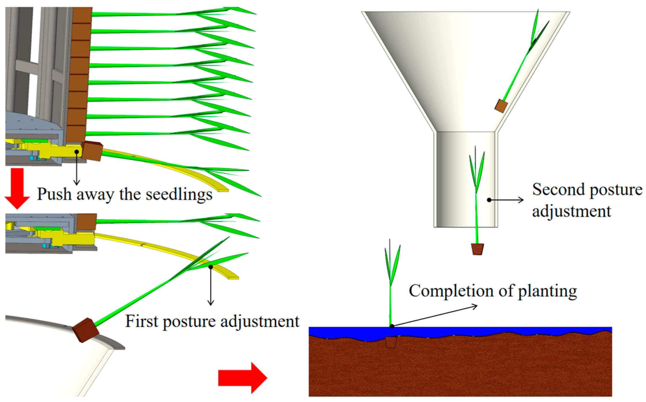
Based on the operational status during UAV operation, the process can be divided into four stages. First, during the preparation stage, well-nurtured rice bowl seedlings are preloaded into the seedling carrying mechanism before UAV operation. The entire device is then placed on the docking frame. Second, during the seedling retrieval stage, the UAV is remotely controlled to fly above the rice seedling carrying and connection system, hover at an appropriate altitude, and then connect with the UAV using specific mechanical claws. Third, during the operation stage, the UAV suspends the rice seedling throwing apparatus and flies to the designated field. The UAV flies at a constant speed along the planned route. Simultaneously, the remote-controlled seedling-pushing mechanism starts operating. When the first seedling in the seedling slot is ejected, the remaining seedlings fall successively with the assistance of counterweight blocks. Rice seedlings are continuously pushed into the seedling guiding device at a constant speed. Subsequently, the seedlings fall into the field under the combined influence of their own gravity and the airflow generated by the UAV’s rotors. The planting process is illustrated in Figure 2. Finally, after the seedling throwing is completed, the UAV flies back above the docking frame. Simultaneously, using a remote control, it opens the mechanical claw to detach from the seedling throwing apparatus. Afterward, the UAV flies toward another seedling-loaded throwing apparatus, repeating the above process in a cycle.

2.2. Working Principle

2.2.1. Rice Seedling Carrying and Connection System

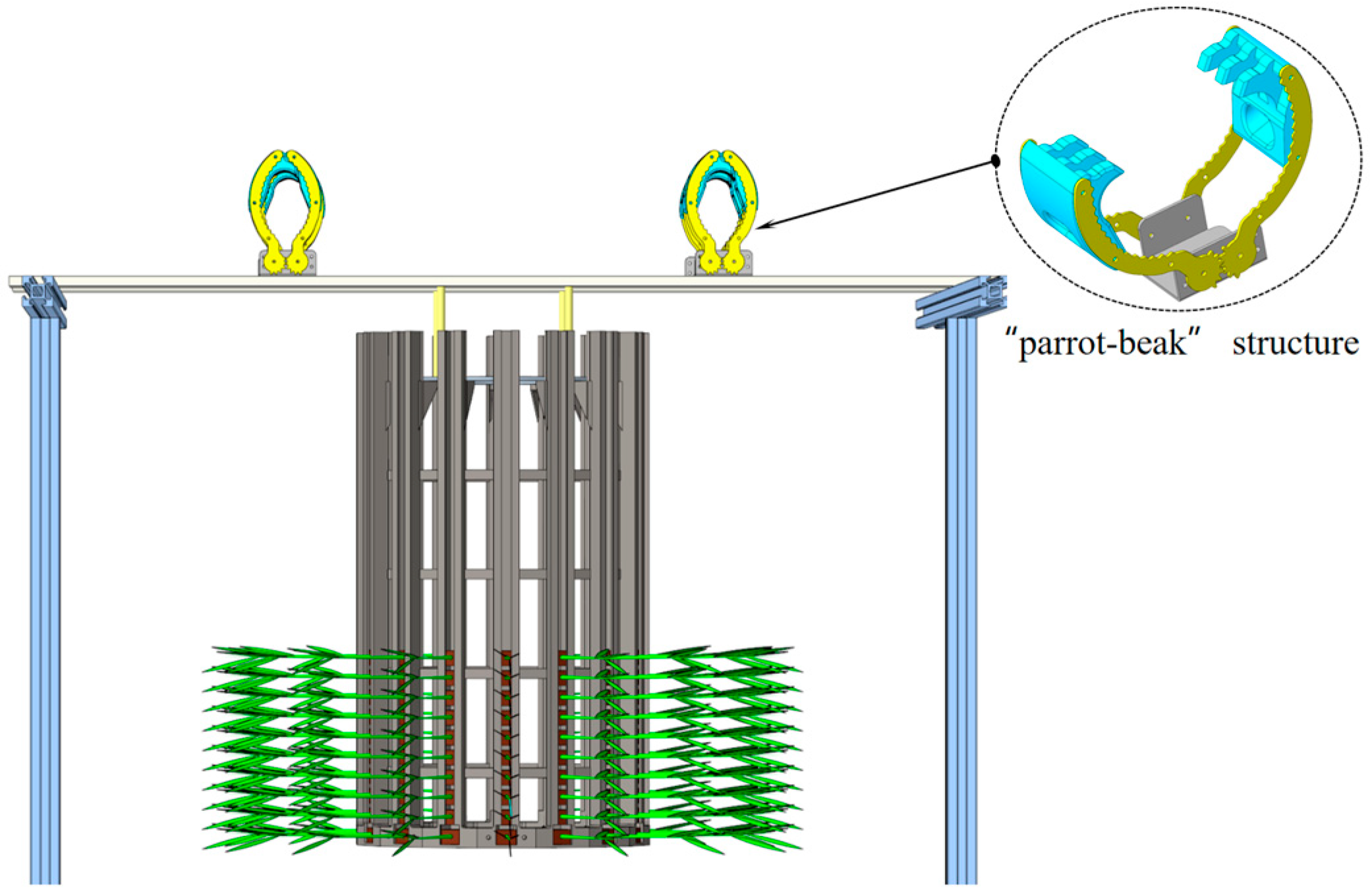
The seedling carrying and connection system is employed for both loading seedlings and connecting to the UAV. As shown in Figure 3, it consists of two main parts as follows: the seedling carrying box and the connection mechanism. In this study, the traditional tray-in-a-box approach was abandoned, and a ring-stacked seedling carrying box was introduced to facilitate the installation of the UAV. The height of the seedling carrying box is 900 mm. It consists of 16 seedling slots and can carry up to 960 rice seedlings. To avoid the entanglement of leaves, the seedling slots are evenly distributed on a circle with a diameter of 300 mm. The advantage of the circular distribution is that the consistent position of the seedlings can be easily adjusted. Even if the seedlings are pushed out at different positions, there is no cumulative positional error. At the bottom of each seedling tank, there is a 12 mm diameter hole for the push rod and a seedling outlet, and a top cover is installed on the top of the seedling carrying box. It serves to improve the overall structural strength and provides a mounting position for the connecting mechanism. The connection mechanism comprises four specially designed claws arranged in a rectangular distribution and two cantilever beams. The specialized clamp utilizes a parrot-beak-like comb-shaped claw, altering the force distribution of the clamp. It transforms the lateral clamping force acting on the mechanical claw into longitudinal pressure on the “parrot beak” structure. This pressure further differentiates into shear force on the bolts connecting the claws, ensuring the stability of the connection. The connection mechanism is connected to the top cover of the seedling carrying box via four copper screws.

2.2.2. Seedling Pushing Mechanism

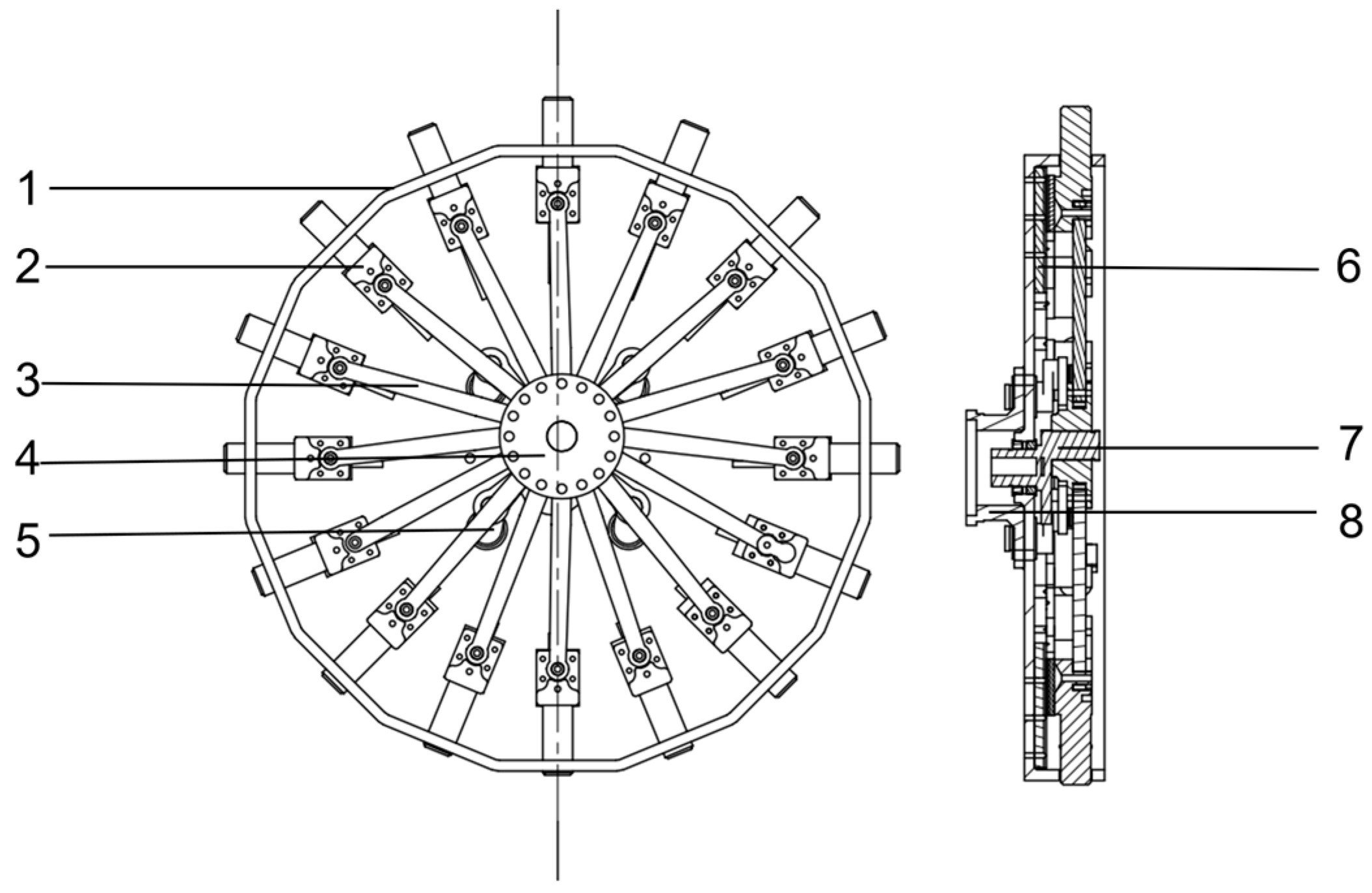
The seedling pushing mechanism is utilized to sequentially push rice seedlings out of the seedling carrying box in a predetermined order. Its internal structure is illustrated in Figure 4. The motor base is mounted on the back of the chassis. Within the recess of the chassis, there are 16 identical-sized push rods and connecting rods installed. The push rods are secured onto sliders (MGN7C, manufactured by HIWIN, headquartered in Taiwan, China), ensuring linear movement. At the end face of each push rod, there is a layer of elastic material adhered to prevent damage to the rice bowl substrate during seedling pushing. The distance between the follower crankshaft and the primary crankshaft remains constant. While the length of the connecting rods maintains a fixed proportion to the center distance of the primary crankshaft. The disk is the core component of the seedling-pushing mechanism. It is connected to the follower crankshaft at the bottom, connected to the connecting rods at the top, and linked to the primary crankshaft in the middle section. The motor (42GA775, manufactured by Vantel, headquartered in Jiangsu, China) is connected to the center of the chassis via a primary crankshaft. When the motor drives the main crankshaft to rotate one full circle, it sequentially pushes out 16 rice seedlings.
The seedling pushing mechanism consists of two types of four-bar linkages combined. The primary crankshaft, follower crankshaft, and disk form a double-crank mechanism. The disk, connecting rod, and push rod form a crank-slider mechanism. In the double-crank mechanism, the motion of each point on the disk follows a circular trajectory consistent with the end of the primary crankshaft. Thus, this point and the center of the hidden trajectory can serve as the crank in the crank-slider mechanism. With this design approach, it is possible to achieve a single motor input and multiple pushrod outputs.
Taking the end actuator of the seedling pushing mechanism as the research subject, the schematic diagram of its mechanism motion is illustrated in Figure 5, where a Cartesian coordinate system is established. The rotated center of the primary crankshaft after translation is the origin O. The direction of the push rod axis is the x-axis and the vertical direction is the y-axis. Here, ab represents the primary crankshaft, with a length of l1, and bc represents the connecting rod with a length of l2. When the primary crankshaft rotates at an angle α, the angle between the push rod axis and the connecting rod is β, at which point the distance of the slider from the rotation center is L.
During the crank rotation, the primary crankshaft and connecting rod are twice in the same straight line, the crank positions are ab1 and ab2, which correspond exactly to the two limit positions of the slider, and their distances from the center of rotation are Lmax and Lmin, respectively, which can be computed to derive the push rod strokes as follows:
s = L max L min = 2 × l 1
The height of the rice seedling bowl used in this article is 18 mm. To ensure that the rice seedlings can be fully pushed out, according to Equation (1), the length of the main shaft should be at least 9 mm. Without affecting the working performance, and to ensure a more compact coordination of each part, the dimensions of each component are finally determined. The center distance between the primary crankshaft and the follower crankshaft is 12 mm. The length of the connecting rod is 72 mm. The diameter of the push rod is 12 mm. The diameter of the disk is 50 mm. The diameter of the outer circle of the seedling pushing chassis is 254 mm.
The closed vector equation of the mechanism is as follows:
L 1 + L 2 = L l 1 e i α + l 2 e i β = L
Expanding Equation (2) using Euler’s formula as follows:
L = l 1 cos α + l 2 cos β l 1 sin α l 2 sin β = 0
Differentiating Equation (2) yields the velocity equation for the slider L as follows:
l 1 ω 1 i e i α + l 2 ω 2 i e i β = V l
Expanding Equation (4) using Euler’s formula as follows:
l 1 ω 1 i cos α + l 1 ω 1 sin α + l 2 ω 2 i cos β l 2 ω 2 sin β = V l V l = l 1 ω 1 sin α l 2 ω 2 sin β
where L represents the distance from the slider to the center of rotation; l1 denotes the distance from the crankshaft center; l2 stands for the length of the connecting rod; α represents the angle turned by the crankshaft; β indicates the angle of the connecting rod; ω1 represents the angular velocity of the crankshaft; and ω2 represents the angular velocity of the connecting rod.
From Equation (3), it can be observed that when the end displacement of the push rod is maximal, α = 0° and β = 180°, or when the end displacement of the push rod is minimal, α = 180° and β = 0°. Substituting these values into Equation (3) reveals that the velocity of the push rod at these points is zero. This reduces the risk of damaging the seedling matrix. Additionally, the positions of the push rod at any two symmetric locations within the transplanting mechanism are identical, but their trends of variation are opposite. Within the 180° division, the values of α and β for any given phase of the push rod are unequal. It indicates that the motion states of the push rod correspond differently to each phase. This validates the feasibility of gradual transplanting.
The operation process of a single push rod is illustrated in Figure 6a, which depicts the following three sequential positions: the origin, midpoint, and apex positions. These positions correspond to the beginning, middle, and end stages of seedling transplantation, respectively, indicating the relative positions of the seedlings and the transplanting mechanism. As depicted in Figure 6b, the origin position aligns with the bottom end face of the seedling trough, while the apex position aligns with the seedling ejection point. Building upon this foundation, sixteen push rods initiate reciprocating motions in the same sequential order, as shown in Figure 6c. When push rod 1 reaches the apex position, the seedling is completely ejected from the trough, marking the completion of the seedling pushing process. Meanwhile, push rod 2 reaches the midpoint position with its velocity directed outward along the axis, indicating that the seedling is about to be ejected. Conversely, push rod 16, the last push rod in the rotation direction, also reaches the midpoint position with its velocity directed inward along the axis. This indicates that the seedlings have been pushed out before push rod 1.

2.2.3. Seedling Guiding Device

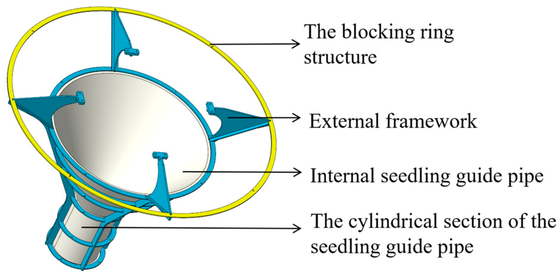
The seedling guiding apparatus is utilized to adjust the posture of rice seedlings during transplantation, ensuring that the root portion of the seedlings faces downward and descends in an upright manner, as depicted in Figure 7. The blocking ring structure restricts the movement of the seedling tip, facilitating the seedling bowl to drop first. The conical section of the seedling guide pipe concentrates the landing position of rice seedling bowls. The cylindrical narrowing section of the guide pipe enhances the uprightness of the seedlings. In order to reduce the overall weight of the device, it comprises an external framework and internal seedling guide pipe. The external framework is securely fastened to the seedling carrier frame using bolts. The internal seedling guide pipe is positioned within the external framework, enabling adjustment of the rice seedling drop channel. Since the external framework bears the primary load, the internal seedling guide pipe can be made as thin as possible. By maintaining seedling guidance functionality, the overall weight of the guide tube can be significantly decreased.

3. Working Performance Test

3.1. Platform Test

The platform test in this study utilized a square soil trough provided by the Nanjing Agricultural Mechanization Research Institute of the Ministry of Agriculture and Rural Affairs. The dimensions of the trough are 500 cm × 100 cm × 30 cm. According to the requirements for rice seedling throwing, the soil in the trough needs to undergo soaking, pulping, and settling treatment. Rice seedlings selected for throwing should be at the three-leaf stage, with the height of the seedlings ranging between 160 and 180 mm. The experimental platform is depicted in Figure 8. The UAV was securely fastened to the platform and rotated at idle speed during the experiments. The seedling throwing apparatus could be directly placed on the square frame. A motor was used to drive a synchronous belt for moving the platform.

3.1.1. Test Conditions

To investigate the effects of seedling throwing height, primary crankshaft working speed, and bottom diameter of the seedling guide tube on the rice seedling throwing performance. These factors were chosen as the three variables in the experiment. The spacing pass rate and the uprightness pass rate were selected as the evaluation criteria. The expressions for each criterion are as follows:
U = V 0 V × 100 %
I = M 0 V × 100 %
where U represents the spacing pass rate; I denotes the qualified rate of rice seedling uprightness; V0 stands for the number of qualified seedlings with appropriate plant spacing within the measured area; M0 represents the number of upright seedlings counted within the measured area; and V represents the total number of seedlings measured within the measured area.
In this experiment, the standard plant spacing for transplanting is 150 mm. To maintain stable plant spacing, the rotational speed of the main shaft is kept in linkage with the flight speed of the UAV. Each rotation of the primary crankshaft will push out 16 rice seedlings. The flight speed of the UAV at this point is shown in Equation (8). Design-Expert 10 was utilized to design a three-factor, three-level quadratic orthogonal experimental design. After verification, it was determined that the throwing height should be selected between 120 and 160 cm; the primary crankshaft working speed should range from 45 to 75 r/min; and the bottom diameter of the seedling guide tube should be between 40 and 60 mm. Table 1 presents the influencing factors and their levels.
v = 16 q n 60
where v represents the flight speed of the UAV, m/s; q represents the standard plant spacing, m; and n represents the rotational speed of the primary crankshaft, rpm.

3.1.2. Results and Discussion

The experimental results are presented in Table 2. Using Design-Expert 10 software, a multivariate regression fitting analysis was conducted to establish quadratic polynomial regression models for the spacing pass rate, Y1, and the uprightness pass rate, Y2, as shown in Equations (9) and (10). Subsequently, variance analysis was performed on the regression equations, with results detailed in Table 3.
Y 1 = 87.92 0.42 X 1 1.24 X 2 2.76 X 3 + 0.4 X 1 X 2 0.15 X 1 X 3 0.57 X 2 X 3 0.9 X 1 2 1.42 X 2 2 3.17 X 3 2
Y 2 = 87.84 0.93 X 1 0.28 X 2 1.58 X 3 0.025 X 1 X 2 0.13 X 1 X 3 + 0.22 X 2 X 3 2.16 X 1 2 1.46 X 2 2 1.36 X 3 2
As shown in Table 3, the significance levels in both regression models are highly significant; all lack-of-fit terms are greater than 0.05, indicating a high degree of fit for the regression models. Therefore, the working parameters of the transplanting device can be optimized using this model.
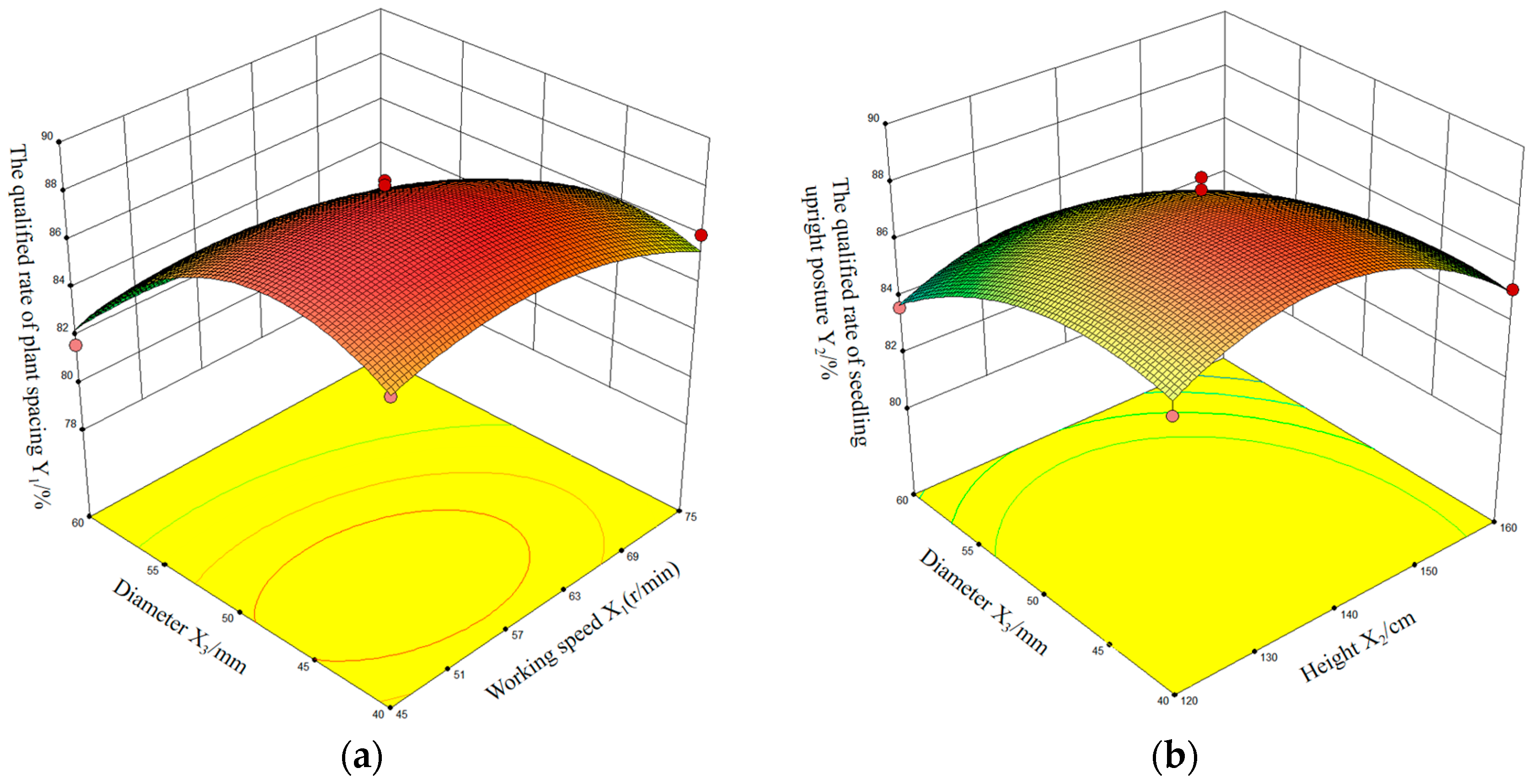
From the analysis of Table 3, it is evident that the working speed of the throwing mechanism and the diameter of the seedling guide tube have the most significant impact on the spacing pass rate in the model, with their interaction also being highly significant. Similarly, for the uprightness pass rate, the throwing height and the diameter of the seedling guide tube have the most significant impact on the model, with their interaction also being highly significant. To further analyze the interactive effects of throwing height, the working speed of the throwing mechanism, and the bottom diameter of the seedling guide tube on the spacing pass rate and the uprightness pass rate, response surface plots were generated using Design-Expert 10 software, as depicted in Figure 9.
To achieve the best transplanting effect and obtain the optimal working parameters for each influencing factor, Design-Expert 10 software was utilized to optimize and solve for the throwing height, working speed, and diameter of the bottom opening of the seedling guide tube. The constraint conditions are as shown in Equation (11). When the throwing height is 142.79 cm, the working speed is 55.38 r/min, and the diameter of the seedling guide tube is 43.51 mm, the spacing pass rate is 88.43%, and the uprightness pass rate is 88.12%.
max   Y 1 ( X 1 , X 2 , X 3 ) max   Y 2 ( X 1 , X 2 , X 3 ) s . t . 120 < X 1 < 160 45 < X 2 < 75 40 < X 3 < 60

3.2. Field Test

To validate the actual planting effect of the UAV orderly throwing device, field experiments were conducted in rice fields at the Baima Experimental Base in Nanjing City, Jiangsu Province. Based on the optimal operating parameters obtained from the platform test, the UAV flight speed was set to 2.2 m/s, the seedling throwing height was set to 143 cm, the primary crankshaft working speed was 55 r/min, and the bottom diameter of the seedling guide tube was 44 mm. The experimental process is depicted in Figure 10.
Through experimentation, the spacing pass rate was determined to be 86.7%, while the uprightness pass rate was 84.2%. The experimental findings align with the anticipated design objectives, albeit marginally lower than the optimized model’s predictions. This variance is attributed to disparities between the laboratory settings and the field environment. In practical rice paddy operational settings, the effectiveness of throwing seedlings is subject to the influence of environmental wind conditions. Furthermore, distinctions in soil composition between the laboratory and the experimental field contribute to non-uniform soil hardness and varying water depths across different areas of the experimental site. These factors collectively contribute to a slight decrease in the compliance rate observed.

4. Discussion

The basic principle of the seedling throwing machine is to allow rice seedlings to fall into the field relying on their own gravity. During this process, the posture of the seedlings and the speed at which they enter the mud have a significant impact on the planting effect. Currently, most rice seedling throwing machines use the chassis of transplanters, which greatly limits the throwing height. In actual operation, insufficient speed when entering the mud leads to the problem of seedling drifting. Therefore, pneumatic seedling throwing machines have been developed to increase the speed of seedlings entering the mud. Due to the different principles of seedling throwing, the methods for adjusting the posture of different seedling-throwing machines also vary. However, they all aim to ensure a better upright posture of the seedlings. In addition, ground-based seedling throwing machines are inconvenient in complex terrain environments such as hilly areas with steep slopes.
This study employs UAV as the platform for seedling throwing. UAVs can navigate away from the ground, thus exhibiting better adaptability to different plots. UAVs can also easily control height and are almost unrestricted within an effective throwing height. Based on the above advantages, there is a need for more in-depth research on the effect of seedling throwing using UAVs.
From the response surface of the spacing pass rate, it can be observed that an increase in working speed and an enlargement diameter of the seedling guide tube will lead to a decrease in the spacing pass rate. The spacing pass rate is higher when the working speed is between 50 and 70 r/min and the diameter of the seedling guide tube is between 45 and 55 mm. This is because a higher working speed results in a greater throughput of seedlings per second within the seedling guide tube, increasing the risk of seedling jamming and leading to significant variations in plant spacing. A decrease in the diameter of the seedling guide tube causes seedlings to be closer to the central axis of the bottom opening, thereby reducing the degree of variation in plant spacing. However, when the diameter of the seedling guide tube is too small, it may lead to poor seedling dropping, resulting in a decrease in the spacing pass rate.
From the response surface of the uprightness pass rate, it can be seen that an increase in the diameter of the seedling guide tube and an increase in throwing height will result in a decrease in the uprightness pass rate. The best seedling uprightness is achieved when the diameter of the seedling guide tube is between 40 and 55 mm and the throwing height is between 130 and 150 cm. This is because a smaller diameter of the seedling guide tube allows for better adjustment of seedling posture. Lower throwing heights increase the risk of seedling tilting, while higher throwing heights result in greater variability in seedling posture in the air, affecting seedling uprightness.
Within the above parameters, although the UAV operates quickly in a single line, the overall efficiency is limited. For example, when the primary crankshaft speed is 60 r/min, the UAV’s flight speed is 2.4 m/s. Without considering the replacement of seedling trays, the theoretical operational efficiency is approximately 0.25 hm2/h. This efficiency gap compared to ground machinery is significant. To improve efficiency, future research will focus on the following:
  • Investigating multi-row seedling throwing operations by UAVs. Within the limits of payload and flight stability, adding more rows significantly improves the efficiency of seedling throwing;
  • Researching rapid seedling loading methods for UAVs. Although this study proposed a design for a quick-change seedling box, it still requires the manual loading of seedlings into the box. Currently, there is a lack of automated row-wise seedling loading systems to enhance loading efficiency. In the future, efforts can be made to further supplement logistical equipment for UAV operations, gradually improving the completeness of UAV throwing systems;
  • Studying uneven rotor airflow distribution in multi-row operations. After UAVs implement multi-row seedling throwing, the airflow distribution from the rotors beneath the UAV varies. This results in inconsistent wind conditions affecting different parts of the throwing devices. To ensure uniform transplanting, further research is needed on the distribution of rotor airflow in multi-row UAV operations.

5. Conclusions

This paper, based on analyzing the current situation of seedling throwing, presents a novel seedling-throwing scheme design and experimental analysis. The following conclusions have been drawn:
  • In response to the challenges of difficult terrain in hilly areas for ground-based agricultural machinery and suboptimal rice throwing effects, a UAV-based orderly seedling throwing apparatus was designed. The main structural components and operational procedures of the device are introduced. The working principles of key components, such as the seedling carrying and connection system, seedling pushing mechanism, and seedling guiding device, are analyzed;
  • To further enhance the operational performance of the seedling throwing apparatus, an analysis of factors affecting rice throwing effectiveness was conducted. The throwing height, working speed, and diameter of the seedling guide tube outlet were considered as influencing factors. Performance indicators, including the spacing pass rate and the uprightness pass rate, were used. A three-factor, three-level response surface experimental design was employed, and a regression model for the experimental indicators was obtained. An analysis of the response surface results identified the optimal parameter combination as follows: a throwing height of 142.79 cm, a working speed of 55.38 r/min, and a bottom diameter of the seedling guide tube of 43.51 mm. At these optimal parameters, the model predicted a seedling spacing compliance rate of 88.43% and a seedling erectness compliance rate of 88.12%;
  • To validate the accuracy of the model optimization results, field experiments were conducted. Experimental data showed that under the optimal operating parameters calculated using the regression model, the spacing pass rate was 86.7%, and the uprightness pass rate was 84.2%. The experimental results met the design requirements, providing valuable insights for UAV-based rice seedling throwing.

Author Contributions

Conceptualization, P.Y. and Y.J.; methodology, P.Y., Y.Y. and Y.J.; software, P.Y. and Y.W.; validation, W.Z. and P.Y.; formal analysis, P.Y., Y.J. and W.Z.; investigation, P.Y. and W.Z.; resources, P.Y., Y.J., Y.Y. and W.Z.; data curation, P.Y., Y.Y. and Y.W.; writing—original draft preparation, P.Y.; writing—review and editing, P.Y. and Y.Y.; visualization, P.Y. and Y.W.; supervision, W.Z. and Y.J.; project administration, W.Z. and Y.J.; funding acquisition, W.Z. and Y.J. All authors have read and agreed to the published version of the manuscript.

Funding

This research was funded by the Science and Technology Innovation Project of the Chinese Academy of Agricultural Sciences (Grant No. CAAS-SAE-202301).

Institutional Review Board Statement

Not applicable.

Informed Consent Statement

Not applicable.

Data Availability Statement

The data presented in this study are available in the article.

Acknowledgments

The authors thank the editor and anonymous reviewers for providing helpful suggestions for improving the quality of this manuscript.

Conflicts of Interest

The authors declare no conflicts of interest.

References

  1. Zhang, H.; Hu, Y.; Yang, J.; Dai, Q.; Huo, Z.; Xu, K.; Wei, H.; Gao, H.; Guo, B.; Xing, Z.; et al. Development and Prospect of Rice Cultivation in China. Sci. Agric. Sin. 2021, 54, 1301–1321. [Google Scholar]
  2. Tian, X.; Qin, F.; Li, M. Empirical analysis of the difference of rice production costs in China. Trans. CSAE 2005, 21, 247–250. [Google Scholar]
  3. Wu, G.; Yu, G.; Xiang, X.; Wang, L. Design and test of rice potted-seedling transplanting mechanism with three transplanting arms. Trans. CSAE 2017, 33, 15–22. [Google Scholar]
  4. Xia, Q.; Zhang, W.; Ji, Y.; Li, K. Research status and trend of mechanical throwing seedling technology and equipment in China. J. Chin. Agric. Mech. 2019, 40, 201–208. [Google Scholar]
  5. Li, Z.; Ma, X.; Li, X.; Chen, L.; Li, H.; Yuan, Z. Research Progress of Rice Transplanting Mechanization. Trans. CSAM 2018, 49, 1–20. [Google Scholar]
  6. Tang, Y.; Wang, Y.; Zhang, D.; Luo, X. Research on Four-Wheel Drive Pneumatic Throwing Transplanter of Paddy Seedling. J. Chin. Agric. Mech. 2009, 3, 72–75. [Google Scholar]
  7. Wang, L.; Wang, P.; Li, Y.; Song, J. Experiment Study on 2ZPY-H530 Rice Potted-seedling Transplant. J. China Agric. Univ. 2002, 7, 21–24. [Google Scholar]
  8. Qian, M.; Yu, G.; Jiang, C.; Zhao, Y. Work Principle and Parameter Optimization of Rice-seedling Transplanter with Non-circular Gears. Trans. CSAM 2014, 45, 64–69. [Google Scholar]
  9. Li, Y.; Xu, J.; Wang, M.; Liu, D.; Sun, H.; Wang, X. Development of autonomous driving transfer trolley on field roads and its visual navigation system for hilly areas. Trans. CSAE 2019, 35, 52–61. [Google Scholar]
  10. Gong, X.; Fu, Q.; Sun, A.; Guan, Y.; Wang, B.; Li, M. Rice planting potential in plain-hill-wetland area estimated by nature-society water cycle model. Trans. CSAE 2019, 35, 138–147. [Google Scholar]
  11. Jiang, Y.; Sun, Z.; Wang, R.; Xia, C.; Ye, Q.; Guo, Y. Design and performance test of the omnidirectional leveling system for crawler work machine in hilly areas. Trans. CSAE 2023, 39, 64–73. [Google Scholar]
  12. Liu, W.; Zhou, Z.; Xu, X.; Gu, X.; Zou, S.; He, W.; Luo, X.; Huang, J.; Lin, J.; Jiang, R. Evaluation method of rowing performance and its optimization for UAV-based shot seeding device on rice sowing. Comput. Electron. Agric. 2023, 207, 107718. [Google Scholar] [CrossRef]
  13. Ni, J.; Yao, L.; Zhang, J.; Cao, W.; Zhu, Y.; Tai, X. Development of an unmanned aerial vehicle-borne crop-growth monitoring system. Sensors 2017, 17, 502. [Google Scholar] [CrossRef]
  14. Li, J.; Lan, Y.; Zhou, Z.; Zeng, S.; Huang, C.; Yao, W.; Zhang, Y.; Zhu, Q. Design and test of operation parameters for rice air broadcasting by unmanned aerial vehicle. Int. J. Agric. Biol. Eng. 2016, 9, 24–32. [Google Scholar]
  15. Yeh, J.; Lin, K.; Yuan, L.; Hsu, J. Automatic counting and location labeling of rice seedlings from unmanned aerial vehicle images. Electronics 2024, 13, 273. [Google Scholar] [CrossRef]
  16. Amarasingam, N.; Gonzalez, F.; Salgadoe, A.S.A.; Sandino, J.; Powell, K. Detection of White Leaf Disease in Sugarcane Crops Using UAV-Derived RGB Imagery with Existing Deep Learning Models. Remote Sens. 2022, 14, 6137. [Google Scholar] [CrossRef]
  17. Li, J.; Lan, Y.; Shi, Y. Research progress on airflow characteristics and field pesticide application system of rotary-wing UAV. Trans. CSAE 2018, 34, 104–118. [Google Scholar]
  18. Gao, X.; You, Z.; Wu, H.; Wang, S.; Cao, M. Design and Experiment of Green Manure Seed Broadcast Device Based on Unmanned Aerial Vehicle Platform. Trans. CSAM 2022, 53, 76–85. [Google Scholar]
  19. Zhang, Q.; Zhang, K.; Liao, Q.; Liao, Y.; Wang, L.; Shu, C. Design and experiment of rapeseed aerial seeding device used for UAV. Trans. CSAE 2020, 36, 138–147. [Google Scholar]
  20. Zhang, H.; Lan, Y.; Wen, S.; Chen, C.; Xu, T.; Chen, S. Modelling approach of spray retention on rice in plant protection using unmanned aerial vehicle. Trans. CSAE 2022, 38, 40–50. [Google Scholar]
  21. Villette, S.; Piron, E.; Miclet, D. Hybrid centrifugal spreading model to study the fertiliser spatial distribution and its assessment using the transverse coefficient of variation. Comput. Electron. Agric. 2017, 137, 115–129. [Google Scholar] [CrossRef]
  22. Chojnacki, J.; Berner, B. The influence of air stream generated by drone rotors on transverse distribution pattern of sown seeds. J. Res. Appl. Agric. Eng. 2018, 63, 9–12. [Google Scholar]
  23. Tang, Y.; Fu, Y.; Guo, Q.; Huang, H.; Tan, Z.; Luo, S. Numerical simulation of the spatial and temporal distributions of the downwash airflow and spray field of a co-axial eight-rotor plant protection UAV in hover. Comput. Electron. Agric. 2023, 206, 107634. [Google Scholar] [CrossRef]
  24. Song, C.; Liu, L.; Wang, G.; Han, J.; Zhang, T.; Lan, Y. Particle deposition distribution of multi-rotor UAV-based fertilizer spreader under different height and speed parameters. Drones 2023, 7, 425. [Google Scholar] [CrossRef]
  25. Song, C.; Zhou, Z.; Zang, Y.; Zhao, L.; Yang, W.; Luo, X.; Jiang, R.; Ming, R.; Zang, Y.; Zi, L.; et al. Variable-rate control system for UAV-based granular fertilizer spreader. Comput. Electron. Agric. 2020, 180, 105832. [Google Scholar] [CrossRef]
  26. Xiao, H.; Li, Y.; Yuan, L.; Zhang, Z. Application and Prospect of China Agricultural Unmanned Aerial Vehicle in Rice Production. J. Guangxi Agric. Sci. 2021, 48, 139–147. [Google Scholar]
  27. Song, C.; Zhou, Z.; Jiang, R.; Luo, X.; He, X.; Ming, R. Design and parameter optimization of pneumatic rice sowing device for unmanned aerial vehicle. Trans. CSAE 2018, 34, 80–88. [Google Scholar]
  28. Liu, W.; Zou, S.; Xu, X.; Gu, Q.; He, W.; Huang, J.; Huang, J.; Lyu, Z.; Lin, J.; Zhou, Z.; et al. Development of UAV-based shot seeding device for rice planting. Int. J. Agric. Biol. Eng. 2022, 15, 1–7. [Google Scholar] [CrossRef]
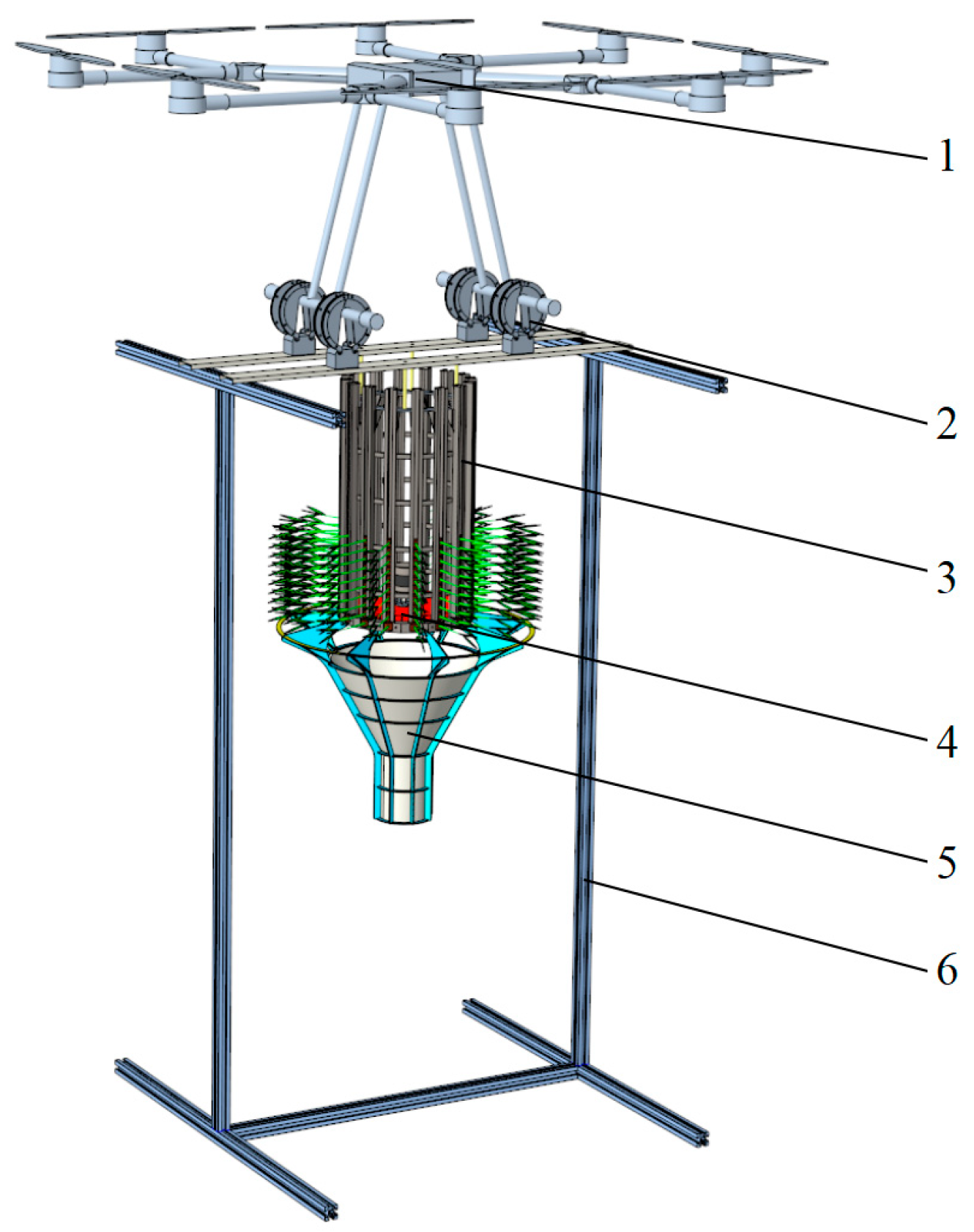
Figure 1. Overall structure of UAV transplanting system: 1. unmanned aerial vehicle; 2. connection mechanism; 3. seedling carrying box; 4. seedling pushing mechanism; 5. seedling guiding device; 6. docking frame.
Agriculture 14 00847 g001
Figure 2. Process of planting seedlings.
Agriculture 14 00847 g002
Figure 3. Rice seedling carrying and connection system.
Agriculture 14 00847 g003
Figure 4. Composition of the Pushing Seedling Institution section: 1. seedling pushing chassis; 2. push rod; 3. connecting rod; 4. disk; 5. follower crankshaft; 6. slide; 7. primary crankshaft; 8. motor base.
Agriculture 14 00847 g004
Figure 5. Sketch of the actuating end mechanism of the rice-pushing mechanism.
Agriculture 14 00847 g005
Figure 6. Timing diagram of pushing rice planting movement: (a) different timing positions for the same putter; (b) position interpretation; (c) same timing position for different putters.
Agriculture 14 00847 g006
Figure 7. Seedling Guiding Device.
Agriculture 14 00847 g007
Figure 8. Test stand.
Agriculture 14 00847 g008
Figure 9. Response surface analysis: (a) response surface of the spacing pass rate under different working speeds and bottom diameters of the seedling guide tube; (b) response surface of the uprightness pass rate under different throwing heights and bottom diameters of the seedling guide tube.
Agriculture 14 00847 g009
Figure 10. Test procedure: (a) disengagement from the docking frame; (b) flight toward the operating area; (c) transplanting effectiveness.
Agriculture 14 00847 g010
Table 1. Factor and level design.
LevelHeight X1/cmWorking Speed X2 (r/min)Diameter X3/mm
−11204540
01406050
11607560
Table 2. Test results.
Test NumberX1X2X3Spacing Pass Rate Y1/%Uprightness Pass Rate Y2/%
111180.682.2
21−1086.683.2
3−11083.885.3
401088.488.2
501−186.186.2
6−11182.283.7
7−1−1087.885.6
801087.687.2
901178.883.1
1011084.282.8
1101088.287.8
120−1−186.787.4
1301088.287.4
1411−185.885.2
15−11−186.886.2
160−1181.783.4
1701087.288.6
Table 3. Analysis of variance for the qualified rates of plant spacing and seedling uprightness.
Variance
Source
Degree of
Freedom
Sum of SquaresMean SquareF Valuep Value
Y1Y2Y1Y2Y1Y2Y1Y2
Model9135.4767.8715.057.5432.4721.7<0.00010.0003
X111.446.851.446.853.1219.70.12080.003
X2112.250.6112.250.6126.421.740.00130.2285
X3161.0519.8561.0519.85131.6857.12<0.00010.0001
X1X210.640.00250.640.00251.380.00720.27850.9348
X1X310.090.0630.090.0630.190.180.67280.6842
X2X311.320.21.320.22.850.580.13510.4701
X1213.3919.63.3919.67.3256.410.03040.0001
X2218.528.948.528.9418.3825.740.00360.0014
X32142.387.7642.387.7691.422.33<0.00010.0021
Residual73.252.430.460.35
Lack of fit32.241.120.750.372.961.140.16090.4346
Pure terror41.011.310.250.330.41
Cor total16138.7270.3
X1, X2, and X3 represent the levels of throwing height, working speed, and bottom diameter of the seedling guide tube, respectively. Y1 denotes the spacing pass rate, while Y2 represents the uprightness pass rate.
Disclaimer/Publisher’s Note: The statements, opinions and data contained in all publications are solely those of the individual author(s) and contributor(s) and not of MDPI and/or the editor(s). MDPI and/or the editor(s) disclaim responsibility for any injury to people or property resulting from any ideas, methods, instructions or products referred to in the content.