Article

Research on the Control Strategy of the Power Shift System of a Cotton Picker Based on a Fuzzy Algorithm

1
College of Mechanical and Electrical Engineering, Shihezi University, Shihezi 832003, China
2
Key Laboratory of Northwest Agricultural Equipment, Ministry of Agriculture and Rural Affairs, Shihezi 832003, China
3
Collaborative Innovation Center of Province-Ministry Co-Construction for Cotton Modernization Production Technology, Shihezi 832003, China
4
College of Information Science and Technology, Shihezi University, Shihezi 832003, China
*
Authors to whom correspondence should be addressed.
Agriculture 2024, 14(6), 874; https://doi.org/10.3390/agriculture14060874
Submission received: 25 April 2024 / Revised: 20 May 2024 / Accepted: 24 May 2024 / Published: 31 May 2024
(This article belongs to the Section Agricultural Technology)

Abstract

:
The control strategy of a power shift system has a significant impact on the driving stability and comfort of cotton pickers. To prevent the cotton picker from stopping to shift and reduce the jerks while shifting, in this study, the power shift system of a four-speed cotton picker was taken as the research object, and the working principles of the power shift transmission of the cotton picker and the hydrostatic transmission were analyzed. Firstly, the intelligent fuzzy control strategy of the variable pump and dual variable motor displacement of the cotton picker power shift system was designed using a fuzzy algorithm, and two-input and three-output fuzzy controllers were constructed with the engine rotational speed and vehicle speed as the input parameters, and the variable pump displacement, front motor displacement, and rear motor displacement as the outputs. Secondly, the model of the whole vehicle travel drive system of the cotton picker was constructed using co-simulation of Amesim and Simulink. Finally, the influence of the fuzzy shift control strategy and conventional manual shift method on the speed and driving distance of the cotton picker was compared and analyzed. The analysis results show that the fuzzy algorithm-based control strategy of the power shift system of the cotton picker can ensure that the cotton picker travels stably according to the target speed, and effectively reduces the speed fluctuation and jerks while shifting. The results of the study are of great significance to realize the non-stop shifting of the cotton picker as well as improve the stability and smoothness of the shift while driving.

1. Introduction

A PST (power shift transmission) can be used in the case of a load without interrupting the power output for gear switching, has a high transmission efficiency, does not cause the engine to stall due to a gear mismatch, and can reduce the impact and wear on the mechanical transmission parts caused by gear shifting [1,2]. The research and development of power shift transmissions can further promote the development of agricultural engineering vehicles, and then strongly promote the development of modern agriculture. The core of the powershift control system is the shift control strategy, and the advantages and disadvantages of the shift control strategy play a vital role in the stability and comfort of the vehicle.
To date, many scholars at home and abroad have conducted research on aspects related to the control strategy of the power shift transmission of engineering vehicles and achieved certain results. Among these, Xi et al. [3] designed a control strategy based on fixed shift overlap time, which not only improved the tractor productivity but also reduced the shift impact. Cai et al. [4] proposed a powerless interrupted shift strategy based on the coordinated control of the drive motor and wet clutch, which greatly reduced the impact, work of slipping, and shift time while shifting. Wu et al. [5] proposed an intelligent shift control strategy with an RBF neural network, and through a bench test of the loader’s automatic shifting intelligent test system, the feasibility of this method was verified. Zhang et al. [6] proposed a shift control strategy for transmissions based on fuzzy inference and verified that the proposed shift control strategy could improve the shift efficiency of the vehicle through simulation and a road test. Zhao et al. [7] proposed an adaptive shift control strategy to solve the problem of poor speed stability as well as the difficulty in controlling HMCVT transmissions. In terms of the smoothness of the power shift, Pan et al. [8] developed an automatic control strategy in Statechart and combined the PSO and genetic algorithms to create a particle swarm genetic algorithm, and confirmed the algorithm’s ability to enhance the transmission’s dynamic performance and shift smoothness. Li et al. [9] created a new type of power shift transmission, created a shift control method that included coordinated control of multiple clutches, and used simulation modeling to confirm the shift control technique’s efficacy. Shi et al. [10] proposed an adaptive control strategy for the torque phase and inertia phase based on the problem of consistency of shift quality in automatic transmissions, and the results showed that the proposed control strategy can improve the quality of the shifts. Jeoung et al. [11] proposed a speed prediction shifting strategy based on greedy control in order to improve the fuel efficiency of the vehicle, and the effectiveness of the proposed control strategy was verified through simulation analysis; results showed this strategy not only improved the fuel economy but also promoted drivability in a dynamic driving environment. Previous research [12,13,14,15] studied the application of the fuzzy logic algorithm to the transmission shifting strategy, which ensured the smoothness of vehicle traveling, could change in real time according to the vehicle operating parameters, and significantly improved the transmission shifting quality. Studies [16,17,18] have examined the transmission shift control strategy based on a genetic algorithm, which could effectively improve the transmission shift performance by controlling the clutch oil pressure and the speed at the shift point. Research [19,20,21,22] has studied shift control strategies combining a genetic algorithm and fuzzy theory; using a genetic algorithm to optimize the parameters of the fuzzy controller, this optimization method significantly improved the dynamic performance of the vehicle and achieved efficient and accurate shift operation.
The PST system of the cotton picker studied in this paper uses a pump-controlled motor as the power source. The front motor provides power input to the PST, which in turn transmits power from the transmission to the front axle, and the rear motor is directly installed on the rear reduction gearbox to provide power to the rear axle. This power transmission process depends on the hydrostatic volumetric speed control system composed of variable pumps and variable motors. The key to ensuring the stable operation of the whole system lies in the development of a reasonable gear shift strategy. Given the complexity of the hydrostatic transmission volumetric speed control system, in this study, a fuzzy algorithm-based control strategy was proposed. A fuzzy controller was designed that is capable of adaptively adjusting the displacement of the variable pump and the front and rear variable motors according to the real-time state of the vehicle and the demand for gear shifting. Additionally, this paper compares the effects of traditional manual gear shifting and the gear shifting strategy with a fuzzy algorithm on the performance of the cotton picker through simulation analysis. The simulation results show that the shifting strategy using a fuzzy algorithm can not only realize a cotton picker that does not need to stop to shift gears, but also significantly reduces the jerks while shifting gears, thus verifying the effectiveness of the fuzzy shifting control strategy.

2. Materials and Methods

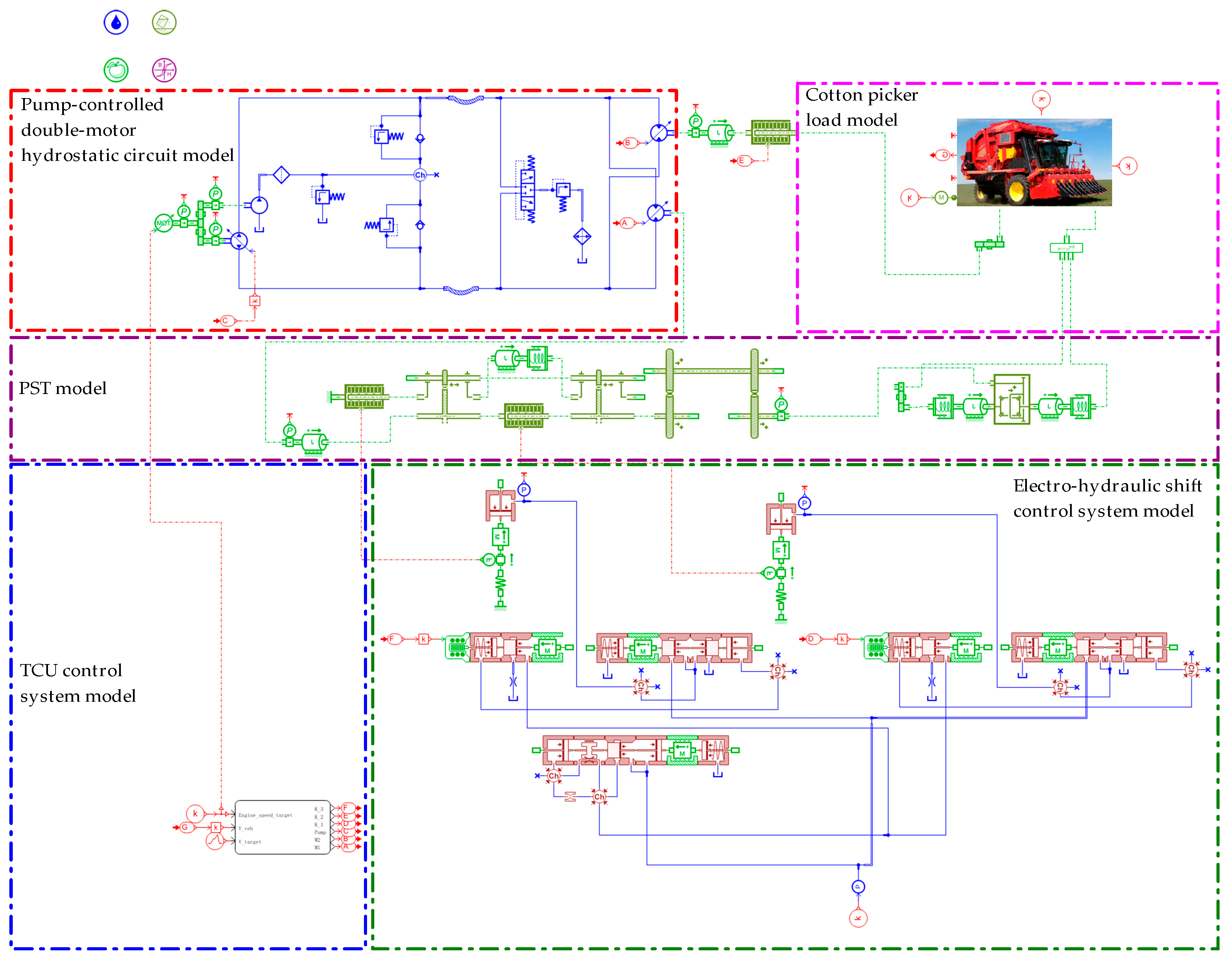
2.1. PST and Principle Analysis of Cotton Picker

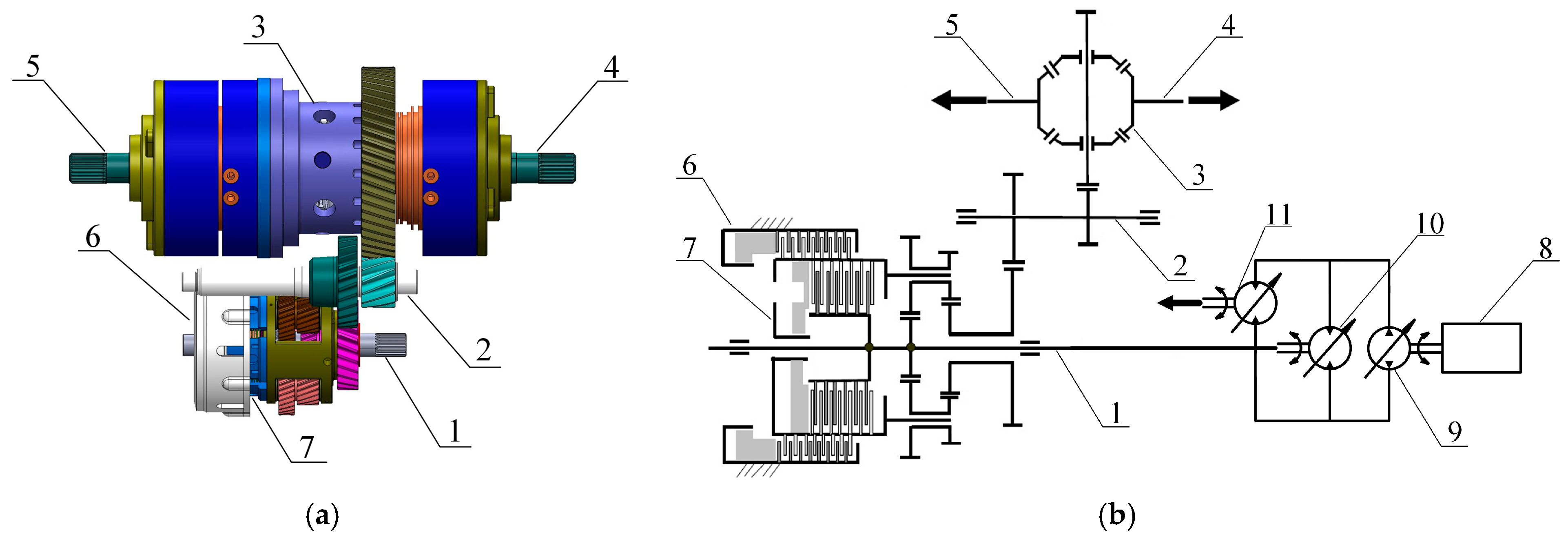
2.1.1. The Working Principle of PST

The cotton picker power shift system mainly consists of a variable displacement hydrostatic pump, two variable displacement motors, hydraulic components, and a PST, whose power is provided by the pump control motor. The structural model of the PST of the cotton picker is shown in Figure 1a, and the transmission structure is shown in Figure 1b. The PST consists of a power input shaft, intermediate shaft, differential, clutch, brake, and power output shaft. The transmission provides the cotton picker with two gears and four speeds, and the state of the transmission changes according to the different combined states of the brake and clutch. This enables the transmission to switch between different gears according to different driving needs and working conditions, and realize smooth shift operation by adjusting the combined state of the brake and clutch. The different working states of the transmission are shown in Table 1.
The cotton picker has four working speeds, i.e., the picking first gear, the picking second gear, the field transportation mode, and the road transportation mode. When the cotton picker is in the picking first gear, the picking second gear, or the field transportation mode, the brake is engaged and the clutch is separated, and the different working speeds are achieved by adjusting the variable pump and motor displacement. When the cotton picker is in the road transportation mode, the brake is separated and the clutch is engaged to achieve the switching between the low-speed gear and high-speed gear.

2.1.2. The Working Principle of Hydrostatic Transmission

The principle of the cotton picker variable pump and dual variable motor volumetric speed control system is shown in Figure 2. This mainly includes a hydrostatic traveling variable pump, check valve, relief valve, charge pump, reversing valve, and variable motor.
The variable pump and motor hydraulic transmission system can be represented as a flow-coupled system using the flow continuity equation [23]. Therefore, assuming that there is no flow loss in the hydraulic system, the variable pump output flow rate is equal to the variable motor input flow rate, which can be expressed by the following equation:
Q p = Q m
q p n p = q m n m
n m = q p q m n p
where Q p is the flow rate of the variable pump, L/min; Q m is the flow rate of the variable motor, L/min; q p is the displacement of the variable pump, mL/r; n p is the speed of the variable pump, r/min; q m is the displacement of the variable motor, mL/r; n m is the rotary speed of the variable motor, r/min.
From Equation (3), under the premise of a certain variable pump rotary speed, the variable motor rotary speed can be adjusted by changing the variable pump and variable motor displacement, and the adjustment process can be divided into two stages.
The first stage is the constant torque speed control stage, which is equivalent to variable pump-quantitative motor volumetric speed control. With the variable pump output rotary speed n p unchanged, and the variable motor displacement q m fixed at the maximum, the motor rotary speed n m is proportional to the variable pump displacement q p ; with the increase in the variable pump displacement q p , the motor rotary speed n m is gradually increased, as shown in Figure 3a. In the case of a certain variable pump pressure P , when the motor displacement q m is at its maximum, then the motor torque is a constant value, as shown in Figure 3b, and can be expressed by the following equation:
M m = P × q m max 2 π
The second stage is the constant power speed control stage, equivalent to the quantitative pump–variable motor volumetric speed control. With the variable pump output speed n p unchanged, when the variable pump displacement at the maximum q p max is fixed, the variable motor rotary speed n m is inversely proportional to the variable motor displacement q m ; when the variable motor displacement q m decreases, the motor rotary speed n m is gradually increased, as shown in Figure 3a. Since the variable pump displacement is at the maximum q p max , when the variable pump pressure P and rotary speed n p are certain, if the energy loss is ignored, the variable motor output power is equal to the variable pump input power, as shown in Figure 3b, which can be expressed by the following equation:
N = M m 2 π n m = P n p q p max

2.2. Simulation of the Power Shift Driving Transmission System of the Cotton Picker

2.2.1. Simulation Parameters of the Whole Vehicle Driving Transmission System of the Cotton Picker

The driving hydraulic module, the module of the PST, the hydraulic module of the PST, and the vehicle body module make up the cotton picker’s power shift driving transmission system. Table 2 displays the cotton picker’s main parameters.
According to the main parameters of the cotton picker, the power shift driving transmission system of the cotton picker was built in Amesim (2021) multidisciplinary simulation software.

2.2.2. Simulation Analysis of the Cotton Picker’s Picking Pattern

The cotton picker has different parameters in different picking modes, and the picking modes are divided into the picking first gear and the picking second gear. In the picking first gear mode, the maximum displacement of the variable pump is 85%, and the displacement of the front and rear variable motors remains unchanged at 100% displacement. In this configuration, the maximum operating speed of the cotton picker is set to 7.1 km/h. In the picking second gear mode, the maximum displacement of the variable pump is 100%, and its displacement is gradually increased from 0 to 100%, while the displacement of the variable motor is also kept at 100%. In this mode, the maximum operating speed of the cotton picker is 8.5 km/h. In the picking mode, the low-speed brake of the PST is in the engaged state, and the high-speed clutch is in the separated state. At this time, the speed control circuit presents the constant torque speed control characteristics, so the cotton picker can provide a high-torque output in low-speed operation, which is equivalent to the variable pump–quantitative motor speed control circuit. The curves of the speed and traveling distance of the cotton picker in the picking first gear and the picking second gear are shown in Figure 4.
From Figure 4, it can be seen that the speed of the cotton picker can reach the set value of 7.1 km/h stably in the picking first gear, and the traveling distance is 73 m in 40 s, while the speed can reach the set value of 8.5 km/h stably in the picking second gear, and the corresponding traveling distance is 86 m in 40 s.

2.2.3. Simulation Analysis of Cotton Picker Transportation Mode

The transportation modes of the cotton picker are divided into the field transportation mode and the road transportation mode. In the field transportation mode, the displacement of the variable pump is fixed at 100%, while the displacement of the front and rear variable motors gradually decreases from 100%. In this configuration, the maximum speed of the cotton picker is set to 14.5 km/h; in road transportation mode, the maximum set speed is further increased to 27.4 km/h. When switching from the field transportation mode to the road transportation mode, the low-speed brake of the PST changes from the engaged state to the separated state, while the high-speed clutch changes from the separated state to the engaged state. This results in a constant power speed control characteristic in the speed control circuit. Therefore, the cotton picker can provide low-torque output during high-speed operation, equivalent to a quantitative pump–variable motor speed regulation circuit. The speed and distance curves of the cotton picker in the field transportation mode and the road transportation mode are shown in Figure 5.
According to the data shown in Figure 5a, the speed of the cotton picker in the field transportation mode can reach the set value of 14.5 km/h stably, and the driving distance in 40 s is 130 m, while in the road transportation mode, the speed can reach the set value of 27.4 km/h, and the corresponding driving distance in 40 s is 453 m. According to Figure 5a, which shows the curve of the cotton picker’s speed during field transportation, the cotton picker’s speed fluctuates when it transitions from the picking gear to the field transportation gear; when the variable pump’s displacement reaches 100% of its maximum displacement, the variable motor’s speed reaches the transition speed, and the process of speed regulation changes from constant torque speed regulation to constant power speed regulation. Meanwhile, Figure 5b shows the speed fluctuation caused by the switching between the low-speed brake and the high-speed clutch.
Figure 6 shows the output torque curve of the front and rear variable motors of the cotton picker in road transportation mode. It can be seen that during the starting stage of the cotton picker, the output torque of the front and rear variable motors fluctuates for a certain time, with a fluctuation time of about 7.3 s. During the process of switching from picking mode to field transportation mode, and from field transportation mode to road transportation mode, the output torque values of the front and rear variable motors fluctuate greatly, which is also the reason for the speed fluctuation during the shifting process of the cotton picker.

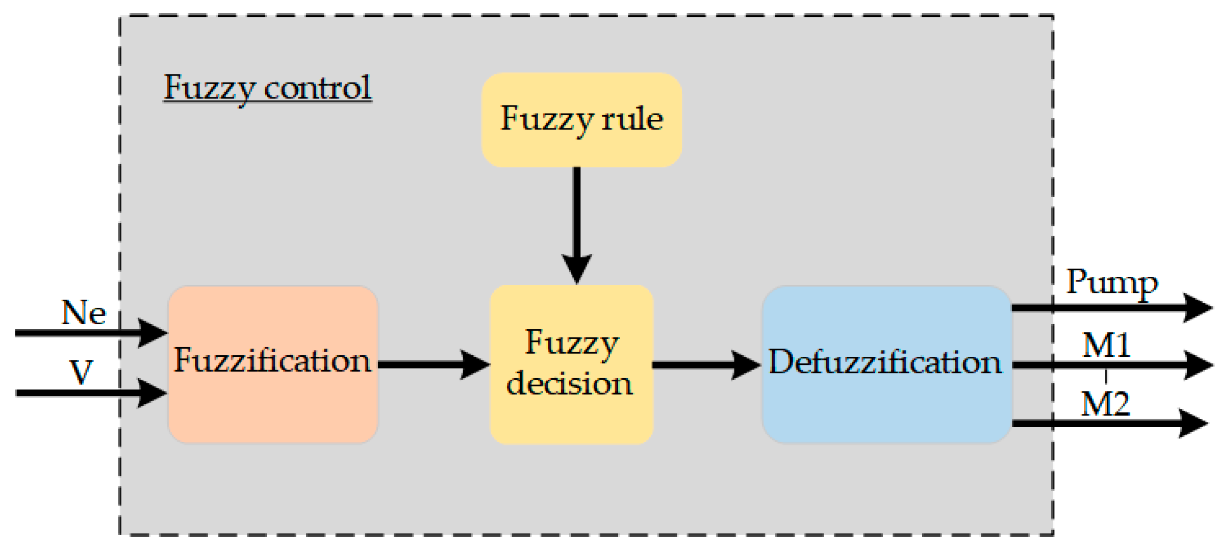
2.3. Fuzzy Shift Control Strategy

Fuzzy control is constructed based on expert knowledge; it does not rely on a precisely controlled model but provides a complex control system through certain fuzzy rules, and is a form of nonlinear intelligent control [24]. Since the displacement output of the variable pump and variable motor is discrete, it is difficult to express its control relationship by a continuous function. To realize the real-time online dynamic adjustment of the variable pump and dual variable motor, an automatic control method based on fuzzy theory was proposed and an intelligent shifting strategy was designed that intelligently controls the displacement of the variable pump and dual variable motor in the power shifting system of a cotton picker.
The schematic diagram of the designed fuzzy controller is shown in Figure 7.
The fuzzy shifting principle of the power shift system is to take the collected engine speed and vehicle speed as input parameters, and output the variable pump displacement, front motor displacement, and rear motor displacement through a series of fuzzy rules and fuzzy reasoning processes. This fuzzy control system is a dual-input and three-output system.

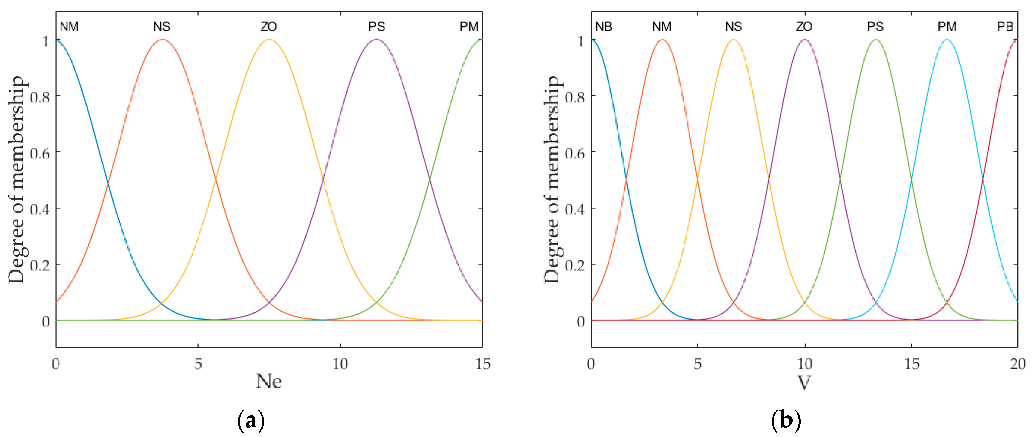
2.3.1. Fuzzification

In this paper, Ne (engine speed) is divided into five fuzzy sets, i.e., “Negative Medium” (NM), “Negative Small” (NS), “Zero” (ZO), “Positive Small” (PS), “Positive Medium” (PM); V (vehicle speed) is divided into seven fuzzy sets as follows: “Negative Big” (NB), “Negative Medium” (NM), “Negative Small” (NS), “Zero” (ZO), “Positive Small” (PS), “Positive Medium” (PM), “Positive Big” (PB); Pump (variable pump displacement) is divided into seven fuzzy sets of “Negative Big” (NB), “Negative Medium” (NM), “Negative Small” (NS), “Zero” (ZO), “Positive Small” (PS), “Positive Medium” (PM), “Positive Big” (PB); M1 (displacement of the front variable motor) is divided into seven fuzzy sets of “Negative Big” (NB), “Negative Medium” (NM), “Negative Small” (NS), “Zero” (ZO), “Positive Small” (PS), “Positive Medium” (PM), “Positive Big” (PB); and M2 (displacement of the rear variable motor) is divided into seven fuzzy sets of “Negative Big” (NB), “Negative Medium” (NM), “Negative Small” (NS), “Zero” (ZO), “Positive Small” (PS), “Positive Medium” (PM), and “Positive Big” (PB). Usually, fuzzy subsets cover the fuzzy domain better when the total number of fuzzy domain elements is two to three times the total number of fuzzy subsets [13], so the fuzzy domain of Ne is set to (0, 15), the fuzzy domain of V is set to (0, 20), the fuzzy domain of Pump is set to (0, 20), the fuzzy domain of M1 is set to (0, 20), and the fuzzy domain of M2 is set to (0, 20). According to the requirements of the test data, the variation interval of Ne is [400, 2100], the variation interval of V is [0, 28], the variation interval of Pump is [0, 100%], the variation interval of M1 is [0, 100%], and the variation interval of M2 is [0, 100%].

2.3.2. The Definition of the Input and Output Affiliation Functions

The affiliation function is used to quantitatively describe fuzzy concepts, and a suitable affiliation function is the basis for solving practical problems using fuzzy set theory. The degree of affiliation of a fuzzy set is defined as follows:
A = u μ A ( u ) / u
where A is a fuzzy set and μ is the degree to which the domain element u belongs to the set A .
The normal-type fuzzy distribution is the dominant and most common one, and its basic form is [25]:
μ ( x ) = e ( x a b ) 2 , b > 0
where a is the center of the affiliation function of the fuzzy set and b is the width of the affiliation function of the fuzzy subset.
The affiliation functions of Ne, V, Pump, M1, and M2 are selected as Gaussian affiliation functions The local area control characteristics are relatively sensitive and the corresponding affiliation functions are denser. The input and output affiliation functions of the fuzzy controller are shown in Figure 8.

2.3.3. Establishment of Fuzzy Control Rules

Fuzzy control rules are the core part of fuzzy control. These rules define the logical relationship between state variables and control variables, and are mainly based on semantic descriptions rather than purely numerical relationships. Fuzzy rules are formulated based on the accumulation of experience from skilled drivers. Thirty-five fuzzy control rules were developed by examining the fuzzy subsets of input and output variables. As indicated in Table 3, Table 4 and Table 5, respectively, the control rules for variable pump displacement, and front and rear variable motor displacement, can be produced using the fuzzy inference method.
According to the fuzzy control classical Mamdani algorithm, the displacement control rule for the variable pump and variable motor can be expressed as:
IF   Ne = A i   AND   V = B j   THEN   Pump = C i j
Then the fuzzy relationship can be expressed as:
R k = A i × B j × C i j ( i = 1 , 2 , , 5 ; j = 1 , 2 , , 7 ; k = 1 , 2 , 35 )
where A i , B j , C i j is the fuzzy subset corresponding to Ne, V, and Pump, respectively.
The total fuzzy relationship is:
R = U K R K = U i , j A i × B i × C i j
The process of fuzzy logic reasoning by calculating the fuzzy quantities of R , as well as the two input variables of the fuzzy controller, and then finding the fuzzy set U m n of the output variables over the domain of the argument, can be expressed by the following equation:
U m n = ( A i , B j ) R
where “ ” stands for synthetic operation symbols.
Ne and V with Pump, M1, and M2 fuzzy inference output surfaces are shown in Figure 9.
From the fuzzy reasoning output surface of the variable pump, front variable motor, and rear variable motor displacement, it can be seen that the output of the variable pump, front variable motor, and rear variable motor displacement is clear without an overlapping phenomenon, which indicates that the fuzzy controller design is reasonable.

2.3.4. Defuzzification

The result obtained from fuzzy reasoning is a fuzzy quantity; however, the actual actuator needs specific numerical values to operate. Therefore, the fuzzy quantity needs to be converted into an exact quantity, and this conversion process adopts the center of gravity method to complete the defuzzification processing [26]. The specific mathematical expressions are as follows:
Z = i = 1 n u c ( Z i ) Z i i = 1 n u c ( Z i )
where u c ( Z i ) is the affiliation function output value, Z i is the state corresponding to the output value, and n is the number of states.

3. Simulation Verification of the Automatic Gear Shift Strategy and Discussion of Results

Co-simulation with Amesim (2021) and Simulink (2017) software was used to simulate the automatic shifting process of the PST of the cotton picker. Amesim software was used to build a model of the whole vehicle driving transmission system, while Simulink was used to build a model of the fuzzy shift control strategy. Figure 10 presents a co-simulation model of the variable displacement pump and dual variable motor with fuzzy control, including a fuzzy logic control module, an Amesim interface module, and a Stateflow interface module. Figure 11 shows the control logic for brake and clutch actions developed in Stateflow.
In the fuzzy control co-simulation model of variable pump and dual-variable motor displacement, the engine speed and vehicle speed are used as the input parameters of the fuzzy controller, and the output of the fuzzy controller is the displacement values of the variable pump, the front variable motor, and the rear variable motor. The gear switching of the cotton picker is determined by the control logic of the brake and the clutch action formulated in Stateflow, and the signals of the low-speed brake and the high-speed clutch are determined by the actual vehicle speed, with the clutch K_2 always in the engaged state. When the cotton picker is in the low-speed driving mode, the low-speed brake K_3 is engaged and the high-speed clutch K_1 is separated; when the actual vehicle speed V is faster than threshold_2, the high-speed clutch K_1 is engaged and the low-speed brake K_3 is separated, with the cotton picker switching from the low-speed gear to the high-speed gear.
The Amesim–Simulink co-simulation model of the whole vehicle driving transmission system for the cotton picker is shown in Figure 12. The system mainly includes the following parts: the pump-controlled dual-motor hydrostatic circuit model, the TCU (Transmission Control Unit) control system model, the PST model, the electro-hydraulic shift control system model, and the cotton picker load model. The pump-controlled dual-motor hydrostatic circuit model adjusts the displacement and flow distribution of the pump and dual motors in the hydraulic system to control the driving speed and direction of the cotton picker, ensuring smooth and controllable driving in different terrains and working conditions. The TCU control system model is responsible for intelligent control and regulation of the transmission, precisely controlling clutch engagement and disengagement, meshing speed, and transmitted torque [27], and automatically determining the optimal shift timing based on workload, speed, and engine speed parameters to optimize the driving performance, maneuverability, and stability of the cotton picker. The PST model adjusts different gears and transmission ratios in a timely manner under various working conditions to ensure the cotton picker can achieve the best power transmission efficiency according to actual driving needs and economic performance requirements. The electro-hydraulic shift control system model precisely controls the actions of the hydraulic system to achieve smooth and rapid gear shifting. The cotton picker load model is used to simulate the vehicle parameters and environmental parameters of the whole cotton picker, analyzing the dynamic behavior and performance of the cotton picker during the picking process.
Based on the Amesim–Simulink model of the whole vehicle driving transmission system of the cotton picker and the designed shift strategy model, the automatic shifting performance of the cotton picker was simulated, and the different effects of the fuzzy gearshift control strategy and the traditional gearshift method on the driving speed of the cotton picker were compared. In the road transportation mode, the initial engine speed was set to 1900 r/min and the target speed was set to 27.4 km/h. The simulation time was set to 100 s and the simulation step size was set to 0.01 s. Figure 13 shows the comparison curve of the road transportation mode speed of the cotton picker using the automatic shifting control strategy and manual shift control. From Figure 13, it can be seen that using the automatic shifting control strategy can ensure that the cotton picker stably maintains the target speed, significantly reducing speed fluctuations and jerks during the shifting process. This is because the automatic shifting control strategy can adjust parameters in real-time based on the current state and load of the vehicle, providing a smoother acceleration and deceleration process, and avoiding the problems of untimely shifting and decreased speed during manual shifting. Figure 14 shows the traveling distances in the road transportation mode under the two shifting modes of the automatic shifting control strategy and manual shifting. The results show that in the same traveling time, the distance traveled by the cotton picker with the automatic shifting strategy is 669 m, while the distance traveled with manual shifting is 605 m, and the distance traveled under the automatic shifting strategy is 64 m more than that of manual shifting.
Figure 15 shows the comparison of the low-speed brake and high-speed clutch control signals during manual shifting and automatic shifting in the road transportation mode. As shown in Figure 15a, during manual shifting, the low-speed brake is switched from the engaged state to the separated state, while the high-speed clutch is switched from the separated state to the engaged state, and this switching is direct switching without a transition phase. In the automatic shifting process, as shown in Figure 15b, the low-speed brake and high-speed clutch control signals for the transition engagement overlap. Referring to Figure 13, which shows the speed curves for automatic and manual gear shifting of the cotton picker, it can be observed that when using manual shifting, the vehicle speed decreases due to the direct engagement of the low-speed brake and high-speed clutch. However, when using automatic shifting, the speed curve is smoother because of the transitional overlapping engagement of the low-speed brake and high-speed clutch.
Figure 16 shows the flow rate curves of the front and rear variable motors when using the automatic shifting control strategy. From Figure 16, it can be observed that during the startup phase of the cotton picker, there is a brief fluctuation in the flow rate of both the front and rear motors, but the duration of the fluctuation is short, around 0.7 s. As the speed gradually increases, the flow rate of the front motor increases to a certain extent, while the rear motor correspondingly decreases. This is because the flow rate of the front and rear motors will automatically adjust accordingly with the adjustment of pump displacement. When the speed of the cotton picker reaches 8.5 km/h, the flow rate of the front motor begins to decrease, and the flow rate of the rear motor gradually increases. At 10.52 s, the cotton picker shifts from low gear to high gear, and at this time, both the front and rear motor flow rates experience some fluctuations. When the cotton picker reaches its top speed, the flow rates of both the front and rear motors gradually stabilize at constant values, which are 189 L/min and 181 L/min, respectively, because as the pump displacement is adjusted, the flow rate of the front and rear motors will automatically stabilize at the required value.
Figure 17 shows the output rotary speed variation curves of the front and rear motors of the cotton picker in road transportation mode. It can be observed that there is a small fluctuation in the output rotary speed of the front and rear motors at the startup of the cotton picker, with a fluctuation time of about 0.8 s. Subsequently, the rotary speed of the front motor gradually increases, because when the flow rate of the front motor decreases, the rotary speed of the front motor briefly increases, while the speed of the rear motor gradually decreases. At 10.52 s, as the cotton picker shifts gears, the rotary speed of the front motor gradually decreases, and the rotary speed of the rear motor gradually increases. When the cotton picker reaches its top speed, the output rotary speeds of the front and rear motors stabilize at certain values, which are 1038 r/min and 1566 r/min, respectively. Figure 18 shows the output torque curves of the front and rear variable motors. The torque fluctuation of the front and rear variable motors at startup is small, with a fluctuation time of about 0.9 s. When operating at low speed, the front motor torque stabilizes at 783.8 N·m, and the rear motor torque stabilizes at 498.8 N·m, meeting the requirement of low-speed and high-torque operation of the cotton picker. During the transition from low gear to high gear, there is a brief fluctuation in the torque of the front and rear motors, after which the front motor torque stabilizes at 325 N·m and the rear motor torque stabilizes at 207 N·m.
By comparing the output torque curves of the front and rear variable motors of the cotton picker in road transportation mode without the fuzzy shift control strategy, as shown in Figure 6, it can be seen that in road transportation mode, the adoption of the fuzzy shift control strategy can effectively reduce the front and rear motor torque fluctuation times of the cotton picker at the start stage, reducing the torque fluctuation time from 7.3 s to 0.9 s. The torque fluctuation of the motor at the shift point of the cotton picker is reduced, which further verifies the effectiveness of the fuzzy shift control strategy of the cotton picker.

4. Conclusions

In this study, the power shift system of a four-speed cotton picker was taken as the research object, and the power shift control strategy of the cotton picker was studied. A Amesim–Simulink co-simulation model of the whole vehicle driving transmission system of the cotton picker was established. This model uses fuzzy logic control theory to intelligently control the variable pump and dual variable motor displacement of the power shifting system of the cotton picker, thereby achieving the shifting requirements of the power shifting system of the cotton picker. The following conclusions have been drawn from this study:
(1)
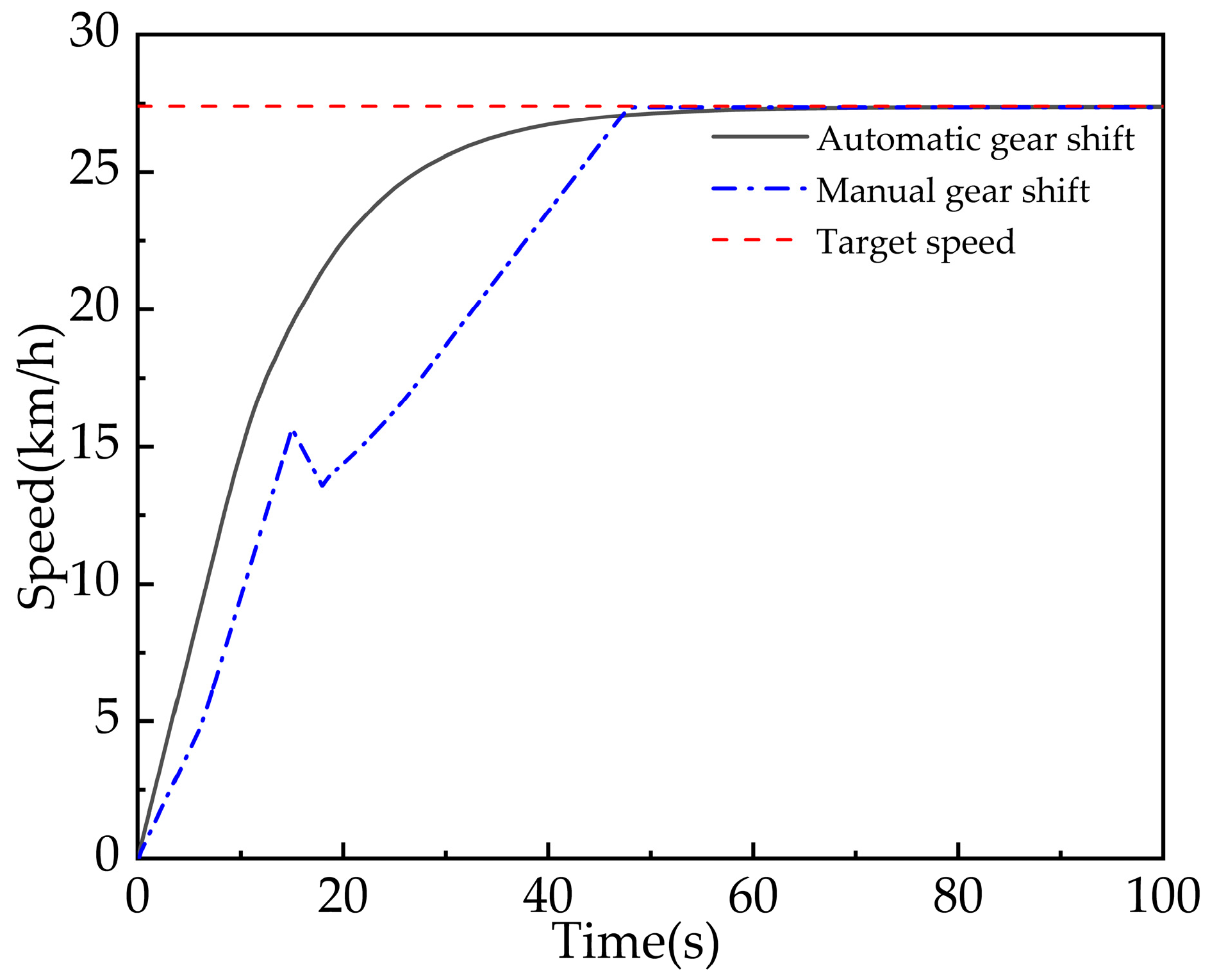
In order to reduce the speed fluctuation and the jerking in the process of cotton picker shifting, this study firstly analyzed the working principle of the PST and hydrostatic transmission, proposed a fuzzy shifting control strategy, and compared the effects of the fuzzy shifting control strategy and the traditional shifting method on the speed of the cotton picker. When the fuzzy shift control strategy is used, the speed fluctuation and jerking of the cotton picker are significantly reduced.
(2)
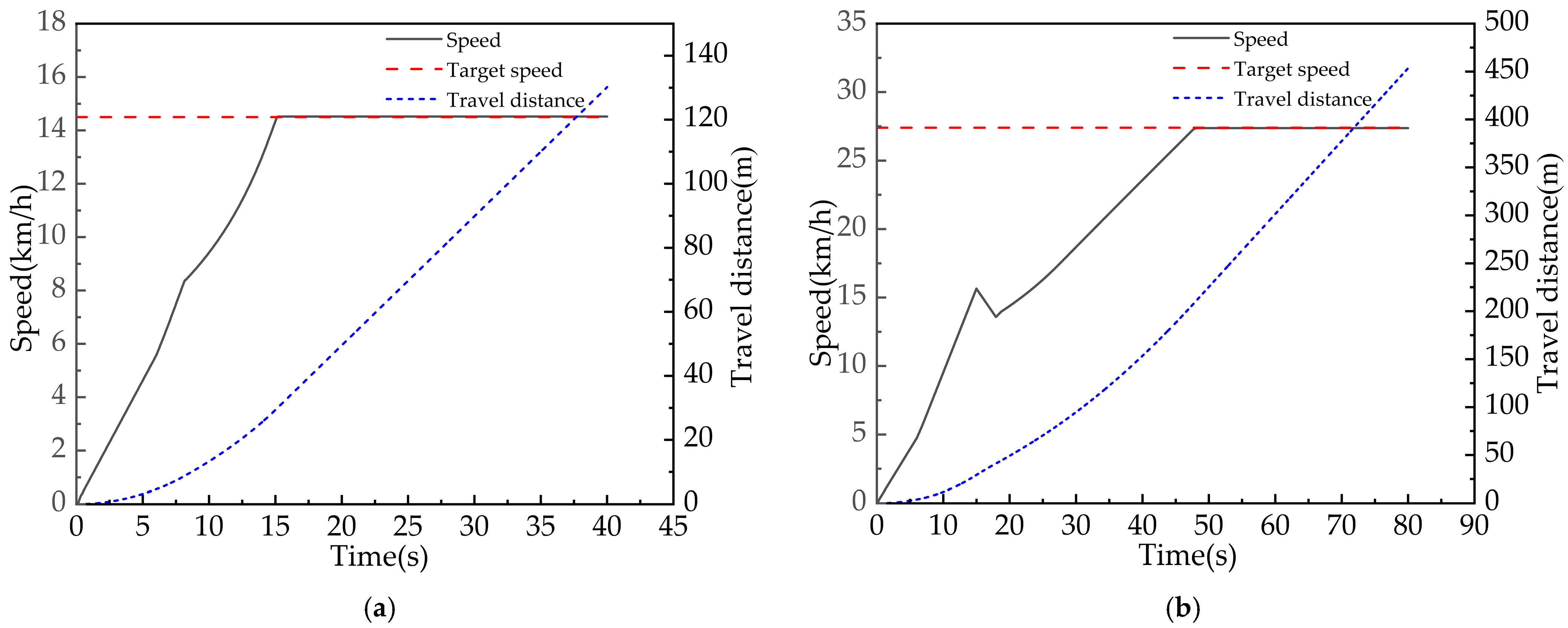
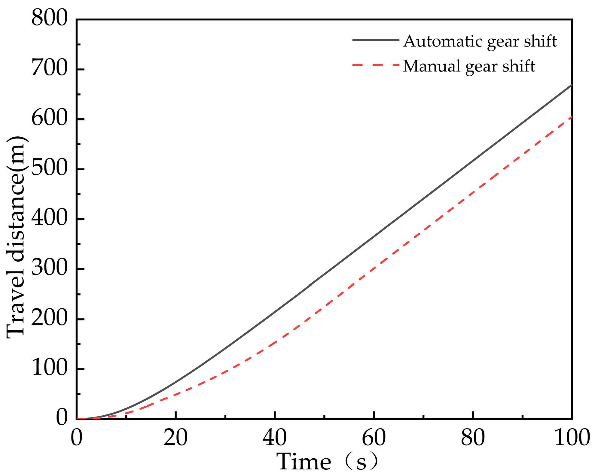
When the automatic gearshift strategy with fuzzy control theory is adopted, the low-speed brake and high-speed clutch are engaged in a transitional overlapping engagement, which makes the speed curve smoother compared with the direct engagement of the traditional manual gearshift; in the same driving time, the automatic gearshift strategy with the application of fuzzy logic can make the cotton picker travel 64 m more compared to using the traditional manual gearshift.
(3)
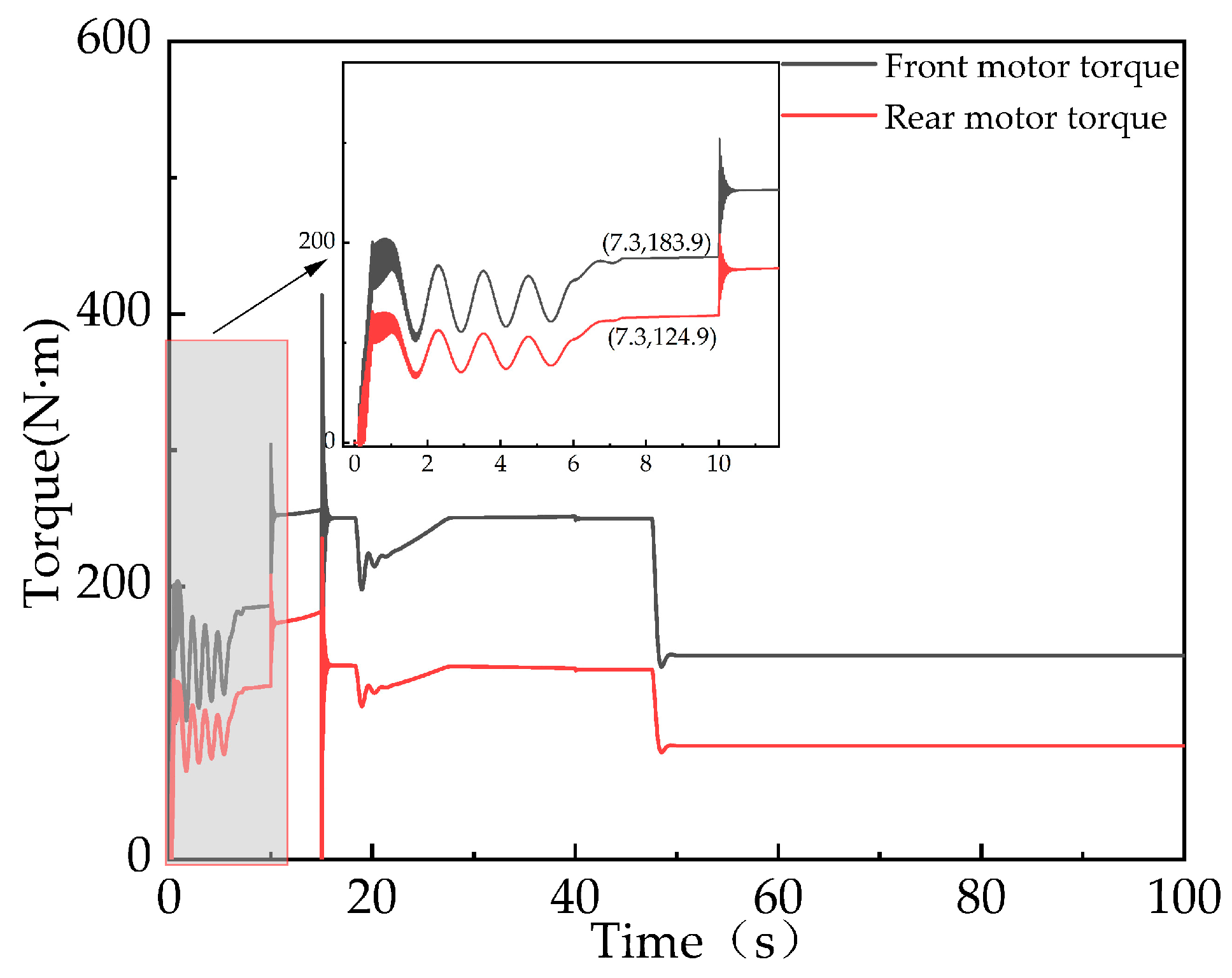
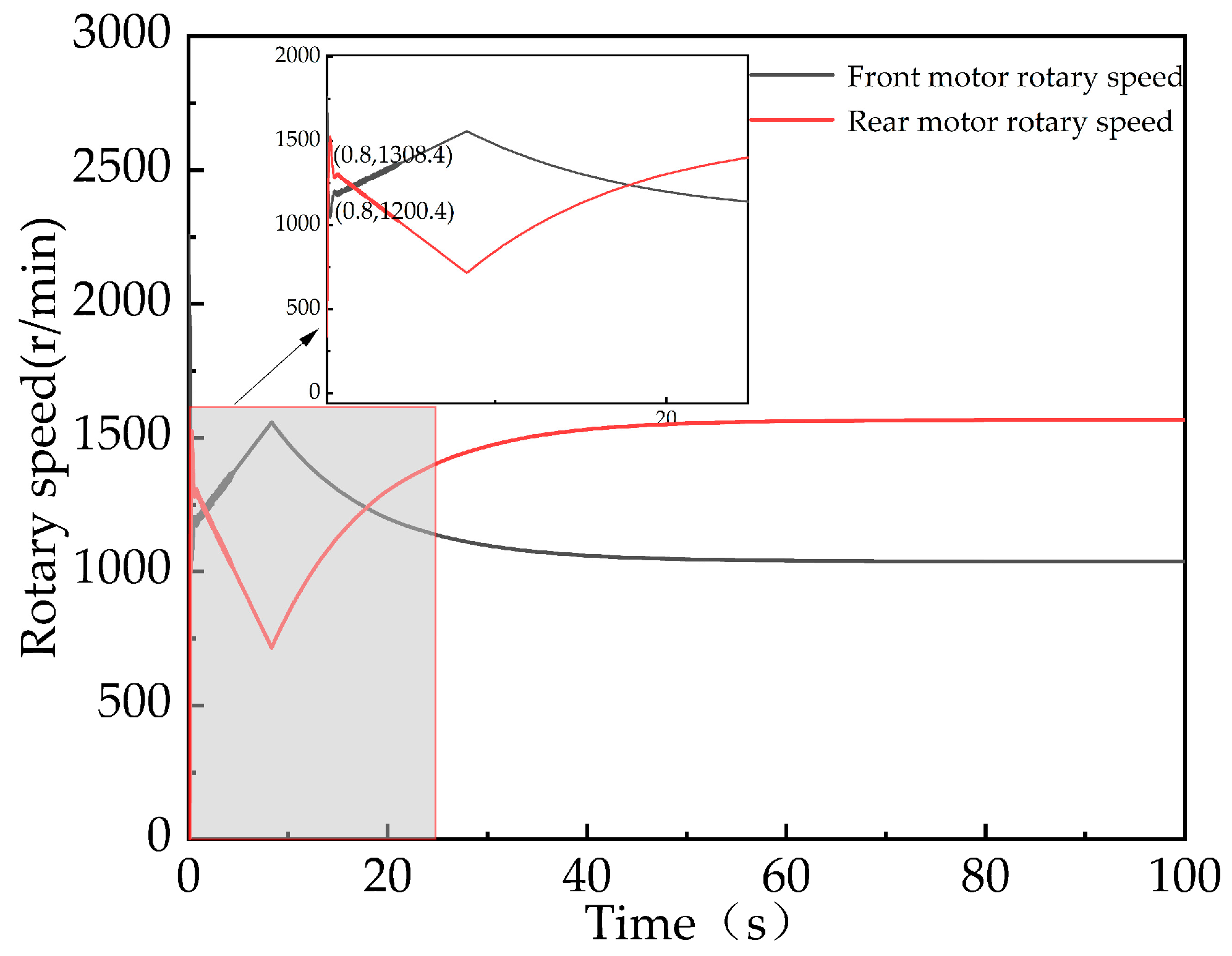
By analyzing the front and rear variable motor flow, rotary speed, and torque magnitude of the cotton picker under the fuzzy shift control theory, it was found that the front and rear variable motor flow, rotary speed, and torque of the cotton picker fluctuates to a certain extent at the time of startup, but the fluctuation time is very short. By comparing the output torque curves of the front and rear variable motors of the cotton picker in road transportation mode with and without the fuzzy shift control strategy, it was found that the torque fluctuation time of the front and rear motors during the startup phase decreased from 7.3 s to 0.9 s, and the torque fluctuation at the shift points was significantly reduced. This indicates that the fuzzy shift control strategy has good dynamic response performance and stability.

Author Contributions

Conceptualization, X.M., X.N. and W.C.; methodology, X.M.; software, X.M.; validation, W.P., H.C., W.C. and Y.Z.; formal analysis, X.N. and W.C.; investigation, X.M.; resources, B.Z.; data curation, X.M. and H.C.; writing—original draft preparation, X.M.; writing—review and editing, X.M.; visualization, B.Z. and W.P.; supervision, Y.Z.; project administration, X.N. and W.C; funding acquisition, X.N. All authors have read and agreed to the published version of the manuscript.

Funding

This research was funded by National Natural Science Foundation of China, grant number 51665051 and Xinjiang Production and Construction Corps financial science and technology projects major science and technology projects “Unveiling the List and Taking command”, grant number 2022AA001.

Institutional Review Board Statement

Not applicable.

Data Availability Statement

All relevant data presented in the article are kept at the request of the institution and are therefore not available online. However, all data used in this manuscript are available from the corresponding authors.

Conflicts of Interest

The authors declare no conflicts of interest.

References

  1. Liu, J.Z.; Zhao, Z.M.; Li, B. Research Status and Development Trend of Tractor Power Shift Transmission Technology. Tract. Farm Transp. 2023, 50, 10–14. [Google Scholar]
  2. Du, W.; Zhao, S.D.; Gao, J.Z.; Zheng, Z.h. Research Status and Development Trend of Tractor Power Shift Technology. Automob. Appl. Technol. 2020, 3, 216–219. [Google Scholar]
  3. Xi, Z.Q.; Zhou, Z.L.; Zhang, M.Z.; Cao, Q.M. Shift Characteristics and Control Strategy of Powershift Transmission on Tractor. Trans. Chin. Soc. Agric. Mach. 2016, 47, 350–357. [Google Scholar]
  4. Cai, S.L.; Chen, Q.H.; Lin, T.L.; Ren, H.L.; Fu, S.J.; Xu, M.K. Power Uninterrupted Shift Strategy of Electric Loader Based on CoordinateddControl of Drive Motor and Wet Clutch. J. Mech. Eng. 2022, 58, 46–56. [Google Scholar]
  5. Wu, G.; Ma, W.; You, L. Research on Intelligent Shift Control Strategy of The Loader Based on Radial Basis Function Neural Network. J. Phys. Conf. Ser. 2020, 1550, 062003. [Google Scholar] [CrossRef]
  6. Zhang, L.P.; Zhang, H.X.; Han, Z.Q.; Chen, J.Y.; Liu, J.C. A novel multi-parameter coordinated shift control strategy for an automated manual transmission based on fuzzy inference. Proc. Inst. Mech. Eng. Part D J. Automob. Eng. 2017, 231, 684–699. [Google Scholar] [CrossRef]
  7. Zhao, X.; Ni, X.D.; Wang, Q.; Bao, M.X.; Li, S.; Han, S.M. Research on adaptive control strategy of hydraulic mechanical continuously variable transmission of a cotton picker. Proc. Inst. Mech. Eng. Part C J. Mech. Eng. Sci. 2020, 234, 3335–3345. [Google Scholar] [CrossRef]
  8. Pan, W.L.; Wang, L.; Ni, X.D.; Cai, W.Q.; Zhao, Y.Q.; Chen, H.J.; Lin, Y.G.; Zhou, Y.H. Optimisation of Control Strategies for Power Shift Gearboxes. Agriculture 2023, 13, 1266. [Google Scholar] [CrossRef]
  9. Li, B.G.; Sun, D.Y.; Hu, M.H.; Zhou, X.Y.; Liu, J.L.; Wang, D.Y. Coordinated Control of Gear Shifting Process with Multiple Clutches for Power-Shift Transmission. Mech. Mach. Theory 2019, 140, 274–291. [Google Scholar] [CrossRef]
  10. Shi, G.; Dong, P.; Sun, H.Q.; Liu, Y.; Cheng, Y.J.; Xu, X.Y. Adaptive control of the shifting process in automatic transmissions. Int. J. Automot. Technol. 2017, 18, 179–194. [Google Scholar] [CrossRef]
  11. Jeoung, D.; Min, K.; Sunwoo, M. Automatic Transmission Shift Strategy Based on Greedy Algorithm Using Predicted Velocity. Int. J. Automot. Technol. 2020, 21, 159–168. [Google Scholar] [CrossRef]
  12. Cao, Q.M.; Zhou, Z.L.; Zhang, M.Z. Fuzzy Adaptive Shift Schedule of Tractor Subjected to Random Load. Math. Probl. Eng. 2017, 2017, 9284281. [Google Scholar] [CrossRef]
  13. Zhou, Z.L.; Xing, M.X.; Xu, L.Y.; Ding, J.Q.; Zhao, Y.K. Simulation Analysis of Tractor AMT Shifting Process Based on Fuzzy Optimization of Downshifting. Adv. Mater. Res. 2012, 1670, 970–975. [Google Scholar] [CrossRef]
  14. Zhao, K.G.; Chang, H.; Hu, Y.L.; Yao, W.H. Study on Uninterrupted Shift Transmission Shift Strategy Based on Fuzzy Control. Adv. Mater. Res. 2013, 2649, 668–671. [Google Scholar] [CrossRef]
  15. Ning, M.; Hou, B.J.; Wang, Y.X.; Ren, K.; Chen, S.X.; Wang, P.; Lin, R.F. Research on Optimal Shift Control Strategy of Two-speed AMT based on Fuzzy Control. J. Phys. Conf. Ser. 2020, 1575, 012116. [Google Scholar]
  16. Sun, D.Y.; Chen, X.D.; Li, B.G.; Yang, B. Dynamic control method of tractor powershift process based on genetic algorithm. J. Chongqing Univ. 2019, 42, 1–14. [Google Scholar]
  17. Song, Q.; Ye, S.D.; Li, W.C.; Gao, P.; Li, Y.T.; Huang, Y.S. Research on AMT Overall Shift Schedule for Pure Electric Vehicles Based on NSGA-II Algorithm. Chin. J. Automot. Eng. 2017, 7, 44–51. [Google Scholar]
  18. Zhang, Y.A.; Du, Y.F.; Meng, Q.F.; Li, X.Y.; Liu, L.; Zhu, Z.X. Model-free adaptive control of tractor wet clutch pressure based on improved genetic algorithm. J. Jilin Univ. Eng. Technol. Ed. 2023, accepted. [Google Scholar]
  19. Gao, Z.Y.; Du, M.G.; Li, S.L.; Li, J. Design of Shifting Rules of Automatic Transmission Based on Genetic Algorithm Optimization and Fuzzy Control Dynamic Optimization. Acta Armamentarii 2021, 42, 684–696. [Google Scholar]
  20. Wu, S.J.; Zhu, E.Y.; Zhang, P.Z.; She, J.J. Experimental study on fuzzy intelligent shifting control of vehicle using genetic Algorithm. Mach. Des. Manuf. 2009, 6, 34–36. [Google Scholar]
  21. Gao, Z.Y.; Du, M.G.; Li, S.L. Design and Optimization of Dynamic Shift Law for Hyclraulic Automatic Transmission. Veh. Power Technol. 2019, 1, 23–28. [Google Scholar]
  22. Wu, S.J.; Zhu, E.Y.; Li, Q.L.; Xie, J.; Peng, X. Study on intelligent shift control strategy of automobile based on genetic-fuzzy algorithm. In Proceedings of the 2008 3rd International Conference on Innovative Computing Information and Control, Dalian, China, 18–20 June 2008; p. 402. [Google Scholar]
  23. Wang, L.; Liu, X.H.; Wang, X.; Chen, J.S.; Liang, Y.J. Shifting strategy of digital hydraulic transmission system for wheel loader. J. Jilin Univ. Eng. Technol. Ed. 2017, 47, 819–826. [Google Scholar]
  24. Chu, Y.M.; Wu, H.C.; Zhao, L.M.; Cao, G. Heavy Hydraulic Automatic Transmission of Shift Research Based on Fuzzy Theory. Comput. Simul. 2019, 36, 137–143. [Google Scholar]
  25. Zhou, J.F.; Zheng, D.C.; Gao, R.; Leng, W. Calculation method of fuzzy reliability in combination of fuzzy variables and random variables. Eng. Mech. 2021, 38, 12–23. [Google Scholar]
  26. Bouzidi, M.; Harrouz, A.; Mansouri, S. Control and automation of Asynchronous motor using Fuzzy logic. SRM 2019, 1, 154–171. [Google Scholar] [CrossRef]
  27. Wu, Y.W.; Yan, X.H.; Zhou, Z.L. Architecture Modeling and Test of Tractor Power Shift Transmission. IEEE Access 2021, 9, 3517–3525. [Google Scholar]
Figure 1. Cotton picker powershift transmission structure model and transmission structure diagram. (a) Structural model diagram of powershift transmission; (b) powershift transmission drive diagram. In the figure, 1—input shaft; 2—intermediate shaft; 3—differential; 4, 5—power output shaft; 6—brake; 7—clutch; 8—engine; 9—variable displacement pump; 10—front variable motor; 11—rear variable motor.
Agriculture 14 00874 g001
Figure 2. Principle of the volumetric speed control system for a cotton picker with variable pumps and dual variable motors. In the figure, 1—variable pump; 2, 6—check valve; 3, 7, 8, 11—relief valve; 4—charge pump; 5, 9, 12—tank; 10—directional valve; 13—rear variable motor; 14—front variable motor.
Agriculture 14 00874 g002
Figure 3. Volumetric speed regulation characteristics of a variable pump and variable motor. (a) Variable motor variable speed characteristics; (b) variable motor output power and torque curves.
Agriculture 14 00874 g003
Figure 4. Cotton picker picking mode speed and travel distance. (a) Cotton picker picking first gear speed and traveling distance; (b) cotton picker picking second gear speed and traveling distance.
Agriculture 14 00874 g004
Figure 5. Vehicle speed and distance traveled curves for different transportation modes of the cotton picker. (a) The speed and distance curves of the cotton picker in the field transportation mode; (b) the speed and distance curves of the cotton picker in the road transportation mode.
Agriculture 14 00874 g005
Figure 6. The output torque curve of the front and rear variable motors of the cotton picker in road transportation mode.
Agriculture 14 00874 g006
Figure 7. Fuzzy controller schematic.
Agriculture 14 00874 g007
Figure 8. Controller input and output affinity function curves. (a) Ne affiliation function curve; (b) V affiliation function curve; (c) Pump affiliation function curve; (d) M1 affiliation function curve; (e) M2 affiliation function curve.
Agriculture 14 00874 g008aAgriculture 14 00874 g008b
Figure 9. Fuzzy reasoning output surface. (a) Pump fuzzy reasoning output surface; (b) M1 fuzzy reasoning output surface; (c) M2 fuzzy reasoning output surface.
Agriculture 14 00874 g009
Figure 10. Co-simulation model for fuzzy control of variable pump and dual variable motor displacement.
Agriculture 14 00874 g010
Figure 11. Brake and clutch action control logic.
Agriculture 14 00874 g011
Figure 12. Amesim–Simulink co-simulation model of the driving transmission system of the whole vehicle of the cotton picker with automatic gear shifting.
Agriculture 14 00874 g012
Figure 13. Automatic shifting control strategy and manual shift speed curves for the cotton picker.
Agriculture 14 00874 g013
Figure 14. Automatic shifting control strategy and manual shift travel distances for the cotton picker.
Agriculture 14 00874 g014
Figure 15. Manual shifting and automatic shifting low-speed brake and high-speed clutch control signals for road transportation. (a) Manual shifting brake and clutch control signals; (b) automatic shifting brake and clutch control signals.
Agriculture 14 00874 g015
Figure 16. Road transportation mode front and rear motor flow rates.
Agriculture 14 00874 g016
Figure 17. Road transportation mode front and rear motor output rotary speeds.
Agriculture 14 00874 g017
Figure 18. Front and rear variable motor output torque.
Agriculture 14 00874 g018
Table 1. Different working states of the PST.
Working StateBrakeClutch
Neutral gearseparationseparation
Low-speed gearengagementseparation
High-speed gearseparationengagement
Lockedengagementengagement
Table 2. Cotton picker main parameters.
Main ParametersValueMain ParametersValue
Cotton picker vehicle mass (kg)33,000Maximum displacement of the rear drive motor (mL/r)105
Front tire parameters520/85R42PST gear ratio2.38
Rear tire parameters620/75R34Picking first gear (km/h)0~7.1
Engine rated speed (r/min)1900Picking second gear (km/h)0~8.5
Maximum displacement of traveling variable pump (mL/r)210Field transportation (km/h)0~14.5
Maximum displacement of the front drive motor (mL/r)165Road transportation (km/h)0~27.4
Table 3. Variable pump displacement control rule sheet.
PumpV
NBNMNSZOPSPMPB
NeNMPBPBPBPBPBPBPB
NSPBPBPBPBPBPBPB
ZOPBPBPBPBPBPBPB
PSPSPMPBPBPBPBPB
PMPSPBPBPBPBPBPB
Table 4. Front variable motor displacement control rule sheet.
M1V
NBNMNSZOPSPMPB
NeNMPBPBZOPMPSNSNM
NSPBPBZOPMPSNSNM
ZOPBPBZOPMPSNSNM
PSPBPBZOPMPSNSNM
PMPBPBZOPMPSNSNM
Table 5. Rear variable motor displacement control rule sheet.
M2V
NBNMNSZOPSPMPB
NeNMPBPBPSPMZONSNM
NSPBPBPSPMZONSNM
ZOPBPBPSPMZONSNM
PSPBPBPSPMZONSNM
PMPBPBPSPMZONSNM
Disclaimer/Publisher’s Note: The statements, opinions and data contained in all publications are solely those of the individual author(s) and contributor(s) and not of MDPI and/or the editor(s). MDPI and/or the editor(s) disclaim responsibility for any injury to people or property resulting from any ideas, methods, instructions or products referred to in the content.

