Abstract
The new technique of filming in autumn and planting directly through the plastic film in spring is an effective method for water-saving and drought-resistant commercial potato production. However, there are currently no supporting film-drilling seeders available. To address this, a new potato seeder machine has been specifically designed for planting potatoes in the dryland, hilly, and mountainous areas of northwest China. This machine can perform top mulching and hole planting in both the autumn and spring seasons. This innovative potato seeder accomplishes several tasks simultaneously: seeding, inoculation (if desired), hole punching through the mulch film, seed placement, and soil covering. The machine features an optimized spoon-chain seeder with an eccentric coupling mechanism that ensures the hole-punching device stays perpendicular to the ground throughout planting, minimizing damage to the mulch film. Additionally, a dedicated seeding valve opening and closing mechanism was designed to extend the opening time of the hole-forming device’s movable mouth beyond the potato’s falling time, guaranteeing successful seed placement. Furthermore, a soil-covering device specifically designed for use with mulch film ensures proper soil retention after seeding. Through computer-aided design (RecurDyn V9R5 software) analysis, the hole-punching device’s penetrating angle was optimized to minimize the tearing of the mulch film during entry into and exit from the soil. Rigorous field testing demonstrated the machine’s effectiveness. The seeder achieved a 92% success rate for proper planting depth, an 88% success rate for accurate seed potato spacing, a 98% success rate for avoiding overplanting, and a 99% success rate for eliminating missed planting spots. These field test results meet or exceed national and industry standards, validating the machine’s design goals. In essence, this innovative potato seeder, with its eccentric coupling mechanism, offers a one-pass solution for potato seeding, inoculation (optional), planting, and soil covering, significantly improving efficiency.
1. Introduction
Potatoes are an important staple food widely cultivated around the world. As the country with the largest potato-planting area, China has rapidly advanced its potato cultivating technology: in 2022, the potato seeding area reached 9.57 million acres, with 77.3 thousand acres planted in Gansu Province alone. However, a significant portion of the seeding area is in hilly and mountainous regions, leading to low yields and quality fluctuations. This not only affects the economic income of local farmers but also negatively impacts the sustainable development of the local agricultural industry. To improve economic efficiency, issues such as low mechanization in potato sowing and high manual labor intensity need to be addressed.
The development of potato seeder technology in European and American countries began earlier than in other regions. By the 1960s, mechanized potato seeding was largely achieved, and by the 21st century, the full mechanization of sowing had been accomplished. The PRIOS 440 potato seeder, produced by the German company GRIMME [1], features innovations in its suspension and ridging devices, providing all prerequisites for precision and intelligent agricultural solutions. The Lockwood 604 potato seeder, developed by the Crary Company in the United States, is a typical air-suction seeder. It has seed-taking arms on both sides of the seed-taking wheel, which use negative pressure to adsorb the seed potatoes, thereby achieving efficient seed placement. Compared to other mechanical seeders, this seeder offers higher efficiency and causes less damage to the seed potatoes [2].
In the late 1950s, China began researching precision potato seeding. With technological advancements, China’s potato seeding technology has been continuously improved and optimized [3]. For example, Zhao Manquan [4] developed a potato ridge seeding machine with a spoon-chain seeder. This machine includes a furrow opener and a fertilizer discharge device, allowing it to complete furrowing, fertilization, seed discharge, and soil covering and compaction in a single operation. Although reliable, it still faces issues with missed or repeated seeding.
Zhao Wenju [5] developed the 2CMF-2 potato seeder, which uses a triangular support on the seeding chain and manual replanting during the horizontal transmission process. While this machine has a low missed seeding rate and a high filling rate, it requires high labor input.
Li Chengsong et al. from Shihezi University [6] designed a single-row hanging potato fertilization and seeding machine, which is easy to assemble, has high operational efficiency, and performs stably. It can achieve ditch fertilization, sowing, and soil covering in one go, thus reducing the rate of potato replanting and missed sowing. Liu Wenzheng and colleagues from China Agricultural University [7] designed a miniature potato seeder. To avoid the arching of the seed potatoes in the seed box, a seed drop adjustment device was installed at the seed drop mouth to regulate the flow rate of potatoes entering the sowing device. However, this differential-belt potato seeder can only sow whole potatoes with high sphericity and is not suitable for the commonly used cut-potato planting mode in hilly areas.
Niu Kang and others from China Agricultural University developed a double-layer planting box-type potato seeder [8], which increases the maximum sowing speed to 0.96 m/s while maintaining sowing performance. This improvement enhances the maximum sowing speed of the seeder. In terms of precise potato seeding, domestic scholars have developed various suction seeders that have been applied to a certain extent. Yang Ying from Northeast Agricultural University [9] developed a multi-arm distributed potato air-suction seeder, which consists of a seeder body and a dynamic seed supply device. The multi-type suction nozzle meets the requirements for conventional and micro potato seeding. Hou Jialin and colleagues [10] designed a pneumatic spoon-type potato precision seeder, which combines airflow and spoon mechanisms to collect seeds and reduce seed consumption.
These advancements have significantly improved the level of potato seeding in China. However, the mechanization rate of potato seeding remains low, with low work efficiency and high manual labor intensity. The existing potato seeders cannot fully meet local planting requirements, which limits the development of the potato industry.
To address the challenges faced by existing potato seeders in the cold and arid regions of northwest China—such as laying the film before sowing, applying soil on the film after sowing, and drilling holes in the film for sowing, which often result in film tearing, high labor intensity, and low operational efficiency—a potato film-drilling and sowing machine with a centrifugal coupled axle has been designed. This machine integrates seeding, timely inoculation, hole drilling in the film, and soil covering. The performance of the machine has been tested to determine the optimal traction horsepower and suitable working speed, aiming to reduce labor intensity and improve production efficiency.
2. Overall Structure and Technical Parameters
2.1. Whole Machine Structure
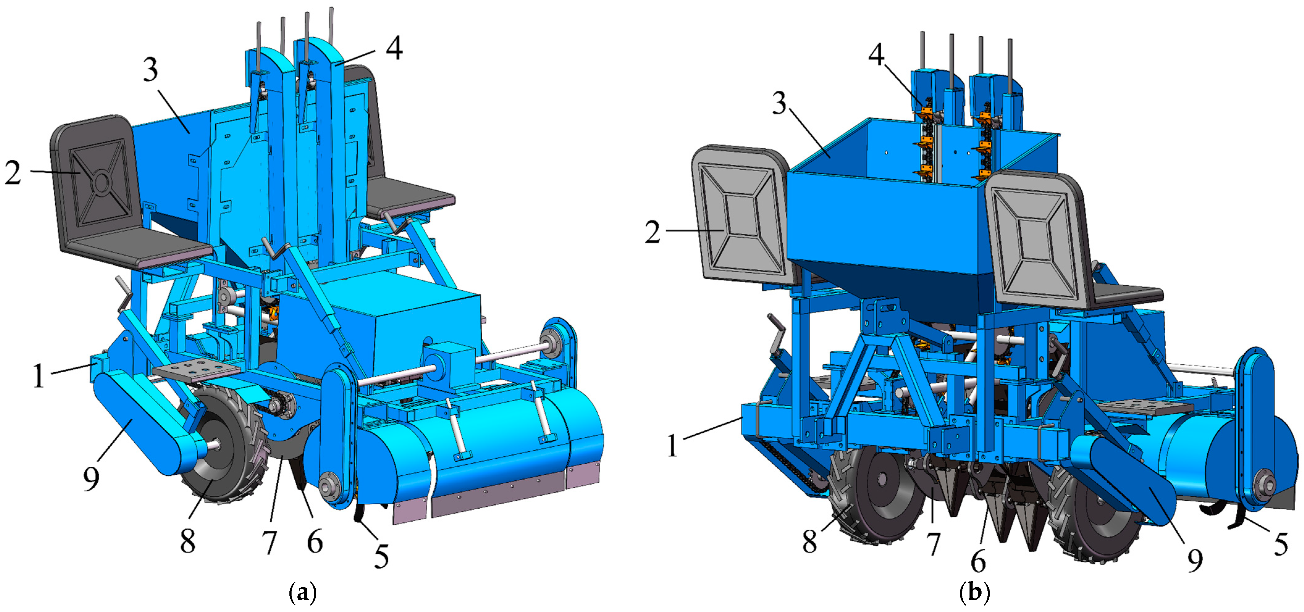
Figure 1 illustrates the overall configuration of the potato seeder, and Table 1 shows its main parameters. It comprises a spoon-feed metering unit, an eccentric coupling mechanism, a furrow-opening and seed-planting device, a soil-covering device, a ground wheel, a transmission system, a frame, two operator seats, and a seed hopper. This machine can efficiently perform seed selection, planting, and soil covering in a single pass.

Figure 1.
CAD models of the potato seeder: (a) left rear side and (b) left front side, with (1) rack, (2) seats, (3) seed box, (4) spoon-chain seeder, (5) soil-covering device, (6) hole-drilling and seeding device, (7) eccentric coupling mechanism, (8) ground wheel, (9) transmission system.

Table 1.
Main parameters of the potato-planting machine.
2.2. Working Principle
The potato seeder is attached to the tractor’s rear suspension system using a three-point hitch. During operation, the tractor pulls the seeder. The seeder’s ground wheel is driven by the tractor’s movement. This rotation is transmitted through the gearbox at a specific gear ratio to the spoon-type seed metering device, the eccentric coupling mechanism, and the planting unit. Potato seeds are fed by gravity from the seed box one at a time into the planting device via the spoon-chain conveyor. The eccentric coupling mechanism ensures that the planting unit remains upright throughout the process. A pulley on the eccentric coupling mechanism, designed with a convex groove, controls the opening and closing of the furrow opener (duckbill) while maintaining the unit’s upright position. This sequence completes the potato seed planting process [11].
2.3. Technical Requirements
The potato seeder is designed for large-scale, double-row cultivation on ridges. As illustrated in Figure 2, studies have shown that for dryland potato cultivation with mulch film and ridges, the highest water use efficiency and tuber yield are achieved with a planting density of 51,187–51,302 plants per hectare and a plant spacing of 320 mm. For optimal performance, a black mulch film with a width of 1200 mm and a thickness of 0.01 mm is recommended to cover the ridge.
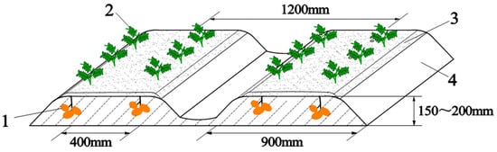
Figure 2.
Ridge shape of potato single-row and double-row cultivation mode with (1) seed potatoes, (2) potato seedlings, (3) mulch film, and (4) soil.
3. The Design of the Seeder’s Main Working Components
3.1. Seeding System
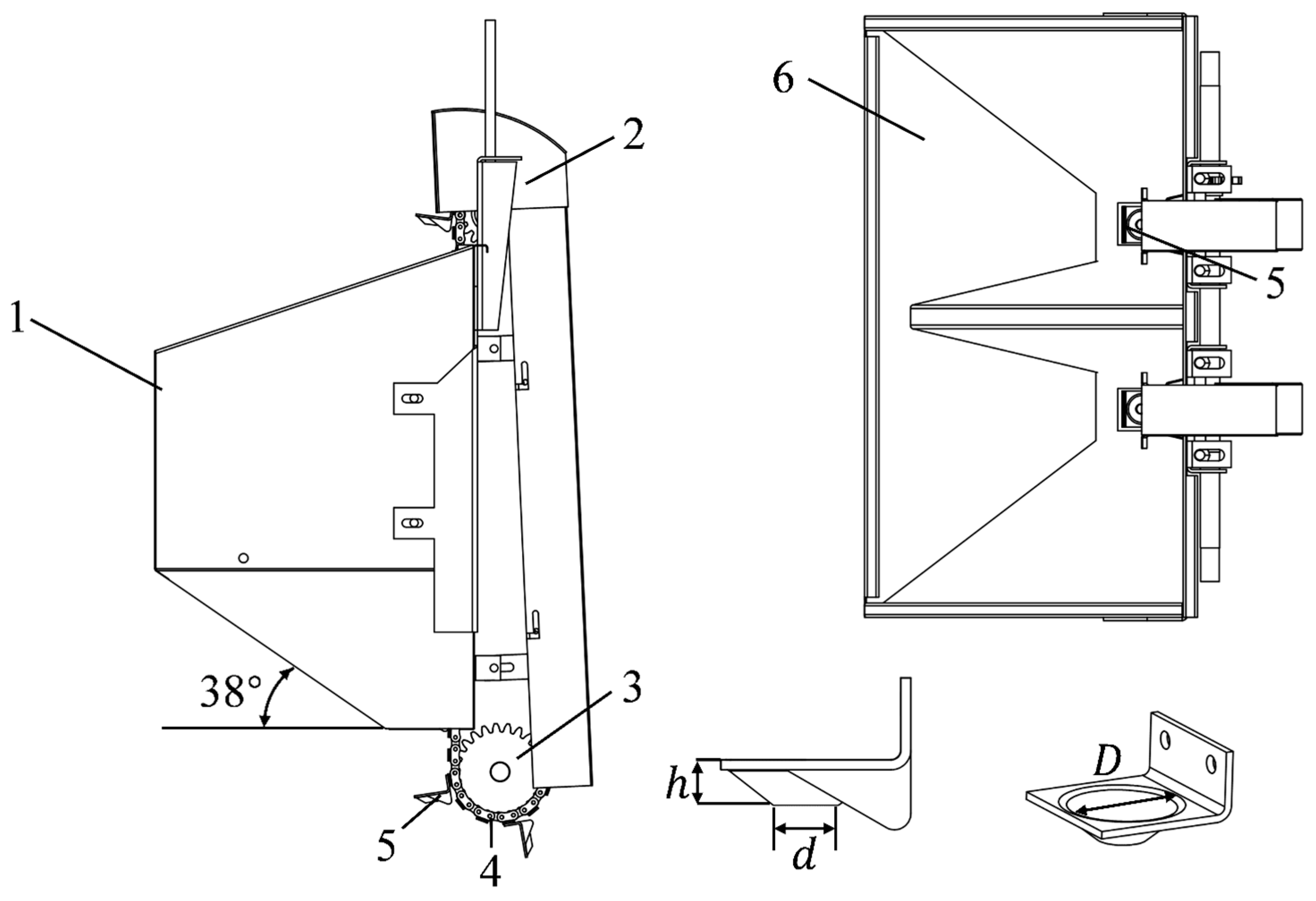
As illustrated in Figure 3, the seeder utilizes a spoon-chain seeding system. This system’s performance has been steadily improving in recent years, as evidenced by both research and practical application [12,13]. The key components of this system include a seed box, a seeding chain, the spoon-chain seeder itself, a seed guard plate, and an active sprocket.

Figure 3.
Schematic of spoon-chain seeding system showing (1) outside of seed box, (2) seed guard plate, (3) drive sprocket, (4) roller chain, (5) spoon-chain seeder, (6) inside of seed box.
To ensure sufficient sunlight, good ventilation, and maximized yield during potato seedling growth, a cross-planting method is employed between sowing rows [14]. Additionally, to enhance the seed-filling performance of the spoon-chain seeder, the two sowing rows are designed in a staggered configuration. This setup allows pre-cut seed potatoes to be poured into the seed box during operation. The seed spoon then elevates the potatoes sequentially. When the spoon reaches its highest point, the potatoes fall onto the opposite side. As the spoon reaches its lowest point, gravity directs the seeds into the planting device located at the bottom hole, completing the seed placement process [15].
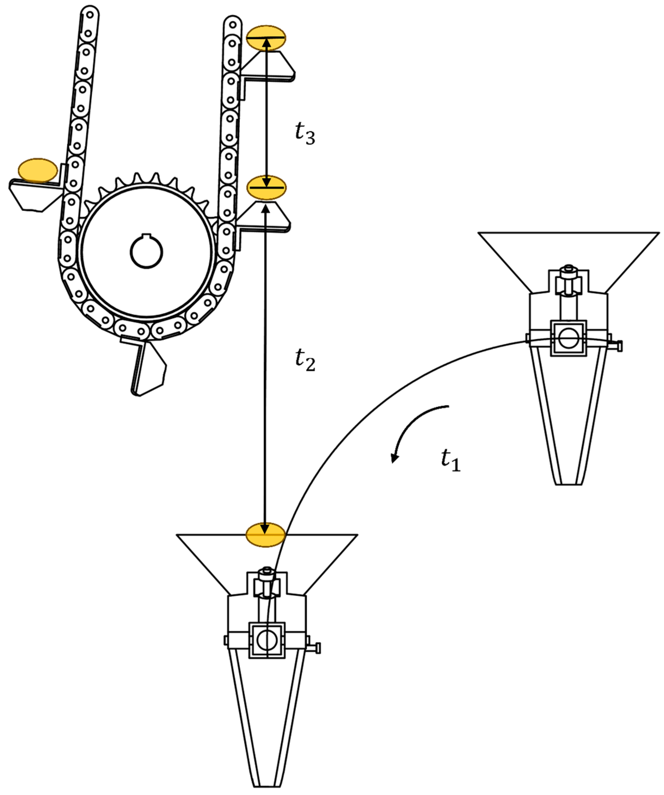
Figure 4 shows how the potato seeds on each sowing spoon fall sequentially into the hole-drilling and sowing device below [16]. The time t1 in seconds it takes the punching device to rotate a quarter of a turn is
where n2 is the rotational speed of the hole-drilling and seeding device in rad/s, t2 is the time it takes for the seed potato to detach from the seed spoon and fall onto the top of the hole-punching device, and t3 is the time it takes to walk through one adjacent spoon (both times are in seconds). The time t2 in Equation (1) is calculated with
where d is the radius of rotation of the hole-drilling and sowing device (taken as 204 mm), and g (equal to 9.81 m/s2) is the acceleration due to gravity.
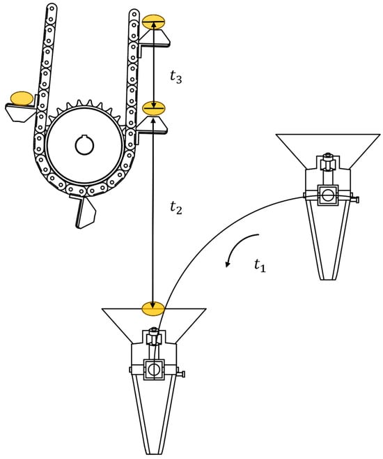
Figure 4.
Clockwise inoculation diagram of seeding device.
The rotational speed of the hole-drilling and seeding device can be calculated based on the ground wheel speed n1 and the transmission ratio i1 between the ground wheel and the hole-drilling and seeding device:
where i is equal to 1.25.
The forward speed of the implement is calculated with:
where is the ground wheel diameter. For = 510 mm, the forward speed is approximately equal to 0.5 m/s.
An important parameter setting for the operation of the machine is the distance S between adjacent seeding spoons, which is calculated with:
where i3 is the transmission ratio from the ground wheel to the seeding device and is equal to 25/28, and d3 is the pitch circle diameter of the seeding sprocket and is equal to 168 mm. With the above values, the distance S between adjacent seeding spoons becomes equal to 113 mm.
According to relevant experiments, the resting angle of potato seeds is maintained between 30° and 32°. In order to improve the seed-filling performance of the spoon-chain seeder while avoiding the phenomenon of the “dormant self-locking of the seed potatoes in the seed box”, as defined in reference [17], the bottom inclination angle of the seed box is set to 38°. A study on the size of seed potato cutting blocks presented in [18] suggests that the size of seed potatoes be in the range of mm. The top diameter of the spoon-chain seeder is D = 50 mm, the bottom diameter is d = 20 mm, and the height of the spoon-chain seeder is h = 18 mm.
3.2. Eccentric Coupling Device
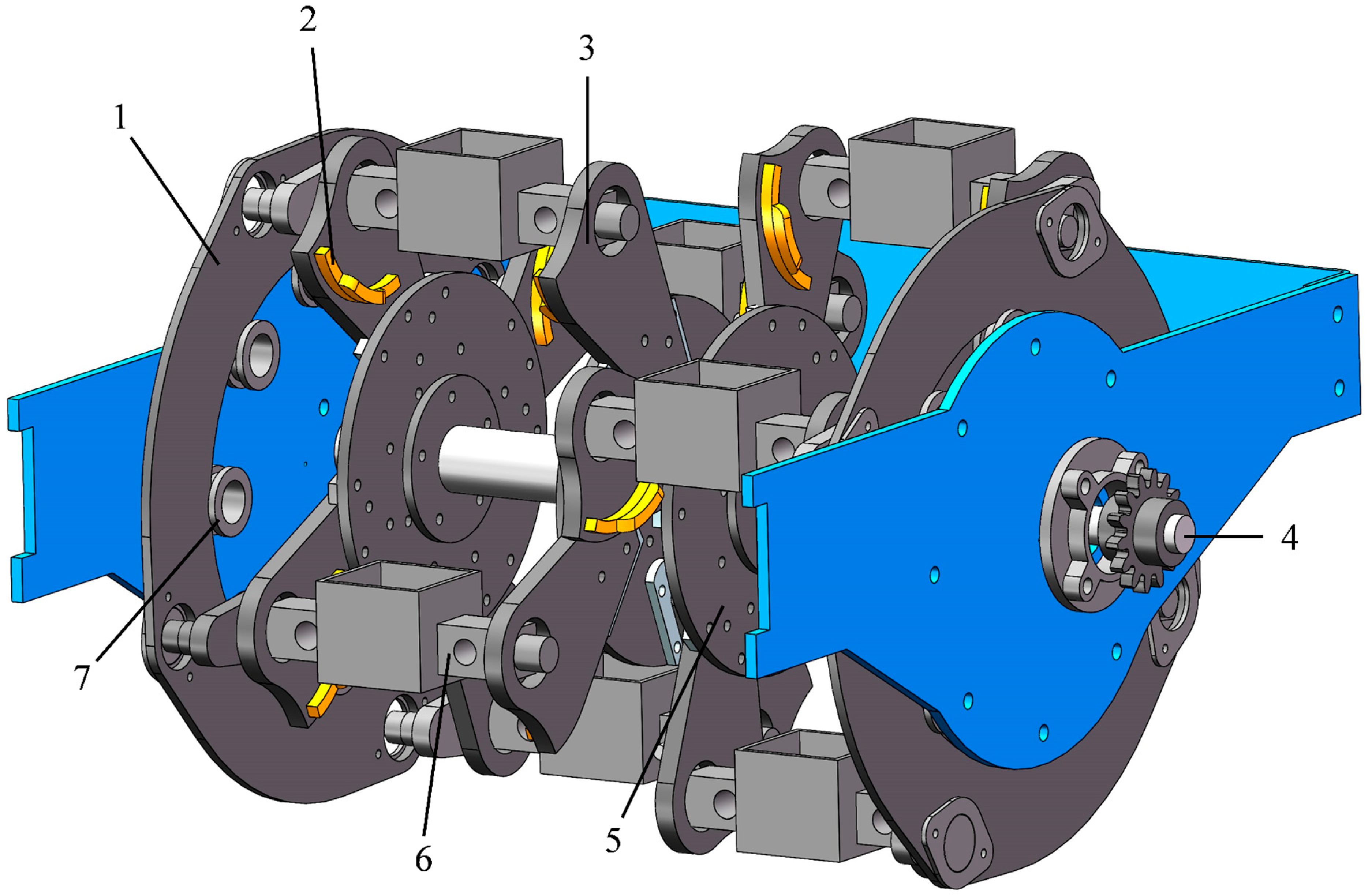
The eccentric coupling mechanism shown in Figure 5 consists of a pulley, a disc slide rail, a support plate for the hole-drilling and sowing device, a disc fixing plate, a connecting rod for the hole-drilling and sowing device, a sliding ring for the duck beak of the hole-drilling and sowing device, a driving shaft, etc. The disc fixing plate is installed on the drive shaft, and the pulley, together with the drive shaft, is installed on the frame. The disc slide rail is connected to the hole-punching seeder support plate through the hole-punching seeder connecting rod. The disc fixing plate is installed on the drive shaft, and the hole-punching seeder support plate is installed on the disc fixing plate. The sliding ring of the hole-punching seeder duck mouth is installed on the hole-punching seeder support plate to control the opening and closing of the hole-punching seeder duck mouth. The support plate of the hole-drilling seeder is rigidly connected to the disc fixing plate, and the connecting rod of the hole-drilling seeder is concentrically matched with the disc slide and the support plate of the hole-drilling seeder, allowing the hole-drilling seeder to remain upright and rotate in a circular direction [19].
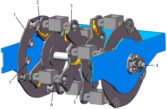
Figure 5.
Schematic of eccentric coupling mechanism, with (1) disc slide rail, (2) drilling and sowing duck-billed sliding ring, (3) hole-drilling seeder bracket plate, (4) drive shaft, (5) disc fixing plate, (6) connecting rod of hole-drilling seeder, and (7) pulley.
The power of the entire eccentric coupling mechanism is transmitted through the drive sprocket, which is installed on the drive shaft. The disc fixing plate rotates under the action of the hole-drilling and sowing drive shaft, and the disc sliding rail rotates in an eccentric circle through the action of the hole-drilling and sowing connecting rod [20].
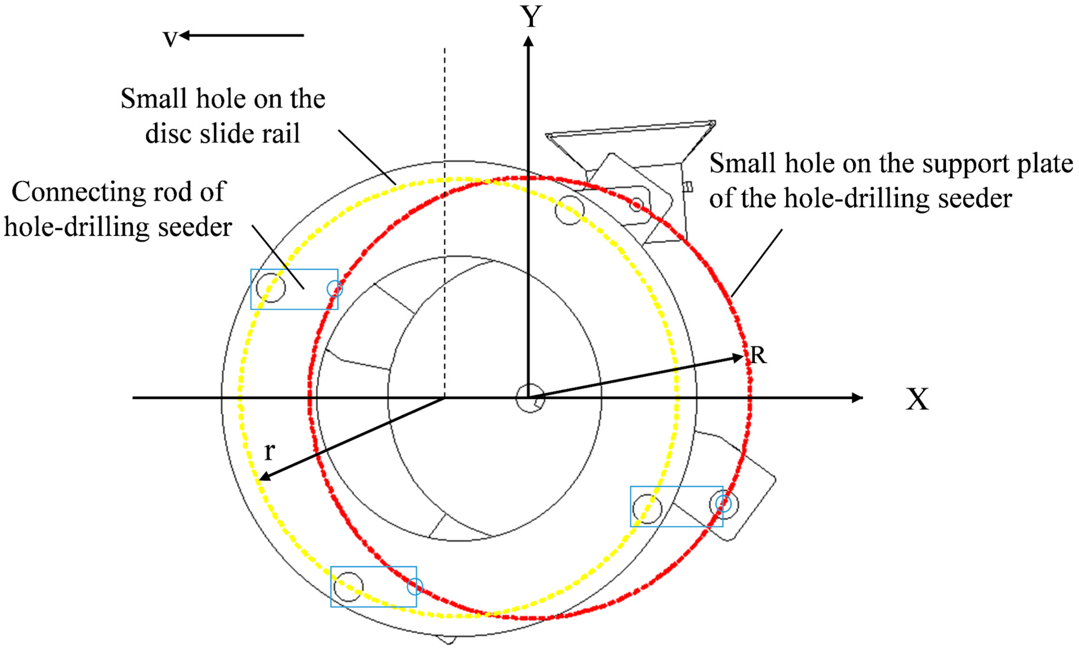
The motion trajectory of the eccentric coupling mechanism is actually a small circular motion, where the connecting rod of the hole-drilling seeder is concentrically aligned with the disc slide and the support plate. As shown in Figure 6, the eccentric disc slide rail hole and the support plate hole move uniformly in a circular path along the same X-axis but on different Y-axes, with their angular velocities ω being identical. For the motion analysis of the connecting rod in the hole-punching seeder, it is important to note that the amplitude of the concentric holes on the disc slide and the support plate are the same. Additionally, the machine moves forward at a uniform speed while performing the circular motion.

Figure 6.
Motion diagram of the eccentric coupling mechanism.
The agronomic requirement is that the plant spacing H is approximately equal to 320 mm, and it is related to the turning radius R of the eccentric coupling mechanism according to the following equation:
where Z = 4 is the number of hole-drilling and seeding devices, resulting in a turning radius R of the eccentric coupling mechanism equal to 204 mm.
The trajectory of the small hole on the disc fixing plate is described by
where the forward speed of the seeder, taken as 0.5 m/s, is
and where is the forward speed of the seeder, , taken as 0.5 according to the table; is the turning radius of the eccentric coupling mechanism, which is 204 ; is the ground wheel speed, , obtained from Equation (8) as 0.32 ; is the ground wheel diameter, , as shown in the table, and is taken as 510 ; and is the rotational speed of the eccentric coupling mechanism, equal to 0.51 , and calculated with equation:
The forward displacement X of the eccentric coupling mechanism is
where is the linear velocity of the eccentric coupling mechanism, m/s, and t is the time, s.
Using Equations (9) and (10), the plant spacing P, equal to 320 mm, was calculated with the following equation:
where Z = 4 is the number of duck bills for hole drilling and sowing.
3.2.1. Simulation and Motion Characteristic Analysis of Eccentric Coupling Mechanism
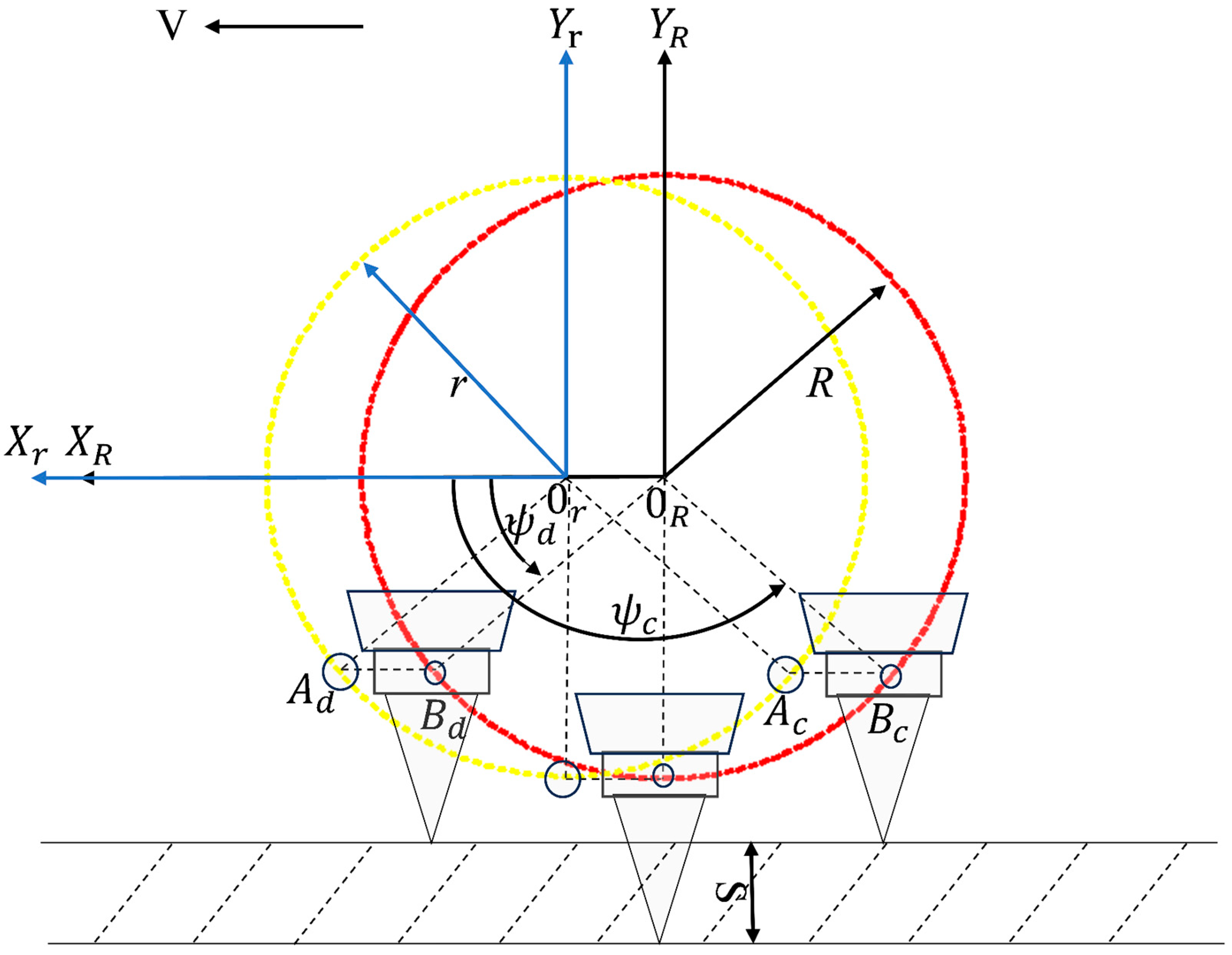
The eccentric coupling mechanism (Figure 7) provides a combined motion of four parallelograms moving horizontally and uniformly in a straight line while also moving in a circular motion [21]. The long side of the parallelogram is the horizontal length of the connecting rod of the hole-drilling seeder, and the long side is the half-diameter of the rotation when two small holes move in a circular motion, which is 204 mm.
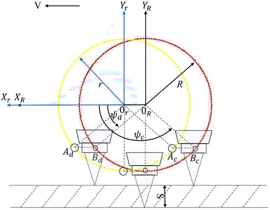
Figure 7.
A schematic diagram of the rotation principle of the eccentric coupling mechanism.
A is a small hole that fits concentrically with the disc slide rail, B is a small hole on the support plate of the hole-punching seeder, and AB is the length of the small hole in the connecting rod of the hole-punching seeder. When small holes A and B move in a circular motion, AB always remains horizontal; that is, the connecting rod of the hole-punching seeder always remains horizontal. The parallelogram in keeps the r side horizontal, and AB performs a horizontal circular motion.
3.2.2. Analysis of the Soil Entry by the Eccentric Coupling
The planting device installed on the connecting rod of the hole-drilling seeder can maintain a fixed angle and position below the hole-drilling seeder no matter how the eccentric coupling mechanism rotates, and the sowing tip is always vertical to the ground. It is ensured that each sowing tip can be vertically inserted and unearthed [22], as shown in Figure 8.
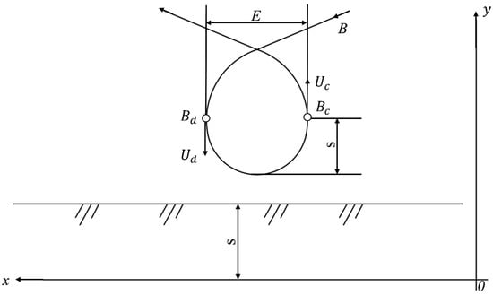
Figure 8.
The trajectory of the hole-forming device of the vertically directed soil hole seeder.
The parameter equation for the period from the insertion of the seeding tip into the soil to a certain sowing depth and from a certain sowing depth S to leaving the mulch film is
where is the distance between the origin of the xoy reference frame and the first hole; is the number of holes taken as 4; is the distance between holes (i.e., the plant spacing) and equal to 320 mm; is the angular coefficient; and is time.
The drilling and sowing tip is vertical to the ground when entering the soil, while the drilling and sowing machine support plate and the connecting rod of the drilling and sowing machine always remain horizontal. Therefore, the motion trajectory of the hinge point B is the motion trajectory of the drilling and sowing machine shown in Figure 8.
The hinge point B undergoes a cycloidal motion, and the motion trajectory of point B can only form a closed-loop curve for the cycloidal curve when the slip rate of the mulch film is constant. The width E of the closed-loop curve is determined by the ratio of the velocity v along the x-direction of the vertical soil planting machine and the tangential velocity V of point B’s circular motion around point , that is,
When the burrowing tool is vertically inserted and pulled out, the insertion stroke occurs when point B moves to point d, and the excavation stroke occurs when point d moves to point c. The absolute velocity d of the maximum arc point on the closed-loop curve is vertically downward. At point , the absolute velocity is upward. The height of half of the closed-loop curve should be the sowing depth S = 140 mm, and the maximum width E on the closed-loop curve is the maximum movement of point B in the x-direction from time d to time c during the hole-forming process.
Then, the velocity v at point B is
where is the forward speed of the implement, which is 0.5 ; is the ground wheel speed; is the eccentric coupling mechanism speed, ; is the transmission ratio from the ground wheel to the eccentric coupling mechanism and is taken as 1.25; and is the distance between the hinge point of the hole-forming device and the hole-drilling and sowing axis and is taken as 204 mm.
The equation for the trajectories of the cycloidal motion of the hinge point B at this time is
3.2.3. Hole Size Analysis
The trajectory of the hole seeding device is shown in Figure 9, which is compounded by the advance of the machine tool and the movement of the eccentric coupling hole seeding device, with the Z point as the reference point, and the equation of motion is
where is the forward speed of the implement, which is 0.5 ; is the eccentric coupling mechanism’s rotation angular velocity moving positive counterclockwise, which is 0.51 ; are the coordinates of point Z relative to the origin; is the radius of rotation of eccentric coupling and is taken as 204 mm; and is the time.
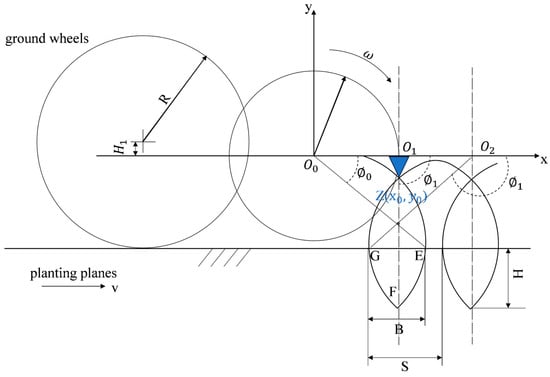
Figure 9.
The trajectory of the hole seeding device.
The depth of the hole directly determines the depth of planting. It can be seen in Figure 9 that when the size of the hole seeding device is determined, the key factor affecting the hole depth is the height difference between the central axis of the ground wheel and the central axis of the eccentric coupling device, so we can adjust the depth of the hole by adjusting the height of the ground wheel.
If the hole width is too large, the hole in the plastic film will be too large, which will affect the ability of the plastic film to retain moisture and store water. In Figure 9, the E end of the hole seeding device touches the ground, the F point reaches the deepest point, and the G end leaves the soil.
When the hole seeding device is point E, y = R, the polar angle is
The horizontal coordinates of points E and G are
Subtracting the two abscissas, we obtain the size of the hole:
from which we further obtain
In combination with Equation (24), we finally obtain:
For the numerical values considered, the hole size B = 110 mm.
3.3. Hole-Drilling and Seeding Device
The structure of the hole-drilling and sowing device is illustrated in Figure 10. It comprises several components: a sliding ring for the duck beak of the hole-drilling and sowing device, connecting rods for the device, a rotating shaft to support the hole-drilling and sowing needle, a protective plate, bearings, rotating rods for the needles, a return spring, and the hole-drilling and sowing needle itself.
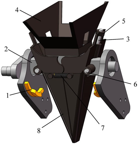
Figure 10.
Hole-drilling and seeding device, with (1) hole-drilling and sowing duck-billed sliding ring, (2) connecting rod, (3) hole-drilling and seeding pointed nozzle bearing rotating shaft, (4) hole-drilling seeder protective plate, (5) bearing, (6) hole-drilling and sowing pointed nozzle rotating rod, (7) return spring, (8) pointed nozzle for drilling and sowing.
The connecting rod and protective plate of the hole-drilling seeder are fixed in place. Two hole-drilling seeder tips are hinged on both sides of the protective plate along the rotation axis. These tips are connected by a return spring, with each tip equipped with a bearing. The rotation of the hole-drilling seeder mechanism is controlled by an eccentric coupling mechanism.
During rotation, the bearing contacts the sliding ring of the punching and sowing duckbill, causing the sowing tip to open. Once punching and sowing are complete, the return spring closes the tip, completing the process.
The power of the hole-drilling and sowing device is provided by the connecting rod of the device connected to the eccentric coupling mechanism.
In Figure 7, it can be seen that the connecting rod of the hole-drilling seeder is always parallel to the ground, so the two hole-drilling seeder duckbills installed on the hole-drilling seeder guard plate are also always perpendicular to the ground.
3.3.1. Constraint Analysis of Hole-Drilling and Seeding Device
The motion trajectory of the hole-drilling and seeding device is shown in Figure 11. The absolute motion of the hole-drilling and seeding device is composed of the eccentric coupling mechanism and the forward motion of the implement. The motion equation of the device is based on the reference point of the motion trajectory at point D.
where is the length below the axis of the duckbill connector for hole drilling and sowing in mm.

Figure 11.
A schematic diagram of the trajectory of the planting device.
The diameter of the designed hole-drilling and seeding disc drive spindle is r. In order to prevent collisions between point A and point B of the hole-drilling and seeding device during the seeding process, it is required that [23]. At the same time, in order to prevent collision between the bottom point A of the hole-drilling and sowing device and the top point C of the hole-drilling and sowing disc drive spindle during the throwing process, that is, when the bottom of the upper planting device and the left end of the lower hole-drilling and sowing device are on the same Y-axis, points A and C cannot collide.
When equals , , we obtain:
The eccentric coupling hole-drilling and sowing device serves as the central component of the potato hole sowing machine, illustrated in Figure 12. Regulating the spacing between plants and the depth of potato sowing involves manipulating the rotation of the drive shaft, the forward speed of the unit, and the opening motion of the duckbill for hole drilling and sowing. Reference [24] highlights the challenge of controlling the plant and hole spacing by adjusting the external dimensions of the drilling and sowing device. This paper presents a method based on RecurDyn V9R5 simulation analysis that alters the transmission ratio between the ground wheel and the drilling device to adjust the spacing between potato plants. This approach aims to achieve plant spacing that aligns with the requirements of potato agronomy.

Figure 12.
Eccentric coupling hole-drilling and seeding mechanism, with (1) on-demand pointed mouth, (2) connecting rod, (3) hole-drilling seeder protection plate, (4) disc slide rail, (5) driving sprocket of hole-drilling and seeding device.
3.3.2. Design of the Opening and Closing Mechanism of the Seeding Valve
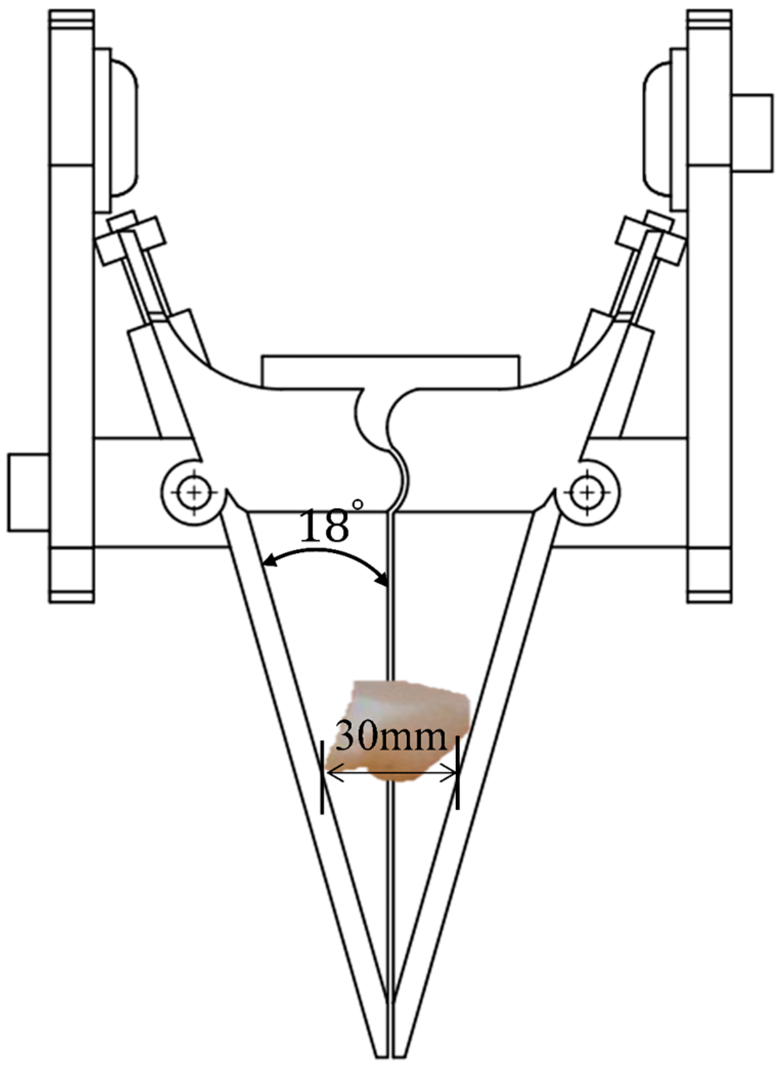
The duckbill for hole drilling and sowing is controlled by the pulleys mounted on both sides of the duckbill and the slide rails installed on the support plate of the hole-drilling and sowing device. Opening and closing occur when the pulleys come into contact with the slide rails. In order to meet the planting requirements, the opening time of the duckbill for hole drilling and sowing should be greater than the falling time of the seed potato in the duckbill, as shown in Figure 13 [25].

Figure 13.
Schematic diagram of planting potatoes in burrowing and sowing duckbills.
The block diameter of seed potatoes is generally between 25 and 30 mm. To ensure that the opening time of the duckbill during hole drilling is greater than the falling time of the seed potatoes, we selected a 30 mm sized cut potato block as a reference for analysis. Potato seeds undergo free-fall movements in the duck beak, and therefore:
where is the height of the free fall of the seed potato in the duck beak, taken as 46.17 mm; = 9.8 is the acceleration due to gravity; and is the free-fall time, calculated as 0.097 s.
To ensure that the potatoes eds can fall into the seed hole during the hole-drilling and sowing process, the opening time of the duckbill for hole drilling and sowing must be longer than . However, the contact time between the bearing and the duckbill sliding ring for drilling and sowing should be longer than.
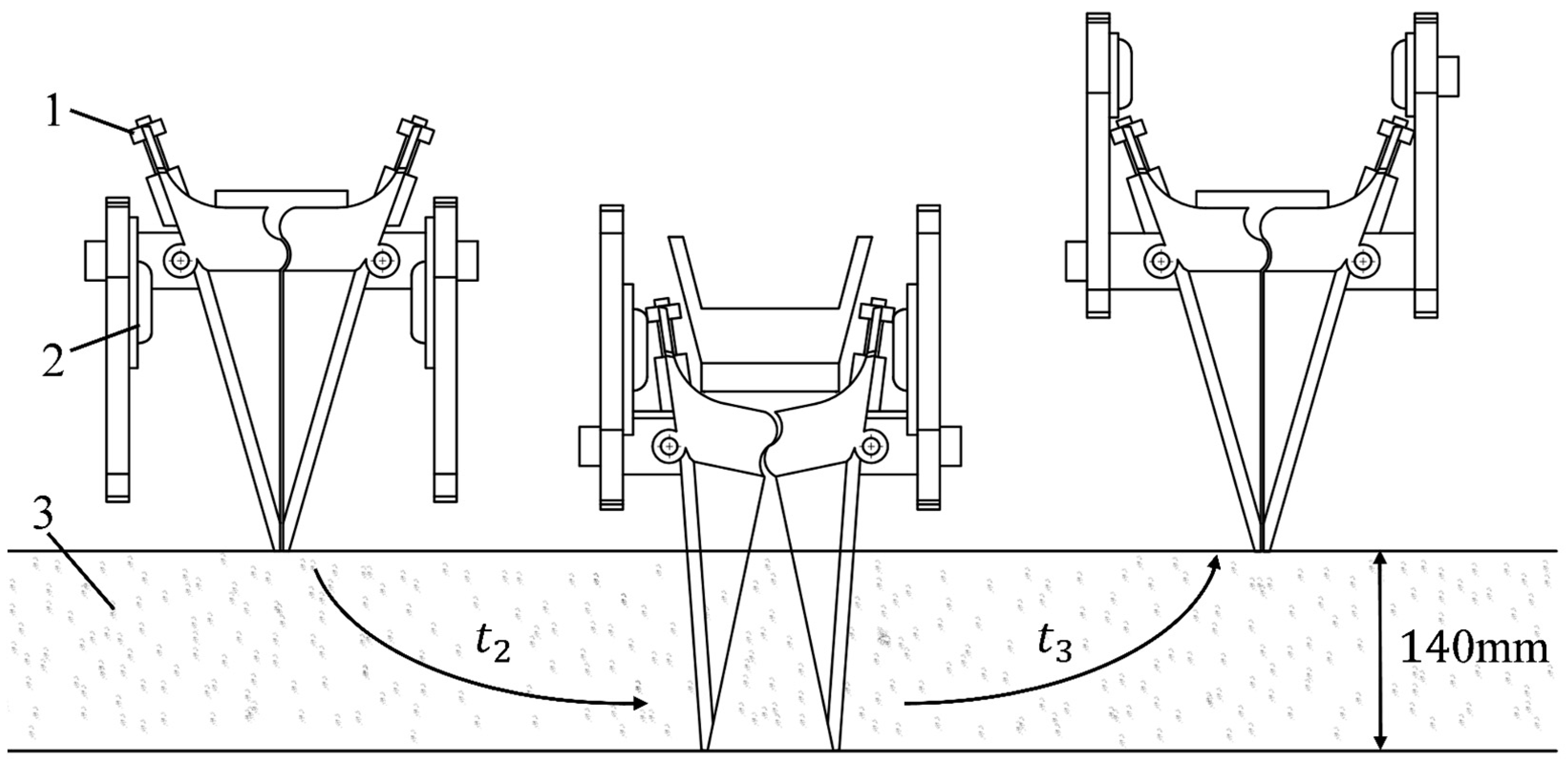
As the duckbill goes through the process of digging and sowing in the soil, if it is opened before reaching the lowest point, the soil at the lower end will fill the duckbill, making it impossible for the seed potato to reach the required planting depth for agronomy. Therefore, in order to achieve the theoretical planting depth for the seed potato, when the duckbill reaches the lowest point of the theoretical planting depth, the pulley contacts the sliding ring of the duckbill to make the duckbill open, ensuring the seed potato falls and completes the seeding, as shown in Figure 14.
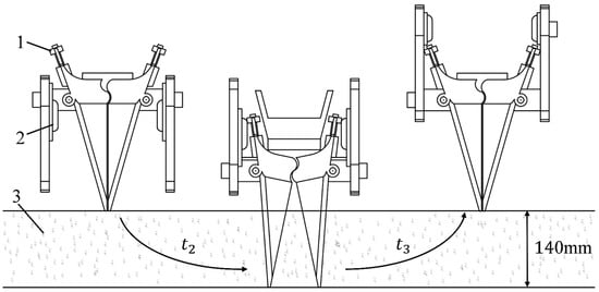
Figure 14.
Schematic diagram of the opening and closing mechanism of the seeding valve. (1) Bearing, (2) hole-drilling and sowing duck-billed sliding ring, (3) soil.
Therefore,
where is the forward speed of the implement and taken as 0.5 ; is the ground wheel speed, ; is the ground wheel diameter and taken as 510 mm; is the speed of the eccentric coupling mechanism, ; i is the transmission ratio from the ground wheel to the punching device and taken as 1.25; T is the time required for one revolution of the eccentric coupling mechanism; t is the total time of contact between the duckbill and soil during hole drilling and sowing; d is the turning radius of the eccentric coupling mechanism and taken as 204 mm; s is the sowing depth of potato seeds and taken as 140 mm; t2 is the duck beak closure time for hole drilling and sowing; and t3 is the opening time of duckbill for hole drilling and sowing.
After calculation, it was found that the opening time of the duckbill for hole drilling and sowing was 0.44 s, which was much longer than the falling time of the duckbill for seed potatoes during hole drilling and sowing, meeting the requirements for seed application.
3.4. Simulation Analysis of Hole Formation Process
A three-dimensional model of the eccentric coupling planting device was established and imported into RecurDyn V9R5 to add structural and motion constraints. The forward speed of the machine was set to v = 0.5 , and the driving sprocket of the planting device was set to 20 teeth.
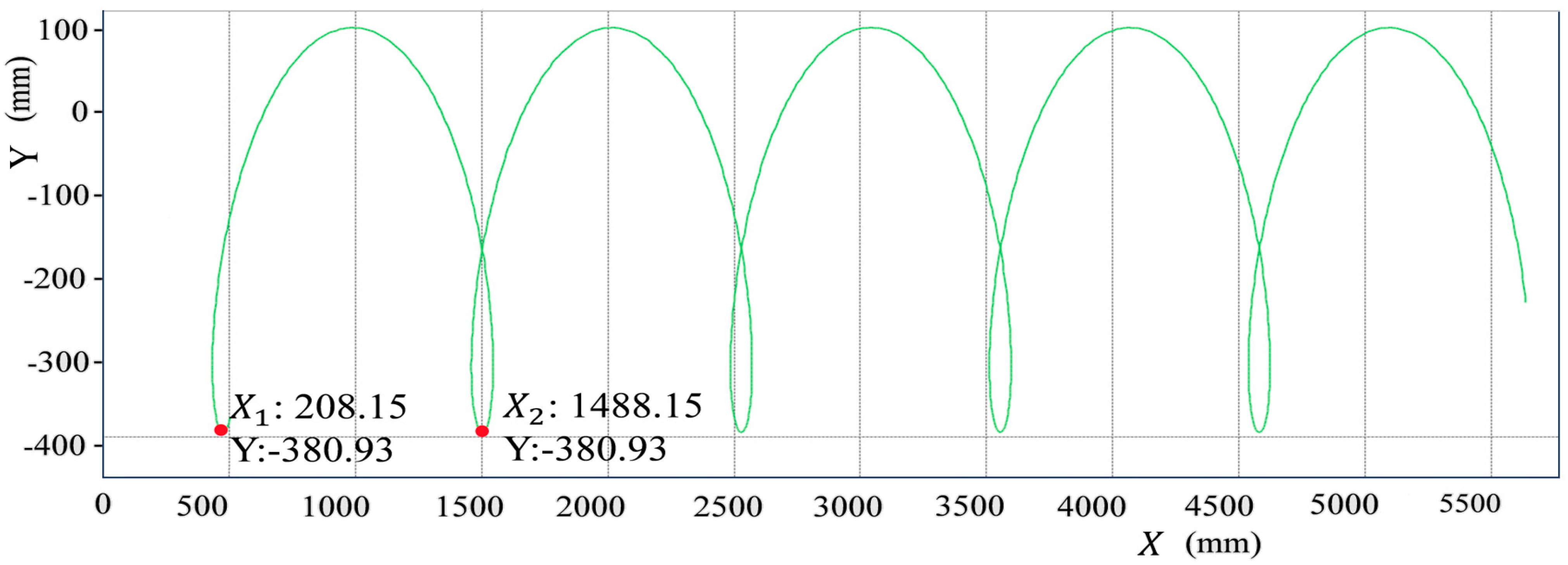
After simulation, the trajectory of the bottom of the drilling and seeding tip relative to the ground was generated and is shown in Figure 15 and Figure 16.
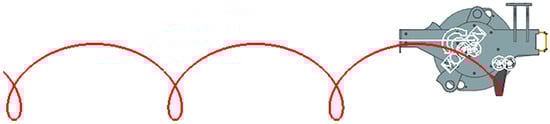
Figure 15.
Simulation of the trajectory of the drilling and seeding tip for a 20-tooth sprocket.
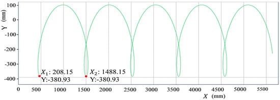
Figure 16.
Parameters of the trajectory of the drilling and seeding tip for a 20-tooth sprocket.
Detailed geometry of the trajectory of the drilling and seeding tip is shown in Figure 16. When the number of teeth on the drive shaft sprocket is 20, the plant spacing P is
where Z is the number of hole-drilling and seeding devices, equal to 4.
According to this formula, when the number of teeth on the drive sprocket of the hole-drilling and sowing device is 20, the plant spacing is 320 mm and satisfies agronomic requirements.
3.5. Device for Soil Covering of Membrane
After sowing, when a layer of soil with a thickness of 40 mm is applied to cover the local mulch film, the emergence rate of potato seedlings is the highest. The rotary tiller blade can achieve lateral soil throwing [26,27]. During operation, the power of the rotary tiller blade is transmitted from the tractor to the gearbox, which drives the rotary tiller soil-covering device to work. The rotary tiller blade acts on the ridge side, breaking and throwing soil on the ridge side to complete the soil-covering operation.
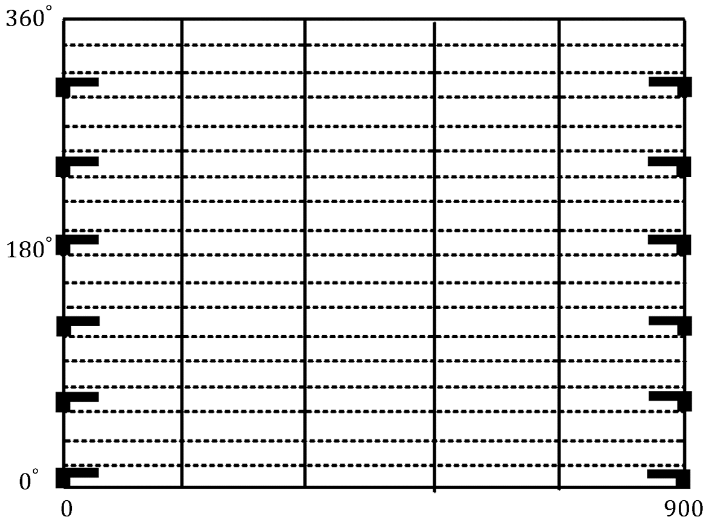
To ensure sufficient soil coverage on the mulch during the rotary tillage process, the rotary tiller blades on the cutter head are installed internally, and the arrangement and expansion of the rotary tiller blades are shown in the diagram in Figure 17.
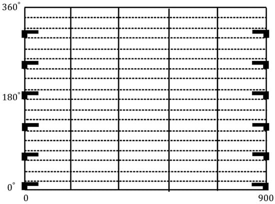
Figure 17.
Schematic diagram of the arrangement of rotary tillers.
3.5.1. Analysis of Soil Coverage by Rotary Tillers
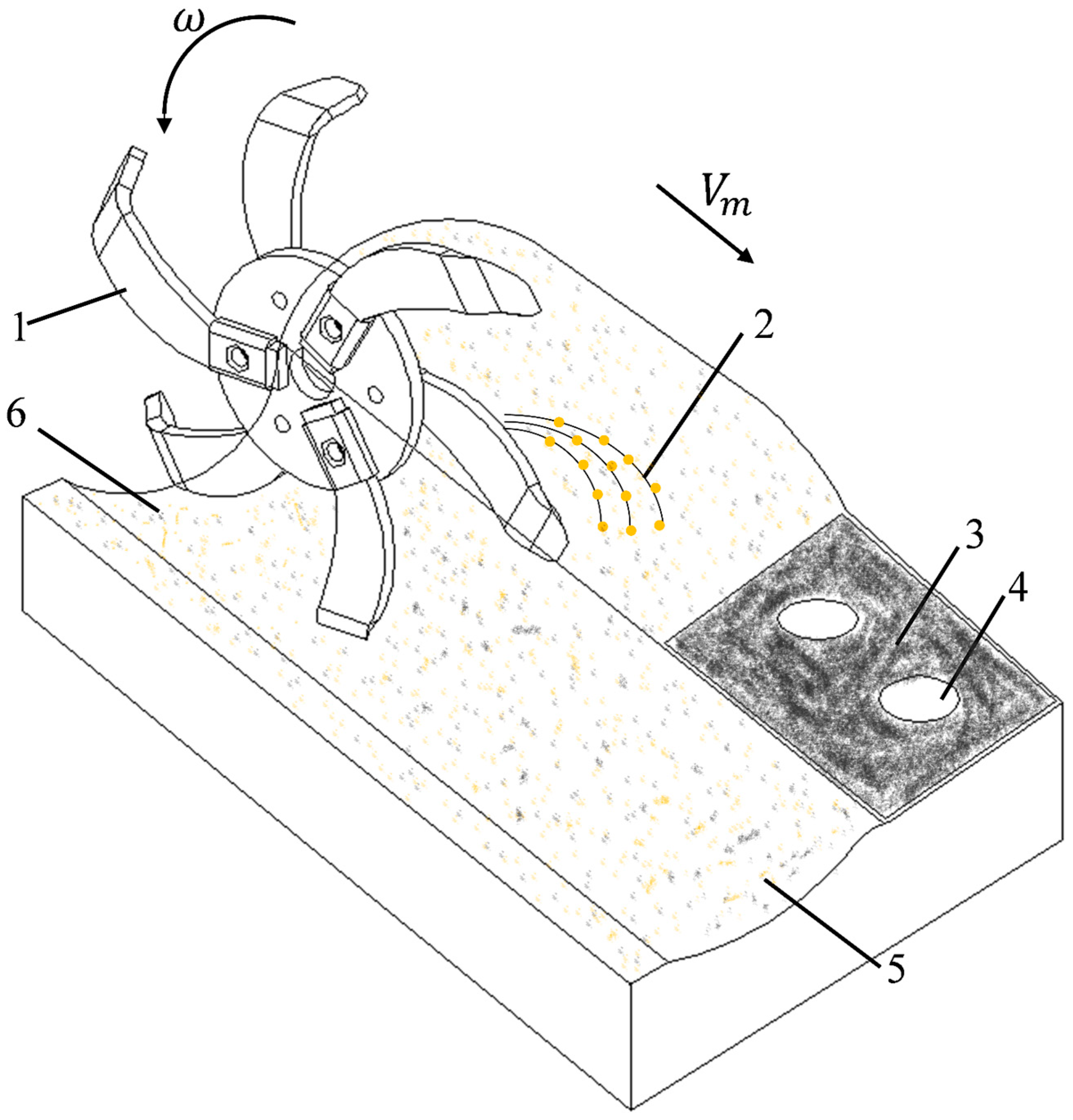
The direction pointed by the rotary tiller blade is the direction of soil throwing [28]. The process of soil throwing by the rotary tiller blade is shown in Figure 18. The forward speed of the machine is , and the angular velocity of the rotary tiller blade is . The rotary tiller rotates to lift the soil to locate and cover the holes, forming deeper ridges and ditches that remain after the rotary tiller operation. To ensure a thickness of 40 mm of soil covering the membrane, it is necessary to analyze the amount of soil covering the membrane surface and the soil cutting volume within a single rotation of a single rotary tiller blade [29].
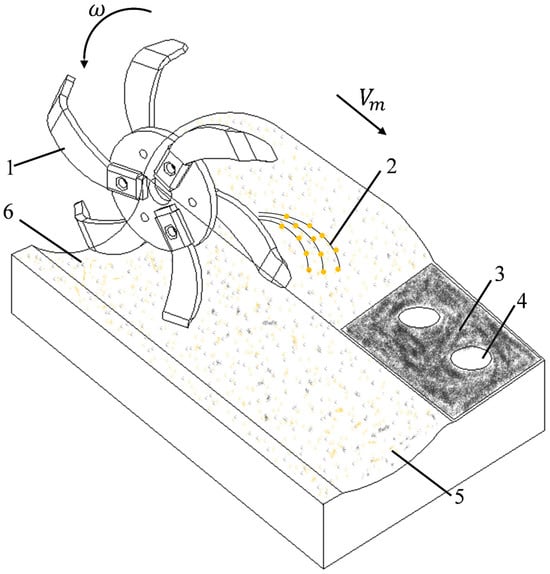
Figure 18.
Schematic diagram of rotary tillage and soil throwing, with (1) rotary tiller, (2) soil particles, (3) black mulch film, (4) hole, (5) potato-planting cover soil belt, (6) ridge and furrow.
3.5.2. Analysis of Cutting Area of Rotary Tiller Blades
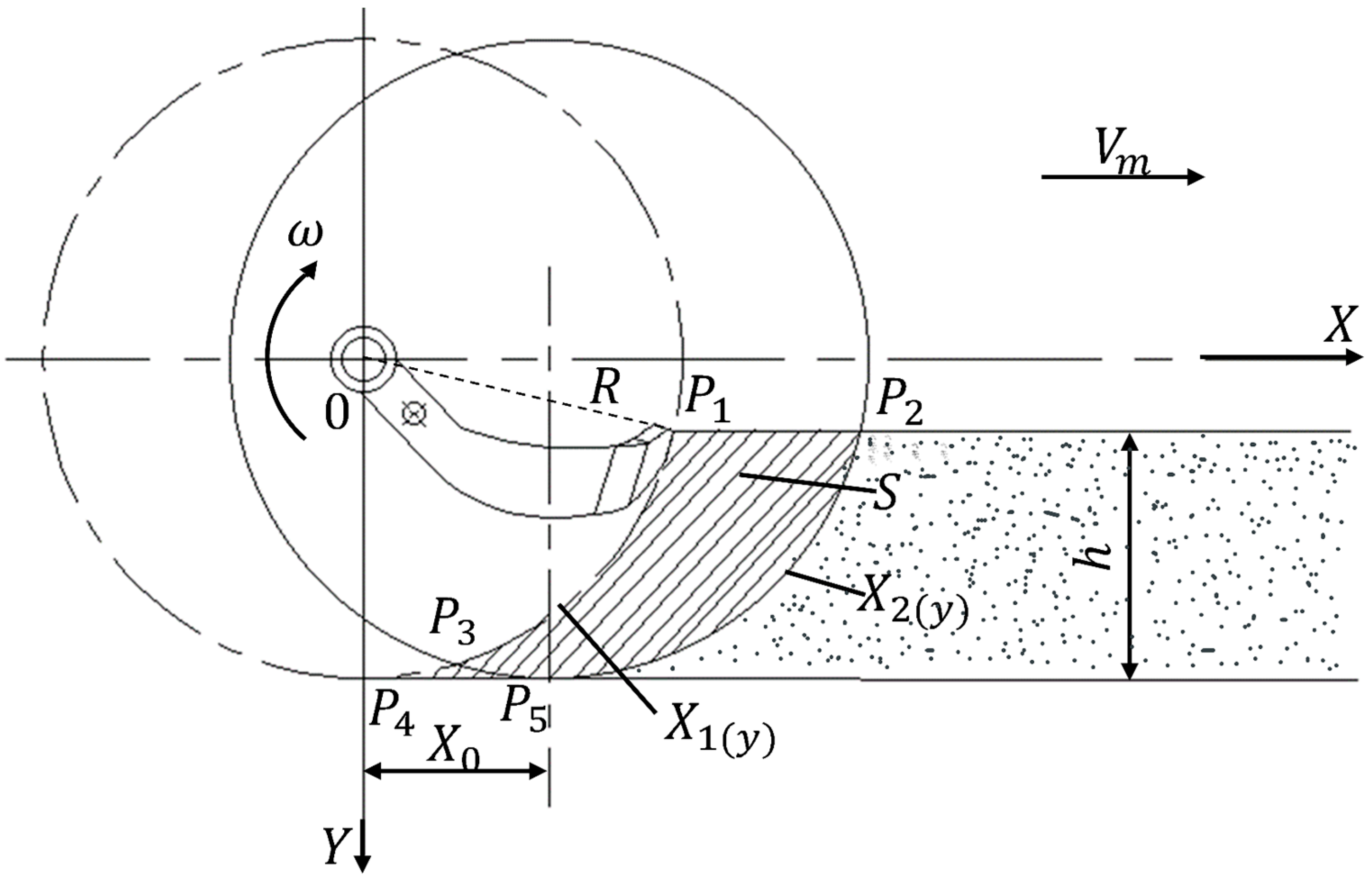
To analyze the motion process of the rotary tiller blade, a Cartesian coordinate system, as shown in Figure 19, is chosen, with point O as the origin, the forward direction of the tool as the x-axis, and the y-axis perpendicular to the foil surface. The cutting area S of the rotary tiller blade during a certain period is determined, the soil cutting thickness T of the rotary tiller blade at this time is calculated, and a parameter equation for the disturbance volume of the rotary tiller blade is established. The absolute motion trajectory of the rotary tiller blade is the combination of the forward motion of the implement and the uniform rotation motion of the rotary tiller blade, which is a cycloid [30].
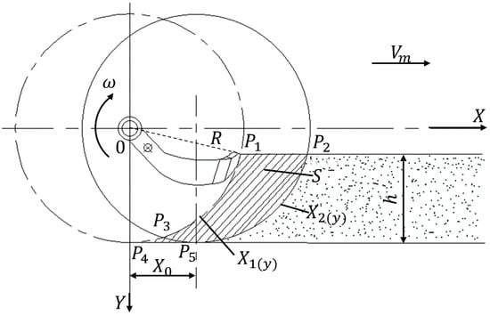
Figure 19.
Schematic diagram of the cutting area of the rotary tiller blade.
In Figure 19, the soil cutting area of a single rotary tiller blade in one full rotation is delimited by points , , , and . This shadow area can be calculated with
where is the equation of the trajectory of the first rotary tiller blade, and is the equation of the trajectory of the second rotary tiller blade within the same cycle. The parametric trajectory of the tip of the first blade is
There are a total of six rotary tiller blades, and the second blade lags behind the first one by an angle of π/3. Therefore, the equation of the trajectory of the tip of the second blade will be
The cutting pitch coordinate in Equation (34) is
where Z = 6 is the number of rotary tiller blades per side.
We can now calculate the available soil cutting area S as
where is the time in s; is the tillage depth in mm; is the radius of the rotary tiller blade in mm; and ω is the rotation angle speed of the rotary tiller blade in rad/s.
The cutting volume V of a single rotary tiller blade in one cycle is the product of the soil cutting area S and the soil cutting thickness T given by the equation:
The volume of soil per one side covered by one rotation on is
where is the cutting length of the rotary tiller blade in mm, and θ is the tangential blade bending angle.
According to Equations (35)–(38), it can be inferred that the cutting volume V of the rotary tiller blade is related to the parameters , , , , , , and For a given rotary tiller blade, the parameters R, L, and θ have fixed values. The amount of soil applied to cover the membrane surface is mainly affected by the depth of cultivation h and the rotational angular velocity ω. Other influencing factors are the number of rotors Z and the forward speed of the machinery V. When the forward speed V of the implement is constant, the rotational angular velocity and tillage depth are the main factors affecting the thickness of the soil cover [31].
3.6. Transmission System
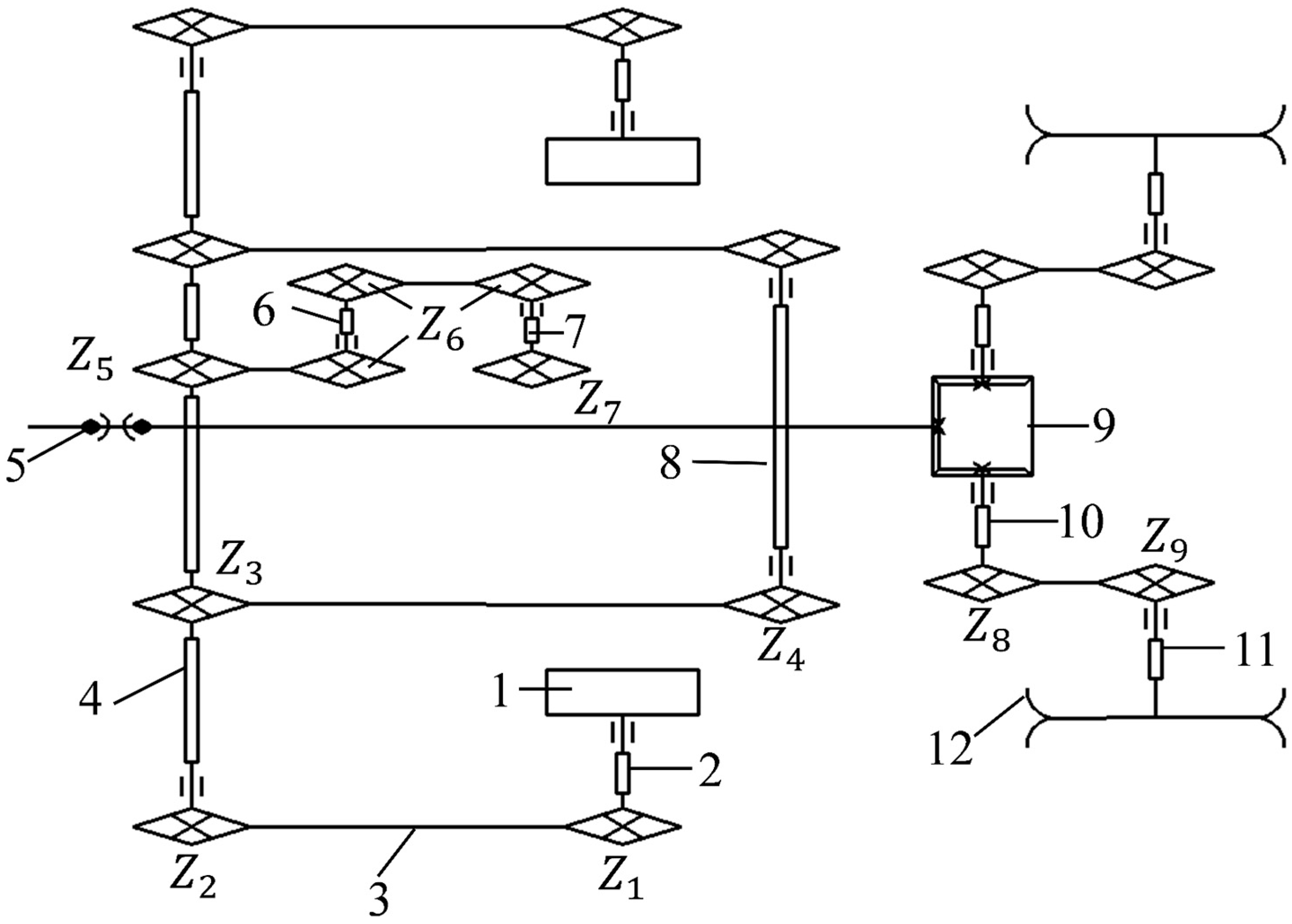
As shown in Figure 20, the hole seeder utilizes a rear three-point hitch system for its attachment to a four-wheel tractor. During operation, the ground wheel drives the main transmission shaft via a chain transmission system. This shaft then powers both the spoon-chain seeder and the eccentric coupling shaft of the hole seeder. The spoon-chain seeder driving shaft and the eccentric coupling device driving shaft work in conjunction to control the hole-drilling and seeding mechanism.
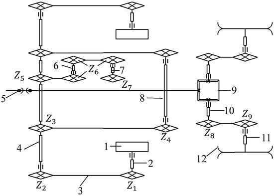
Figure 20.
Transmission diagram of potato seeder, with (1) ground wheel, (2) ground wheel shaft, (3) chain transmission, (4) main drive shaft, (5) coupling, (6) steering shaft, (7) spoon-chain seeder driving shaft, (8) eccentric coupling hole-drilling and seeding device active shaft, (9) differential, (10) differential driving shaft, (11) rotary tillage driving shaft, (12) rotary tillage.
A separate rotary tillage soil-covering device is powered directly by the tractor’s engine. The tractor’s power output is transferred through a coupling to the gearbox, which drives the rotary tillage knife shaft. This shaft rotates the cutting knives, which till the soil in the ridges and ditches and deposit it on the mulch film surface, completing the soil-covering process.
To meet the agronomic requirements for sowing, if the ground wheel rotates once, the active shaft of the eccentric coupling hole-drilling and sowing device rotates according to the equation
where is the number of teeth on the ground wheel shaft sprocket and taken as 25; is the number of teeth in the input sprocket of the main drive shaft and equal to 20; is the number of teeth in the output sprocket of the main transmission shaft and equal to 20; and is the number of teeth in the input sprocket of the drive shaft of the eccentric coupling hole-drilling and seeding device and equal to 20.
The number of hole-drilling and seeding devices P for each rotation of the ground wheel is
where d is the rotational diameter of the eccentric coupling hole-drilling and seeding device and equal to 408 mm, and Z is the number of duck bills for hole drilling and sowing and equal to 4.
Consequently, the distance X between two successive potato plants will be
where is the diameter of the ground wheel equal to 510 mm, and based on the above Equations (39)–(41), it can be inferred that X = 320 mm.
For every rotation of the ground wheel, the corresponding number of rotations of the driving shaft of the seeding device is
where is the number of teeth on the steering shaft sprocket and equal to 20, is the number of teeth on the steering shaft sprocket and equal to 20, and is the number of teeth on the driving shaft sprocket of the seeding device and equal to 28.
For each revolution of the ground wheel, the forward distance S of the seeding chain will be
where is the diameter of the pitch circle of the driving shaft sprocket of the seeding device and equal to 168 mm.
The spacing H between the spoons on the seeding chain is calculated with
and, using Equations (42)–(44), it was found to be H = 113 mm.
3.7. Simulation of the Plastic Film Breaking and Hole Formation by the Hole Seeding Device
3.7.1. Smoothed Particle Hydrodynamics Model
To assess potential film tearing during the normal operation of the designed hole seeding device, we employed a combination of RecurDyn and ANSYS 2019R1 /LS-DYNA (ANSYS, Inc., Canonsburg, PA, USA). Utilizing the MAT147 soil material model and Smoothed Particle Hydrodynamics (SPH) theory, a three-dimensional simulation of the film-breaking and cavity-forming processes of the potato hole seeding mechanism has been performed. The analysis confirmed that the designed potato hole seeding mechanism limits the film-tearing phenomena.
Since SPH cannot incorporate the non-reflective boundary conditions characteristic of geodynamic systems, a fluid–structure interaction method that combines SPH and FEM was employed to simulate the film penetration and hole formation by the hole seeding device. For this numerical simulation, we selected the MAT147 soil material model provided by LS-DYNA R11.0.0 software, which utilizes a modified Mohr–Coulomb yield criterion:
where P is the sowing pressure in N; φ is the internal friction angle; J2 is the second invariant of the stress bias tensor; K(θ) is tensor plane function angle; c is the sowing cohesion in N; and γ is the parameters that define the fit between the modified yield surface and the standard Mohr–Coulomb yield surface. Note that when γ is equal to 0, Equation (45) becomes the standard Mohr–Coulomb criterion [32].
Soil samples were collected from the potato-planting base of Sanniu Agricultural Machinery Manufacturing Co., Ltd., located in Weikou Town, Dingxi City, in northwest China’s loess gully area. The loess soil is a typical cohesive soil, characterized by high density and strong internal friction. To analyze its mechanical properties, a three-axis shear test was conducted on the samples. The samples were cylindrical, with a height of 11 cm and a diameter of 5 cm. The shear stress τ is the ordinate, the normal stress σ is the abscissa, (σ1 + σ3)/2 is the center of the circle at the time of failure, and (σ1 − σ3)/2 is the radius. The total stress circle of failure is drawn on the τ~σ coordinate system, and the envelope of the total stress circle of failure under different surrounding stresses is drawn. The cohesive force was 16.7 × 10³ Pa, and the internal friction angle was 21°. The moisture content of the soil sample was 12.8% and determined by the drying method. The density test showed that the soil particle density (bulk density) was 2100 kg/m3, and the soil particle relative density index was 2.1, which makes it a typical cohesive soil. A summary of the soil sample’s measured parameters is shown in Table 2. The remaining parameters correspond to *MAT_FHWA_SOIL and to Soil Material Model 147 in LS-DYNA.
Table 2.
Partial parameters of soil samples.
3.7.2. Simulation Model Establishment
Due to the symmetry of the burrowing seeding device shape, to improve the efficiency of simulation and calculation, a simplified model was created by simulating and calculating only half of the burrowing seeding device and the surrounding soil. A 3D parametric model was developed in Pro/E 5.0 and imported into the Ansys/LS-DYNA environment. The unit type used for both the burrowing seeding device and the external soil model was shell element type 181 of the Lagrange algorithm. Different material properties were assigned to each to allow for independent parameter adjustments within LS-DYNA971. As shown in Figure 21, in order to simplify the creation of Node and Segment groups, free meshing was used for the burrowing seeding device, while mapped meshing was used for the external soil model. After meshing, the model was exported as a K file for further preprocessing in LS-Prepost.
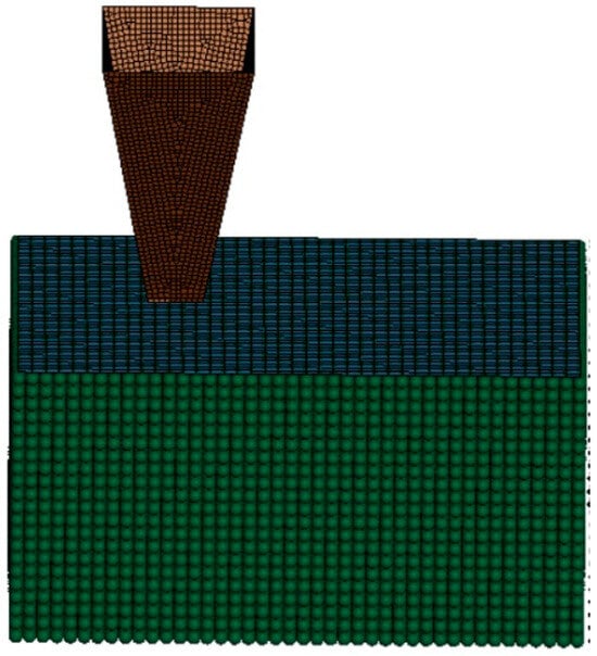
Figure 21.
The model diagram of the hole seeding device.
The burrowing seeding device was assigned 65 Mn steel as the material with a density of ρ = 7850 kg/m3, an elastic modulus of E = 0.21 × 10¹² Pa, and a Poisson’s ratio υ = 0.3 [32]. The internal soil model was created using the Smoothed Particle Hydrodynamics (SPH) meshless method in LS-Prepost. The material model selected was MAT147 (MAT_FHWA_SOIL). To balance accuracy with simulation time and avoid issues with initial penetration, the internal SPH soil model was set to a height of 200 mm, a width of 300 mm, and a length of 100 mm. The contact interaction between the burrowing seeding device and the soil was set to a fluid–structure interaction mode of AUTOMATIC_NODES_TO_SURFACE.
3.7.3. Soil-Cutting Simulation Results
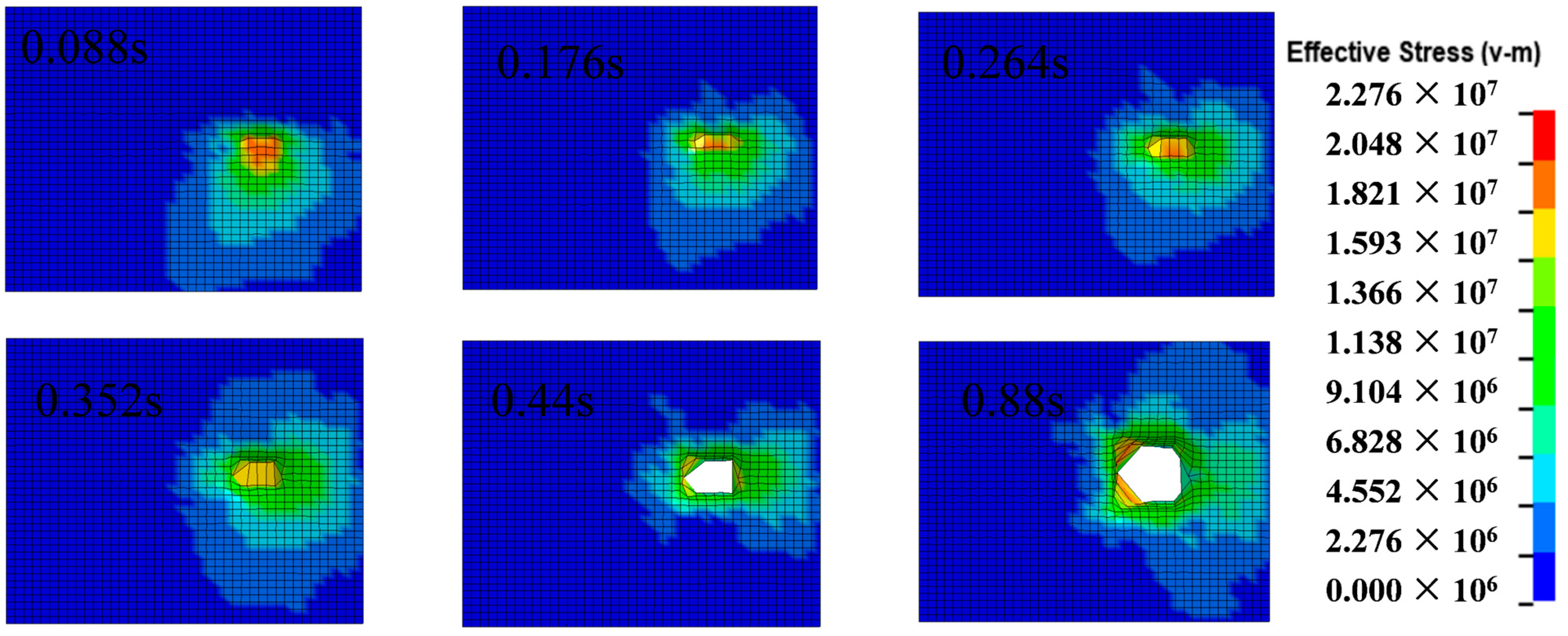
The vibration displacement curves in the X- and Y-directions of the hole-punching seeding device generated by Recurdyn were loaded with the LS-DYNA 971 keyword DEFINE_CURVE and replaced with a CSV suffix read. They were loaded with BOUNDARY_PRESCRIBED_MOTION_RIGID to apply vibration displacement curves in the X- and Y-directions, respectively. The LD-DYNA 971 program was used to simulate the process of breaking the film and opening the hole of the potato hole seeding mechanism, as shown in Figure 22. Figure 22 shows that the plastic film is not broken at 0~0.352 s. At 0.352 s, the deformation of the plastic film is in the maximum state. When the time reaches 0.44 s, the plastic film is broken under the combined action of the cavitation device and the soil; the cavitation device leaves the ground at 0.88 s, and the plastic film is not torn, so the design is reasonable.
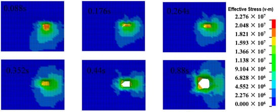
Figure 22.
A diagram of the process of rupturing and opening by the potato hole seeder.
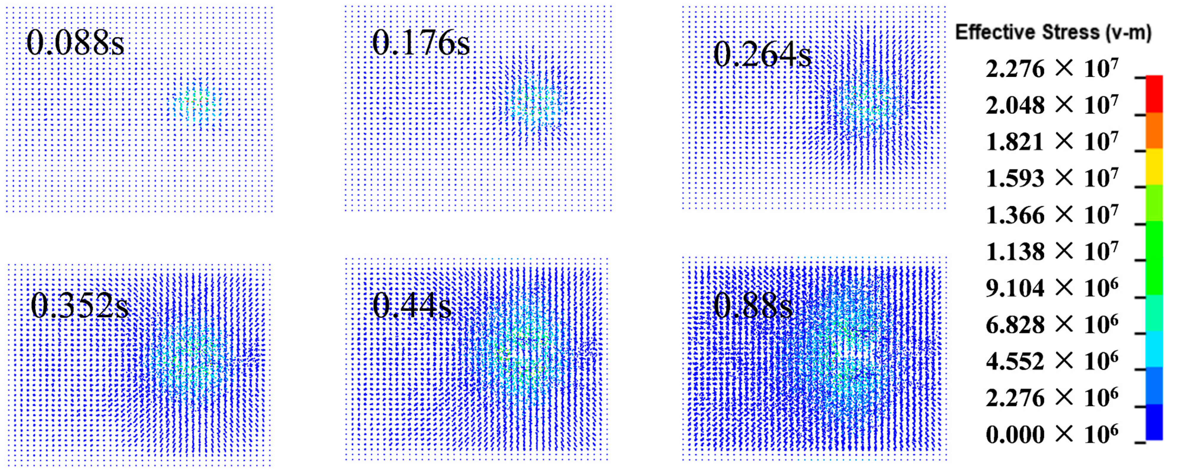
According to Figure 23, the stress distribution of the soil increases over time during the film breakage and hole formation process. The disturbance caused by the hole-forming device to the surrounding soil is minimal, which positively impacts the later-stage growth of potatoes. Simultaneously, it prevents the surrounding soil from protruding and failing to adhere closely to the plastic film and the ground, thus reducing the temperature of the potato growth environment. This, in turn, mitigates the warming and entropy retention effects of the plastic film.
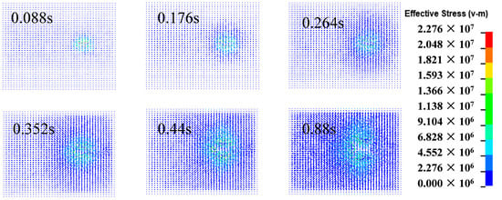
Figure 23.
Stress distribution of soil during film breakage and hole formation.
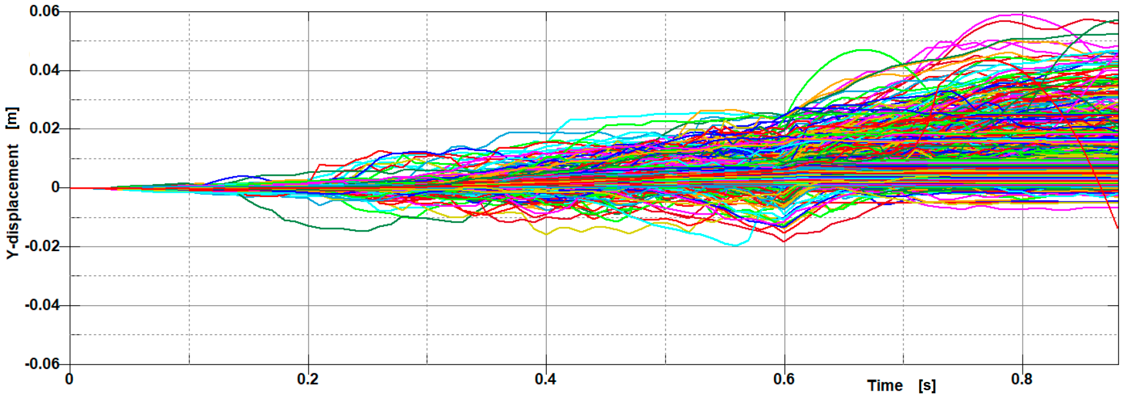
Figure 24 and Figure 25 show the displacement of soil particles in the y- and x-directions as a function of time extracted by the LS-DYNA post-processor. Note that y represents the forward direction of the unit, and x represents the vertical direction of the potato ridge section; y represents the direction of soil depth.
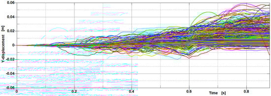
Figure 24.
The displacement of soil particles in the y-axis direction.
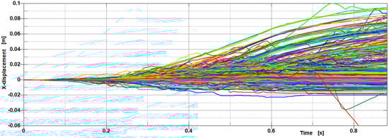
Figure 25.
The displacement of soil particles in the x-axis direction.
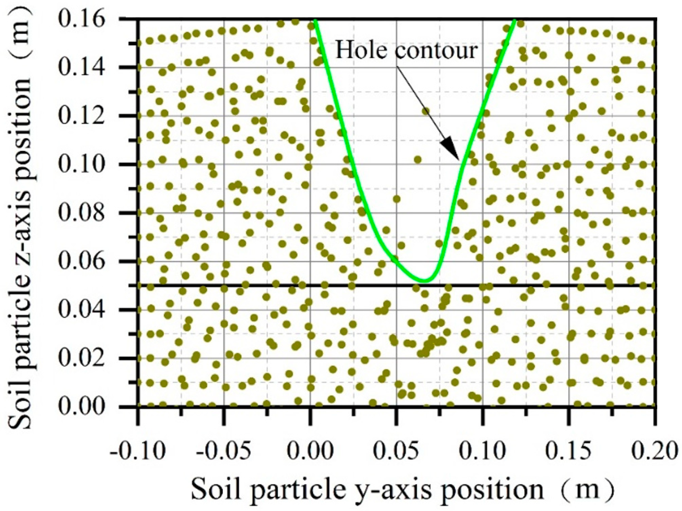
As Figure 24, Figure 25 and Figure 26 indicate, as the soil moves, the seed hole is formed with a width of 120 mm, equal to the desired hole size. The relative deviation rate is 9%, which fully satisfies the technical requirements of potato hole sowing.
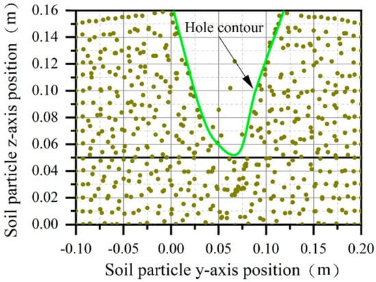
Figure 26.
Soil particle location map.
4. Field Trials
4.1. Test Conditions and Methods
The field performance test of the eccentric coupling hole-drilling and sowing mechanism was conducted in the Sanniu experimental field in Chankou Town, Dingxi, China—see Figure 27 and Figure 28. The experimental land contains yellow loess soil with a flat plot and uniform ridge height and width. The ridge distance was 900 mm, the ridge height was 200 mm, the ridge width was 600 mm, and the moisture content was 12.8%. The forward speed of the test unit was 0.5 , provided by a Lovol-354 tractor. According to agronomic requirements, the theoretical sowing depth of potatoes was 140 mm, and the theoretical hole spacing was 320 mm. After the completion of the work, the performance of the potato seeder was evaluated according to the requirements specified in GB/T 25417-2010 [33] “Technical Conditions for Potato Planting Machines”, NY/T 1415-2007 [34] “Technical Specifications for Quality Evaluation of Potato Planting Machines”, and NY/T 987-2006 [35] “Quality Requirements for Film Mulching and Hole Seeding Machines”. The experimental values of the qualification rate of planting depth under the mulch film, the qualification rate of hole spacing, and the index of repeated and missed seeds were measured.
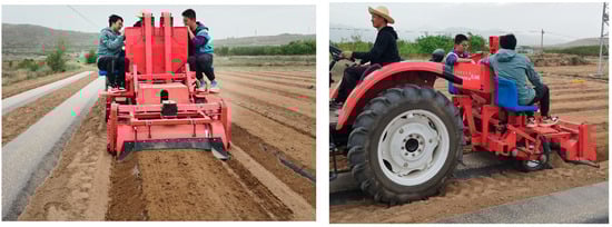
Figure 27.
Field-test photographs.
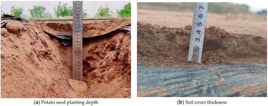
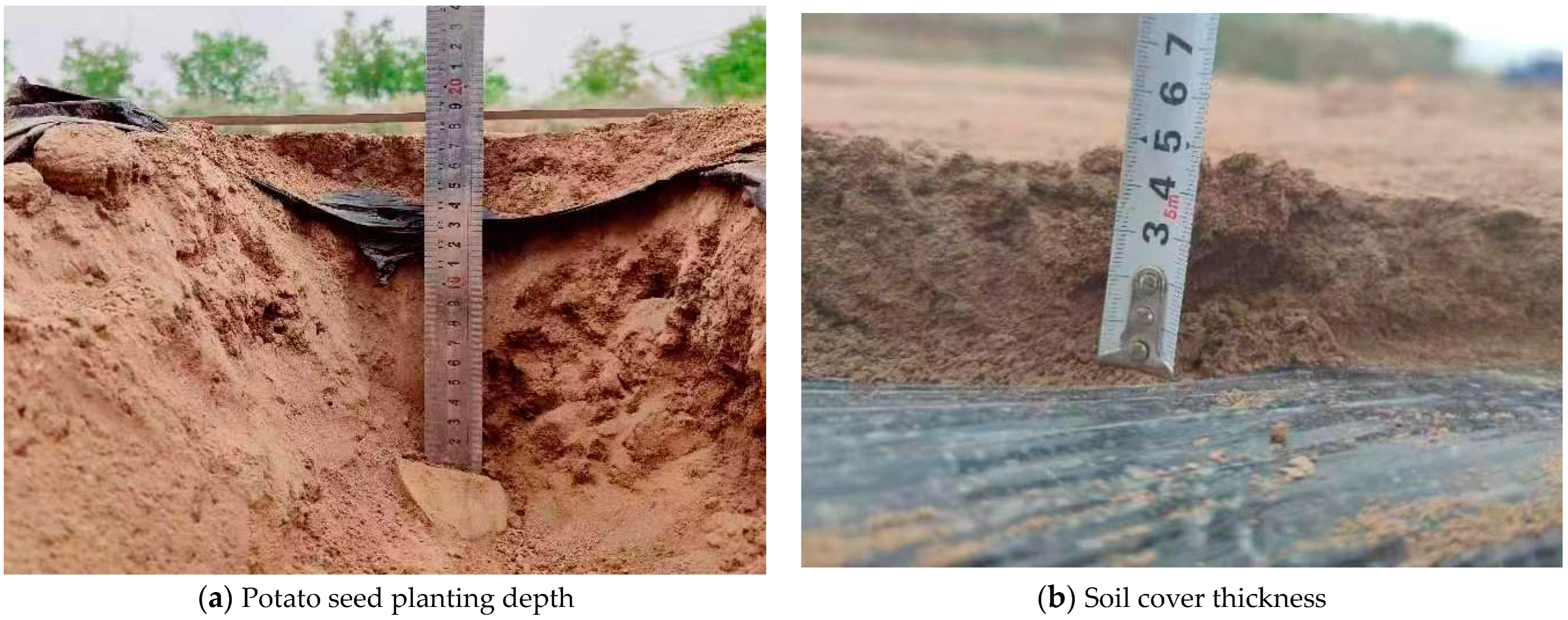
Figure 28.
Measurement of planting depth and soil cover thickness.
To determine the qualification rate of planting depth under the mulch film, hole spacing, and replanting and missed planting indices, the experimental field was divided horizontally and vertically into four equal parts. Two nonadjacent plots were then selected as sample plots, each of which was further equally divided in both the horizontal and vertical directions. Each sample plot was subdivided into five subplots, each with a side length of 4200 mm. Within each subplot, three rows of samples were taken using the planting machine hole as the measurement point, with ten points measured in each subplot. The soil was then cut vertically, and measurements were taken for the planting depth, hole spacing, and the number of sweet potatoes in each hole under the mulch film on the soil plane. The qualification rates of planting depth, hole spacing, and replanting and missed planting indices were calculated as follows:
where ε is the qualification rate of sowing depth under the mulch film, ξ is the qualification rate of acupoint distance, Q is the replanting index, M is the leakage index, and N is the number of qualified holes for sowing depth under the mulch film. According to agronomic requirements, the potato sowing depth under the mulch film is qualified if sowing depth is between 130 mm and 150 mm. M is the number of qualified acupoint distances, and the theoretical acupoint distance is considered qualified if this distance is between 315 mm and 325 mm. represents the number of replants, N represents the total number of holes measured in the experiment, with a theoretical requirement of one potato seed in each hole and at least 95% of hole distances being qualified; is the number of missed species, which means 90% of M is qualified.
The test results are based on the average measurement of eight test areas.
4.2. Experimental Results and Analysis
Using the above measurement and calculation methods, the performance test results of various mechanisms for eccentric combined hole sowing are shown in Table 3.
Table 3.
Results of field performance test.
From the test results in Table 4, it can be seen that all the test indicators of the operation quality of the planting mechanism meet the standard requirements according to the standards GB/T 25417-2010 “Technical Conditions for Potato Seeders”, NY/T 1415-2007 “Technical Specifications for Quality Evaluation of Potato Seeders”, and NY/T 987-2006 “Quality Requirements for Film Covering and Hole Seeders”. During the work process, the planting mechanism was observed to run smoothly.
Table 4.
Comparison table of planting performance.
5. Conclusions
Based on the planting conditions of single- and double-row potato cultivation and the benefits of covering mulch film with soil for promoting growth, an improved potato-planting machine was designed to address these planting conditions and leverage the benefits of mulch film by first laying the mulch film and then planting potatoes. The key components of the prototype were analyzed and designed. This included determining the structure and motion parameters of the spoon-chain seeder, the eccentric coupling mechanism, and the hole-drilling and seeding mechanism. The designed planting device meets the requirements for successful potato cultivation. The eccentric linkage hole-drilling and sowing system, consisting of the hole-drilling device, the sowing device, and the eccentric linkage mechanism, can accurately and quickly sow potatoes, improving planting efficiency. According to field experiments, the potato-planting machine achieved a 92% qualification rate for planting depth under the mulch film, an 88% qualification rate for seed potato spacing, a 98% qualification rate for avoiding overplanting, and a 99% qualification rate for avoiding missed planting. All field performance test indicators met national and industry standards, demonstrating successful planting without tearing the film.
Author Contributions
Conceptualization, W.S.; software, L.P. and P.A.S.; investigation, L.P., W.S. and J.W.; resources, W.S. and P.A.S.; writing—original draft preparation, L.P.; writing—review and editing, W.S., P.A.S., J.W. and L.P.; supervision, J.W. and P.A.S.; project administration, W.S.; funding acquisition, W.S. All authors have read and agreed to the published version of the manuscript.
Funding
This work was supported by the Gansu Provincial University Industry Support Plan (2022CYZC-42), the National Natural Science Foundation of China Grant NSFC (52165028), and the Key Scientific and Technological Program of Gansu Province (22ZD6NA046).
Institutional Review Board Statement
Not applicable.
Data Availability Statement
Data are reported within the article.
Conflicts of Interest
The authors declare no competing interests.
References
- Xia, M. Glimo launches a new traction potato planter. Agric. Mach. Mark. 2024, 53. [Google Scholar]
- Zhang, T. Design and experiment of combined micro-potatoes precision seed metering device with pneumatic scoop. Shandong Agric. Univ. 2022, 2024, 53. [Google Scholar]
- Li, P.; Tian, B.; Sun, W.; Zhang, H.; Liu, X.; Li, H. Development Status and Prospects of Potato Precision Planting Technology. Agric. Equip. Veh. Eng. 2024, 62, 29–33. [Google Scholar]
- Zhao, S. Development of 2BSL-2 Potato Ridge Planter; Mongolia Autonomous Region; Inner Mongolia Agricultural University Agricultural Engineering Complete Equipment Research Institute: Huhhot, China, 2003. [Google Scholar]
- Zhao, J.; Zhang, Y.; Shen, L. Design of 2CMF-2 Potato Planter. Mod. Agric. 2009, 4, 37. [Google Scholar]
- Li, C.; Feng, Y.; Kan, Z.; Liang, R. Development of a single row hanging potato fertilizer planting machine. Jiangsu Agric. Sci. 2013, 41, 369–371. [Google Scholar]
- Liu, W.; He, J.; Li, H.; Li, X.; Liu, P. Design and Experiment of Vibration arranging based seeder for potato microseed. Trans. Chin. Soc. Agric. Mach. 2019, 50, 70–80. [Google Scholar]
- Niu, K.; Fan, Y.; Luo, M.; Liu, Y.; Lv, C.; Fang, X. Design and Experiment of potato metering device with double-deck seed tank. Trans. Chin. Soc. Agric. Eng. 2016, 32, 32–39. [Google Scholar]
- Yang, Y. Design and Experimental Research on Air-Suction. Master’s Thesis, Northeast Agricultural University, Harbin, China, 2017. [Google Scholar]
- Hou, J.; Liu, W.; Zhang, W.; Lv, J.; Lv, Z.; Zhang, Z. Design of Pneumatic cup seed-metering device for Potato. Trans. Chin. Soc. Agric. Eng. 2018, 34, 18–28. [Google Scholar]
- Wang, G.; Sun, W.; Zhang, H. Research on a kind of seeding-monitoring and compensating control system for potato planter without additional seed-metering channel. J. Comput. Electron. Agric. 2020, 177, 105681. [Google Scholar] [CrossRef]
- Sun, W.; Wang, G.; Wu, J. Design and experiment on loss sowing testing and compensation system of spoon-chain potato metering device. J. Trans. Chin. Soc. Agric. Eng. 2016, 32, 8–15. [Google Scholar] [CrossRef]
- Wang, G.; Sun, W. Development of a kind of potato loss sowing detection and compensation device. J. Res. Agric. Mod. 2016, 37, 1008–1014. [Google Scholar]
- Shi, L.; Wu, J.; Zhao, W.; Sun, W.; Zhang, F.; Sun, B. Establishment and parameter verification of farmland soil model in uniaxial compression based on discrete element method. J. China Agric. Univ. 2015, 20, 174–182. [Google Scholar]
- Niu, L.; Zhou, L.; Yuan, Y. Design and experiment on automatic compensation system of spoon-chain potato metering device. J. Trans. Chin. Soc. Agric. Mach. 2016, 47, 76–83. [Google Scholar]
- Wang, G.; Sun, W.; Chen, D. Realization of an integrated seeding and compensating potato planter based on one-way clutch. J. Int. J. Agric. Biol. Eng. 2020, 13, 79–87. [Google Scholar] [CrossRef]
- Lv, J.; Yang, Y.; Li, Z. Design and experiment of cup-belt type potato seed-metering device. J. Trans. Chin. Soc. Agric. Eng. 2016, 32, 17–25. [Google Scholar]
- Dai, F.; Xin, S.; Zhao, W.; Liu, F.; Xin, B.; Ma, M. Design and experiment of combined potato planting machine for covering soil on top of full surface. J. Trans. Chin. Soc. Agric. Mach. 2017, 48, 76–83. [Google Scholar]
- Wang, Y.; Yang, Z.; Li, X.; Yang, H.; Kou, M. Design and experiment of vertical submerged corn hole seeder based on parallel four-bar linkage mechanism. J. Chin. Agric. Mech. 2022, 43, 18–24. [Google Scholar] [CrossRef]
- Cui, R.; Jian, S.; Xv, W.; Ma, J.; Wang, X. Design and test of garlic upright plant. J. Agric. Mech. Res. 2016, 38, 201–205. [Google Scholar] [CrossRef]
- Cui, R.; Zhang, H.; Xv, W. Discussion on the present situation and development of garlic mechanized production in China. J. Agric. Mech. Res. 2015, 37, 83–86. [Google Scholar] [CrossRef]
- Shi, F.; Sun, S.; Deng, X.; Wang, J. Trajectory analysis of planting device of eccentric disc and finger clip pattern seedling planting machine. J. Hunan Agric. Univ. 2012, 38, 333–336. [Google Scholar] [CrossRef]
- Cui, R.; Wang, X.; Xin, J.; Sun, L.; Wu, C. Desing and test of arc duck-billed garlic seed planter. J. Int. J. Agric. Biol. Eng. 2022, 53, 120–130. [Google Scholar]
- Sun, W.; Liu, X.; Wang, H.; Zhang, H.; Wu, J.; Yang, X.; Wang, G. Design and test of double crank multi-rod hill-drop potato planter on plastic film. J. Trans. Chin. Soc. Agric. Eng. 2018, 34, 34–42. (In Chinese) [Google Scholar] [CrossRef]
- Li, Y.; Liu, M.; Duan, R. Design of complete machine and key components of potato planter. J. Agric. Eng. 2022, 12, 95–102. [Google Scholar] [CrossRef]
- Fang, H.; Ji, C.; Farman, A.; Guo, J.; Zhang, Q.; Chaudhry, A. Analysis of soil dynamic behavior during rotary tillage based on distinct element method. J. Trans. Chin. Soc. Agric. Mach. 2016, 47, 22–28. [Google Scholar]
- Tan, H.; Xv, L.; Ma, S.; Niu, C.; Yan, C.; Shen, C. Design and experiment of scraper organic fertilizer strip spreading and rotary tillage mixed fertilizer applicator. Trans. Chin. Soc. Agric. Mach. 2022, 11, 163–175. [Google Scholar]
- Liao, Q.; Du, W.; Zhang, Q.; Lin, J.; Chen, Z.; Zhang, J. Design and experiment of cigar tobacco adjustable seed-plot ridging and film spreading machine. Trans. Chin. Soc. Agric. Mach. 2022, 11, 116–126. [Google Scholar]
- Sun, J.; Liu, Q.; Luo, P.; Yang, F.; Liu, Z.; Wang, Z. Soil erosion law of contour rotary tillage of hillside tractor on sloping land. J. Trans. Chin. Soc. Agric. Mach. 2022, 53, 44–56. [Google Scholar]
- Chen, B.; Chen, X.; Chen, X.; Zhu, J.; Yu, Q.; Miao, Y.; Liu, Y. Design and experiment of crawler self-propelled ridging and fertilization combined machine for strawberry. J. Chin. Agric. Mech. 2022, 43, 55–60. [Google Scholar]
- Shi, B.; Sun, W.; Zhao, Z. Design and experiment of the combined machine for transplanting outcrop of codonopsis with micro ridge covered with film. J. Appl. Sci. 2023, 13, 9149. [Google Scholar] [CrossRef]
- Jing, W.; Wang, S.; Qian, H. Simulation analysis of cutting soil by weeding claws between plants in paddy field based on LS-DYNA. J. Agric. Mech. Res. 2023, 45, 203–209. [Google Scholar] [CrossRef]
- GB/T 25417-2010; Potato planting machine-Specifications. Standards of China: Beijing, China, 2010.
- NY/T 1415-2007; Technical Specification for Quality Evaluation of Potato Planter. Standards of China: Beijing, China, 2007.
- NY/T 987-2006; Operation Quality of Film Mulching Hole Seeder. Standards of China: Beijing, China, 2006.


Disclaimer/Publisher’s Note: The statements, opinions and data contained in all publications are solely those of the individual author(s) and contributor(s) and not of MDPI and/or the editor(s). MDPI and/or the editor(s) disclaim responsibility for any injury to people or property resulting from any ideas, methods, instructions or products referred to in the content. |
© 2024 by the authors. Licensee MDPI, Basel, Switzerland. This article is an open access article distributed under the terms and conditions of the Creative Commons Attribution (CC BY) license (https://creativecommons.org/licenses/by/4.0/).