Article

Comparison and Experimental Study of Cotton Stalk Extraction via Nip Roller Based on Nip Motion Trajectory Equation

1
College of Electromechanical Engineering, Xinjiang Agricultural University, Xinjiang Uygur Autonomous Region, Urumqi 830052, China
2
Xinjiang Key Laboratory of Intelligent Agricultural Equipment, Xinjiang Uygur Autonomous Region, Urumqi 830052, China
3
Nanjing Institute of Agricultural Mechanization, Ministry of Agriculture and Rural Affairs, Nanjing 210014, China
*
Author to whom correspondence should be addressed.
Agriculture 2024, 14(6), 950; https://doi.org/10.3390/agriculture14060950
Submission received: 27 May 2024 / Revised: 10 June 2024 / Accepted: 10 June 2024 / Published: 18 June 2024
(This article belongs to the Section Agricultural Technology)

Abstract

:
In the field of straw recycling, a cotton straw-harvesting mechanism is an important piece of agricultural equipment. The mechanistic analysis method of the harvesting mechanism is a major focus of research and development in this field. Currently, in the mechanistic analysis of the cotton straw recycling mechanism, the kinematic and mechanical analysis of the recycling mechanism is generally the main focus. There is not a lot of research based on the quantitative analysis between different recycling mechanisms. In this study, a clamped cotton straw pulling mechanism is optimized and designed, and two different pulling structures are designed. In addition, a two-dimensional modeling and analysis method is used to establish the two-dimensional equations of motion of the two pulling mechanisms, analyze the leakage and breakage rates of the two clamping structures, predict the final pulling effect, and verify the results of the field tests. According to the analysis, the belt-clamping side has more uniform clamping stress and a larger clamping contact area than the chain-clamping side, and the tangential stress on cotton straw is smaller. Based on the field-test verification, the band-clamping side had a higher pulling net rate by an average of 19.32% and a lower missed pulling rate by an average of 6.01% than the chain-clamping side. Therefore, it was determined that the main reason for the lower pulling net rate of the chain-gripped side than that of the belt-gripped side was the higher pulling breakage rate, and the secondary reason was the high leakage pulling rate. Thus, the feasibility and accuracy of the analytical method of this study are verified.

1. Introduction

Cotton straw-harvesting machinery is a key mechanical recycler in the secondary utilization of cotton straw and, according to the harvesting method, is divided into the opposite row type and the non-opposite row type. Its performance has a direct impact on the economic efficiency of the secondary utilization of straw within the industry. At present, the whole-straw-pulling mechanism has achieved certain results and is mostly based on the roller type worldwide, of which the most representative is the roller-type cotton straw-harvester of Australia and the AMADAS cotton straw-harvester of America. The basic principle is to utilize a pair of relatively rotating tires or rubber sticks to achieve the whole-straw-recycling operation of cotton straw. This kind of mechanism easily misses pulling due to the feeding-angle problem when starting to pull. The Nanjing Agricultural Mechanization Research Institute of China has developed a toothed-plate cotton straw-harvesting machine, the basic pulling principle of which is to use a kind of toothed plate to hold the cotton straw at a certain angle. This mechanism easily leads to an increase in the pulling and breaking rate due to the structure of the toothed plate [1,2].
The mechanistic study of the cotton straw-harvesting mechanism is the basis of cotton straw-harvesting machinery design. At present, the cotton straw recovery mechanism analysis is generally based on the kinematic analysis and mechanical analysis of the recovery mechanism [3]. Among them, a kinematic analysis is the calculation of the velocity of the cotton straw subjected to the action of the lifting mechanism. The mechanical analysis of the cotton straw using the clamping mechanism is used to complete the pulling role for the mechanical analysis of the force point [4]. This method can describe the basic design parameters of the mechanism, but in the subsequent theoretical study of the mechanism, it is not possible to compare the kinematic analysis of the cotton straw and the internal stress of the straw in different mechanisms.
In order to address the above problems, this study takes a pair-clamping cotton straw-harvester as the research object, uses two different contact materials, analyzes the straw-harvesting mechanism under different motion trajectories, and establishes a mathematical model of the motion of straw in a two-dimensional plane. The Burgers rheological model was used to describe the deformation state of fresh cotton straw in the cotton field under the clamping force of the harvesting mechanism. We compared the advantages and disadvantages of the two mechanisms through pull-off analysis and leakage analysis and verified the theoretical analysis results through field trials [5,6].

2. Materials and Methods

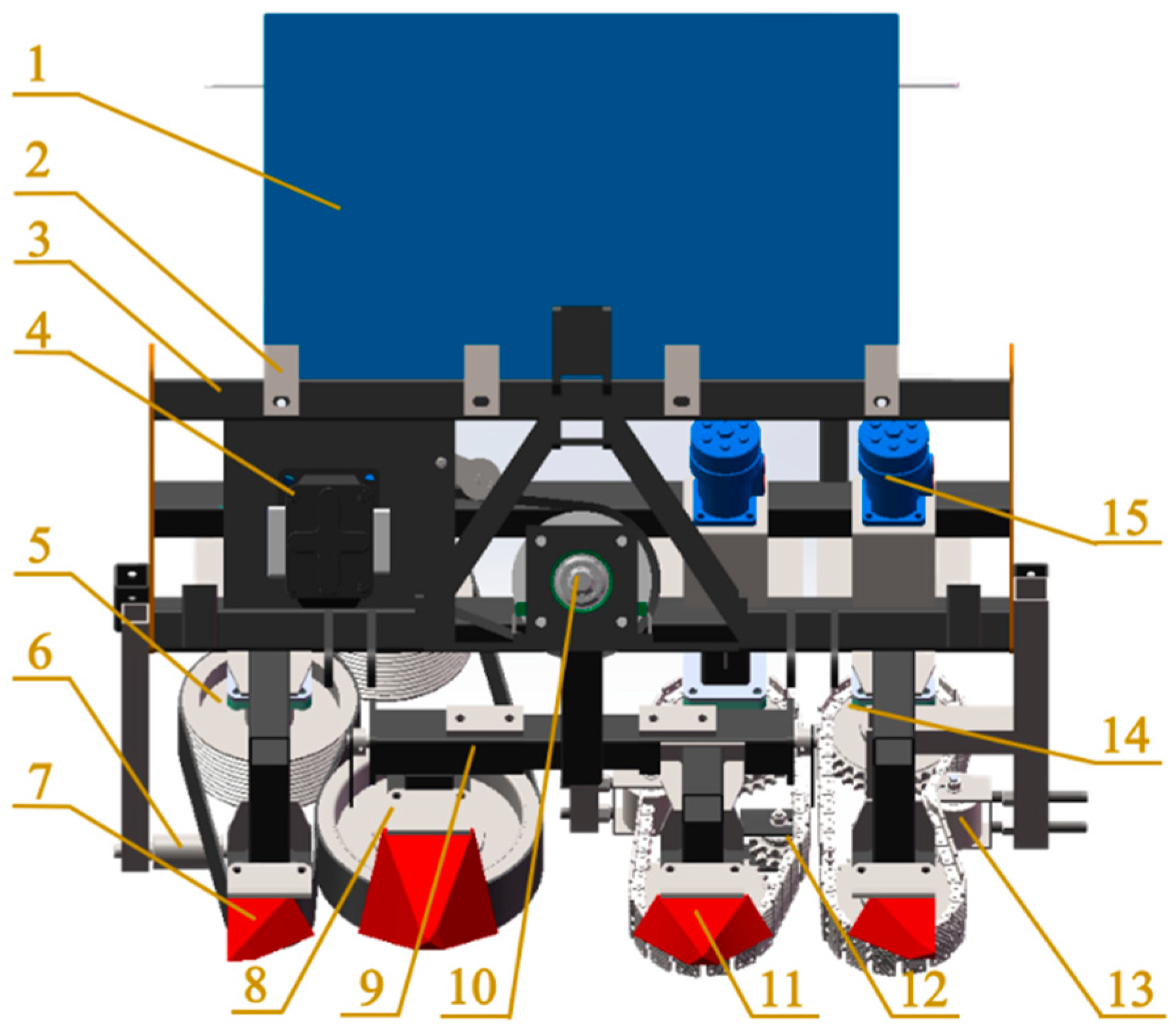
2.1. Design of Machine Structures

In this study, cotton straw-harvesting equipment is optimized and designed, as shown in Figure 1. The mechanical equipment’s harvesting mode for opposite-row harvesting and the feeding structure size, according to the Xinjiang cotton field in the opposite-row planting mode (660 mm + 110 mm + 660 mm), determines the tractor’s power output shaft, providing power to the pulling mechanism of the hydraulic pump. Then, the hydraulic pump drives the hydraulic motor for the working parts to provide power. The working parts of this mechanism include a flexible belt-clamping type on one side, clamped by two sets of wrapping belts of staggered design. Two sets of pulleys on the clamping side of the belt are staggered, and the tension can be adjusted through the telescopic frame in the middle of the mechanism. On the other side is a chain-clamping type with flexible rubber, and the clamping part is a double-row chain with a clamping plate. The four clamping sprockets are symmetrically placed to improve the clamping force, and the front sprocket of the inside can be adjusted to the feed through the connecting telescopic frame. The inner front sprocket can be adjusted for feed width by means of a connected telescopic frame. In the center, there is a thread-adjustable tensioning sprocket as a tensioning mechanism. The lifting angle of both chain-clamping mechanisms is 45°, which can complete the clamping, lifting, and throwing operations of the lifting mechanism on cotton straw at the same time [7].
The main technical parameters of this pair-clamped cotton straw puller are shown in Table 1.

2.2. Two-Dimensional Path Equation Planning and Stem Deformation Analysis for Institutions

The advantages and disadvantages of the two kinds of clamping structure paths are compared through mathematical modeling. The two-dimensional trajectory equations of the two kinds of clamping paths are used for trajectory planning and simulation. The better simulation results of the two kinds of clamping paths are obtained through the belt and chain tension and the structural tension; the instantaneous direction of the movement of the cotton stalks at any clamping point in the clamping paths is obtained through the solving of tangent equations of the two-dimensional clamping paths mathematical model. The deformation of cotton straw in the clamping path is analyzed to obtain the deformation relationship equation. The next step was to establish the rheological mathematical model of cotton straw, take the Burgers rheological mathematical model as a reference to establish the relationship equation of the rheological mathematical model of cotton straw, solve the motion state of cotton straw in the two kinds of clamping paths, and carry out a detailed analysis of the state of cotton straw in the mechanism and make a prediction of the working effect of the mechanism [8].

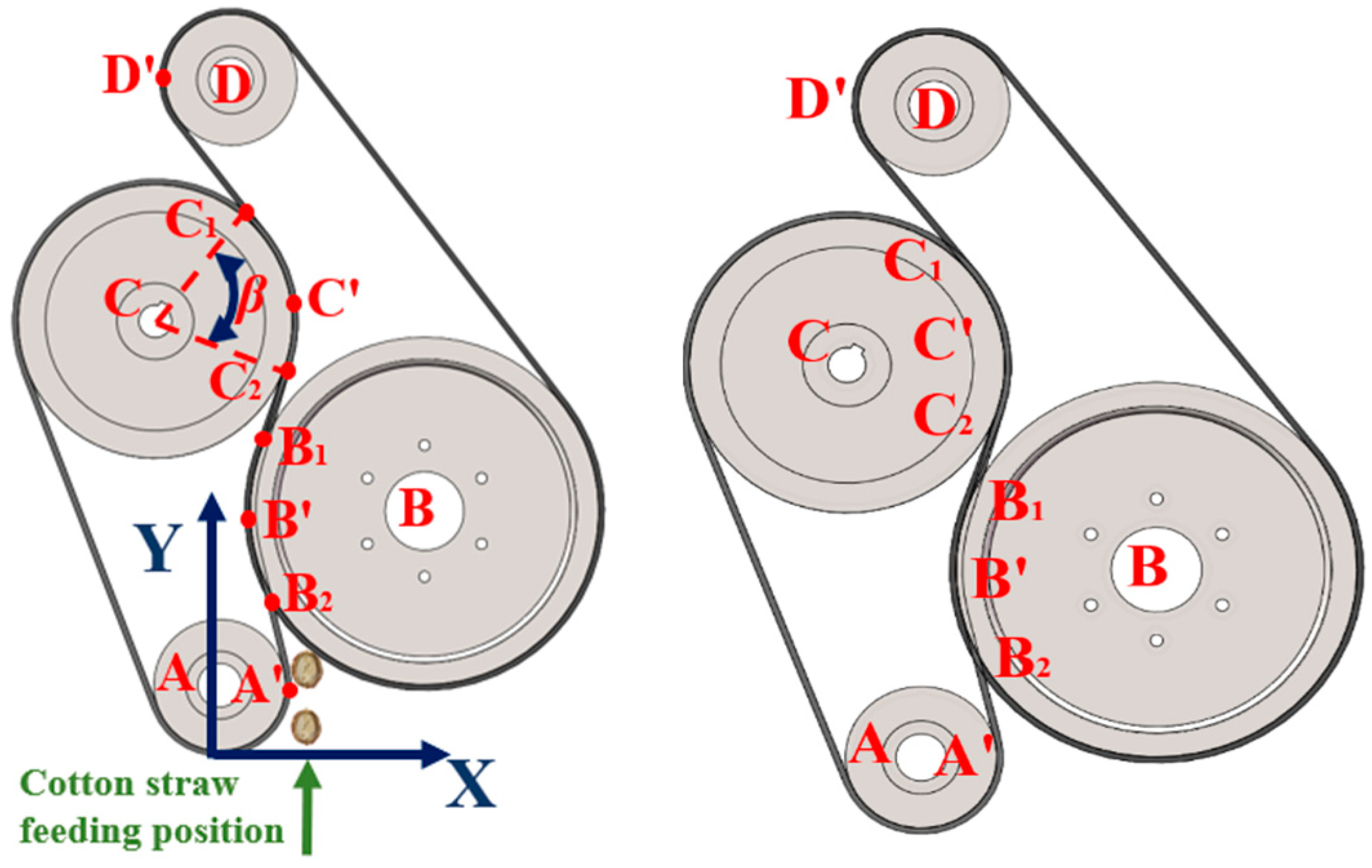
2.2.1. Clamping Trajectory Planning

By calculating the allowable range of the clamping path trajectories of the belt-clamp side and the chain-clamp side, the transient dynamics simulation of the clamping structure is carried out by using the Transient structural module in Workbench to obtain the better trajectory paths of the two clamping modes, and the theoretical analysis is carried out to obtain the optimal harvesting mode of the clamping trajectories of the two clamping modes.
According to the reference of cotton straw bending load test of previous researchers, in the experiment, the acceptable bending damage displacement of cotton straw of 60 mm length in the near-ground part is about 13 mm–15 mm, and the maximum curvature that cotton straw can withstand under the established coordinate system is calculated to be about 25–30. The average value is taken. According to the principle of safety design, the safety coefficient is taken to be 2 under the condition that the maximum curvature of the permissible straw is about 13.5 [9], according to the following formula:
C m a x = 1 R
Cmax: maximum curvature of cotton straw when subjected to clamping;
R: instantaneous radius of curvature of cotton straw under bending damage loads.
Two kinds of key working parts of the clamping mechanism are simplified in the three-dimensional model, as shown in Figure 2a,b. The cotton straw clamping path in Workbench for many transient dynamic simulations is used in order to ensure that the cotton straw can be a whole straw to complete the harvesting movement of the whole process based on the cotton straw movement clamping path for analysis and comparison. The transverse mid-point of the movement of the path is taken as a numerical value of the collection of the line [10], the belt strain, and the stress of the situation in the statistical analysis of data to analyze, compare, and obtain the most ideal clamping trajectory.
The two clamping force distributions on the better clamping path are obtained as shown in Figure 3a,b, where the X-axis and Y-axis form a plane to express the two-dimensional trajectory of the motion clamping path. The Z-axis expresses the clamping stress force on the straw by the clamping structure on the motion path, where the unit is MPa.
According to the two kinds of clamping force graphs, it can be seen that the belt-clamping side in the feeding stage of the clamping stress change is relatively smooth, the maximum clamping stress is about 259 MPa, and the whole path can be maintained at more than 48 MPa clamping stress, which can ensure that the whole path of the clamping has a certain amount of cotton straw clamping stress, so as to reduce the rate of pull-off and leakage pull-off. The chain-clamping side of the clamping stress at the feeding point changes dramatically. The maximum clamping stress at the feeding point is about 305 MPa, which leads to a higher pull-off rate, and the clamping stress in the whole path of the movement except for the clamping point and tensioning point is only about 20 MPa, so there is not enough clamping stress to ensure a low leakage pull-off rate except for the feeding point and the tensioning point, which leads to a reduction in the pull-off rate [11]. From the viewpoint of clamping material, the flexible clamping method of belt clamping has a distributed force load compared with the rigid clamping of the chain plate, which is less destructive to the cotton straw, so the two-dimensional clamping force simulation shows that the belt-clamping side has a greater advantage over the chain-clamping side regarding cotton straw pulling.

2.2.2. Calculation of 2D Path Parameters with Clamping Mechanism

The belt-clamping mechanism includes two groups of staggered arrangement of the pulleys for the working wheel, establishing the Cartesian two-dimensional right-angle coordinate system to the front of the mechanism of the small belt wheel of the advancing direction and the intersection of the horizontal tangent as the origin, the horizontal tangent for the x-axis direction, and the direction of the cotton straw feeding direction for the y-axis direction. The use of segmentation analysis method, the two-dimensional coordinate system, and the cotton straw movement trajectory path can be simplified into an S-shaped curve of three segments of B1B2, B1C2, and C1C2, of which B1B2 segment and C1C2 segment can be regarded as a circular arc, and B1B2 segment arc angle is set as α. The arc angle of C1C2 segment is set as β. Segmented equations can be used to express the two-dimensional plane of the cotton straw trajectory of the clamping mechanism, and its working parts layout is shown in Figure 4.
As shown in Figure 5, since the average diameter of cotton straw is about 10 mm, the diameter of clamping pulley is about 317 mm and can be used to determine the cotton straw feeding point B2 and thus the coordinates of the belt-clamping feeding point B2 (63.6, 142.3) [12].
According to the geometric arrangement of the mechanism and the structural dimensions of the parts, the coordinates of each key point can be calculated in the two-dimensional coordinate system, including A′ (60, 60), B′ (62.1, 165.9), C′ (125, 397.5), and D′ (112.1, 597.5). Point B2 is the feeding point of the contact between the cotton straw and the mechanism, point B2 is the contact feeding point of cotton straw and mechanism, according to the belt thickness of 10 mm, B pulley radius of 158.5 mm, C pulley radius of 125 mm. Geometric analysis and calculation can be used to determine the B2 and C2 points in the two-dimensional coordinate system coordinates of B2 (63.6, 142.3) and C2 (115.98, 351.28), and the angle of two parts of the circular arc path are α = 17 °; β = 43.4°.
According to the above calculations, the equation of the three-segment trajectory in the two-dimensional coordinate system can be obtained as
B1B2:
x 220.9 2 + y 165.9 2 = 158.8 2
6.67 y 885.54 < x < 6.67 y + 1327.57
B1C2:
x = 0.32 y + 2.25
63.6 < x < 189.5
C2C1:
x 2 + y 397.5 2 = 125 2
2.51 y + 997.72 < x < 2.51 y 997.72
Curvature is the rate of rotation of the tangent direction angle to the arc length for a point on a curve, defined by differentiation, and indicates the extent to which the curve deviates from a straight line. Mathematically, it is a numerical value that expresses the degree of curvature of a curve at a given point [13]. The equation for its calculation is
C 1 = y 1 + y 2 3 2
A list of variables follows.
C1: curvature;
y: independent variable of an equation.
Formulas (2)–(4) can be introduced into Formula (5) to calculate the comparison and obtain the maximum curvature value of the band clamp side C1max = 8. In Formulas (2)–(4) in the x derivation, we can obtain y1′, y2′, and y3′, and y1′, y2′, and y3′ are subtracted from the comparison to obtain the maximum change in slope value. The band clamp side of the maximum slope of 0.32 is obtained according to the geometric calculations of the maximum clamping path of the working length L1 = 346.16 mm.

2.2.3. The 2D Path Calculation for Sprocket Clamping Mechanism

Chain-clamping mechanism side for the two sets of sprocket clamping structures is seen in Figure 6. For sprocket A in the cotton straw feeding side and the horizontal tangent point for the origin, the horizontal direction is set as the x-axis direction, the cotton straw feeding direction is set as the y-axis direction, and there was the establishment of Cartesian two-dimensional Cartesian coordinate system according to the force analysis of the clamping side of the chain-clamping force peak point for the three points A′, E′, and C′. Here, E′ is used as the demarcation point for the segmented simplification of the clamping movement path to set up two-dimensional Cartesian coordinate system.
As shown in Figure 6, the cotton straw feeding motion trajectory is simplified into idealized line segments of two parts, A′E′ and E′C′, from which the equation of the cotton straw motion trajectory on the chain-clamping side can be obtained as
AE′:
x = 0.374 y + 59 0 < y < 224.25
E′C′:
x = 0.033 y + 135.45 224.25 y 431.51
The above two equations can be brought into (5). According to the formula theorem, the curvature of the straight line C1max = 0. Derivation of x in Equations (6) and (7) means the slope of the two line segments is subtracted, yielding the maximum slope change of K2max = 0.341. According to the geometric relationship, we calculated the longest path of the movement of the cotton straw in the sprocket-gripping side of the longest path of the cotton stalks L2 = 289.795 mm.
Comparing the above calculation results, in terms of curvature, the curvature of the belt-clamping side is C1max = 8. The chain-clamping side can be simplified as two straight lines. According to the definition of the curvature being 0, combined with the clamping force simulation analysis and the flexible clamping factors, we can see that the change of the clamping force near the feeding point of the belt-clamping side is gentle, and the change of the curvature in the full path of the clamping can be a bigger clamping force for the straw. The curvature of the belt-clamping side can be changed. The chain-clamping side has rigid clamping because the clamping structure only has large clamping force at the feeding point and tensioning point and the clamping force changes sharply near the feeding point. The clamping force on the rest of the trajectory line is generally lower than that of the chain-clamping side; in terms of the change in slope, the maximum change in the slope calculated for the belt-clamping side is 0.32, and the change in the slope for the chain-clamping side is 0.341. Compared with the maximum change in the slope of the two clamping paths, the change in the slope of chain clamping is 6.56% greater than that of the belt-clamping side. It is calculated as follows:
P = k 2 m a x k 1 m a x k 1 m a x
A list of variables follows.
P: ratios;
k1max: with clamping-side slope;
k2max: chain-clamping side slope.
In terms of working path length, the clamping path length of the belt-clamping side is L1 = 346.16 mm, and the clamping path length of the chain-clamping side is 19.45% greater than the maximum clamping path of the chain-clamping side compared to that of the belt-clamping side, which is calculated by the following formula:
P = L 2 L 1 L 1
A list of variables follows.
P: ratios;
L1: with clamping side path length, mm;
L2: with clamping side path length, mm.
In the mathematical curvature model, slope and movement trajectory under the clamping stress analysis of the two plucking structures show that in the S-shaped plucking path with the clamping side of the belt for flexible clamping, the movement path is long; the whole movement trajectory on the homogeneous clamping stress is greater [14]; the clamping stress change at the feed point is smooth; the cotton straw wrapped in the clamping with a more uniform distribution of the wrapping clamping stress, reducing the plucking rate; the chain-clamping side of the trajectory has straight-line clamping; the clamping stress changes sharply at the feed point and with rigid clamping; the cotton straw has rigid clamping; and greater clamping stress on the clamping path only occurs at the clamping point and the tensioning point. The chain-clamping side trajectory is linear clamping, the clamping stress changes sharply at the feeding point and with rigid clamping, the cotton stalks are rigidly clamped, the clamping path is only in the sprocket clamping point, and the tension point has a larger clamping stress [15]. Compared with the S-shaped trajectory, clamping path is short. Therefore, in the two-dimensional right-angle coordinate system calculation, it can be seen that the belt-clamping structure is more advantageous than the chain-clamping structure.

2.3. Two-Dimensional Path Equation Planning and Stem Deformation Analysis for Institutions

2.3.1. Cotton Straw Deformation Analysis

Under the action of the clamping mechanism, the cotton straw follows the S-type movement route in both clamping modes. The belt-clamping side, as an example, is shown in Figure 7.
Where FN1 is the belt-clamp squeezing force exerted on cotton stalks (N), FN2 is the chain-clamping squeezing force exerted on cotton stalks (N), and v is the feed direction (m/s).
The force bending moment of the stalk is
E s I s d 2 y d x 2 = F 1 L 2 L 3
A list of variables follows.
Es: the modulus of elasticity of cotton straw, MPa;
F1: squeezing force exerted by the mechanism on the cotton stalks, N;
L2: total length of stalks after deformation, mm;
L3: total length of stem deformation, mm;
IS: stalk moment of inertia, mm.
The deformation deflection ∆y of the stalk after clamping can be calculated by integrating the collation of Equation (10):
y = F 1 L 2 L 1 L 3 6 E s I s
L1: stem length before deformation, mm.
Stem morphology variables should satisfy
D = F N β < D m a x
A list of variables follows.
D: stem morphology, mm;
β: stalk deformation compression factor;
Dmax: stalk transverse compression destroys deformation, mm.
In both clamping mechanisms, the chain-clamping side is rigid clamping, the clamping force on cotton straw is FN, and the belt-clamping side is expressed by the homogeneous force equation:
F N = q L
A list of variables follows.
q: homogenized load on cotton straw with clamping side, N·mm−1;
L: contact length of the clamping side of the belt to the cotton straw, mm.

2.3.2. Rheological Modeling and Development

The movement process of cotton straw has certain rheological and viscoelastic properties, which can be described by a Burgers rheological model containing elastic and viscous units as well as a pair of independent elastic and viscous unit components on both sides of the distribution [16]. The modeling of the rheostat is shown in Figure 8.
Based on the input force Fi(t) and deformation response xi(t) in each layer, combined with Equation (10), the intrinsic equations of the overall contact force F(t) of the cotton straw stalk and the overall deformation variable x(t) of the stalk are calculated.
b 2 x ¨ t + b 1 x ˙ t = a 2 F ¨ t + a 1 F ˙ t + F t
including
b 2 = c 2 c 3 k 2
b 1 = c 3
a 1 = c 3 k 1 k 2 + k 0 c 2 k 1 + c 3 k 1 + c 3 k 2 k 1 k 2 k 0
a 2 = c 2 c 3 k 1 + k 0 k 1 k 2 k 0
A list of variables follows.
k1: Instantaneous elasticity coefficient, N/mm;
k2: Delay elasticity coefficient, N/mm;
c2: parallel coefficient of adhesion, N·s/mm;
c3: tandem viscosity factor, N·s/mm.
According to the rheological model used to analyze the relationship between the input force and the deformation of the stalks, it can be seen that the belt-clamp side is mainly homogeneous load, and the chain-clamp side is mainly centralized load, which leads to a higher F(t) on the chain-clamp side. Thus, the deformation of the straw cross-section is too great, leading to it easily pulling off.

2.3.3. Leakage and Breakage Analysis

The main reasons for the leakage of the belt-clamping side are low friction coefficient of the belt, resulting in relative sliding, and pulling force being less than the cotton straw root system and the soil bonding resistance, resulting in relative sliding. According to the previous tension stress simulation results, it can be seen that on the chain-clamping side, the lower clamping stress in the clamping paths other than the feeding and tensioning points is the main reason for the leakage of cotton straw plucking. The clamping state of the chain plate clamping friction is less than the cotton root and the soil bonding resistance [17].
We next analyzed the conditions of cotton straw clamping and pulling. Cotton straw enters the clamping area through the action of the grain separator, is clamped by the belt or chain plate at the clamping point, and produces the pulling force on the cotton straw through friction. As shown in Figure 9, the belt clamping and pulling friction on cotton straw are N1 and f1, respectively, and the chain clamping and pulling friction on cotton straw are N2 and f2, respectively.
f 1 = μ 1 N 1 f 2 = μ 2 N 2
A list of variables follows.
μ1: belt-to-straw friction factor;
μ2: coefficient of friction between plywood and cotton straw.
The condition that the cotton straw can be fed by the side mechanism with clamping is satisfied as
N 1 + N 2 sin θ 1 + f 3 cos θ 1 < f 1 + f 2 cos θ 1
A list of variables follows.
θ1: positive pressure on cotton straw from belt-clamping side belt and feeding direction angle, °;
N3: cotton stalk pulling resistance, N;
f3: institutional thrust on cotton straw, N.
The condition that the cotton stalks can be completely pulled up by the clamping side of the band is satisfied as follows:
f 1 + f 2 cos θ sin 45 ° > N 3
Similarly, the chain-clamp side is used to establish the straw mechanics coordinate system, as shown in Figure 10. The cotton stalks can be fed by the following band-clamp side conditions:
N 1 + N 2 sin θ + f 3 cos θ < f 1 + f 2 cos θ
The conditions under which cotton stalks on the chain-clamp side can be completely lifted are
f 1 cos θ 2 sin 45 ° + f 2 cos θ 2 sin 45 ° > N 3
Below is a list of variables.
θ2: positive pressure of chain-clamp side chain plate on cotton straw and angle of feeding direction, °;
f3′: institutional thrust on cotton straw, N.
Cotton stalk breakage mainly occurs in the plucking stage. The two clamping mechanisms’ main reasons for this result are the combination of the plucking force on the cotton stalks and the cotton root and soil bonding force being greater than the cotton stalks’ tensile damage load. Due to the plucking process of friction in the horizontal direction of the force on the cotton stalks, the tangential force is too large, resulting in the cotton stalks being sheared off.
According to the study, the maximum resistance of cotton straw pulling is about 850 N. The clamping point of the machine is about 80 mm above the horizontal ground, and the minimum tensile breaking load below 300 mm above the ground at the root of the cotton straw is 1304 N, which is greater than the resistance of cotton straw pulling. Thus, the cotton straw will not be pulled off.
According to the study, the cotton straw was subjected to bending damage loads averaging between about 23.5 and 27 MPa, and the cotton straw was subjected to two kinds of advection to produce deformation, as shown in Figure 11 [18].
When the width of the belt on the belt-clamp side is 100 mm and the width of the clamping chain plate on the chain-clamp side is 80 mm, then the contact area between the cotton stalks on the belt-clamp side and the belt in the clamping process is 100d1, the clamping angle is 45°, and the contact area between the chain plate on the chain-clamp side and the cotton stalks is 80d2. The condition that the cotton stalks on the belt-clamp side are not damaged by the tangential direction is
f 1 + f 2 cos θ 1 100 d 2 cos 45 < q f 1 sin θ 1 + N 1 cos θ 1 100 d 2 < q
Below is a list of variables.
d1: belt clip side belt to straw contact line length, mm;
q: cotton stalk bending damage load, MPa.
Similarly, the condition that the cotton stalks on the chain-clamp side are not tangentially destroyed is
f 1 + f 2 cos θ 2 80 d 2 cos 45 ° < q f 1 sin θ 2 + N 1 cos θ 2 80 d 2 < q
including
d2: Length of contact line between chain-clamp side plate and straw, mm.
According to Equations (23) and (24), it can be seen that in the clamping-up stage, the contact area between the two clamping mechanisms and the cotton straw is inversely proportional to the destructive load of the cotton straw. In the feeding stage, the cotton straw is subjected to a successful feeding rate, which is directly proportional to the friction of the two clamping mechanisms on the straw. In the feeding stage, the chain-clamp side has a lower feeding success rate than the belt-clamp side, resulting in a higher miss-pulling rate, and in the pulling stage, the chain-clamp side has a higher cutting stress on the straw than the belt-clamp side, resulting in a higher pulling-off rate.

2.4. Field Trial Validation

Indicators and Methods of Testing

The test site was located in Yuli County, Bayin’guoleng Mongol Autonomous Prefecture, Xinjiang Uygur Autonomous Region. The soil was sandy, with a Dongfeng 1404 tractor (with a nominal engine power of 100 kW). The experimental site was planted in a one-film, four-row planting pattern, and the cotton variety was Xinlu Early 45, with a wide row spacing of 100 mm, a narrow row spacing of 660 mm, a plant spacing of about 50 mm, and a plant height of 800 mm. The soil water content ranged from 9% to 21%, the soil firmness ranged from 3.5 to 5.5 kg/cm3, and the cotton stalks’ water content ranged from 15% to 30%.
The test was conducted with reference to GB/T8097-2008, “Test Methods for Harvesting Machinery Combine Harvester”. A piece of cotton land was selected with flat terrain and good cotton growth. When conducting the test, the level of each parameter of the two types of plucking mechanisms was adjusted, ensuring the consistency of each parameter of the two types of plucking mechanisms and keeping the implements advancing at a uniform speed during the process of pulling culms. After adjusting the parameters, every 20 m of the machine moving forward was a group of tests, before and after 5 m as a transition section [19]. Before operation, the number of cotton stalks in the rows of the two pulling structures in the middle 10 m of the 20 m length to be operated was recorded as W1 for the belt-clamping side and W2 for the chain-clamping side. The number of pulling breaks W11 on the belt-clamping side and W21 on the chain-clamping side and the number of leakages W12 on the belt-clamping side and W22 on the chain-clamping side were recorded after the completion of each group of experimental operations. For the purpose of testing the effect of the straw puller on pulling, the breakage rate P1 and pulling breakage rate P1 were selected as the main parameters of the puller. The pulling breakage rate of the belt-clamping side was P11, the pulling breakage rate of the chain-clamping side was P21, the pulling net extraction rate of the belt-clamping side was P12, and the pulling net extraction rate of the chain-clamping side was P22, which was calculated according to the results of the mechanism analysis in the previous section [20]. Its calculation formula is as follows:
P 11 = W 11 W 1
P 12 = W 1 W 11 W 12 W 1
P 21 = W 21 W 2
P 22 = W 2 W 21 W 22 W 2
The field test is shown in Figure 12.

3. Results and Discussion

In field trials with predecessor machines, under the condition that the traveling speed of the mechanism is 3 km·h−1, the two pulling mechanisms have a better pulling effect when the rotational speed is in the range of 250~350 r·min−1. The rotational speeds of 250 r·min−1, 300 r·min−1, and 350 r·min−1 were selected as the field test rotational speeds for the final field test. The conditions of 300 r-min–1, 2 km·h−1, 3 km·h−1, and 4 km·h−1 were selected as the traveling speeds of the pulling mechanism for the final field test.
According to the characteristics of the mechanism test, the main wheel speed of the mechanism was used as the test influencing factor. The pulling net rate and pulling breakage rate were used as the test indexes, the two clamping methods were adjusted to keep the experimental factors and the environment consistent, the forward speed of the machine was maintained at 3 km·h−1, and each group of factors was carried out three times to conduct and validate the single-factor test [21]. The coding of the test factors is shown in Table 2. The letter L stands for the belt-clamping mechanism, and T stands for the chain-clamping mechanism. The test method and test results are shown in Table 3 below.
According to the test results, we can calculate the average breakage rate and the average net rate of two kinds of pulling mechanisms under a single factor, plot the average breakage rate and the average net rate under different traveling speeds of different mechanisms, and compare the two kinds of pulling mechanisms, as shown in Figure 13.
The ANOVA test was performed on the data of the pull-off rate and leakage rate under different starting mechanisms, as shown in Table 4 and Table 5.
As can be seen in the results of Table 4 and Table 5, under the two clamping structures and the same forward speed, different rotational speeds of the main wheel have a significant effect on the mechanism of pulling off rate and pulling clean rate, and the effect of the difference is large. In the test range, the higher the rotational speed and the higher the breakage rate of the two pulling mechanisms, the lower the net pulling rate [22].
According to the test, the lowest pull-off rate of the belt-clamping side was 7.14%, and the highest pull-off rate was 14.86%; the lowest pull-off rate was 82.34%, and the highest pull-off rate was 90.13%; the lowest pull-off rate of the chain-clamping side was 18.54%, and the highest pull-off rate was 29.54%; the lowest pull-off rate was 62.56%, and the highest pull-off rate was 71.36%. The average difference between the two organizations was 13.31% in the pull-off rate and 19.32% in the pull-off rate. The average difference between the two leakage rates was 6.01%, so the main reason for the lower pull-out rate of the chain-clamp side than the belt-clamp side is the higher pull-out rate, and the secondary reason is the high leakage rate [23].
According to the above analysis, combined with the clamping force simulation, rheological modeling, leakage rate, and breakage rate analysis, the straw with the clamping side compared to the chain-clamping side clamping stress change is smaller, and the movement of the whole path of the uniform distribution of the clamping force is larger; the chain-clamping side in the clamping point at the clamping uniform distribution of the force is large, and the movement of the path of the uniform distribution of the force of the other positions is small, resulting in a higher leakage and breakage rate so that the net pulling rate is lower.

4. Conclusions

  • A systematic analysis method for a straw-harvesting mechanism based on the Cartesian trajectory planning method for pulling path analysis is used to provide a theoretical basis for the subsequent design and analysis of the straw-harvesting mechanism through the downscaling analysis of the harvesting path of the harvesting mechanism, the analysis of the rheological model, the analysis of the reasonableness of the pulling path, and the comprehensive evaluation of the working mechanism of the two kinds of clamping mechanisms under this method.
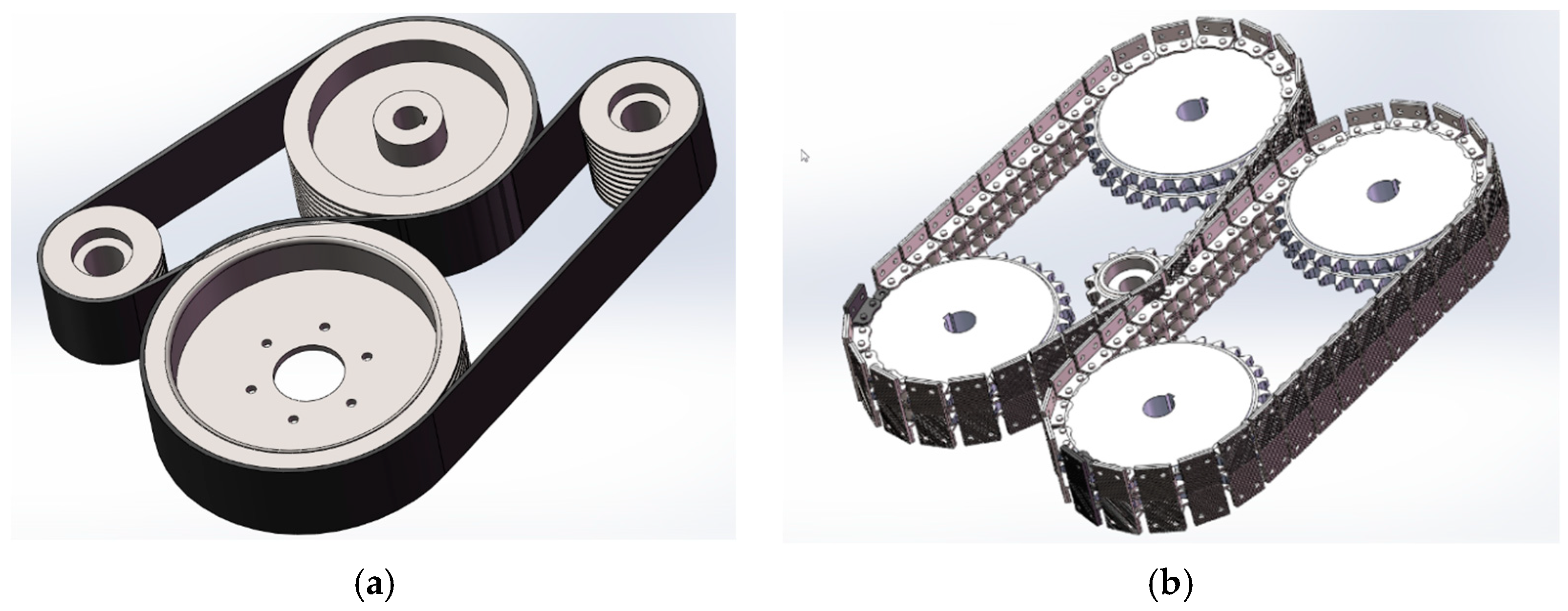
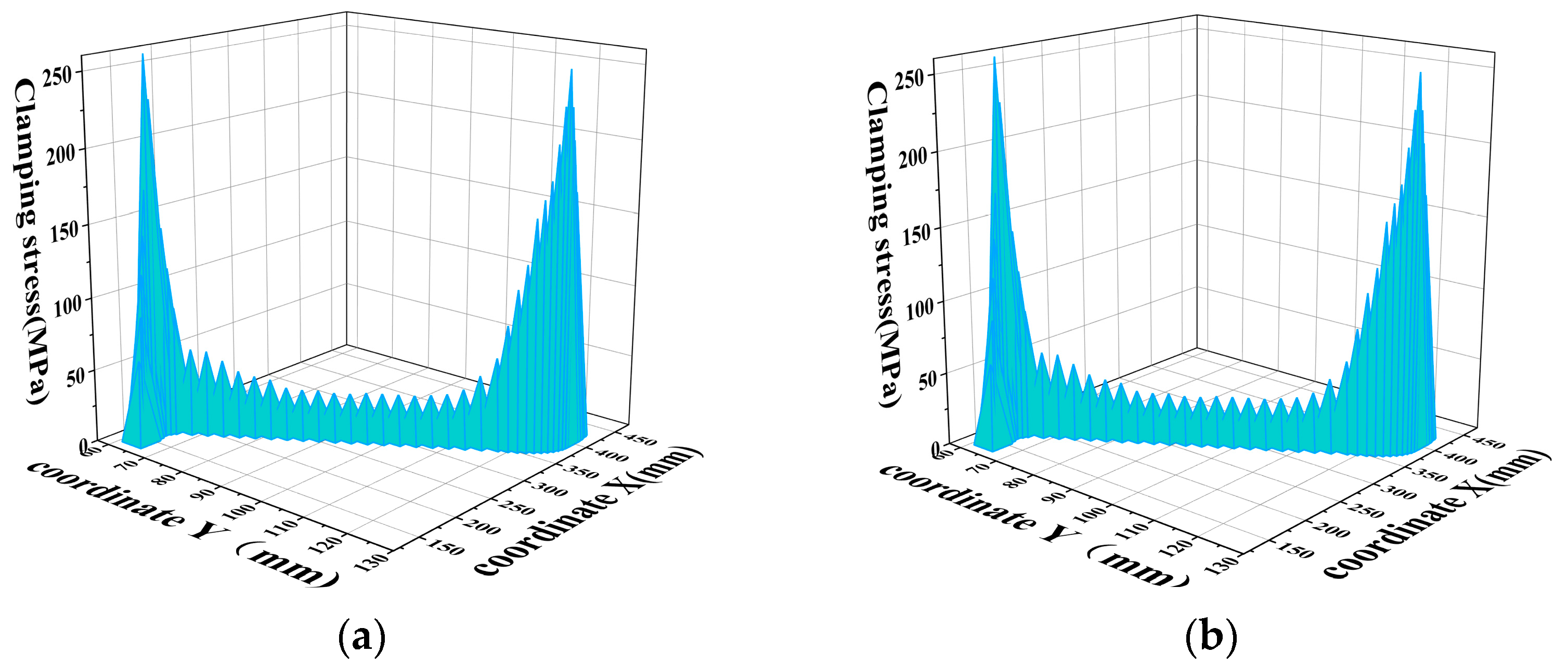
  • In the analogical analysis of the cotton straw harvester based on the clamping path in the same environmental state, in the two-dimensional pulling path analysis, the chain-clamping side can be simplified as a straight line, the curvature is regarded as 0, and the curvature of the clamping side of the belt C1max = 8. The curvature of the belt-clamping side is greater than the curvature of the chain-clamping side so as to obtain a more complete path of the clamping force. According to the Workbench mechanical simulation of the clamping force of the two mechanisms, in the two lifting paths, the clamping force of the chain-clamping side increases dramatically at the feeding point, and the maximum clamping stress can reach 305 MPa. In terms of the slope change, compared with the maximum slope change of the two clamping structures, the value of the slope change of the chain clamping is more than that of the belt-clamping side by 6.56%, which is close to each other. In the analysis of the length of the working path, the maximum gripping path of the belt-clamping side is more than that of the belt-clamping side by 19.45%. In summary, the S-shaped extraction path of the belt-clamp side is longer than the linear path of the chain clamp, resulting in a higher extraction rate and lower straw breakage rate. Therefore, the clamped structure is more advantageous than the chained structure.
  • According to the field test verification, the lowest pull-off rate of the belt-clamping side was 7.14%, and the highest pull-off rate was 14.86%. The lowest pull-off rate was 82.34%, and the highest pull-off rate was 90.13%. The lowest pull-off rate of the chain-clamping side was 18.54%, and the highest pull-off rate was 29.54%. The lowest pull-off rate was 62.56%, and the highest pull-off rate was 71.36%. The average difference between the two organizations is 13.31% in the pull-off rate and 19.32% in the pull-off rate. The difference between the two leakage rates is 6.01%, so the main reason for the lower pull-out rate of the chain-clamp side than the belt-clamp side is the higher pull-out rate, and the secondary reason is the high leakage rate.
In summary, the clamping side of the pulling mechanism trajectory has a greater curvature. After determining that the deformation effect of flexible clamping on the cotton straw is smaller, flexible clamping compared to rigid clamping has a smoother clamping force change curve, the clamping damage rate is lower, and cotton root–soil coupling to reduce the resistance of cotton straw pulling and clamping trajectory of the whole path of the average clamping force is higher. This can be produced by a sustained clamping force of the cotton straw to reduce the rate of pulling and the pulling rate of the leakage of the cotton straw so as to increase the rate of pulling of the net.

Author Contributions

Conceptualization, Y.W. and J.Z.; methodology, Y.W., J.Z. and Y.H.; software, Y.W. and J.Z.; validation, Y.W., J.Z., Z.L. and Z.W.; formal analysis, Y.W. and J.Z.; investigation, Y.W., Y.H., Y.H. and J.L.; data curation, Y.W., J.Z. and Y.H.; writing—original draft preparation, Y.W., J.Z. and Y.H.; writing—review and editing, Y.H., J.Z. and Y.H.; visualization, Y.W., J.L. and Z.L.; supervision, J.Z.; funding acquisition, J.Z. All authors have read and agreed to the published version of the manuscript.

Funding

This work was financially supported by the National Natural Science Foundation of China (52365038), the National Natural Science Foundation of China (51865058), and the China Agricultural Science and Technology Extension and Service Program (NTFW-2022-17).

Institutional Review Board Statement

Not applicable.

Data Availability Statement

Data are contained within the article.

Acknowledgments

The authors thank the editor and anonymous reviewers for providing helpful suggestions for improving the quality of this manuscript.

Conflicts of Interest

The authors declare no conflicts of interest.

References

  1. Chen, M.; Zhao, W.; Wang, Z.; Zhang, J.; Xie, H.; Han, B. Research status of technology related to cotton stalk extraction. China J. Agric. Chem. 2019, 40, 29–35. (In Chinese) [Google Scholar] [CrossRef]
  2. Pandirwar, A.P.; Khadatkar, A.; Mehta, C.R.; Majumdar, G.; Idapuganti, R.; Mageshwaran, V.; Shirale, A.O. Technological advancement in harvesting of cotton stalks to establish sustainable raw material supply chain for industrial applications: A review. BioEnergy Res. 2023, 16, 741–760. [Google Scholar] [CrossRef]
  3. Dong, S.; Wang, F.; Qiu, Z.; Sun, Y. Design and experiment of self-propelled cotton stalk picking harvester. Trans. Chin. Soc. Agric. Mach. 2010, 41, 99–102. [Google Scholar]
  4. Xie, J.; Wu, S.; Cao, S.; Zhang, Y.; Zhao, W.; Zhou, J. Design and testing of clamping roller type cotton stalk extraction device. Trans. Chin. Soc. Agric. Mach. 2023, 54, 101–111. [Google Scholar] [CrossRef]
  5. Luo, T.; Cheng, C.; Li, F. Inverse solution of redundant robot arm based on glow worm swarm optimization alhorithm of time-varying. Comput. Integr. Manuf. Syst. 2016, 22, 576–582. (In Chinese) [Google Scholar] [CrossRef]
  6. Xu, X.; Li, L.; Ren, B.; Zhu, C. Dynamic Characterization of Spatial Axis Cross-Angle Herringbone Planetary Gear System. J. Mech. Eng. 2023, 59, 141–150. [Google Scholar] [CrossRef]
  7. Cai, J.; Zhang, J.; Ye, T. Design and testing of a gripper belt type cotton stalk harvester. Trans. Chin. Soc. Agric. Eng. 2023, 59, 141–150. [Google Scholar] [CrossRef]
  8. Hou, J.; Li, C.; Lou, W.; Zhou, K.; Li, Y.; Li, T. Design and Test of Floating Clamping Device for Garlic Combine Harvester. Trans. Chin. Soc. Agric. Mach. 2023, 54, 137–145. [Google Scholar] [CrossRef]
  9. Zhang, G.; Li, Y.; Li, Z.; Zhang, Y.; Zhai, K. Measuring system of cotton stalk real-time pull force in the field based on LabVIEW. In Proceedings of the ASABE 2014 Annual International Meeting, Montreal, QC, Canada, 13–16 July 2014. Paper 141912493. [Google Scholar] [CrossRef]
  10. Chen, X. Parameter Calibration of Discrete Element Model for Cotton Rootstalk–Soil Mixture at Harvest Stage in Xinjiang Cotton Field. Agriculture 2023, 13, 1344. [Google Scholar] [CrossRef]
  11. Zhang, B.; Liang, R. Test and Analysis on Friction Characteristics of Major Cotton Stalk Cultivars in Xinjiang. Agriculture 2022, 12, 906. [Google Scholar] [CrossRef]
  12. Yan, G.-L.; Tian, S.-F.; Mu, X.-M.; Cao, C.-M.; Wang, R.-B.; Chen, Z.-K. Influence of ear stripping and stalk harvesting time on main nutrient components of sweet corn stalks. Pratacultural Sci. 2015, 9, 1323. [Google Scholar] [CrossRef]
  13. Pan, Z.G. Research on Cotton Stalk Harvester Based on Double Roller Type. Adv. Mater. Res. 2014, 945–949, 286–289. [Google Scholar] [CrossRef]
  14. Dong, X.; Zhang, Z.; Wang, S.; Shen, Z.; Cheng, X.; Lv, X.; Pu, X. Soil properties, root morphology and physiological responses to cotton stalk biochar addition in two continuous cropping cotton field soils from Xinjiang, China. PeerJ 2022, 10, e12928. (In Chinese) [Google Scholar] [CrossRef]
  15. Baker, K.D.; Hughs, E.; Foulk, J. Cotton Quality as Affected by Changes in Spindle Speed. Appl. Eng. Agric. 2010, 26, 363–369. [Google Scholar] [CrossRef]
  16. Zhou, T.; Tian, B.; Chen, Y.Q.; Shen, Y. Painlevé analysis, auto-Bäcklund transformation and analytic solutions of a (2 + 1)-dimensional generalized Burgers system with the variable coefficients in a fluid. Nonlinear Dyn. 2022, 108, 2417–2428. [Google Scholar] [CrossRef]
  17. Zhang, J.; Rui, Z.; Cai, J. Design and testing of a front-mounted belt clamping and conveying cotton stalk puller. Trans. Chin. Soc. Agric. Mach. 2021, 52, 77–152. [Google Scholar] [CrossRef]
  18. Tang, Z.; Han, Z.; Gan, B.; Bao, C.; Hao, F. Design and testing of a harvesting stand for cotton straw pulling in the wrong row. Trans. Chin. Soc. Agric. Mach. 2010, 41, 80–85. [Google Scholar]
  19. Gorlova, I.; Khalmuradov, T. Experimental technology for harvesting the cotton yield. E3S Web Conf. 2021, 258, 04039. [Google Scholar] [CrossRef]
  20. Zhang, J.; Gao, Z.; Cai, J. Design and test of transverse-axis counter-roller type cotton stalk pulling device. Trans. Chin. Soc. Agric. Eng. 2021, 37, 43–52. [Google Scholar] [CrossRef]
  21. Li, Y.; Cheng, C.; Xu, L. Design and experiment of baler for 4L-4.0 combine harvester of rice and wheat. Trans. Chin. Soc. Agric. Eng. 2016, 32, 29–35, (In Chinese with English abstract). [Google Scholar]
  22. Zhang, B.; Chen, X. Cotton stalk restitution coefficient determination tests based on the binocular high-speed camera technology. Int. J. Agric. Biol. Eng. 2022, 15, 181–189. [Google Scholar] [CrossRef]
  23. Zhang, J.; Zhang, P.; Zhang, H.; Tan, C.; Wan, W.; Wang, Y. Discrete Element Simulation Parameters Calibration for Xinjiang Cotton Straw. Trans. Chin. Soc. Agric. Mach. 2024, 55, 76–84+108, (In Chinese with English abstract). [Google Scholar] [CrossRef]
Figure 1. Cotton straw-harvester structure diagram: (1) hydraulic oil tank; (2) retainer; (3) machine skeleton; (4) JHP3200 hydraulic pump; (5) drive pulley; (6) drive pulley; (7) grain elevator; (8) tensioning pulley; (9) tension beam; (10) input shaft; (11) driven sprocket; (12) tension sprockets; (13) tension sprockets; (14) tension sprockets; (15) BM2-100 hydraulic motor.
Agriculture 14 00950 g001
Figure 2. Three-dimensional modeling of two different pinch roll extraction mechanisms: (a) 3D model with clamping side; (b) 3D modeling of the chain-clamping side.
Agriculture 14 00950 g002
Figure 3. Motion path clamping stress curve: (a) clamping side; (b) chain-clamp side.
Agriculture 14 00950 g003
Figure 4. The 2D coordinate creation with clamping mechanism.
Agriculture 14 00950 g004
Figure 5. Method of determining the position of the feed point.
Agriculture 14 00950 g005
Figure 6. Chain-clamping mechanism coordinate establishment.
Agriculture 14 00950 g006
Figure 7. Cotton straw deformation analysis diagram.
Agriculture 14 00950 g007
Figure 8. Modeling of the rheostat Figure.
Agriculture 14 00950 g008
Figure 9. Force analysis of cotton straw with clamping side.
Agriculture 14 00950 g009
Figure 10. Chain-clamp side cotton stalk force analysis.
Agriculture 14 00950 g010
Figure 11. Deformation of straw via two clamping methods.
Agriculture 14 00950 g011
Figure 12. Equipment field verification test chart.
Agriculture 14 00950 g012
Figure 13. Comparison chart of the point and line test of the two mechanisms: (a) breakthrough rate; (b) net extraction rate.
Agriculture 14 00950 g013
Table 1. Main technical parameters.
ParametersValue
Size of the machine
(mm × mm × mm)
1000 × 1200 × 1360
Working width (mm)880
Driving formTractor rear output with hydraulic pump drive
Hook-up formRear suspension type
Number of lines of work4
Working speed (m/s) 2~4
Clamping pulley diameter
(mm + mm + mm)
120 + 120 + 317 + 250
Clamping sprocket diameter
(mm × Number)
188.5 × 4
Table 2. Test factor code.
Serial NumberConsiderations
Drive Wheel Speed/(r·min−1)
−1250
0300
1350
Table 3. Test methods and results.
Test NumberConsiderationsOrganization NumberBreakthrough Rate
P1/%
Net Extraction Rate
P2/%
(r·min−1)
1250L7.3089.80
27.5289.52
37.1490.13
4T18.6271.24
518.5471.36
619.4370.46
7300L11.2086.15
811.3386.04
911.5185.98
10T24.4366.96
1125.0466.52
1224.8367.25
13350L14.8682.34
1413.5283.62
1513.7883.24
16T28.6263.10
1729.5462.56
1828.9663.46
Table 4. ANOVA test with clamped side.
SSdfMSFp-Value
breakthrough rateintergroup68.878234.439182.678<0.01
within a group1.13160.189
net extraction rateintergroup68.640234.320193.244<0.01
within a group1.06660.178
Table 5. Chain-clamp sideways ANOVA test.
SSdfMSFp-Value
breakthrough rateintergroup157.984278.992249.047<0.01
within a group1.90360.317
net extraction rateintergroup95.549247.775247.495<0.01
within a group1.15860.193
Disclaimer/Publisher’s Note: The statements, opinions and data contained in all publications are solely those of the individual author(s) and contributor(s) and not of MDPI and/or the editor(s). MDPI and/or the editor(s) disclaim responsibility for any injury to people or property resulting from any ideas, methods, instructions or products referred to in the content.

