Article

Design and Test of a Crawler-Type On-Film Precision Cotton Seeding Device on DEM-CFD

1
Institute of Mechanical Equipment, Xinjiang Academy of Agricultural and Reclamation Science, Shihezi 832000, China
2
Key Laboratory of Northwest Agricultural Equipment, Ministry of Agriculture and Rural Affairs, Shihezi 832003, China
*
Author to whom correspondence should be addressed.
Agriculture 2024, 14(6), 962; https://doi.org/10.3390/agriculture14060962
Submission received: 7 May 2024 / Revised: 11 June 2024 / Accepted: 14 June 2024 / Published: 19 June 2024
(This article belongs to the Section Agricultural Technology)

Abstract

:
To solve the limitation of speed in the operation of air-suction cotton precision seeding devices, a new crawler-type precision on-film seeding device was designed using an extended duckbill hole-forming device to produce hole-forming belts and lateral seed collection. Coupling simulation of seeding, and analysis of drag force and movement speed of cotton seeds were conducted on EDEM-CFD. A mechanical model of the operation was established, and the effects of the suction hole diameter, pressure relief block length, and wind pressure on seeding performance were analyzed. Regression models between influencing factors and seeding performance indices were established using response surface methodology. The test data were analyzed using Design Expert 10.0.3. The influence rules for each factor on seeding performance were established. The factors affecting the seeding qualified index exhibited the following order: air pressure > pressure relief block length > suction hole diameter. The optimization goals included defining the maximum value of a qualified single-seed index and the minimum value of the missing index, and the best parameter combination was obtained based on a suction hole diameter of 3.624 mm, pressure relief block length of 63.369 mm, and wind pressure of 3.797 kPa. According to the actual test conditions, the parameters were revised to include a suction hole diameter of 3.6 mm, a relief block length of 63.4 mm, and wind (air) pressure of 3.8 kPa for verification tests. The actual qualified single-seed index is 94.87% ± 0.98 %, the missing index is 1.45% ± 0.32%, and the multiple index is 3.68% ± 0.62%. The difference from the predicted value is within 5%, indicating that this study can provide a reference for the structural design and optimization of crawler-type on-film precision cotton seeding devices.

1. Introduction

Cotton seeds can be squeezed for oils [1], the residues are used feed of livestock, and cotton stalks can be used as raw materials for fruit charcoal production [2,3]. Hence, cotton has many economic benefits. China is a major cotton-growing country. Xinjiang has become the largest production base of Gossypium hirsutum L. in China, owing to its unique geographical and climatic advantages, such as long sunshine hours, sufficient heat, and low rainfall [4]. Mulch sowing can increase temperature, conserve moisture, and inhibit water loss and weed growth [5,6,7], helping crop seedlings withstand low temperatures and drought. Hence, mulching ensures the survival rate of seedlings and allows crops such as cotton and corn to grow at higher latitudes [8].
With the promotion of the mulching planting technology, the degree of Cotton full mechanization has continued to increase. As increasingly fewer laborers are engaged in agricultural production, the per capita cultivated area has increased sharply, and ‘labor shortages’ have become prominent during spring sowing. Farmers urgently need a precision mulching seeder with a short farming time, low field work intensity, and high operating efficiency, so as to relieve ‘seeding pressure’ and seize the farming time. The seed meter is the core unit of the cotton seeding equipment used to achieve precise on-film sowing operations.
According to the cotton planting requirements of Xinjiang Production and Construction Corps, the operating speed of the duckbill-type on-film precision hole seeder commonly used in Xinjiang does not exceed 4 km/h [9,10]. If the machine speed is forcibly increased, the opening time and closing time of the duckbill is shortened. During planting, cotton seeds are easily hit in the middle by the duckbill knife that quickly returns to the position, causing the cotton seeds to jump out of seed holes. Moreover, an increase in the rotational linear speed causes the seeds to be taken out of holes before they have time to leave the duckbill cavity, eventually forming floating seeds. In addition, mulch films are constantly cut, squeezed, and released during hole formation and are prone to changes in position and shape, causing problems such as dislocation, film tearing, and film picking. If the stress time is shorter, the rebound effect is more obvious, causing the film holes to deviate from the holes, thereby leading to dislocation. To solve the limited seeding speed of mulching hole seeders during cotton seeding in Xinjiang, we propose a new crawler-type on-film precision cotton seeding device. Specifically, the duckbill hole-forming device was extended to produce hole-forming belts and prolong the duckbill opening time. These changes ensure the sufficient fall of cotton seeds, stabilize the opening shape of mulch films, and achieve delayed hole formation and seeding, thus increasing the hole-forming speed and achieving high-speed seeding.

2. Structures and Working Principle

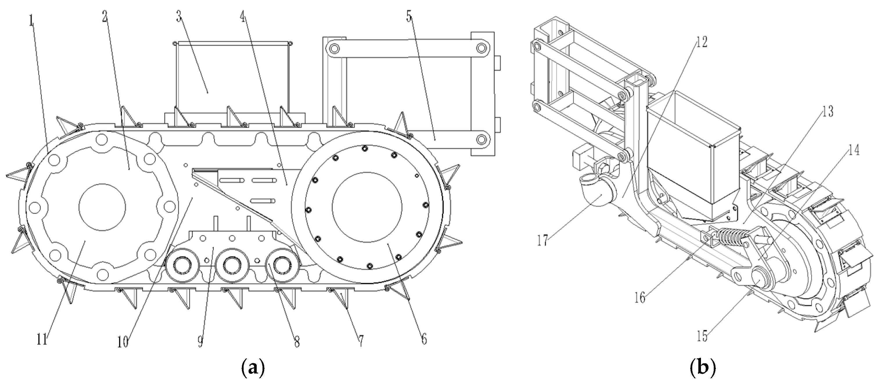
2.1. Overall Structure

The structure of the crawler-type precision on-film cotton seeding device is shown in Figure 1. It mainly consists of a crawler, auxiliary wheels, guiding wheels (seeding wheels), duckbills, a mainboard basal plate, and frame profiling hangers. The overall structure is fixed on a tractor through the slot section of a four-link support rod. The frame profiling hangers support the overall structure and connect the four-link support rod and the mainboard base plate. The auxiliary wheels and guide wheels (seeding wheels) are fixed on the left and right sides of the mainboard base plate, respectively, through connecting shafts. The tension wheels are fixed on the mainboard base plate through the tension wheel support plate. The guide wheel adjustment plate is located between the mainboard base plate and the frame profiling hanger to adjust the left and right spacing between the auxiliary wheel and the guide wheel (seeding wheel). The spring rod of the auxiliary wheel axle seat is fixed on the frame profiling hanger to adjust the relative displacement between the hanger and the mainboard base plate.

2.2. Working Principle

When the crawler-type on-film precision cotton seeding device is used in sowing operations, the tractor provides power to the guide wheel (seeding wheel) assembly to drive the crawler to rotate, and the crawler drives the auxiliary wheels to rotate. The fan continuously provides suction inside the guide wheels (seeding wheels) through the reducing elbow. Under the action of negative pressure suction, the cotton seeds in the seed guide box are suction on the suction holes in the outer shell of the guide wheels (seeding wheels). When the suction seeds are transferred to the seeding area, the silica gel rollers of the pressure relief structure block the seed suction holes on the guide wheels (seeding wheels), isolating the pressure of the suction holes, and the seeds lose their suction force. Under the action of centrifugal force and gravity, the seeds fall into the holes. The seed hole nest is located inside the crawler, and the seeds pass through the seed hole nest and finally fall into the duckbills. The duckbill hole-forming device rotates with the crawler until it makes contact with the ground. The duckbill tears through the mulch and is opened. Under the action of the tension wheels, the crawler and the soil make full contact. The duckbill hole-forming device extends along with the crawler to form a crawler-type hole-forming structure (Figure 2). The common ‘point’ opening is extended to a ‘line’ opening. The opening time of the duckbill is prolonged under the pressure of the crawler and the compaction wheel, providing sufficient time for seeding, achieving delayed hole formation and seeding and ultimately increasing the seeding speed.

3. Design of Key Structures

3.1. Structural Design of the Guide Wheels (Seeding Wheels)

The guide wheels (seeding wheels) structure shown in Figure 3 are fixed on the mainboard base plate through countersunk square-necked bolts and guide shafts. The guide shafts are hollow, and one end is connected to the fan through a reducing elbow to provide a negative pressure environment in the entire shell. The outer sealing gas cover, inner windshield cover, and rubber gasket are sealed shells. The clip spring for holes and the bearing bushing can restrict the axial movement of each component. The outer shell is driven by the crawler to rotate synchronously with the auxiliary wheel assembly. The pressure-relieving silicone trolley wheels are pressed against the inner wall of the shell. When the suction holes in the outer shell of the seeding wheels carry cotton seeds to the pressure-relieving roller wheels, the negative pressure is cut off, so the seeds lose their suction force and fall into the holes under the action of gravity and centrifugal force.
In the structure of the crawler-type cotton on-film precision seeding device, the guide wheels (seeding wheels) are mainly responsible for seed filling, carrying, and dropping. The wheel size determines the size, rotation speed, suction hole number, negative pressure, and energy consumption of the seeding device. The relationship between the displacement of the seeding wheels (Q, holes/s) and the advancing speed of the machine (V, m/s) is expressed as follows:
Q = v g d = v l
where Vg is the linear velocity of the seeding wheels, m/s; l is the row distance, m; and d is the diameter of suction holes, m.
From Equation (1), we obtain the following:
v g = v d l = π v D l Z D = 60 v d π n l Z = π D d
where D is the diameter of the seeding wheels, m; Z is the number of circumferential suction holes, holes; and n is the rotating speed of seeding wheels, r/min.
According to Equation (2), under the premise of certain plant spacing l and machine advancing speed V, when the operating speed is constant, the seeding wheel diameter D is directly proportional to the linear speed Vg and inversely proportional to the number of suction holes Z. A larger diameter of seeding wheels means a larger number of suction holes. In addition, a larger negative pressure is required in the air chamber, and a higher requirement for fan power is noted. When small-diameter seeding wheels are selected, the number of suction holes arranged on the surface of the seeding wheels is less, the speed of the seeding wheels is high, and the negative pressure required in the air chamber is low. However, if the speed is too high, the seed suction effect will be poor, and missed sowing will easily occur. At present, the selected diameter range is generally 140–260 mm worldwide [11,12]. Given the characteristics of cotton seeds, the overall size of the hole seeding structure, operating speed, and fan power, we finally selected the diameter D of guide wheels (seeding wheels) to be 245 mm.

3.1.1. Physical Properties of Cotton Seeds

The suction hole diameter of the seeding device is determined according to the material properties, such as the geometric size of cotton seeds. The surface of the treated cotton seeds is smooth, and the seeds are oval like in shape. Three species of cotton (Xinluzao 53, Xinluzao 61, Jinken 1775) were planted, and 200 seeds were used for each species. The triaxial dimensions (length, width, and thickness) of each seed were measured. The physical dimensions were statistically analyzed (Table 1), and the data were all presented as mean values.

3.1.2. Shape and Size of Suction Holes

The suction hole shape, the difficulties in processing and manufacturing, and the airflow velocity at different types of hole inlets all largely impact the seed suction effect of the seeding device. After comprehensive consideration, the hole type was finally determined to be a straight hole. The suction force P of a suction hole is expressed as follows:
P = π d 2 4 P 0 P 1
where P0 is atmospheric pressure, kPa; P1 is the internal negative pressure of seeding wheels, kPa; and d is the suction hole diameter, mm.
Suction force doesn’t increase. Suction force remains same as the atmospheric pressure and negative pressure are constant. Due to bigger size of holes on the seeding wheel, more seeds will be sucked in resulting in multiple droppings of seeds. When the suction hole diameter decreases, the suction force at the suction hole is weakened, which will exacerbate missed sowing. To improve the single-seed qualified rate and reduce the multiple rate and missing rate, the range of suction hole diameter d is calculated empirically as follows [13]:
0.64 b d 0.66 b
where b is the average width of seeds, mm. The diameter d of the suction hole is selected as 3.0 to 4.0 mm according to the width distribution and processing technology of three types of cotton seeds.

3.1.3. Determination of Suction Hole Number

After the diameter D of the seeding wheel is determined, a larger number of circumferential suction holes Z will lead to a lower linear speed Vg of the seeding wheel and better seed filling performance [14]. Therefore, there shall be as many suction holes as possible on the seeding wheels, but the actual number of suction holes Z shall be determined according to the cotton planting distance of Xinjiang Production and Construction Corps. At present, the plant spacing l of cotton grown in Xinjiang ranges from 9 to 12 cm, so the seeding wheels of the crawler-type cotton on-film hole seeding machine ensures that the plant spacing l is 12 cm. The number of suction holes Z is determined using the following equation:
Z = π D + 2 h l
where h is the height of the duckbill hinge. The number of suction holes of the seeding wheels is finally determined to be Z = 8 using Equation (6). The number of suction holes of the seeding wheels can be adjusted to 10, 12, or 16 as needed, and the crawler of a corresponding size can be replaced.

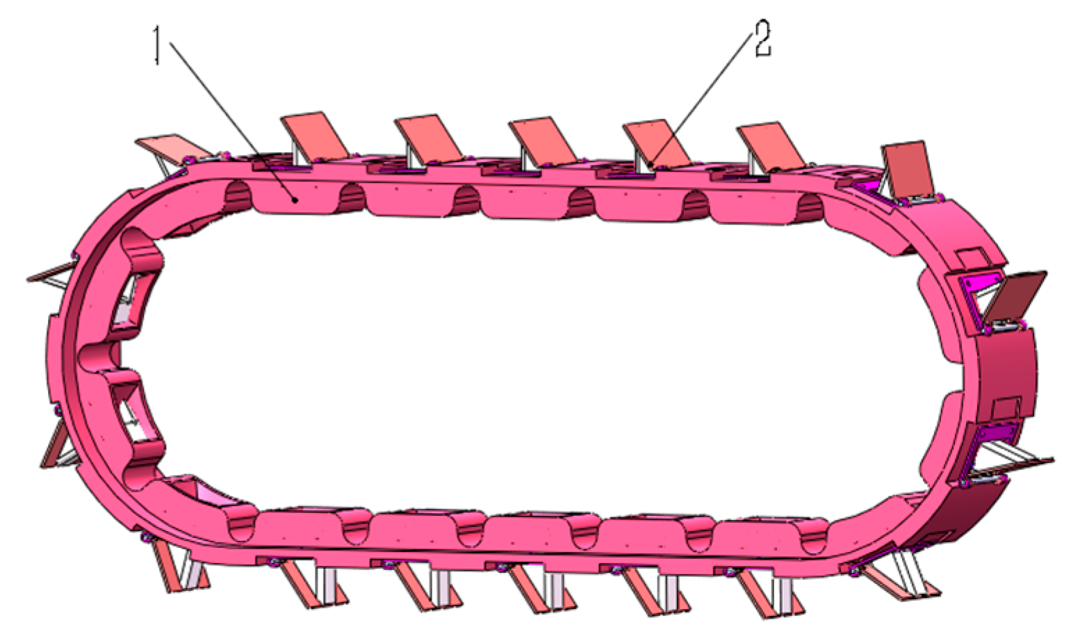
3.2. Design of the Hole-Forming Structure

3.2.1. Design of the Hole-Forming Crawler

The hole-forming structure is responsible for opening holes in the film and guiding the seeding. The hole-forming structure of the crawler-type on-film precision cotton seeding device consists of hole-forming duckbills and a hole-forming crawler. The duckbills are embedded in the crawler. The crawler is composed of crawler blocks, and each block has a seed hole nest. The installation positions of the duckbills correspond to the seed hole nests on the crawler. Specifically, the seed opening of duckbills corresponds to the seed hole nest of the crawler. The duckbill crawler is stretched horizontally, opened from a common ‘point’, and extended to a ‘line’, thereby achieving the effect of delayed hole formation and planting. Moreover, sufficient conditions are provided to ensure that cotton seeds completely fall and to stabilize the opening shape of mulch films. Since the seeding wheels have a diameter D of 245 mm and 16 holes, the crawler length L is expressed as follows:
L = π D + 2 l 0
where l0 is the center distance between the seeding wheels and the auxiliary wheels. Based on the calculation, the crawler length L is 1632 mm, and the crawler width M = 90 mm. The structural diagram is shown in Figure 4.

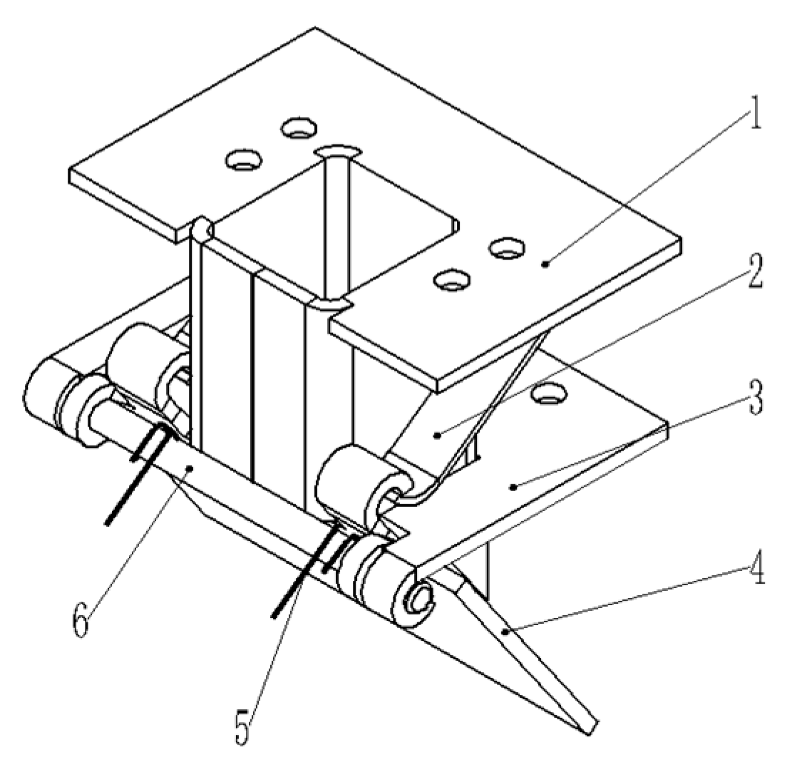
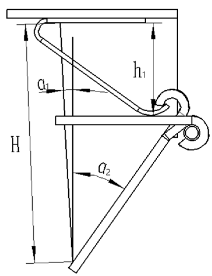
3.2.2. Design of Hole-Forming Duckbills

Duckbills are the core component of the hole-forming device, and the duckbill structure is shown in Figure 5. The duckbill mounting plate is embedded into the crawler, and the spring leaf is fixed between the fixed mouth and the connecting plate. The duckbill with a moving mouth and the fixed mouth duckbill are connected with fixed pins. During the rotation, the fixed mouth duckbill first contacts the ground, inserts into the soil, and pierces the mulch films. Then, the duckbill with the moving mouth contacts the ground and rotates around the fixed pins. The spring leaf is continually compressed by the tension wheels, and the duckbill opens a certain distance to complete the seed dropping procedure. As the duckbill continues to rotate, the movable mouth gradually leaves the ground and closes under the rebound force of the spring leaf.
The duckbill penetration depth h1 directly affects the sowing depth of cotton seeds. Cotton hole-sowing agronomy in Xinjiang requires that the cotton sowing depth is generally between 20 and 30 mm [15]. On this basis, the duckbill length H is expressed as follows:
h max = h 1 cos α 1 k 1
H = h 1 + h
where k1 is the coefficient of variation; α1 is the angle from the connection line between the duckbill’s fixed mouth terminal and rotation center to the fixed mouth lateral wall, °; hmax is the maximum sowing depth of cotton seeds, mm; and h1 is the valid buried soil depth of the fixed mouth duckbills.
According to the preliminary tests, the fixed mouth width l shall surpass the maximum triaxial size of cotton seeds (Table 1) and shall be consistent with the width of the ruptured film hole. After comprehensive consideration, the fixed duckbill width is selected to be 25 mm. The range of the fixed mouth duckbill length H is 50 mm ≤ H ≤ 80 mm. The inclination angle α1 of the fixed mouth affects the soil penetration performance of the hole-forming device, film picking, and amount of soil movement [16]. The initial setting is 10°. Given that the soil surface is uneven and the duckbill generally cannot be completely inserted into the soil, the variation coefficient k1 is added, and k1 is set to be 1.3 [17,18,19]. The hinge height h is related to crawler thickness and seeding wheel radius. It is taken as 20 mm, and hmax is 30 mm. The calculated H is 60.6 mm (here 60 mm is used). The fixed mouth duckbill is schematically shown in Figure 6.
As the inclination angle β1 of the moving mouth increases, the size of the seed holes is enlarged. However, the size is too small, so the cotton seeds are more likely to collide with the inner wall of the duckbill during the process of falling. Thus, β1 is set to be 20°. When the movable mouth rotates to the maximum value, the soil insertion depth of the movable mouth shall be consistent with the depth of the fixed mouth and must meet the following requirements:
h max = h 2 cos β 1 k 1
where h2 is the soil insertion depth of the fixed mouth, mm.
From the previous information, we know k1 = 1.3, hmax = 30 mm, and β1 = 20°, and we determine that h2 = 41.5 mm.
The moving mouth angle β2 affects the distance between the end of the moving mouth and the end of the fixed mouth after the duckbill moves to the lowest point. It is a key parameter that affects the quality of cotton seed dropping and determines the final emergence effect of cotton seeds. If the rolling angle is too small, the duckbill opening distance is too short for the seeds to fall from the duckbill. If the rolling angle is too large, the height difference between the ends of the fixed mouth and the movable mouth increases. Soil easily falls into seed holes from the gap in the duckbill; thus, the falling positions are not fixed. Referring to the existing duckbill sizes and the soil insertion length of the fixed mouth, we set the initial length h2 of the movable mouth to be 40 mm. The maximum duckbill opening value k shall satisfy the following criterion:
k = 1.2 ~ 1.5 α 0 max
where α0max is the maximum triaxial size of cotton seeds, mm.
β 2 = 2 arcsin k 2 h 2
After measurement, the maximum triaxial size of cotton seeds is 9.09 mm, the range of k is 10.9–13.64 mm, and the corresponding duckbill rotation angle is 27.3–34.3°. The schematic diagram of the moving mouth rotation is shown in Figure 7.

3.3. Design of a Seed-Clearing Device

During sowing operations, when the suction holes on the shell of the seeding wheels pass through the seed-filling area to absorb cotton seeds, one hole may absorb multiple cotton seeds. Herein, a scraper-type seed-clearing device was designed and used to remove excessive cotton seeds from suction holes. As shown in Figure 8, two 1 mm-thick silica gel sheets were used to make a smooth arc-shaped seed-clearing sheet. The left and right scrapers are intersected and hinged on the seed guide box, and the distance between the two scrapers is about 1.5 times the average grain distance of cotton seeds. The length of the scraper blade shall meet the requirements that the left and right scrapers can clear seeds at one time. After comprehensive considerations, the length of the seed clearing blade was set to be 45 mm, which is coaxial with the seeding wheel.

3.4. Design of Pressure Relief Structure

The pressure relief structure consists of a bracket, pressure relief blocks (silica gel rollers), bushing, and bearings. As shown in Figure 9, the upper end of the bracket is installed on the guide shaft (hollow shaft), and the lower end is installed with a roller and pressure relief blocks (silica gel rollers). The bracket presses the silicone rollers tightly so that they closely fit the inner walls of the guide wheels (seeding wheels), blocking the seed suction holes and relieving pressure. The pressure relief rollers are installed in the chute of the bracket. The chute has four clamping positions. Adjusting rollers are installed in the four clamping positions so that the silicone rollers are subjected to different extrusion forces, resulting in different amounts of deformation, or namely different sizes of pressure relief blocks. A negative pressure fan is connected to the reducing elbow. The reducing elbow is connected to the guide shaft (hollow shaft) to provide a negative pressure environment in the cavities of the seeding wheels. The seeds adsorbed to seed suction holes pass through the seed-clearing device as the seeding wheels rotate. The seed-clearing device removes excessive seeds, and the remaining seeds are brought to the unloading area as the seeding wheels rotate. At the same time, the pressure relief blocks (silica gel rollers) are close to the inner walls of the seeding wheels and rotate accordingly, blocking the negative pressure in the chamber of the seeding wheels. The cotton seeds fall into the seed holes under the action of gravity and centrifugal force. Thus, seeding is completed.

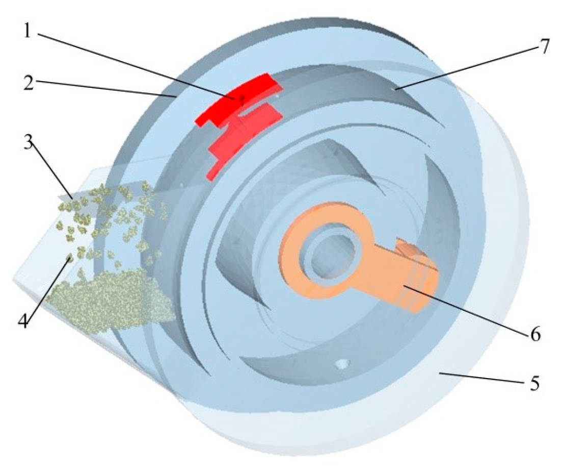
4. Simulation Analysis
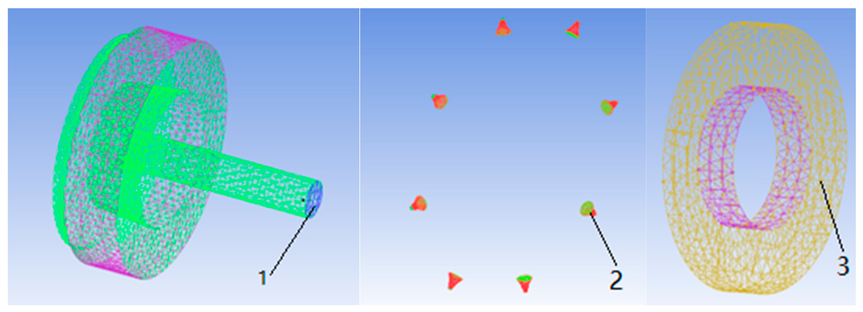
When the crawler-type on-film hole seeder is operating, the cotton seeds exist as grains in the seed guide box. The seeding is affected by airflow and gravity. Therefore, the environment involving the cotton seeds is very complex [20]. CFD and EDEM simulations alone cannot accurately simulate the force and movement of cotton seeds under such complex environment inside the seeding device. Thus, the DEM-CFD gas–solid coupling method is used for analysis.

4.1. Modeling

The cotton seed model was established using SolidWorks. During gas–solid two-way coupling, the simulated grain volume was required to be smaller than the minimum volume of the flow field grid [21], so multiple spherical grains with a volume smaller than the flow field grid were used to fill the cotton seed model. Then, the Bonding V2 key was used to bond all the filled balls together to form a simulation model of cotton seeds [22,23,24,25]. The model filled with small grains bonded by Bonding V2 bond is shown in Figure 10.
A simplified model of the seeding device is shown in Figure 11. The suction hole diameter was small. Thus, to completely retain the suction hole characteristics and ensure the accuracy of the simulation results, the device was first imported into Workbench to generate meshes, saved in the format of stl, and then imported into EDEM to generate grains. ICEM-CFD was used to divide meshes and define the fluid inlet, fluid outlet, suction-hole interface, and wall. The saved mesh file was imported into Fluent. The 8 suction holes were set as sliding meshes, the suction hole part was set as a moving area, and the other areas were set as static areas (Figure 12).

4.2. Determination of Simulation Parameters

During DEM-CFD coupling simulation, the seeding speed in the EDEM and the suction hole speed in the matching fluid area in Fluent were set to be the same. The operating speed of the crawler-type seeding device was 4.5 km/h, which was converted into a rotation speed of 60.88 r/min. The number of grains generated by the grain factory was 598. The seeding device was entirely made of aluminum, and the relevant parameters are shown in Table 2.
Time step was set to be 5 × 10⁻⁶ s in the EDEM and 50 to 100 times that of EDEM in Fluent. The time step in Fluent was 5 × 10⁻⁴ s, and the number of steps was 2000. Namely, the simulation time was 1 s, and max iterations/time step was 1. Each time step can be iterated up to 1 time; data were saved every 0.02 s.

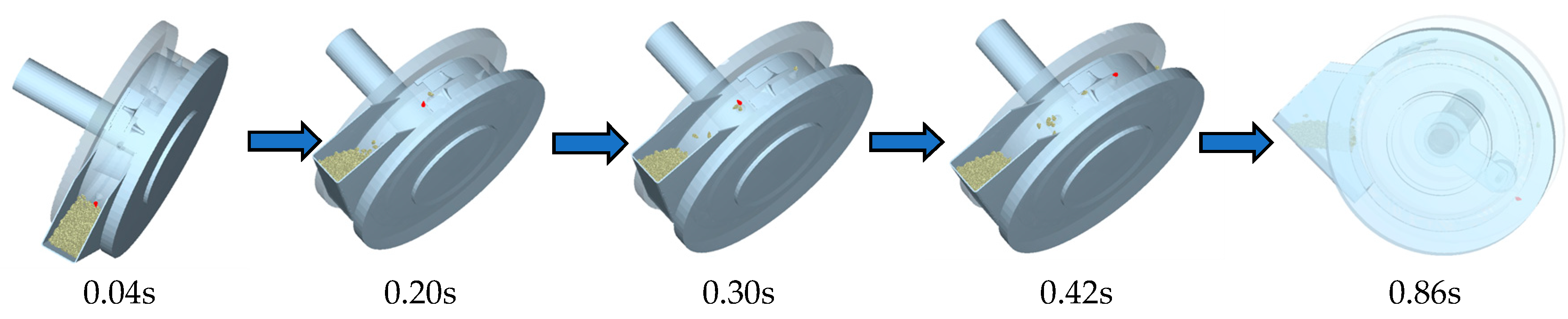
4.3. Results and Analysis

Figure 13 shows the cotton seed stress condition and movement speed as well as the cotton seed Bonding V2 model with a better label adsorption effect, and the Figure 14 is the emporal diagram of seed suction state. The drag force on the cotton seed was the sum of the drag forces on each small grain from the Bonding V2 model, and the movement speed of the cotton seed was the average speed of each grain from the Bonding V2 model.
From 0 to 0.04 s, due to the effect of air flow around the suction hole, the cotton seeds changed from a static state to a moving state around the suction hole, so the drag force on the seeds increased sharply (Figure 13a). From 0.04 to 0.20 s, the cotton seeds were adsorbed unstably in the early stage and broke away from the suction hole after hitting the seed-clearing device, so the drag force fluctuated greatly until it suddenly dropped to 0. From 0.20 to 0.30 s, when the cotton seeds fell back into the seed box, they were affected by the airflow around the next suction hole and were adsorbed again, so the drag force on the cotton seeds rose extremely quickly. From 0.30 to 0.42 s, when the cotton seeds were moving with the seeding device, they interfered with the seed-clearing device and lingered at the suction hole, so the drag force fluctuated. From 0.42 to 0.86 s, the cotton seeds entered the pressure relief zone after experiencing the adsorption stabilization stage. The pressure relief roller isolated the air flow, and the drag force was maximized, slightly fluctuated and then dropped to 0. From 0.86 to 1.00 s, the cotton seeds completely entered the pressure relief zone, and the drag force disappeared.
From 0 to 0.04 s, due to the effect of airflow, the cotton seeds quickly moved from the static state in the seed box toward the suction hole, resulting in a sharp increase in the speed of the cotton seeds (Figure 13b). From 0.04 to 0.20 s, because the cotton seeds were just adsorbed, there were multiple seeds around the suction hole at the same time. With the rotation of the seeding device, the position of the cotton seeds continually changed, resulting in unstable air pressure and large speed fluctuations. When the seeds hit the seed clearing device, the speed dropped sharply. From 0.20 to 0.30 s, when the cotton seeds scraped off by the seed-clearing device fell back into the seed box, they were affected by the airflow of the next suction hole and quickly moved toward the hole until reaching the adsorption state, and the speed increased. From 0.30 to 0.42 s, the adsorbed cotton seeds went through the seed-clearing area again. Due to the interference with the seed-clearing device, the speed fluctuated. From 0.42 to 0.86 s, after stable adsorption, the cotton seeds rotated together with the seeding device, and the speed was the linear speed of the suction hole, showing a horizontal trend. From 0.86 to 1.00 s, when the cotton seeds passed through the pressure relief roller, the airflow in the suction hole disappeared, and the cotton seeds fell freely under the action of gravity until falling outside the simulation area.
Simulation analysis indicates that this design can be used for complete precision sowing operations on cotton films, and the solution is feasible.

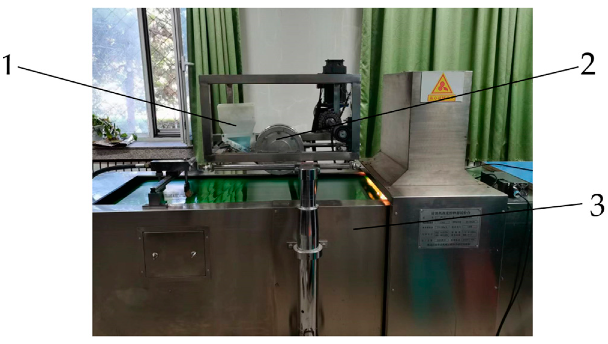
5. Bench Test and Analysis

5.1. Test Materials

The test was conducted on a JPS-12 seeding device performance testing bench. The testing bench is shown in Figure 15. Cotton seeds were selected from Xinluzao 53, Xinluzao 61, and Jinken 1775. The cotton seeds were manually selected and had no damage or impurities. The seed moisture content was 18.3%. Other instruments included a JPS-12 seeding device performance testing bench, a C9002U brushless DC fan, a SUP-Y910 digital pressure gauge, a PH-200LC speed measuring instrument, and a high-speed camera.
As reported [26], the seed data of 250 holes discharged from each group of test seeding devices on the oil belt in the stable working state were collected and analyzed. The tests were repeated three times. The seeding performance indices, including the qualified single-seed index, missing index, and multiple index, were computed as follows:
Y 1 = n 1 250 × 100 % Y 2 = n 2 250 × 100 % Y 3 = n 3 250 × 100 %
where Y1 is the qualified single-seed index; Y2 is the missing index; Y3 is the multiple index; n1 is the hole number with 1 seed; n2 is the hole number; and n3 is the hole number with 2 or more seeds.

5.2. Test Design

Research and theoretical analysis related to seeding meters were comprehensively considered on basis of the Box-Behnken experimental design principle. Combined with pre-test results, the main factors and horizontal ranges that affect the seeding performance of the crawler-type cotton on-film hole seeder are suction hole diameter A, 3.0–4.0 mm; pressure relief block length B, 28–70 mm; wind pressure C, 3.0–4.0 kPa. According to the geometric size of the test cotton seeds (Table 1), the suction hole diameter was 3.0~4.0 mm, and the length of the pressure relief block was 28~70 mm. The negative pressure suction test was carried out according to a reported method [14]. The suction effect was better when the air pressure was within 3.0~4.0 kPa, and these values were chosen as the tested air pressure.
The cotton plant spacing was set as 10 cm. The suction hole diameter A, pressure relief block length B, and wind pressure C were taken as factors, and three horizontal marks were −1, 0, and 1. The response surface software Design Expert 10.0.3 was used to perform factor horizontal design. The levels of the test factors are listed in Table 3, and the response indicators are the qualified index Y1, missing index Y2, and multiple index Y3. Specifically, 17 tests were conducted, and Design Expert 10.0.3 was used to conduct analysis of variance (ANOVA) of the test results and order analysis of the impact of test factors on test indices [27]. The test design and results are shown in Table 4.

5.3. Results and Analysis

5.3.1. Response Surface Methodology (RSM) Design and Results

Table 4 lists the RSM design and results. Let the suction hole diameter, pressure relief block length, and the wind pressure be A, B, and C, respectively. Multiple regression fitting was performed using the qualified single-seed index, missing index, and multiple index as response values, and the following quadratic polynomial regression model was obtained:
Y1 = 94.82 − 0.5A + 0.64B + 0.97C − 0.01AB + 0.26AC + 0.24BC − 0.61A2 − 0.51B2 − 1.8C2
Y2 = 1.47 − 0.055A − 0.095B − 0.18C − 0.0075AB − 0.047AC − 0.038BC − 0.00525A2 + 0.095B2 + 0.075C2
Y3 = 3.71 + 0.5563A − 0.5425B − 0.7912C + 0.0175AB − 0.21AC − 0.2025BC + 0.6185A2 + 0.416B2 + 1.72C2

5.3.2. ANOVA with Regression Models

The ANOVA regression model and significance results are shown in Table 5, Table 6 and Table 7.
The regression model of the qualified single-seed index yielded the following results: p < 0.001 (very significant), lack of fit p = 0.1374 > 0.05 (not significant), regression coefficient R2 = 0.9923, and adjusted R2 = 0.9823 (>0.8000) (Table 5), indicating that 98.23% of the data can be explained by this model. After analysis of the test data, the linear factors suction hole diameter A, pressure relief block length B, and air pressure C all very significantly impact the qualified single-seed index (p < 0.01). The order of the effect of each factor is as follows: air pressure C > length of pressure relief block B > suction hole diameter A. The quadratic terms AC and BC significantly affect the qualified single-seed index (p < 0.05), while AB has no significant impact (p > 0.05). The significant order of the quadratic terms on the qualified single-seed index is AC > BC > AB.
The missing index model exhibits the following values: p < 0.001 (very significant), lack of fit p = 0.2542 > 0.05 (not significant), regression coefficient R2 = 0.9859, and adjusted R2 = 0.9677 (>0.8000) (Table 6), indicating that 96.77% of the data can be explained by this model. The influencing order of the factors is air pressure C > pressure relief block length B > suction hole diameter A. The quadratic term interaction AC and BC have a significant affect on the missing index (p < 0.05), but AB has no significant impact (p > 0.05). The order of influence is AC > BC > AB.
The multiple index regression model yielded the following results: p < 0.001 (very significant), lack of fit p = 0.1431 < 0.05 (not significant), regression coefficient R2 = 0.9932, and adjusted R2 = 0.9845 (>0.8000) (Table 7), suggesting that 98.45% of the data can be explained by this model. The effect order of the factors is air pressure C > suction hole diameter A> pressure relief block length B. The quadratic terms AC and BC significantly affect the missing index (p < 0.05), but AB has no significant impact (p > 0.05). The order of influence is AC > BC > AB.

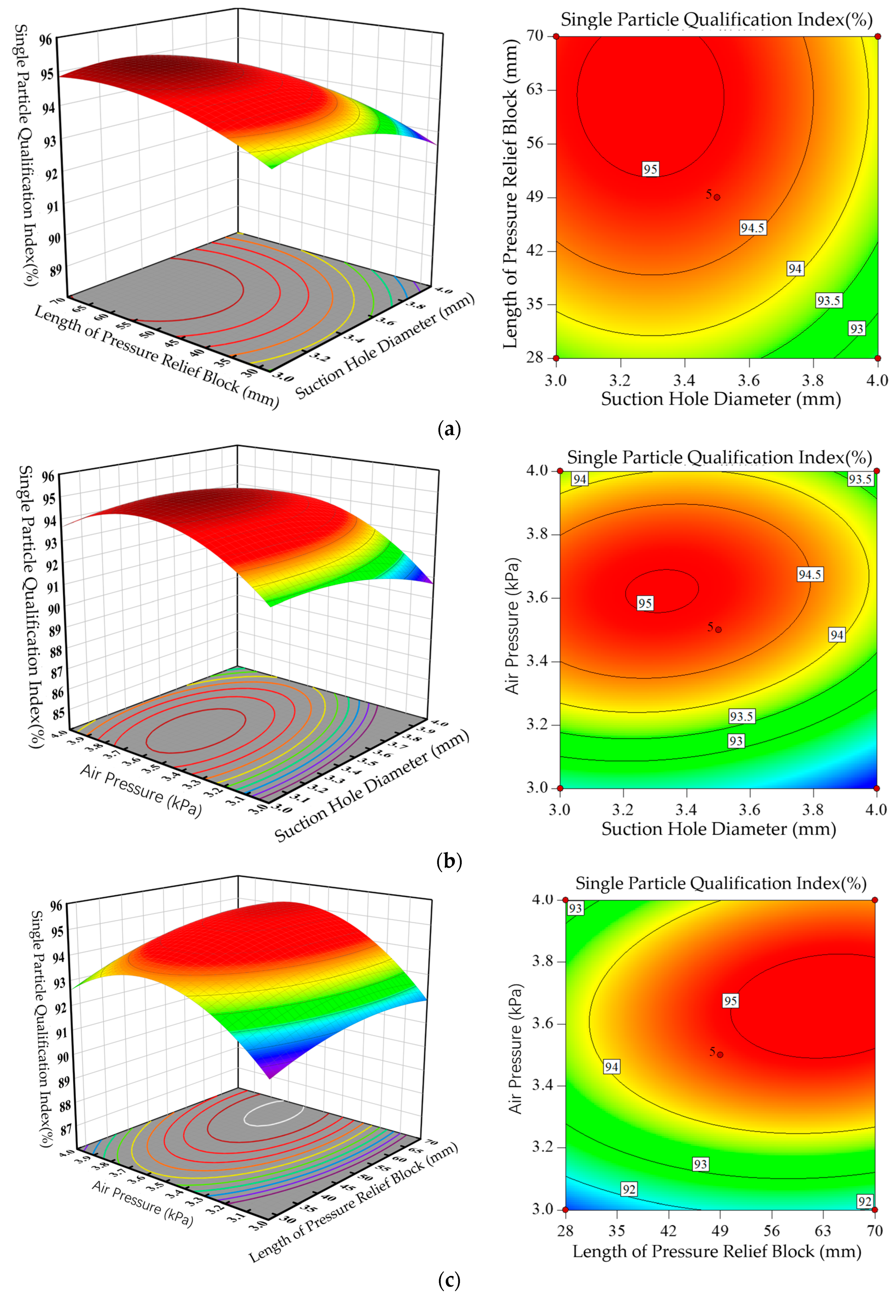
5.3.3. Interactions of Different Factors

According to the regression equations, the data were processed, and the effects of suction hole diameter, pressure relief block length, and wind pressure on the qualified single-seed index were analyzed with Design expert 10.0.3. The slope steepness of the RSM curve corresponds to the influence degree of the two factors on the response value. A steeper slope means the interaction between the two factors is more obvious. The effects of suction hole diameter (A), pressure relief block length (B), and wind pressure (C) on the qualified single-seed index are shown in Figure 16.
The interactive effect between the suction hole diameter and pressure relief block length on the qualified single-seed index is shown in Figure 16a. On the AB interactive surface, the changing slope of the qualified single-seed index gradually decreases as the suction hole diameter increases and slowly rises as the pressure relief block length increases. Suction force remains the same as the atmospheric pressure and negative pressure are constant. With an increase in the suction hole diameter and the subsequent increase in the hole size produced by the seeding wheel, more seeds will be sucked in, resulting in multiple seed being dropped. When the interaction between these two factors is considered exclusively, the qualified single-seed index is larger when the suction hole diameter is 3.0–3.4 mm and the pressure relief block length is 56–70 mm.
The interactive effect between suction hole diameter and wind pressure on the qualified single-seed index is shown in Figure 16b. On the AC interactive surface, the changing slope of the qualified single-seed index first rises and then decreases as the air pressure increases. The seed suction rate increases with greater air pressure, and the single-seed qualified index increases. After the air pressure exceeds the optimal value, the suction seeds may not fall at the falling stage, resulting in missed sowing and a smaller single grain qualified index. At low air pressure, the single-seed qualified index first increases and then decreases as the suction hole diameter increases. Some of the suction seeds fell before they reached the planting area, resulting in a slow increase in the leakage rate. Thus, the qualified single-seed index gradually decreases as the suction hole diameter increases. At high air pressure, the qualified single-seed index first increases and then decreases as the suction hole diameter increases. Here, seeds are completely adsorbed. As the diameter of the suction hole increases, more seeds will be sucked, and the air pressure continues to increase. Some seeds will not fall, resulting in missing seeds. Thus, the qualified index first increases and then decreases as the suction hole diameter increases. A significant interaction occurs between suction hole diameter and wind pressure. When the interaction between the two factors is considered exclusively, the qualified single-seed index is larger when the suction hole diameter is 3.0–3.4 mm and the wind pressure is 3.4–3.8 kPa.
The interactive influence between the pressure relief block length and wind pressure on the single-seed qualified index is shown in Figure 16c. On the BC interactive surface, as the air pressure increases, the single-seed qualified index first increases and then decreases. The qualified single-seed index increases slowly as the pressure relief block length increases. The qualified single-seed index increases slowly as the pressure relief block length increases. When the length of the pressure relief block is a large value, the single grain qualification index does not change much. When the air pressure varies, the changing amplitude of the qualified single-seed index differs as the pressure relief block length increases. This finding suggests that there is a significant interaction between air pressure and pressure relief block length. When only the interaction between these two factors is considered, the qualified single-seed index is greater when the pressure relief block length is 56–70 mm and wind pressure is 3.4–3.8 kPa.
In summary, the interaction between factors significantly impacts the seeding device, so it is necessary to optimize the three factors, achieve the best matching among the three factors, and ultimately improve the qualified index.

6. Parameter Optimization and Experimental Verification

According to the operational performance index requirements in Technical Conditions for Single-Seed (Precision) Seeders (JB/T10293-2013) [28], the optimization target is the qualified single-seed index. Combined with the boundary conditions of each factor, a mathematical model is established and optimized based on its objective functions and constraints as follows:
F max = Y 1 Y 2 Y 3
s . t . Y 1 80.0 % Y 2 8.0 % Y 3 15.0 % 3.0   mm A 4.0   mm 28   mm B 70   mm 3.0   kPa C 4.0   kPa
According to the regression equations, the maximum qualified single-seed index and the minimum missing index are the optimization goals, implying that Fmax is the final optimization goal. The optimization module of Design Expert 10.0.3 is used to constrain the goals and obtain the optimal solution. The optimal conditions are predicted as follows: suction hole diameter of 3.624 mm, pressure relief block length of 63.369 mm, and air pressure at 3.797 kPa. The actual test conditions are revised as follows: suction hole diameter of 3.6 mm, pressure relief block length of 63.4 mm, and air pressure of 3.8 kPa. Under these optimal conditions, after three parallel tests, the actual qualified index is 94.87% ± 0.98%, the missing index is 1.45% ± 0.32%, and the multiple index is 3.68% ± 0.62%. These values are consistent with the predicted values with errors within 5% (single-seed qualified index of 94.936%, missing index of 1.329%, and multiple index of 3.2%). The good experimental performance between the predicted values and the testing values is confirmed, indicating that the structural parameters optimized using RSM are acceptable.

7. Conclusions

(1)
A new crawler-type on-film precision seeding device is designed by extending the duckbill hole-forming device to form hole-forming belts and lateral seed taking. The structure and composition of the hole-forming device are introduced. The working principle determines the structural parameters of the key components of the structure. DEM-CFD gas–solid coupling simulation is used to simulate the drag force and movement speed parameters of cotton seeds during seeding. After the simulation, a response surface test is conducted to establish mechanical models of the operation process and analyze the effects of suction hole diameter, pressure relief block length, and air pressure on the seeding performance.
(2)
An orthogonal combination test is designed, and the RSM software Design Expert 10.0.3 is used to analyze the impact of test factors on the response index. The optimal working parameter combination of the crawler-type on-film cotton hole seeder include the following: suction hole diameter of 3.6 mm, pressure relief block length of 63.4 mm, and air pressure of 3.8 kPa. At this time, the performance indicators of the crawler-type cotton on-film hole seeder are a qualified single-seed index of 94.936%, missing index of 1.329%, and multiple index of 3.2%.

Author Contributions

Conceptualization, H.Z., D.H. and C.J.; methodology, H.Z.; software, H.Z. and D.H.; validation, H.Z., C.J. and F.P.; formal analysis, H.Z. and J.L.; investigation, H.Z; resources, H.Z. and C.J.; data curation, H.Z. and F.P.; writing—original draft preparation, H.Z.; writing—review and editing, H.Z. and D.H.; visualization, H.Z.; supervision, C.J.; project administration, H.Z., D.H. and C.J.; funding acquisition, D.H. and C.J. All authors have read and agreed to the published version of the manuscript.

Funding

This research was funded by the National Natural Science Foundation of China (NSFC) (No. 32101634), the Xinjiang Academy of Agricultural and Reclamation Science Research Project (No. 2022YJ001), the grain and cotton production high-end agricultural machinery and equipment innovation team, and the Young Science and Technology Top Talent Program of Tianshan Talent Training Program in Xinjiang Province (No. 2022TSYCCX0123).

Institutional Review Board Statement

Not applicable.

Data Availability Statement

Data are contained within the article.

Conflicts of Interest

The authors declare no conflicts of interest.

References

  1. Wu, L.F. Coupling Effect of Water and Fertilizer under Fertingation and Simulation Growth of Cotton in Xinjiang. Ph.D. Thesis, Northwest A&F University, Xi’an, China, 2015. [Google Scholar]
  2. Zhang, J.X.; Jiang, Y.X.; Liu, C.; Wang, X.N.; Cheng, F. Implementation status of cotton’s whole course mechaniztion in Xinjiang. Chin. Agric. Mech. 2012, 3, 33–35. [Google Scholar]
  3. Zhang, J.X.; Liu, A.P.; Li, H.; Wang, Y.; Liu, X.; YeErBoLati, T.M. Development of microwave pyrolysis equipment for cotton stalk carbon. Trans. Chin. Soc. Agric. Eng. 2020, 36, 219–225, (In Chinese with English abstract). [Google Scholar]
  4. Wang, X.J. Impact and Adaptation of Climate Change on Cotton Phenology, Yield and Fiber Quality in Xinjiang. Ph.D. Thesis, China Agricultural University, Beijing, China, 2015. [Google Scholar]
  5. Zhou, L.F.; Zhao, W.Z.; Yang, R.; Feng, H. Soil temperature modeling in topsoil with plastic film mulching and low spring temperatures. Arch. Agron. Soil Sci. 2020, 66, 1936–1947. [Google Scholar] [CrossRef]
  6. Shen, Q.X.; Ding, R.S.; Du, T.S.; Tong, L.; Li, S. Water Use Effectiveness Is Enhanced Using Film Mulch Through Increasing Transpiration and Decreasing Evapotranspiration. Water 2019, 11, 1153. [Google Scholar] [CrossRef]
  7. Wen, H.J.; Niu, Q.; Ji, C. Current status of and annalysis on the mechanical technology of plastic film. J. China Agric. Univ. 2017, 22, 145–153. [Google Scholar]
  8. Zhang, D.X. The problem of agricultural plastic film recycling. J. China Agric. Univ. 1998, 3, 103–106. [Google Scholar]
  9. Li, M.; Wang, W.B.; Du, S.; Guo, S.; Li, J. Experiment study on adsorption accuracy of air-suction cutton dibbler. J. Chin. Agric. Mech. 2016, 37, 10–13. [Google Scholar] [CrossRef]
  10. DB65/T2110-2019; Technical Regulations for the Cultivation of Natural Color Cotton. Xinjiang Uygur Autonomous Region Market Supervision and Administration Bureau: Urumqi, China, 2019.
  11. Li, Z.D.; Li, S.S.; Cao, X.Y.; Lei, X.; Liao, Y.; Wei, Y.; Liao, Q. Seeding performance experiment of pneumatic-typed precision centralized metering device. Trans. Chin. Soc. Agric. Eng. 2015, 31, 17–25, (In Chinese with English abstract). [Google Scholar]
  12. Zhang, B.P. Design Principle of Seeding Machine; China Machine Press: Beijing, China, 1982. [Google Scholar]
  13. Chinese Academy of Agricultural Mechanization Sciences, Agricultural Machinery Design Handbook; China Agricultural Science and Technology Press: Beijing, China, 2007; Volume 1, pp. 357–358.
  14. Ni, X.D.; Xu, G.J.; Wang, Q.; Peng, X.; Hu, B. Design and Experiment of Pneumatic Cylinder Array Precision Seed-metering Device for Cotton. Trans. Chin. Soc. Agric. Mach. 2017, 48, 58–67. (In Chinese) [Google Scholar]
  15. DGT100-2023; Filming (Tape) Planter. Ministry of Agriculture and Rural Affairs of the People’s Republic of China: Beijing, China, 2023.
  16. Wang, G. Design and Test of Duckbill Seed-Metering Device for Rice Film Spreading and Hole Sowing Machine. Master’s Thesis, Anhui Agricultural University, Hefei, China, 2023. [Google Scholar]
  17. Teng, Y.J. Design and Study on Key Parts of Type 2BMC-4/8 Precision Hillplanter for Cotton. Master’s Thesis, Shandong University of Technology, Zibo, China, 2015. [Google Scholar]
  18. Zhang, X.J.C.Y.; Shi, Z.L.; Jin, W.; Zhang, H.T.; Fu, H.; Wang, D.J. Design and experiment of double-storage turntable cotton vertical disc hole seeding and metering device. Trans. Chin. Soc. Agric. Mach. 2021, 37, 27–36. [Google Scholar] [CrossRef]
  19. Cai, Y.Q.; Luo, X.; Hu, B.; Mao, Z.B.; Li, J.W.; Guo, M.Y.; Wang, J. Theoretical and experimental analyses of high-speed seed filling in limited gear-shaped side space of cotton precision dibbler. Comput. Electron. Agric. 2022, 200, 107202. [Google Scholar] [CrossRef]
  20. Li, Y.M.; Zhao, Z.; Chen, J.; Xu, L. Element method simulation of seeds motion in vibrated bed of precision vacuum seeder. Trans. Chin. Soc. Agric. Mach. 2009, 40, 56–59. (In Chinese) [Google Scholar]
  21. Shi, S. Design and Experimental Research of the Tic Maize Precision Seed-Metering Device with Combined Holes. Ph.D. Thesis, China Agricultural University, Beijing, China, 2015. (In Chinese). [Google Scholar]
  22. Wang, Y.X.; Liang, Z.J.; Zhang, D.X.; Cui, T.; Shi, S.; Li, K.; Yang, L. Calibration method of contact characteristic parameters for corn seeds based on EDEM. Trans. Chin. Soc. Agric. Mach. 2016, 32, 36–42. (In Chinese) [Google Scholar]
  23. Wang, Z.; Zhao, W.Y.; Shi, L.R.; Sun, B.G.; Sun, W.; Dai, F.; Zhou, G.; Guo, J.H.; Rao, G.; Li, H. Optimization of the motion parameters of a rolling spoon type precision hole planter based on DEM-MBD coupling. J. China Agric. Univ. 2024, 29, 66–77. [Google Scholar] [CrossRef]
  24. Tan, B.F.; Duan, H.B.; Fu, J.; Sun, H.J.; Cai, X.K.; Li, Z.L. Performance simulation of triangle Chain cup-spoon potato seed feeder based on RecurDyn-EDEM coupling. J. Gansu Agric. Univ. 2023, 58, 218–227. [Google Scholar] [CrossRef]
  25. Dong, X.Q.; Su, C.; Zheng, H.N.; Han, R.Q.; Li, Y.L.; Wang, L.P.C.; Song, J.N.; Wang, J.C. Analysis of soil disturbance process by vibrating subsoiling based on DEM-MBD coupling algorithm. Trans. Chin. Soc. Agric. Mach. 2022, 38, 34–43. [Google Scholar] [CrossRef]
  26. GB6973-2005; Testing Methods of Single Seed Drills (Precision Drills). General Administration of Quality Supervision, Inspection and Quarantine of the People’s Republic of China: Beijing, China; Standardization Administration of the People’s Republic of China: Beijing, China, 2005.
  27. Tang, Q.Y.; Feng, G.M. DPS Data Processing System: Experimental Design, Statistical Analysis and Data Mining; Science Press: Beijing, China, 2001. [Google Scholar]
  28. JB/T10293-2013; Technical Conditions of Single Grain (Precision) Seeder. Ministry of Industry and Information Technology: Beijing, China, 2013.
Figure 1. Structure of the crawler-type precision on-film cotton seeding device. (a) Front view. (b) Side view. 1. Hole-forming crawler. 2. Auxiliary wheel. 3. Seed box. 4. Seed guide box. 5. Four-link support frame. 6. Guide wheel (seeding wheel). 7. Hole-forming duckbill. 8. Tension wheel. 9. Tension wheel support plate. 10. Mainboard base plate. 11. Outer disk of auxiliary wheel. 12. Frame profiling hanger. 13. Guide wheel adjustment plate. 14. Auxiliary wheel axle seat. 15. Auxiliary wheel connecting shaft. 16. Auxiliary wheel axle seat spring rod. 17. Reducing elbow.
Agriculture 14 00962 g001
Figure 2. Structural diagram of the crawler-type cotton precision on-film seeding device. 1. Auxiliary wheel. 2. Hole-forming crawler. 3. Hole-forming duckbill. 4. Guide wheel (seeding wheel).
Agriculture 14 00962 g002
Figure 3. Structural drawing of the guide wheel (seeding wheel). 1. Outer shell cover. 2. Pressure relief agencies. 3. Inner windshield cover. 4. Bearing bushing. 5. Outer sealing gas cover of leading axle. 6. Seed-clearing device. 7. Outer shell of seeding wheel. 8. Leading axle. 9. Suction hole. 10. Clip spring for hole. 11. Bearing. 12. Bearing. 13. Clip spring for shaft.
Agriculture 14 00962 g003
Figure 4. Three-dimensional diagram of the hole-forming crawler structure. 1. Hole-forming crawler. 2. Hole-forming duckbill.
Agriculture 14 00962 g004
Figure 5. Structural diagram of the hole-forming duckbill. 1. Fixed mouth duckbill. 2. Spring leaf. 3. Girdle base plate. 4. Duckbill with moving mouth. 5. Release spring. 6. Articulated axle.
Agriculture 14 00962 g005
Figure 6. Structural schematic of the fixed mouth duckbill.
Agriculture 14 00962 g006
Figure 7. Schematic diagram of the moving mouth rotation.
Agriculture 14 00962 g007
Figure 8. Schematic diagram of a seed-clearing device. 1. Seed box. 2. Left scraper. 3. Right scraper. 4. Guide wheel (seeding wheel). 5. Seed guide box.
Agriculture 14 00962 g008
Figure 9. Structural diagram of the pressure relief device. 1. Bracket. 2. Pressure relief block (silica gel roller). 3. Bearing. 4. Bushing. 5. Roller shaft. 6. Chute.
Agriculture 14 00962 g009
Figure 10. Cotton seed simulation model. (a) Object pictures. (b) Three-dimensional model. (c) Bonded grains model.
Agriculture 14 00962 g010
Figure 11. Schematic diagram of simplified model in simulation. 1. Seed-clearing device. 2. Negative pressure chamber. 3. Grain factory. 4. Cotton seed grains. 5. Sealed shell. 6. Air shut-off structure. 7. Suction hole.
Agriculture 14 00962 g011
Figure 12. Schematic diagram of the mesh division and relevant settings. 1. Inlet (internal flow field). 2. Suction-hole (moving area). 3. Outlet (external flow field).
Agriculture 14 00962 g012
Figure 13. Stress and movement speed of cotton seeds. (a) Drag force on cotton seed. (b) Movement status of cotton seed.
Agriculture 14 00962 g013
Figure 14. Emporal diagram of seed suction state.
Agriculture 14 00962 g014
Figure 15. Experimental table of the crawler-type precision on-film seeding device. 1. Seed box. 2. The guide wheels (seeding wheels). 3. JPS-12 seeding device performance testing bench.
Agriculture 14 00962 g015
Figure 16. RSM curve and contour line of the interaction of various factors on the qualified single-seed index. (a) RSM curve and contour line of the interaction of the suction hole diameter and pressure relief block length on the qualified single-seed index. (b) RSM curve and contour line of the interaction of the suction hole diameter and air pressure on the qualified single-seed index. (c) RSM curve and contour line of the interaction of the pressure relief block length and air pressure on the qualified single-seed index.
Agriculture 14 00962 g016
Table 1. Maximum size of the cotton seed triaxial measurement plan.
ParameterXinluzao 53Xinluzao 61Jinken 1775
Length (mm)8.788.499.09
Width (mm)4.684.714.77
Thickness (mm)4.24.43.89
Table 2. Simulation of required physical and mechanical parameters.
ItemsParameterValue
Properties of cottonPoisson’s ratio0.18
Shear modulus/Pa1.5 × 106
Density/(kg·m−3)641
Material properties of seeding devicePoisson’s ratio0.33
Shear modulus/Pa7 × 1010
Density/(kg·m−3)2.7 × 103
Collision recovery coefficientSeed–seed0.4
Seed–seeding device0.56
Static friction factorSeed–seed0.49
Seed–seeding device0.52
Dynamic friction factorSeed–seed0.06
Seed–seeding device0.2
Other parametersAcceleration due to gravity/(m·s−2)9.81
Table 3. Factors and levels.
FactorsLevels
−101
A—Suction hole diameter (mm)33.54
B—Length of pressure relief bloc (mm)284970
C—Air pressure (kPa)33.54
Table 4. Test design and results.
No.ABCQualified Single-Seed Index
Y1/%
Missing Index Y2/%Multiple Index Y3/%
13283.593.721.684.6
24283.592.481.625.9
33703.594.941.513.55
44703.593.661.424.92
5349392.131.736.14
6449390.871.687.45
7349493.441.495.07
8449493.211.255.54
93.528391.051.897.06
103.570391.921.776.31
113.528492.631.585.79
123.570494.461.314.23
133.5493.594.681.513.81
143.5493.594.71.473.83
153.5493.594.981.463.56
163.5493.594.851.453.7
173.5493.594.911.453.64
Table 5. Variance analysis of the qualified single-seed index model and regression coefficient.
SourceSum of SquaresDegrees of
Freedom
Mean
Square
Fp
Model30.893.4299.8<0.0001 **
A2.0112.0158.630.0001 **
B3.2513.2594.83<0.0001 **
C7.5517.55220.11<0.0001 **
AB0.000410.00040.0120.917
AC0.2710.277.740.0272 *
BC0.2310.236.720.0358 *
A21.5811.5846.190.0003 **
B21.111.132.040.0008 **
C213.62113.62397.13<0.0001
Residual0.2470.034
Lack of fit0.1730.0573.340.1374 ns
Errors0.06940.017
Total31.0416
R2 = 0.9923, Adj R2 = 0. 9823, Pre R2 = 0.9081
Note: ** p < 0.01, very significant; * p < 0.05, significant; ns p > 0.05, not significant.
Table 6. Variance analysis of missing index model and regression coefficient.
SourceSum of SquaresDegrees of
Freedom
Mean
Square
Fp
Model0.4490.04854.33<0.0001 **
A0.02410.02427.190.0012 **
B0.07210.07281.12<0.0001 **
C0.2610.26291.24<0.0001 **
AB0.00022510.0002250.250.6305
AC0.0090310.0090310.140.0154 *
BC0.0056310.005636.320.0402 *
A20.00011610.0001160.130.7287
B20.03810.03842.470.0003 **
C20.02410.02426.430.0013 **
Residual0.0062370.00089
Lack of fit0.0037530.001252.020.2542 ns
Errors0.0024840.00062
Total0.4416
R2 = 0.9859, Adj R2 = 0.9677, Pre R2 = 0.8553
Note: ** p < 0.01, very significant; * p < 0.05, significant; ns p > 0.05, not significant.
Table 7. Variance analysis of multiple index model and regression coefficient.
SourceSum of SquaresDegrees of
Freedom
Mean
Square
Fp
Model26.0792.9114.06<0.0001 **
A2.4812.4897.45<0.0001 **
B2.3512.3592.69<0.0001 **
C5.0115.01197.18<0.0001 **
AB0.001210.00120.04820.8324
AC0.176410.17646.940.0337 *
BC0.16410.1646.460.0386 *
A21.6111.6163.41<0.0001 **
B20.728710.728728.690.0011 **
C212.51112.51492.39<0.0001
Residual0.177870.0254
Lack of fit0.125930.0423.240.1431 ns
Errors0.051940.013
Total26.2516
R2 = 0.9932, Adj R2 = 0.9845, Pre R2 = 0.9202
Note: ** p < 0.01, very significant; * p < 0.05, significant; ns p > 0.05, not significant.
Disclaimer/Publisher’s Note: The statements, opinions and data contained in all publications are solely those of the individual author(s) and contributor(s) and not of MDPI and/or the editor(s). MDPI and/or the editor(s) disclaim responsibility for any injury to people or property resulting from any ideas, methods, instructions or products referred to in the content.

