Article

Design and Fatigue Life Analysis of the Rope-Clamping Drive Mechanism in a Knotter

1
School of Agricultural Engineering, Jiangsu University, Zhenjiang 212013, China
2
Faculty of Aerospace Engineering, Jiangsu Aviation Technical College, Zhenjiang 212234, China
*
Author to whom correspondence should be addressed.
Agriculture 2024, 14(8), 1254; https://doi.org/10.3390/agriculture14081254
Submission received: 17 June 2024 / Revised: 22 July 2024 / Accepted: 26 July 2024 / Published: 30 July 2024

Abstract

:
A knotter is a core component for the automatic bundling of agricultural materials, and a knotter with double-fluted discs is one type. Currently, the research on knotters with double-fluted discs has gradually transitioned from structural design to reliability optimization. To address rope-clamping failures in the rope-clamping drive mechanisms in knotters, the specific failure position of the rope-clamping mechanism and the failure causes were analyzed first. The redesign of the rope-clamping drive mechanism in knotters with double synclastic fluted discs was proposed, including structure optimization and 3D modeling using the GearTrax/KISSsoft and SolidWorks software. A virtual prototype model of a knotter with a flexible rope was established by combining ANSYS with the ADAMS software. A rigid–flexible coupling dynamic simulation of the knotter was carried out using ADAMS, and the simulation results were used as the data input for the ANSYS nCode DesignLife module for the fatigue life simulation of the weak parts (the worm shaft) of the knotter. The operation test results for the rope-clamping drive mechanism indicate that the redesigned rope-clamping drive mechanism is reliable in transmission, with a rope-clamping success rate of 100%. The actual operation times for the worm shaft exceed the minimum fatigue life obtained through joint simulation. The applied joint simulation method has high simulation accuracy.

1. Introduction

In terms of the core components of square balers, a representative product is the Rappse knotter made in Germany, which is widely used in China. Due to the complex spatial structures of knotters, the motion timing matching for each drive mechanism, and the complicated manufacturing of each part, the service life requirements of knotters are difficult to guarantee. This has become a prominent problem, restricting their practical application. Research on knotters is mainly focused on the fields of structure reconstruction, optimization and innovation, motion timing matching, and reliability. Yin et al. [1] analyzed rope-twining failures in knotter hooks and improved their curved surface shapes. Huang et al. [2] designed a hand rope-knotting device based on the knotting action of the hand rope of a packaging bag, and a dynamic simulation analysis was conducted using ADAMS. The simulation results were essentially consistent with the prototype test results, indicating this work’s value as a reference for similar knotting devices. Yin et al. [3] developed a knotter driven by double-fluted discs based on the knotting principles of D-type knotters and carried out straw-bundling tests. Yu et al. [4] established a multibody dynamic simulation model for a D-type knotter, discerned the action timing for each mechanism in the knotter, and verified it using knotting experiments on a bench. Zhang et al. [5] established a numerical model of a knotter’s action based on differential geometry theory and determined the manufacturing and processing technology for each component. In response to wear issues in the knotter release mechanism, Li et al. [6] optimized the cam profile of the mechanism to improve the wear. Prototype experiments showed that the cam optimization effect was significant. Ma et al. [7] conducted reliability calculation and fault diagnosis on a knotter based on Bayesian network reliability analysis technology. The accuracy of the calculation results was verified through simulation experiments, and a structural optimization plan was proposed. Naresu et al. [8] conducted a harmonic response and fatigue life analysis on a D-type knotter bracket. Based on the analysis results, the structure of the knotter bracket was optimized, and the reliability of the optimized knotter bracket was verified through orthogonal experiments. In 2021, New Holland [9] unveiled a novel knotter, designated the “Loop MasterTM”, that was capable of tying not only double knots but also circular knots. This innovation has effectively enhanced the utilization efficiency of a bundle of rope, circumventing the waste associated with conventional double knots. In 2022, KRONE [10] unveiled a novel V-shaped knotter, which markedly enhances the knot efficiency by widening and opening the bottom of the knotting nozzle, thereby facilitating the creation of a knot without a rope head. Cen et al. [11] analyzed the failure forms of a knotter bracket and proposed a scheme for the installation of self-lubricating bearings on the knotter bracket. Through finite element software analysis, the results showed that the reliability of the bracket was improved.
In this paper, to address the problem of rope-clamping failures in the rope-clamping drive mechanism in knotters with double-fluted discs, the specific failure position of the rope clamping and the failure causes were analyzed first. The rope-clamping drive mechanism was redesigned, including the kinematic design, structure optimization, and 3D modeling using the GearTrax/KISSsoft 2022 and SolidWorks 2020 software. A virtual prototype model of a knotter with a flexible rope was established by combining ANSYS with the ADAMS 2020 software. A rigid–flexible coupling dynamics simulation of the knotter was carried out using ADAMS, and the simulation results were used as the data input for the ANSYS nCode DesignLife module for the fatigue life simulation of the weak parts of the knotter. A knotting test of the knotter prototype using a test bench and a baler was carried out, and the test results verified the feasibility and reliability of the redesign of the rope-clamping drive mechanism, which provides a reference for research on knotters.

2. Analysis of the Failure Causes of Rope Clamping and the Transmission Redesign of the Rope-Clamping Drive Mechanism in a Knotter with Double-Fluted Discs

The rope-clamping drive mechanism of a knotter with double reverse fluted discs is composed of incomplete bevel gear transmission with orthogonal intersecting axes and a worm drive with a spatially staggered shaft, as shown in Figure 1a. A rope-clamping drive mechanism is used in the knotter. Under the actual working conditions, the fatigue fracture failure of the worm shaft occurs before it reaches the expected service life, leading to the failure of rope clamping, as shown in Figure 1b. Obviously, the rope-clamping failure was caused by the inappropriate transmission design for the rope-clamping drive mechanism.
In worm transmission, the forces on the worm can be expressed as [12]
= β 1 + β 1
F a 1 = F t 1 = 2000 T 1 / d m 1
F r 1 = F r 1 = F t 1 tan α n 1 cos ρ / cos ( | β 1 | ± ρ )
F t 1 = F a 1 = F t 1 tan ( | β 1 | ρ )
F n = F t 1 cos ρ / [ cos α n 1 cos ( | β 1 | ρ ) ]
tan ρ tan ρ cos α n 1
where β1 is the helix angle of the worm; β1′ is the helix angle of the helical gear; and Σ is the cross-axis angle. The helix angle of the right-hand helical gear and the lead angle of the right-hand worm are recorded as positive values, whereas the helix angle of the left-hand helical gear and the lead angle of the left-hand worm are recorded as negative values. T1 is the resistance torque applied to the helical gear; Fa1 is the axial force of the worm; Ft1 is the circumferential force of the helical gear; dm1 is the diameter of the helical gear indexing circle; Fr1 is the radial force of the worm; Fr1 is the radial force of the helical gear; Ft1 is the circumferential force of the worm; Fa1 is the axial force of the helical gear; Fn is the normal force of the worm; αn1 is the normal pressure angle of the worm; and ρ is the friction angle of the worm pair.
Similarly, the force on the bevel pinion can be expressed as
F t 2 = 2000 T 1 / d m 2 = 2000 T 1 / i η d m 2
F a 2 = F t 2 tan α n 2 cos δ
F r 2 = F t 2 tan α n 2 sin δ
where Ft2 is the circumferential force of the bevel pinion; T1 is the resisting torque applied to the worm shaft; i is the transmission ratio of the worm and helical gear; η is the transmission efficiency of the worm and helical gear; dm2 is the diameter of the bevel pinion indexing circle; Fa2 is the axial force of the bevel pinion; Fr2 is the radial force of the bevel pinion; δ is the taper angle corresponding to the bevel pinion; and αn2 is the normal pressure angle of the bevel pinion. When the influence of friction forces is ignored, the force acting on the worm shaft is as shown in Figure 1c.
As illustrated in Formulas (3) and (4), the force acting on the worm shaft is more sensitive to the helix angle β1′ of the helical gear. When the cross-axis angle is held constant and the left-hand worm drive is employed, the helix angle of the worm is smaller, while the helix angle of the helical gear is larger, which results in larger circumferential and radial forces acting on the worm shaft. The larger radial forces make the worm shaft incapable of fulfilling the requirements of higher bending strength. Once the worm shaft has undergone bending fatigue deformation, the worm drive will fail, resulting in the rope-clamping failure of the knotter.
Aiming to address the above-mentioned issue of rope-clamping failure, a novel transmission scheme for the rope-clamping drive mechanism is proposed. In order to differentiate it from a knotter with double reverse fluted discs, a knotter with a novel transmission scheme for the rope-clamping drive mechanism is designated as a knotter with double synclastic fluted discs, as illustrated in Figure 2. On the premise of maintaining the limited space occupied by the rope-clamping drive mechanism, adjusting the meshing direction of the incomplete bevel gear pair, and changing the left-hand worm drive to a right-hand worm drive, the helix angle of the helical gear is reduced and the stress on the worm shaft is improved. This is expected to meet the fatigue life requirements of the worm shaft and improve the reliability of the rope-clamping drive mechanism.

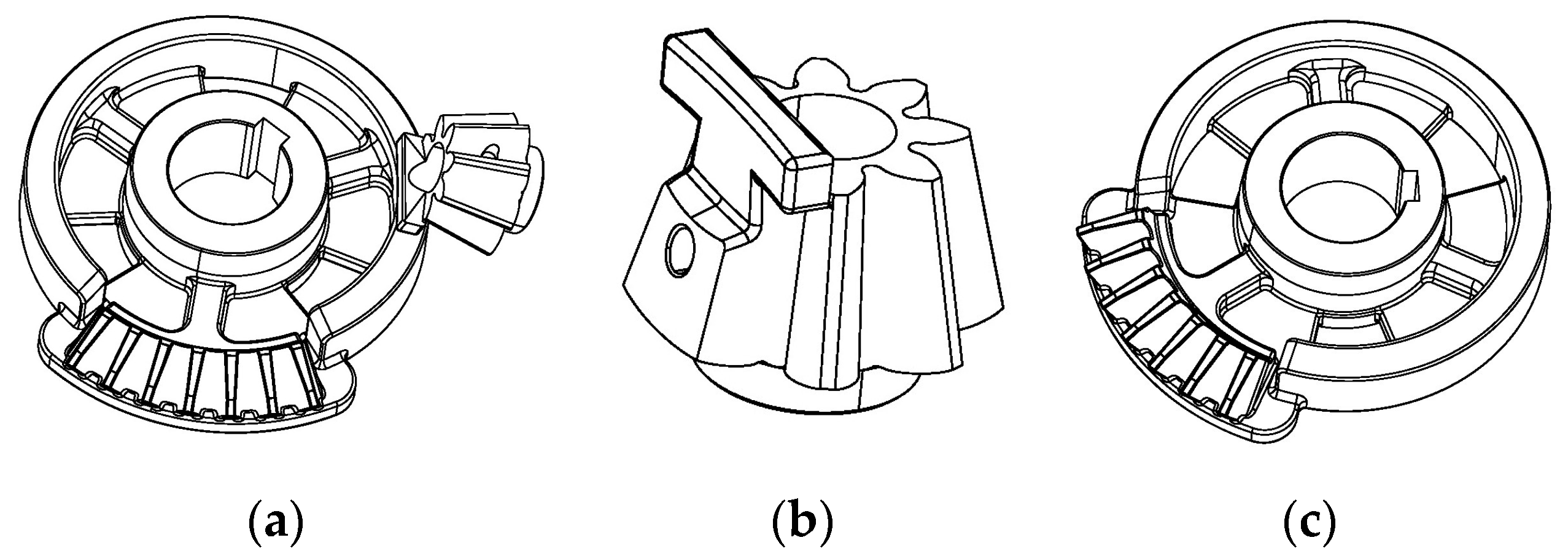
3. Design of the Transmission Structure of the Rope-Clamping Drive Mechanism in a Knotter with Double Synclastic Fluted Discs

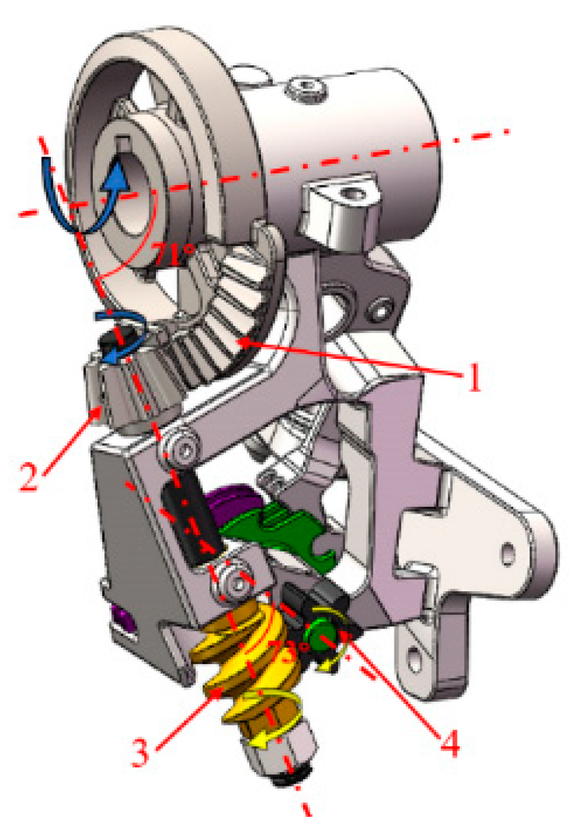
3.1. Design of Bevel Gear Transmission with Intersecting Axis Angle of 71°

In order to maintain the position of the involute helical gear axis, it is essential to consider the axial installation space limitations of knotters, and the optimal shaft intersection angle of the incomplete bevel gear transmission of the rope-clamping drive mechanism is preferred to be 71°. In accordance with the specific transmission requirements and general mechanical design principles [13,14,15], the key parameters of the bevel gear transmission with an intersecting axis angle of 71° are as shown in Table 1.
The joint design method of GearTrax and SolidWorks can be employed to generate the solid model of an incomplete bevel gear pair. First, the bevel gear transmission parameters shown in Table 1 and the tooth profile settings were set in GearTrax to obtain an accurate three-dimensional model of the bevel gear pair. Subsequently, according to the specific transmission requirements of the knotter, a secondary structural design for the bevel gear pair generated by GearTrax was performed under SolidWorks. The completed bevel gear pair design is shown in Figure 3.

3.2. Design of Worm Drive with Spatial Staggered Shaft Angle of 73°

In order to reduce the helix angle of the helical gear, decrease the force exerted on the worm shaft by the helical gear, and improve the reliability of the rope-clamping drive mechanism, the original left-hand worm drive is modified to a spatial staggered axis right-hand involute worm drive in the new transmission scheme, with a preferred shaft intersection angle of 73° [16,17,18]. The main design parameters of the involute worm gear pair are shown in Table 2.
By using the KISSsoft parameterized design software, the precise modeling of the right-handed worm drive with a spatial staggered axis angle of 73° was achieved. First, by setting the relevant parameters of the right-handed worm drive in KISSsoft, the solid models were generated after model verification in KISSsoft. Subsequently, according to the specific transmission requirements of the worm drives in knotters, a secondary structural design for the involute worm gear pair generated by KISSsoft was performed under SolidWorks. The design of the completed involute worm gear pair is shown in Figure 4.

4. Dynamic Simulation of the Rope-Clamping Drive Mechanism

On the premise of ensuring that the rotation phase of the rope-clamping disc remains unchanged, with the design goal of improving the reliability of the rope-clamping drive mechanism, its kinematic design and structural optimization were carried out. In order to demonstrate the performance of the redesigned rope-clamping drive mechanism, two virtual prototype models of knotters with double-fluted discs were established using the ADAMS software [19,20,21], and a flexible tying rope was added to obtain the dynamic simulation model, as shown in Figure 5. The overstepping function ‘STEP’ of ADAMS was used to control the tension of the rope, maintaining tension of 220 Newtons from 0 to 0.48 s and rapidly decreasing to 0 Newtons between 0.48 and 0.5 s.

4.1. Simulation and Analysis of Incomplete Bevel Gear Transmission with Intersecting Axis Angle of 71°

Based on a complete working cycle of 0.7 s for a knotter, the simulation time was set to 0.7 s with a step size of 300 steps in ADAMS. During the full-cycle simulation process, the meshing of the incomplete bevel gear pair and the surface fitting of the resting segment were both correct, as shown in Figure 6. The force curves of the bevel gear pair of the rope-clamping drive mechanism for the two types of knotters are depicted by the red and black curves in Figure 7.
From the comparison of the force curves shown in black and red in Figure 7, the meshing period of the bevel gear pair with double synclastic fluted discs is more in line with the force law of gear meshing. Moreover, during the resting segment, the mean force amplitude of the bevel gear pair in the knotter with double synclastic fluted discs is reduced by approximately one third compared to the bevel gear pair in the knotter with double reverse fluted discs, improving the force situation of the bevel gear.

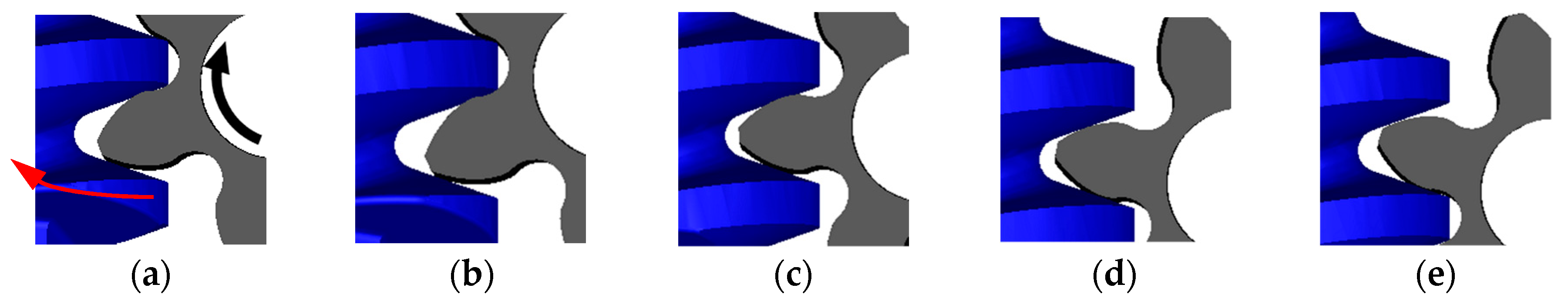
4.2. Simulation and Analysis of Involute Worm Drive with Spatial Staggered Shaft Angle of 73°

According to the transmission ratio of the helical gear driven by the worm, the worm rotates once, and the helical gear drives the rope-clamping disc to rotate 120 degrees. The meshing of the involute worm drive in the knotter with double synclastic fluted discs is correct, as shown in Figure 8. The force curves of the worm pair of the rope-clamping drive mechanism for the two types of knotters are depicted by the red and black curves in Figure 9.
From the motion simulation of the rope-clamping drive mechanism, it can be seen that the rope gripper completes the rope-clamping action when the worm gear pair engages between 0.36 s and 0.5 s. The comparison of the force curves shown in black and red in Figure 9 reveals that the redesigned worm drive has a peak force reduction of approximately one half compared to the original left-handed worm drive, indicating that the redesigned right-handed worm drive has better transmission performance and the force applied to the worm shaft will also be reduced.

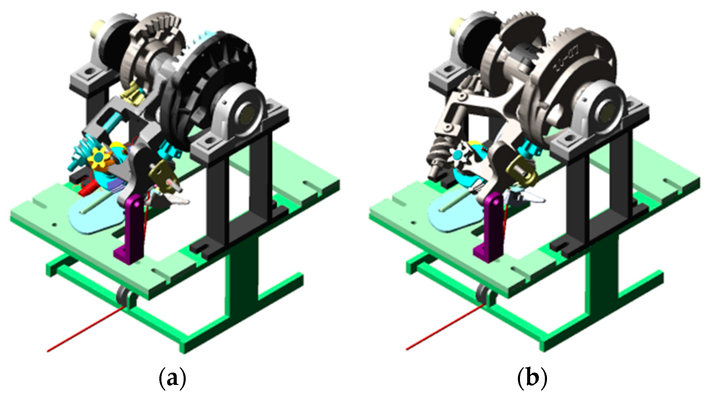
4.3. Virtual Simulation of the Rope-Clamping Drive Mechanism

In order to improve the computational efficiency and ensure the accuracy of the virtual rope-clamping simulations, the simulations used a single-strand rope model instead of the actual two-strand rope. The virtual rope-clamping processes based on the ADAMS dynamic simulation model are shown in Figure 10.
From Figure 10, it can be seen that the rope composed of micro-cylindrical segments is located in the groove of the rope-clamping disc in the initial position of the rope-clamping mechanism. When the rope-clamping drive mechanism acts, the rope-clamping disc rotates according to the phase relationship, and the rope follows the groove of the rope-clamping disc to move to the next phase. The results of the rope-clamping simulation are in line with the actual rope-clamping process of the rope-clamping disc.

5. Simulation of Rigid–Flexible Coupling Dynamics and Fatigue Life of the Rope-Clamp Drive Mechanism Based on the Collaborative Simulation of ADAMS and ANSYS

5.1. Simulation of Rigid–Flexible Coupling Dynamics of the Rope-Clamping Drive Mechanism

Considering that the worm shaft is susceptible to fatigue bending and fracture in the rope-clamping drive mechanism, it is necessary to simulate and predict the fatigue life of the worm shaft. Therefore, the ADAMS/ViewFlex module function was used [22,23,24,25,26]. The MNF flexible body neutral file, generated by ANSYS, was imported into the ADAMS rigid body dynamics model, and the original rigid model of the worm shaft was substituted. A rigid–flexible coupling dynamic simulation model of the knotter considering the flexibility of the worm shaft was established, as shown in Figure 11. The flexible worm shaft is shown in red in Figure 11.
Given that the two extremities of the worm shaft are, respectively, affixed with the bevel pinion and the worm, it is possible to approximate the force exerted on both ends of the worm shaft as the combined force acting on the bevel pinion and the worm. The simulation of the knotter’s rigid–flexible coupling dynamics is similar to the multi-rigid-body dynamics simulation. Contact constraints are added between the flexible worm shaft and its connected components, and the contact type is flexible body to rigid body. The force curves of the worm and the bevel pinion obtained from the simulation of the rigid–flexible coupling dynamics are shown in Figure 12a,b, respectively.
In the following fatigue simulation calculation of the worm shaft, the force acting on the bevel pinion and the force acting on the worm will be taken as the forces acting on the connection point between the worm shaft and the two components. The results of the rigid–flexible coupling dynamics simulation of the worm shaft will be used as the data input for its fatigue life simulation.

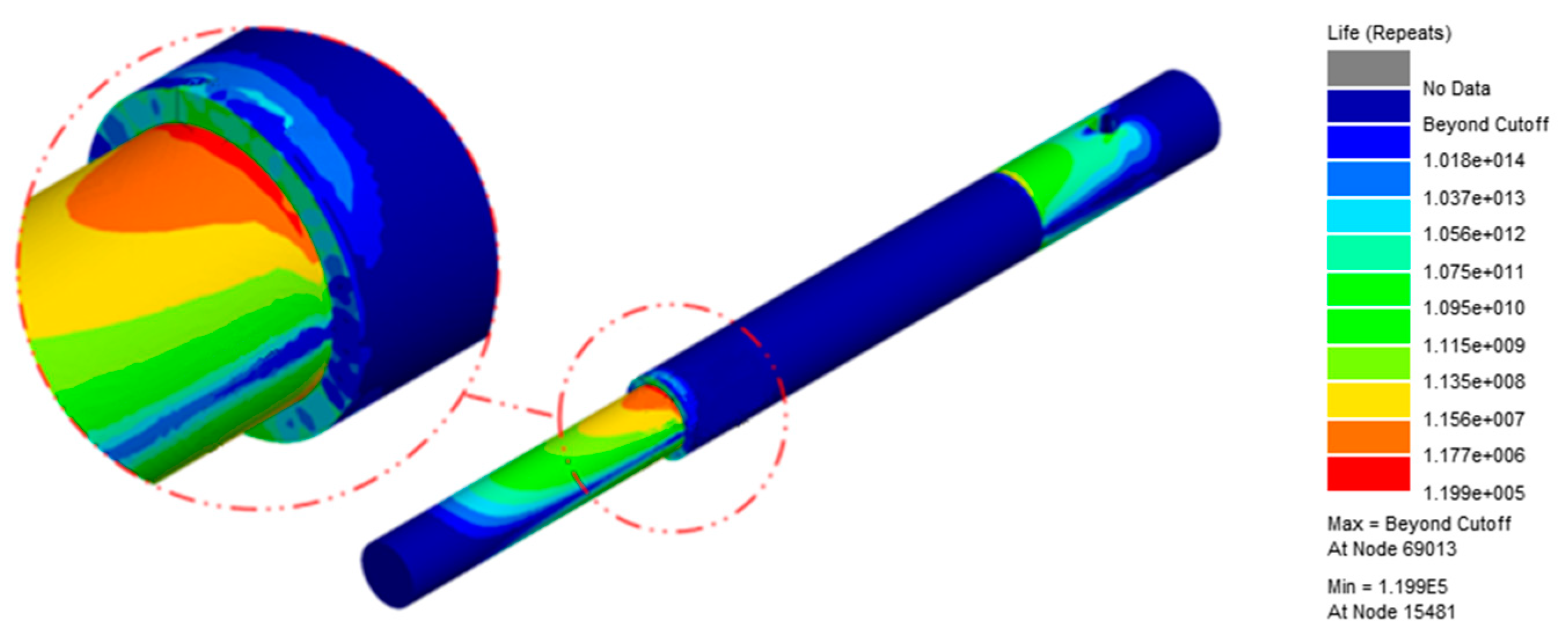
5.2. Simulation of the Fatigue Life of the Rope-Clamping Drive Mechanism

In this paper, the ANSYS nCode DesignLife fatigue simulation module is used to simulate and predict the fatigue life of the worm shaft. First, an ‘.rst’ format file was obtained for the static analysis of the worm shaft in the ANSYS WorkBench and then the static analysis results were input into ANSYS nCode DesignLife, with the load spectrum of the worm shaft obtained from Figure 12a,b used to calculate the fatigue life of the worm shaft. The detailed process is shown in Figure 13.
The material of the worm shaft is 40 Cr alloy steel, and the heat treatment process of the worm shaft is quenching and tempering. The anticipated survival rate of the worm shaft is set to 95% in ANSYS nCode DesignLife. The cloud diagram of the fatigue life simulation of the worm shaft is shown in Figure 14.
The minimum fatigue life of the worm shaft occurs at the shoulder of the shaft connecting the worm and the worm shaft, with significant stress concentration. The simulation results for the fatigue failure of the worm shaft are highly consistent with the actual situation. The minimum fatigue life of the worm shaft is 1.199 × 10⁵ times, which exceeds the service life requirement of 100,000 times determined by the knotter industry standard. From the perspective of theoretical simulation, the expected lifespan goal for the reliability improvement of the rope-clamping drive mechanism was achieved.

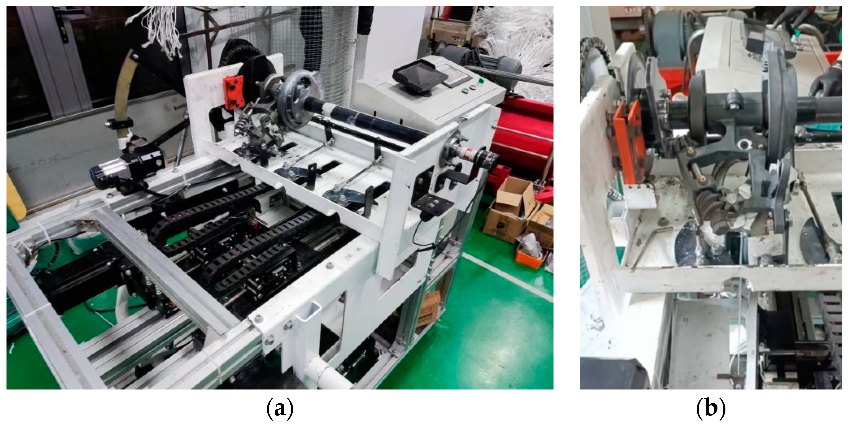
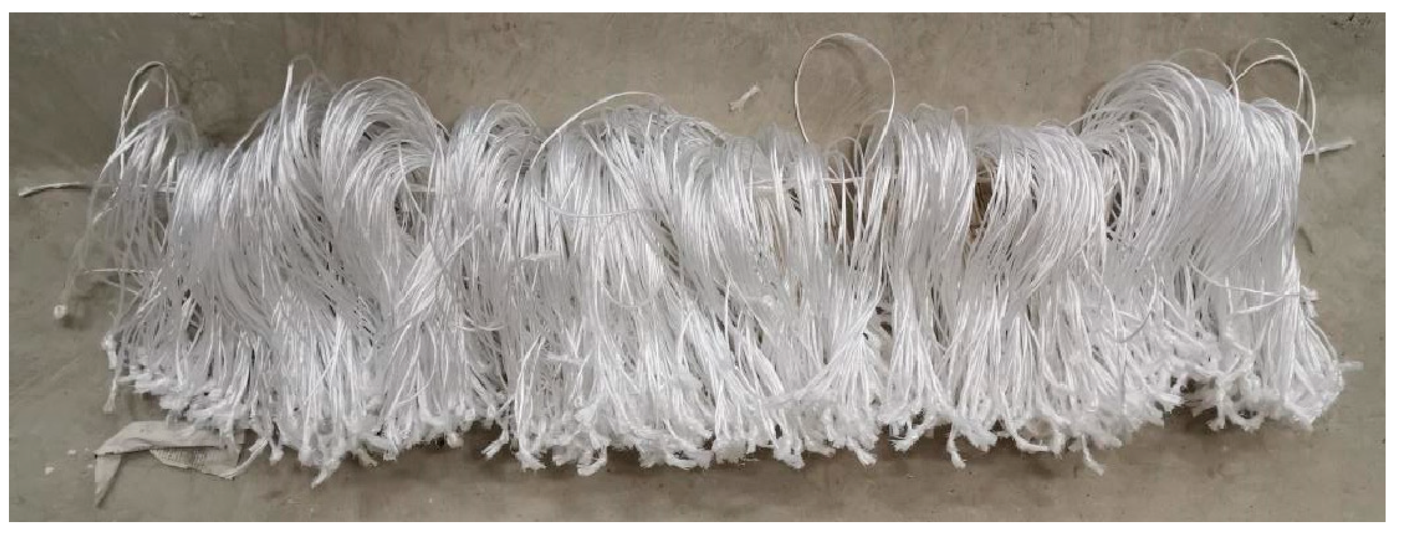
6. Reliability Test of the Rope-Clamping Drive Mechanism

In order to verify the reliability of the rope-clamping drive mechanism and the actual minimum fatigue life of the worm shaft, two knotters with double synclastic fluted discs were trial-produced and installed on a fatigue test bench for a rope-knotting test to determine the success rate of the rope-clamping action and the service life of the worm shaft due to fatigue failure, as shown in Figure 15.
Tests of the rope-gripping action were carried out, as shown in Figure 15. From the rope-clamping process shown in Figure 16, it can be seen that the action of the rope-clamping drive mechanism is consistent with the simulation results, and it can drive the rope gripper to reliably grip the rope on the rope needle.
A total of 5000 knotting tests with tying ropes did not result in rope-clamping failure, which proves the effectiveness of the rope-clamping drive mechanism design. The rope knots are shown in Figure 17.
In order to reduce the testing time to verify the minimum fatigue life of the worm shaft, the fatigue test bench adopted a fast-knotting mode without considering the success rate of knotting. This allowed the rope-clamping drive mechanism to operate continuously for 210 h at a speed of 90 revolutions per minute, which is equivalent to 113,400 knots. The worm shaft did not exhibit fatigue bending failure.
After 113,400 knots, two trial-produced knotters were installed on a baler, and experiments on the bundling of rice straw were conducted at a base in Jiangsu Province, as shown in Figure 18. After the bundling of 5400 bags of rice straw, the worm shaft did not experience fatigue fracture.
Based on the above three tests, the total work number of the rope-clamping drive mechanism reached 123,800, exceeding the minimum fatigue life obtained through the simulations. This indicated that the parameters of the rope-clamping drive mechanism were correctly matched, and the worm shaft parameters and heat treatment method were appropriate.

7. Conclusions

The joint application of the GearTrax, KISSsoft, and SolidWorks software can be used to effectively design rope-clamping drive mechanisms with spatial structures, perform accurate solid modeling, and provide a reference for other complex spatial transmission designs. A rigid–flexible coupling dynamics model of a knotter with a flexible worm shaft can be established based on the collaborative use of ADAMS and ANSYS, and the fatigue life of the worm shaft can be analyzed using ANSYS nCode DesignLife, which is capable of predicting the fatigue life of weak parts. The operation test results of the rope-clamping drive mechanism indicate that the redesigned rope-clamping drive mechanism is reliable in transmission, with a rope-clamping success rate of 100%. The actual operation times of the worm shaft exceed the minimum fatigue life obtained through joint simulation. The applied joint simulation method has high simulation accuracy.

Author Contributions

Conceptualization, Z.C. and H.W.; methodology, J.Y.; writing—original draft preparation, Z.C.; writing—review and editing, S.L., Y.G. and L.W. All authors have read and agreed to the published version of the manuscript.

Funding

This research was funded by the National Natural Science Foundation of China, grant number 52375248.

Institutional Review Board Statement

Not applicable.

Data Availability Statement

The datasets supporting the conclusions of this article are included within the article.

Acknowledgments

The authors thank the anonymous reviewers and journal editor for their valuable suggestions, which helped to improve the manuscript. Moreover, they would like to thank Zhou for helping with the work.

Conflicts of Interest

The authors declare no conflicts of interest.

References

  1. Yin, J.J.; Zheng, J.; Wang, X.X.; Zhu, H. Analysis of Rope-twining Failure of Knotter Hook and Its Improved Design of Curved Surface Shape. Trans. Chin. Soc. Agric. Mach. 2018, 49, 82–89. [Google Scholar] [CrossRef]
  2. Huang, S.T.; Hu, C.; Lv, J.J.; Ma, L.; Ying, F. Key parameters of knotting process of new knot tying device. J. Mech. Electr. Eng. 2018, 3, 261–265. [Google Scholar]
  3. Yin, J.; Zhang, W.; Chen, Y.; Gao, Q. Design and Knotting Test Analysis of Knotter Driven by Double Gear-discs. Trans. Chin. Soc. Agric. Mach. 2016, 47, 98–105. [Google Scholar]
  4. Yu, X.; Chen, L.; Wu, M.; Zhang, J. Simulation and Experiment of D-bale Based on Multi-body Dynamics. Master’s Thesis, Anhui Agricultural University, Hefei, China, 2017. [Google Scholar]
  5. Zhang, A.; Chen, L.; Dong, H.; Zhang, S.; Li, H.; Han, L. Spatial Structure Parameter Analysis of Rope Cutting and Releasing Mechanism of D-knotter. Trans. Chin. Soc. Agric. Mach. 2017, 48, 73–80. [Google Scholar]
  6. Li, H.; Xiong, Y.; Chen, L.; Zhang, S.; Li, X.; Han, L. Wear Research and Improved Design of D-knotter Wiper Mechanism. Trans. Chin. Soc. Agric. Mach. 2015, 46, 118–124. [Google Scholar]
  7. Ma, W. Reliability Research on Knotter of Square Baler. Master’s Thesis, Inner Mongolia Agricultural University, Hohhot, China, 2021. [Google Scholar]
  8. Na, R.; Liu, Y. Random Vibration Analysis and Structural Optimization of the D-Knotter Frame. Comput. Simul. 2021, 38, 235–241. [Google Scholar]
  9. The Newfoundland circular knotter won the gold medal at the Edison Invention Award in 2021. Agric. Mach. 2021, 8, 36.
  10. Feuerborn, B. Krone Ballenpressen neuer Knoter ohne Schnipsel [EBOL]. 25 February 2022. Available online: https://www.agrarheute.com/technik/krone-ballenpressen-neuer-knoter-ohne-schnipsel-590703 (accessed on 20 October 2023). (In German).
  11. Shuang, Z.; Cen, H.T.; Si, X.K. Frame body structural design and modal analysis of D-type double knotter. J. Mach. Des. 2021, 38 (Suppl. S2), 118–122. [Google Scholar]
  12. Zhang, Y.; Zhu, L.Y.; Gou, X.F. Calculation methods of load distribution ratio for spiral bevel gear. Int. J. Mech. Sci. 2023, 257, 108531. [Google Scholar] [CrossRef]
  13. Song, C.S.; Zhu, C.C.; Lim, T.C.; Luo, J.Y.; Xu, X.Y. Time-varying mesh characteristics of beveloid gears with crossed axes and small shaft angle. J. Vib. Shock. 2012, 31, 153–157. [Google Scholar]
  14. Chen, Z.; Zhou, J.; Liu, B.; Fu, H.; Meng, X.; Ji, J.; Zhang, Y.; Hua, X.; Xu, X.; Fu, Y. Meshing frictional characteristics of spur gears under dry friction and heavy loads: Effects of the preset pitting-like micro-textures array. Tribol. Int. 2023, 180, 108296. [Google Scholar] [CrossRef]
  15. Ma, L.Z.; Xie, J.; Yin, X.Q. Principle and Design of Mechanism, 2nd ed.; China Machine Press: Beijing, China, 2015. [Google Scholar]
  16. Xu, X.Y.; Li, L.; Ren, B.; Zhu, C. Study on the Dynamic Characteristics of Herringbone Planetary Gear System with Space Shafts Angle. J. Mech. Eng. 2023, 59, 141–150. [Google Scholar] [CrossRef]
  17. Zhou, M.L.; Yang, J.J.; Xu, T.B.; Ying, J.; Wang, X. Optimal design of transplanting mechanism with differential internal engagement non-circular gear trains. J. Agric. Eng. 2022, 53, 1–10. [Google Scholar] [CrossRef]
  18. Guo, E.K.; Hu, L.L.; Zhang, E.Z.; Liu, C.; Xu, J.; He, W. A Cylindrical Skiving Tool Design Method Based on a Conjugate Surface for Internal Gear Manufacture. J. Manuf. Process. 2023, 101, 1538–1550. [Google Scholar] [CrossRef]
  19. Qiao, G.; Liao, R.; Guo, S.J.; Shi, Z.; Ma, S. Design and Dynamic Analysis of the Recirculating Planetary Roller Screw Mechanism. Chin. J. Mech. Eng. 2022, 35, 87. [Google Scholar] [CrossRef]
  20. Huang, J.C.; Tan, L.; Tian, K.P.; Zhang, B.; Ji, A.; Liu, H.; Shen, C. Formation mechanism for the laying angle of hemp harvester based on ANSYS-ADAMS. Int. J. Agric. Biol. Eng. 2023, 16, 109–115. [Google Scholar] [CrossRef]
  21. Li, X.F.; Wang, Y.B. Analysis of mixed model in gear transmission based on ADAMS. Chin. J. Mech. Eng. 2012, 25, 968–973. [Google Scholar] [CrossRef]
  22. Huang, T.; Zhao, J.X.; Song, K.X.; Zhang, X.; Jiang, Y.; Hao, L. Fatigue Life Research of Bellows under Coupled Loading of Velocity and External Pressure Based on S-N Curve of Components. J. Mech. Eng. 2022, 58, 269–282. [Google Scholar] [CrossRef]
  23. Fu, Q.; Wang, D.D.; Zhang, R.Y.; Lu, Y.; Wang, R.; Zhu, R. Stress Analysis and Stress Fatigue Life Prediction of Rcp Impeller Based on Fluid-thermal-solid Coupling. Nucl. Eng. Des. 2023, 414, 112596. [Google Scholar] [CrossRef]
  24. Li, F.Z.; Tong, S.G.; Wang, X.B.; Cheng, X.M. Rigid-flexible coupling dynamics and characteristics of marine excavator’s mechanical arm. J. Vib. Shock. 2014, 33, 157–163. [Google Scholar]
  25. Zheng, T.; Zhang, D.G. Limitations of MSC.ADAMS for High speed and Large Deformation Problems of Rigid flexible Coupling Systems. J. Nanjing Univ. Ence Technol. 2012, 36, 993–998. [Google Scholar]
  26. Wu, D.; Ding, D.; Cui, B.; Jiang, S.; Zhao, E.; Liu, Y.; Cao, C. Design and experiment of vibration plate type camellia fruit picking machine. Trans. Chin. Soc. Agric. Eng. 2022, 15, 130–138. [Google Scholar] [CrossRef]
Figure 1. Transmission diagrams of the rope-clamping drive mechanism. (a) A knotter with double reverse fluted discs; (b) a worm shaft failure in a knotter with double reverse fluted discs; (c) the force acting on the worm shaft. The individual components in (a) are (1) the bevel gear on a small fluted disc; (2) an incomplete bevel pinion; (3) a left-hand worm; (4) a helical gear.
Agriculture 14 01254 g001
Figure 2. A novel transmission scheme for the rope-clamping drive mechanism in a knotter with double synclastic fluted discs. The individual components are (1) a bevel gear on a small fluted disc; (2) an incomplete bevel pinion; (3) a right-hand worm; (4) a helical gear.
Agriculture 14 01254 g002
Figure 3. Bevel gear pair. (a) Assembly diagrams; (b) bevel pinion; (c) bevel gear on small fluted disc.
Agriculture 14 01254 g003
Figure 4. Involute worm gear pair. (a) Right-handed worm; (b) helical gear; (c) assembly diagram.
Agriculture 14 01254 g004
Figure 5. The dynamic simulation model of a knotter. (a) A knotter with double reverse fluted discs; (b) a knotter with double synclastic fluted discs.
Agriculture 14 01254 g005
Figure 6. Meshing processes of incomplete bevel gear pair. (a) Start of meshing; (b) meshing process I; (c) meshing process II; (d) meshing process III; (e) resting surfaces prior to contact; (f) surface fitting of resting segment.
Agriculture 14 01254 g006
Figure 7. Force curves of the bevel gear pair of the rope-clamping drive mechanism for the two types of knotters.
Agriculture 14 01254 g007
Figure 8. Meshing processes of involute worm drive. (a) Start of meshing; (b) meshing process I; (c) meshing process II; (d) meshing almost complete; (e) end of meshing. The illustration depicts the direction of rotation of the right-handed worm (red arrow) and the helical gear (black arrow).
Agriculture 14 01254 g008
Figure 9. Force curves of the worm pair of the rope-clamping drive mechanism for the two types of knotters.
Agriculture 14 01254 g009
Figure 10. Simulation of rope-clamping processes. (a) Initial position; (b) start of rope clamping; (c) rope-clamping process I; (d) rope-clamping process II; (e) end of rope-clamping.
Agriculture 14 01254 g010
Figure 11. Rigid–flexible coupling dynamic simulation model of the knotter.
Agriculture 14 01254 g011
Figure 12. Force curve. (a) Force curve of the worm; (b) force curve of the bevel pinion.
Agriculture 14 01254 g012
Figure 13. Flow chart for fatigue life simulation of rope-clamping drive mechanism.
Agriculture 14 01254 g013
Figure 14. The cloud diagram of the fatigue simulation analysis of the worm shaft.
Agriculture 14 01254 g014
Figure 15. The fatigue test bench for the knotter and rope-knotting test. (a) Overall structure of the fatigue test bench of the knotter; (b) partial enlarged view of the trial-produced knotter.
Agriculture 14 01254 g015
Figure 16. The test of the rope-gripping action. (a) Before rope-gripping; (b) about to grip the rope; (c) during rope gripping; (d) end of rope-gripping action.
Agriculture 14 01254 g016
Figure 17. The rope knots of the 5000 knotting tests.
Agriculture 14 01254 g017
Figure 18. The experiments on the bundling of rice straw. (a) A baler installed with two trial-produced knotters; (b) a partial enlarged view of two trial-produced knotters installed on a baler.
Agriculture 14 01254 g018
Table 1. Key parameters of bevel gear transmission with intersecting axis angle of 71°.
Theoretical Gear TeethModule
(mm)
Pressure Angle
α (°)
Pitch Angle
δ (°)
Modification Coefficient x1 (mm)
Bevel Pinion842010.550.4396
Bevel Gear 3860.45−0.4396
Table 2. Main design parameters of the involute worm gear pair.
Gear TeethModule
(mm)
Normal Pressure Angle α (°)Helix Angle
β (°)
Lead Angle
γ (°)
Modification Coefficient x2 (mm)
Worm24.52076.7813.22−0.20
Helical Gear6−3.78−86.220.20
Disclaimer/Publisher’s Note: The statements, opinions and data contained in all publications are solely those of the individual author(s) and contributor(s) and not of MDPI and/or the editor(s). MDPI and/or the editor(s) disclaim responsibility for any injury to people or property resulting from any ideas, methods, instructions or products referred to in the content.

