Article

Research and Prediction of Wear Characteristics of Alfalfa Densification Die Based on the Discrete Element Method

1
College of Mechanical and Electrical Engineering, Inner Mongolia Agricultural University, No. 36 Zhaowuda Road, Hohhot 010018, China
2
Southwestern Institute of Physics, Chengdu 610041, China
3
Inner Mongolia Engineering Research Center for Intelligent Equipment for the Entire Process of Forage and Feed Production, Hohhot 010018, China
*
Author to whom correspondence should be addressed.
Agriculture 2024, 14(8), 1260; https://doi.org/10.3390/agriculture14081260
Submission received: 27 June 2024 / Revised: 23 July 2024 / Accepted: 29 July 2024 / Published: 31 July 2024
(This article belongs to the Section Agricultural Technology)

Abstract

:
In this study, the wear characteristics of the die were tested and analyzed through compaction tests, and the distribution of wear depth along the direction toward the extrusion outlet was obtained. A discrete element method (DEM) model of the die’s wear process was established. The results show that the severe wear area is located near the stop position of the compression rod, forming a plow-shaped wear area along the extrusion direction, accompanied by fatigue peeling. The wear depth gradually decreases towards the extrusion outlet. The DEM model partially reveals the occurrence of the wear phenomenon, but the particle motion speed deviates from the actual situation. The maximum compression force value range during the DEM compression stage is within the actual maximum compression force value range, and the relative error range of the average maximum compression force is less than 2%. By verifying the formula to calibrate the model, the calibrated model is compared with the actual mold wear, and the predicted value is close to the actual test result. The DEM can be used to explore the wear mechanism and predict the die’s wear failure process, laying the foundation for optimizing die wear resistance design.

1. Introduction

Traditional non-renewable fossil fuels such as oil and coal are the main drivers of climate change. Faced with the dual pressures of environmental change and resource depletion, the development and utilization of renewable energy are of crucial importance [1]. Biomass energy is a renewable and essential clean energy source [2]. Converting the widely available biomass in nature into biomass energy through chemical or physical methods can effectively improve the utilization of biomass resources [3]. Due to the low energy density and irregular shapes of biomass resources, compaction technology is one of the effective pretreatment methods for their utilization. Compaction involves crushing the loose biomass raw materials (fibrous biomass) and applying a certain pressure to form them, thereby overcoming the difficulties in transportation and storage caused by the loose and irregular shapes of biomass [4]. The leading compaction equipment currently used includes ring-die pellet mills, flat-die pellet mills, and extruder pellet mills [5], whose basic principle is that the material enters the compaction mold and is deformed under high pressure, gradually being compressed out of the mold as a result of friction with the mold wall. Therefore, the severe wear of the compaction mold is a common problem in compression equipment [6,7].
Researchers both domestically and internationally have conducted extensive studies on compacting alfalfa to improve product quality and reduce compaction pressure. Wang [8] compressed alfalfa pellets and found that with a small particle size (around 16 mesh), a moisture content of 16–18%, a vibration frequency of approximately 20 Hz, a molding time of 150 s, and an external temperature of 70 °C, the product quality was superior, facilitating stress transmission during compaction. The moisture content significantly affects the physical properties of alfalfa pellets. Du [9] explored the impact of vibrational fields on alfalfa compaction, discovering that during open compression with a vibration frequency of 15 Hz, the moisture content (15–20%) notably influences the compacting pressure. Lower moisture content results in smaller forming pressure and poorer quality; conversely, higher moisture content leads to greater forming pressure and better quality. Du et al. [10] conducted compaction tests on crushed alfalfa particles (with a particle size of less than 10 mm), finding that under conditions of a 15% moisture content and a compression force of 35 kN, the density of the compacted alfalfa blocks was relatively good.
After the wood and corn mixture is crushed, friction and wear occur when the forming hole and the forming particle come into contact, leading to the increase in the diameter of the forming hole and the diameter of the forming particle; at the same time, with the rise of the particle size, the density and hardness of the forming particle decreased [11]. Wang studied the wear condition of the roll press forming machine. It was found that increased side pressure and resistance lead to accelerated wear and a shortened service life [12].
The mechanisms of wear formation in biomass engineering are complex, primarily encompassing abrasive wear, erosion wear, abrasive particle wear, fatigue wear, adhesive wear, and corrosion wear [13]. Abrasive particle wear was classified as micro-cutting wear and fatigue damage from plastic deformation induced by high stress. Ren et al. researched the compaction process of licorice powder (below 300 mesh). Microscopic observations of the die surface revealed that the mold is mainly affected by abrasive particle wear, adhesive wear, and fatigue wear [14]. Zhou et al. studied different die for various materials that exhibited distinct wear mechanisms during pelletizing, yet overall, plastic deformation and cutting were the primary mechanisms leading to material loss [15]. The experiments on improving the wear resistance of die surface coatings revealed that the main wear mechanisms comprised fatigue wear and abrasive wear. Furthermore, the coatings’ hardness and elastic modulus influenced wear performance significantly [14]. Chen et al. found that the wear at the inlet of the forming mold is the most serious, and the wear gradually decreases along the direction of the mold outlet [16]. Wen’s analysis of the stress and motion of biomass in the screw extruder found that the areas with stress concentration have severe wear [17]. In the densification process of biomass, the main wear mechanisms are abrasive particle wear and fatigue wear. Abrasive particle wear primarily manifests as micro-cutting and plastic deformation fatigue damage.
With the continuous development of computer simulation technology, integrating the discrete element method with wear models has gradually emerged as a pivotal method for studying stress distribution and wear conditions in discrete material mechanical processing. Argatov et al. utilized a Hertzian contact configuration as the contact model between the material and the workpiece during the numerical derivation process. They adopted Archard’s wear as the wear model. These choices provided an excellent fitting effect for the numerical simulation [18]. Capozza et al. [19] combined the discrete element method and the Archard wear model to observe the microscopic interactions between particles and the mold. This can effectively simulate the evolution of the surface to describe the failure model of wear. Sun et al. [20] used the DEM to simulate the motion behavior and force chain distribution of particulate materials in a screw conveyor. The motion of the particles and the related distribution of contact forces profoundly impact the distribution of wear rates, leading to changes in the wear rate trend. Yu et al. [21] developed the Oka wear model using the discrete element method to simulate the impact wear of solid particles on pipelines, showing good agreement between the simulation and experimental results. Among them, verifying the consistency between the discrete element model and actual experiments is particularly important. Du et al. [22] utilized the compression stage mechanics transformation law and maximum compression force comparative analysis to determine their consistency and established a discrete element model for alfalfa dense compression. Zhao [23] combined the DEM and Archard’s wear model to investigate the impact of operating conditions on the wear of the drum and blades and optimized the operating conditions for the drum and blades, verifying the accuracy of the model by comparing the wear location and wear amount from the actual experiment with the results of the simulation test. This indicates that based on the DEM, combined with the wear model, an effective method has been provided to predict the wear condition of the forming mold, which is another means of exploring the wear mechanism from a microscopic perspective.
Therefore, this paper utilizes a combination of experiments and simulations to perform a microscopic analysis of the surface of the die after a certain period of densification. Based on the stress analysis of the die during the densification process, the die’s stress distribution, transmission, and wear mechanism are analyzed at the microscopic level using the discrete element method and wear models. This proposes a reasonable method for predicting die wear and explores the accuracy and precision of the predictive model in forecasting die wear.

2. Materials and Methods

2.1. Materials

The alfalfa samples were collected from the initial harvest of the experimental field at the Inner Mongolia Agricultural University in Hohhot, China. Subsequently, they were processed using a crusher, yielding crushed alfalfa with a length of less than 10 mm. Place the prepared 100 g grass sample in a drying oven at 60 °C for 10 h to determine the moisture content of the alfalfa particles. Based on the actual moisture content of the alfalfa particles, use a spray bottle to lightly mist the alfalfa particles with an appropriate amount of water, then thoroughly mix them. Subsequently, use a portable moisture meter (high-precision MS-H feed moisture meter, measurement range 0–84%, accuracy range 1%, Qingdao Tuoke Instrument Co., Ltd., Qingdao, China) to measure the moisture content of the reconstituted alfalfa, ensuring the moisture content of the alfalfa particles is 15% ± 1%. Then, select a 100 g sample and place it in a drying oven at 60 °C for 10 h to determine the moisture content of the test-crushed alfalfa particles.

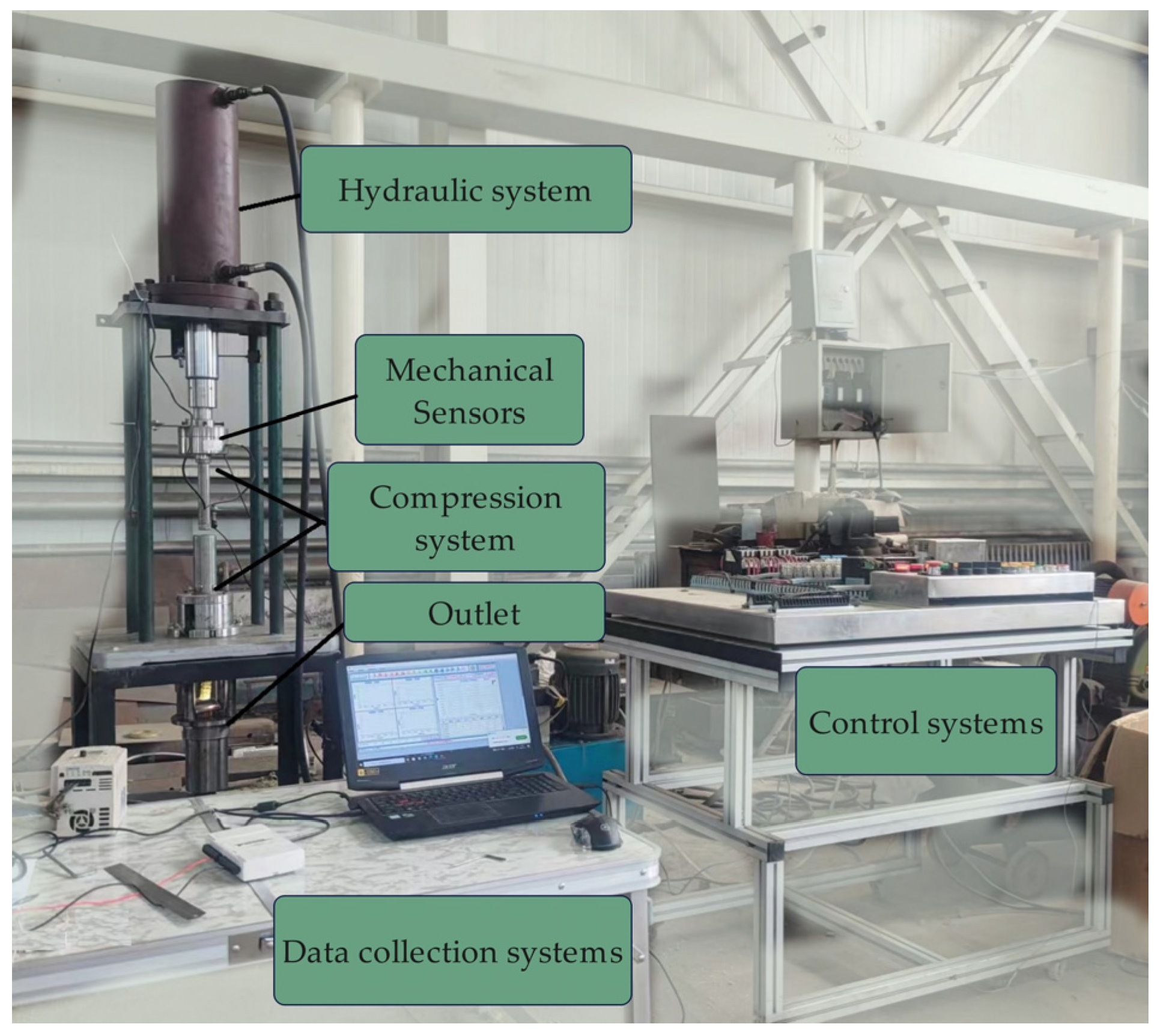
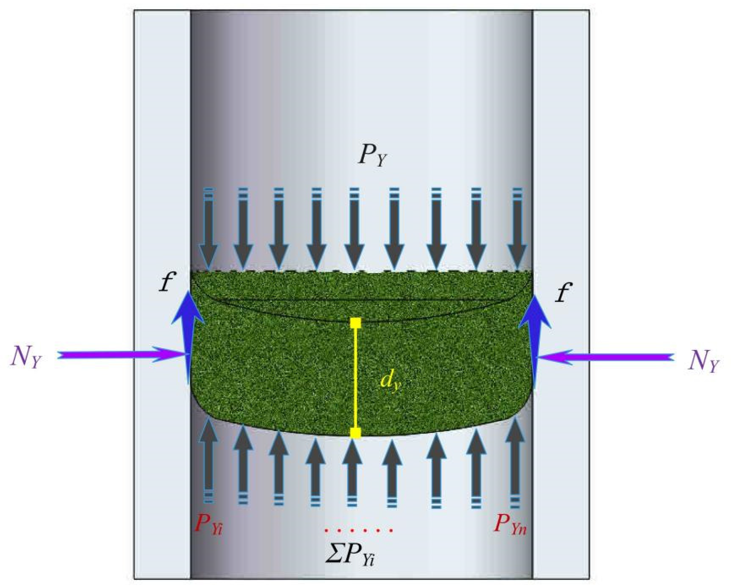
2.2. Experimental Principles

The mechanical equipment is a self-designed multi-functional piston compressor based on the principle of piston compression molding, as shown in Figure 1. A total of 10 g of loose alfalfa particles are filled into a 30 mm diameter, 146 mm long feed chamber. The compression rod moves downward at a speed of 5 mm/s, compacting the loose material to the maximum extent. Under the action of the compression rod, the compacted material is then pushed into the forming area of the die. When the compression rod reaches the stop position, it retracts, and one compression cycle is completed. The briquette moves towards the mold outlet through the continuous filling and compression displacement process and forms an alfalfa briquette after passing through the 156 mm molding cavity (Figure 2). The die material is 45 steel with a hardness of 23 HRC, and the mold cavity has undergone the final machining process using the boring technique, resulting in a surface roughness 6.3. The ambient temperature during the experiment was around 20 °C, and the relative humidity of the air was 20%. The mechanical sensor (Rim-type tension and compression pressure sensor, model 10 t, Hengyuan Sensor Technology Co., Ltd., Bengbu City, China, sensitivity 2.0 ± 0.05 mV/V, range ±10 t.) installed on the top of the piston collects the compression force values during the compaction process. At the stopped position of the press rod, a through-hole with threading is machined on the mold, and a PT100 class A threaded temperature sensor (Xinghua Suma Electrical Instruments Co., Ltd., Xinghua, China, measurement range −50~200 °C) is fixed in this hole. The temperature measurement point at the sensor’s tip is tangent to the inner wall surface of the mold. The temperature value of the inner wall surface of the mold during the compression process is measured.
The relatively low mold hardness makes it more susceptible to wear and tear [24], so the work time was shorter. After approximately 10 h (around 800 cycles) of production, the mold was removed for observation and study. The diameter of the die post-wear was measured using a vernier caliper to ascertain cumulative wear at different positions. Using a 30× magnification high-definition stereo microscope (3800-D high-definition electronic microscope, Dongxing Technology, Shenzhen, China) with a 1.0 objective lens and an LED light source as supplementary illumination, the microscopic wear condition of the mold cavity surface was observed.

3. Discrete Element Simulation Experiment

3.1. Interaction Model

The contact model in discrete element analysis defines the mechanical interaction between particles. The Hertz–Mindlin (no-slip) model was chosen to represent the interaction between alfalfa and the die, considering the alfalfa compaction process’s physical properties and the materials’ mechanical interaction. Additionally, the EEPA model was used to illustrate the interaction between alfalfa particles [25], incorporating a nonlinear hysteresis spring model to provide a comprehensive understanding of elastoplastic contact deformation, which is a key aspect of the compaction process depending on plastic contact deformation [26]. The wear models utilized for the material-to-die interaction consist of the Archard wear model and the Oka wear model. In this context, the Archard wear model is employed to predict wear based on the frictional distance and contact normal force [27]; the cumulative wear depth is calculated using Equations (1) and (2) in the EDEM2023 software for the Archard wear model.
Q = W A r F n d t ,
w e a r   d e p t h = Q A ,
where Q represents the volume of wear; W A r denotes the wear constant in the Archard wear model within the EDEM software, with units of 1/Pa; F n represents the normal force between the particle and the die; d t signifies the distance of tangential movement; and A represents the contact area between the surfaces.
Meanwhile, the Oka wear model predicts the material volume removal caused by particle impact. Its principle is to calculate the volume of erosion wear based on the particle size, impact velocity, and impact angle (Equations (3) and (4)) [28].
d w = g ( α ) E ( α ) m A ,
E ( α ) = 65 W k 1 ( v 104 ) 2.3 H v 0.038 ( D 0.326 ) 0.19 ,
where d w is the wear depth, α is the particle impact angle, g(α) is the impact angle dependence of normalized erosion, E(α) is the wear volume per unit mass, m is the mass of the particle and A is the geometry element area. W is the material’s wear constant, v is the particles impact velocity, Hv is the Vickers hardness of worn material, D is the particle diameter and k1 is an experimentally derived coefficient.

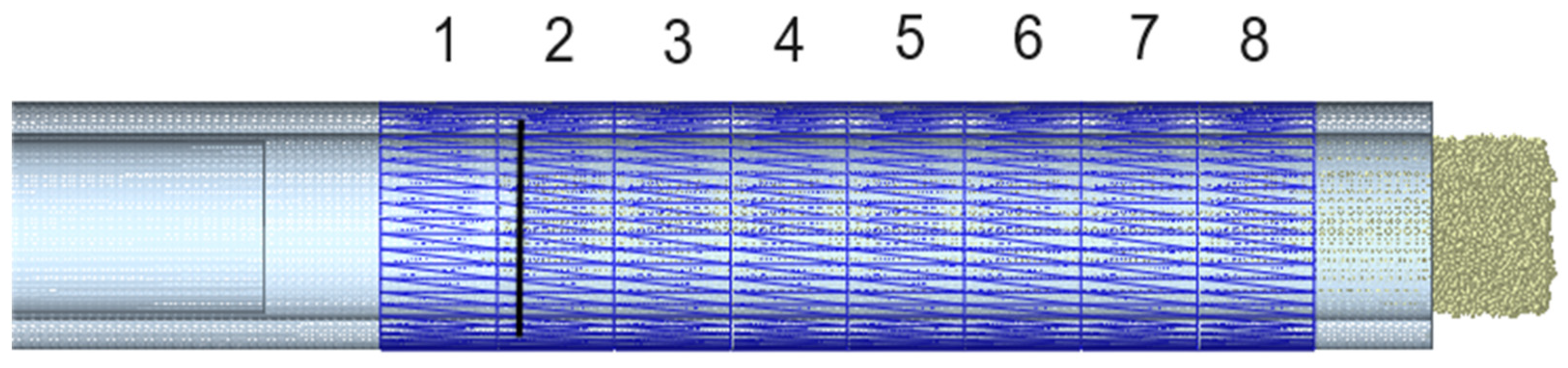
3.2. Particle Model and Die Model

Particle behavior modeling requires a nuanced approach, mainly when dealing with compaction and complex particle interactions. Refraining from substituting one type of particle for another may lead to inaccuracies in prediction [26]. The sieved crushed alfalfa particles are divided into four grades after crushing based on the shape and proportion of the granules in each grade, as shown in Figure 3. The die model is built using Solidworks 2020 software and meshed, with the mesh parameters being facets of 52,720 and nodes of 26,344 (Figure 4).

3.3. Particle Model and Die Model

In the DEM process, the compression speed of the push rod is 5 mm/s, and the particulate material is generated in a static one-time manner with an initial velocity of 500 mm/s when falling. The time step is 1.432 × 10⁻⁷ s, and the storage time interval is 0.01 s. Notably, the 3 Rmin discrete unit, a key component, generated a more reasonable grid size in the DEM simulation, significantly contributing to the saving of simulation time and the resolution of the contact problem.
To better analyze die wear, it is necessary to measure the changes in the pressure on the die, the compression force on the alfalfa particles, and the normal force between the particle contacts during the compaction process. Therefore, the main working area of the forming die is divided into eight small areas from top to bottom (Figure 4). Each small area has a height of 20 mm, with a total measurement range from 20 mm to 180 mm.

3.4. DEM Parameter Settings

Based on the discrete element test plan and material properties, the simulation parameters for the discrete element are determined [22,29,30], and they are shown in Table 1.

4. Results and Discussion

4.1. Die Wear Analysis

4.1.1. Results of the Experiment

After the material was compressed multiple times, the pressure value of the densification process stabilized within the range of 66.41 to 72.97 kN. The pressure variation curve of a single compression process is shown in Figure 5. The mold’s inner surface temperature was within the range of 39.2 °C to 42.0 °C. The density of the compacted alfalfa blocks was between 850 and 978 kg/m3.

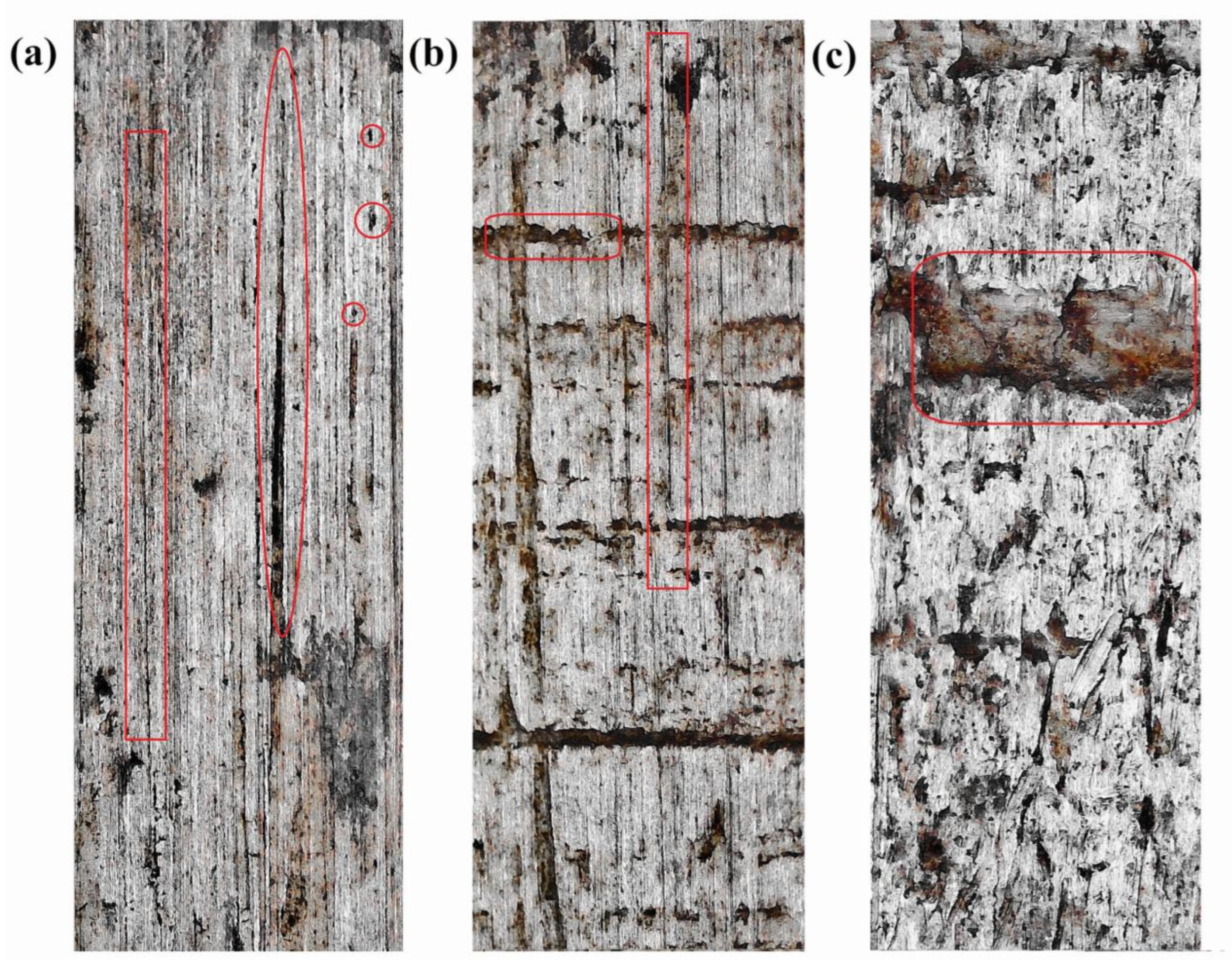
4.1.2. Microscopic Observation of the Mold Working Surface

After performing microscopic observation on the mold surface after a certain number of compression test cycles, the wear depth of the die inner wall gradually decreases along the compression direction, and the wear reaches the maximum value at the end of the compression stroke. During the densification process, the relatively hard alfalfa particles cut the inner wall of the die along the extrusion direction, forming furrows and pits. Three observation windows were selected to analyze the mold wear in detail (Figure 6), and the locations of the observation parts are shown in the a, b, and c marked areas in Figure 2.
At the upper end a of the die, observe that the original surface features of the mold cavity have disappeared, replaced by furrows (as shown by the rectangular area in the figure) that are significantly wider and deeper. This phenomenon indicates that in this region, the compacted alfalfa and the mold surface have undergone a severe frictional interaction, leading to significant wear on the inner surface of the mold. Meanwhile, the hard particles in the material, under high-pressure conditions, have permeated the contact surfaces, causing abrasive wear. This wear is manifested as furrows on the mold surface, the width and depth of which visually reflect the severe compression and friction between the material and the mold in this area. Furthermore, plastic deformation (as shown by the oval in the figure) formed by high-stress compression can also be observed on the mold cavity surface. It is worth noting that some of the materials that have undergone plastic deformation have detached due to fatigue. Due to the lack of heat treatment of the mold material, its surface hardness is relatively low. The heat generated during the friction between the material and the mold further promotes the fatigue wear of the mold, exacerbating the overall wear situation. In addition to the above phenomena, the mold surface also has a certain number of pits, further confirming the complex wear process experienced by the mold surface. Throughout this process, the mold’s inner surface has undergone a continuous “cutting and peeling” cycle, with the newly exposed metal continuing to experience “abrasive wear”, → “fatigue wear”, → “metal peeling”, → “abrasive wear.” At the macro scale, this has resulted in an increasing depth of wear, and the actual diameter of the die has increased.

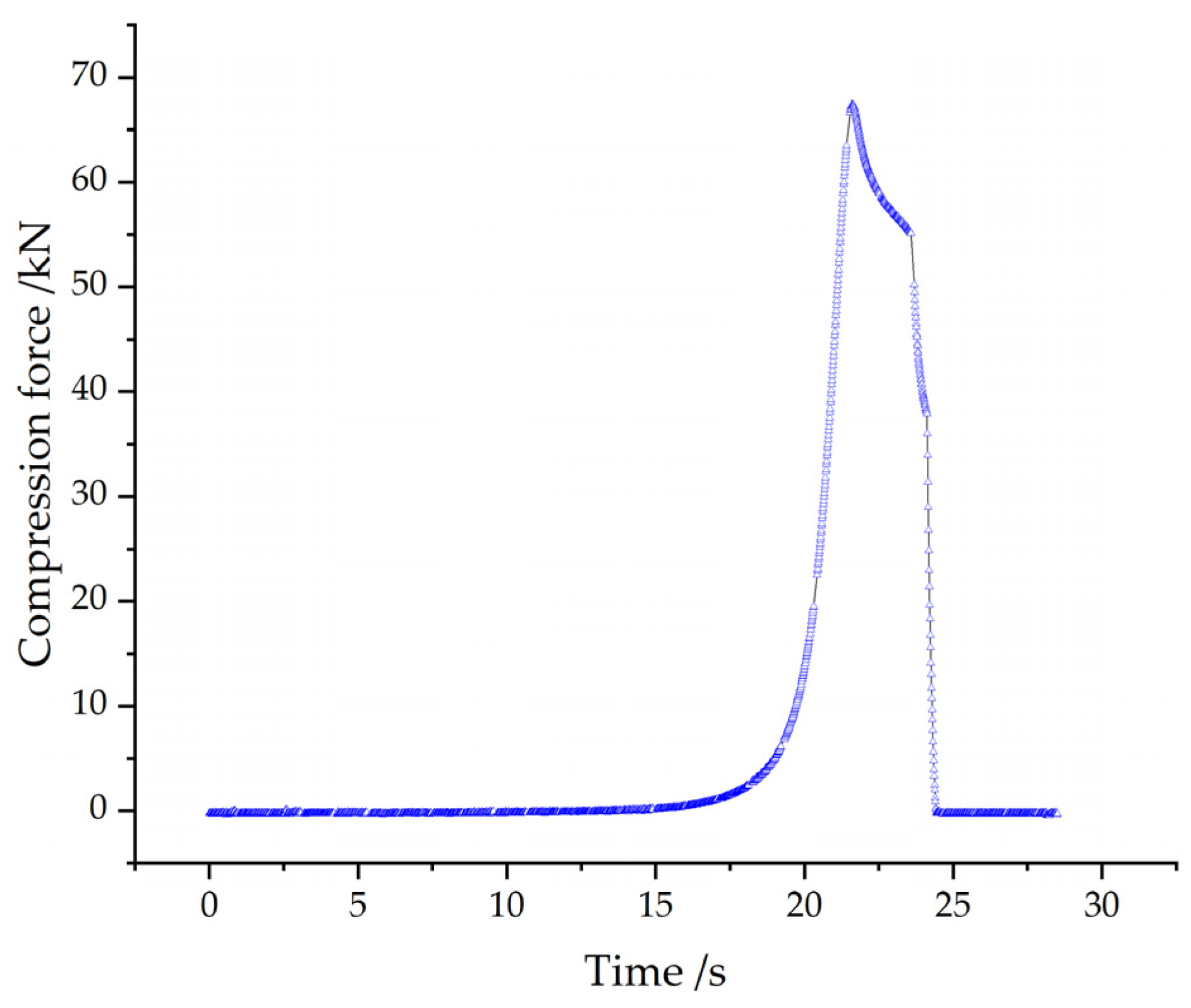
4.1.3. The Relationship between Compression Force and Die Wear

The predominant wear mechanism on the inner wall surface is primarily grinding wear. During the extrusion and sliding of alfalfa blocks, the combined action of extrusion pressure and cutting force leads to plastic deformation and material loss on the inner wall of the die. The depth of wear during alfalfa extrusion, a correlation that we have found to be remarkably precise, aligns closely with the normal extrusion pressure, and the direction of furrows aligns with the extrusion direction. The depth of mold wear is closely related to the extrusion pressure.
The force analysis of the alfalfa briquette inside the mold is shown in Figure 7. In the compression direction, the pressure transmitted P Y by the compression rod and the resistance force P Y i of the rear alfalfa briquette, where P Y i gradually diminishes from the mold edge to the core [31]. Moreover, P Y d Y and P Y i are approximately equal. The closer to the die outlet, the smaller the force transmitted to the alfalfa briquette by the compression rod [32]. Along the radial direction of the mold, the alfalfa block is subjected to the squeezing force N Y and friction force f of the inner wall of the mold, which can be calculated as follows [16]:
P Y = P N λ ( e 2 μ λ y / r 1 )
N Y = P N λ ( e 2 μ λ y / r e 2 μ λ ( y d y ) / r ) / μ
N Y = F N ,
where λ is the Poisson’s ratio of the alfalfa material; μ is the friction coefficient between the material and the die; d y is the calculation the thickness of the alfalfa briquette; PN is the pre-compaction pressure, and the unit is Pa; and FN is the extrusion pressure of the die, and the unit is N.
Based on the Archard wear theory, the pressure variation in the axial direction of the die and the pressure variation in the radial direction decrease gradually as they approach the die outlet. The main wear area is the region where the plunger stops, while the wear at the extrusion die outlet is very small.

4.2. Simulation Experimental Results and Discussion

4.2.1. Setting of DEM Parameters

By comparing the actual experimental compression stage maximum force (66.41 to 72.97 kN) and the numerical simulation compression stage maximum force (69.78 to 71.43 kN), the numerical model simulation results are within the range of the actual experimental results, and the average error is less than 2%. Therefore, the numerical model is consistent with the actual experiment.
By using Formulas (1), (2), (5)–(7), we calculated the wear coefficient values in the EDEM software’s Archard wear model.

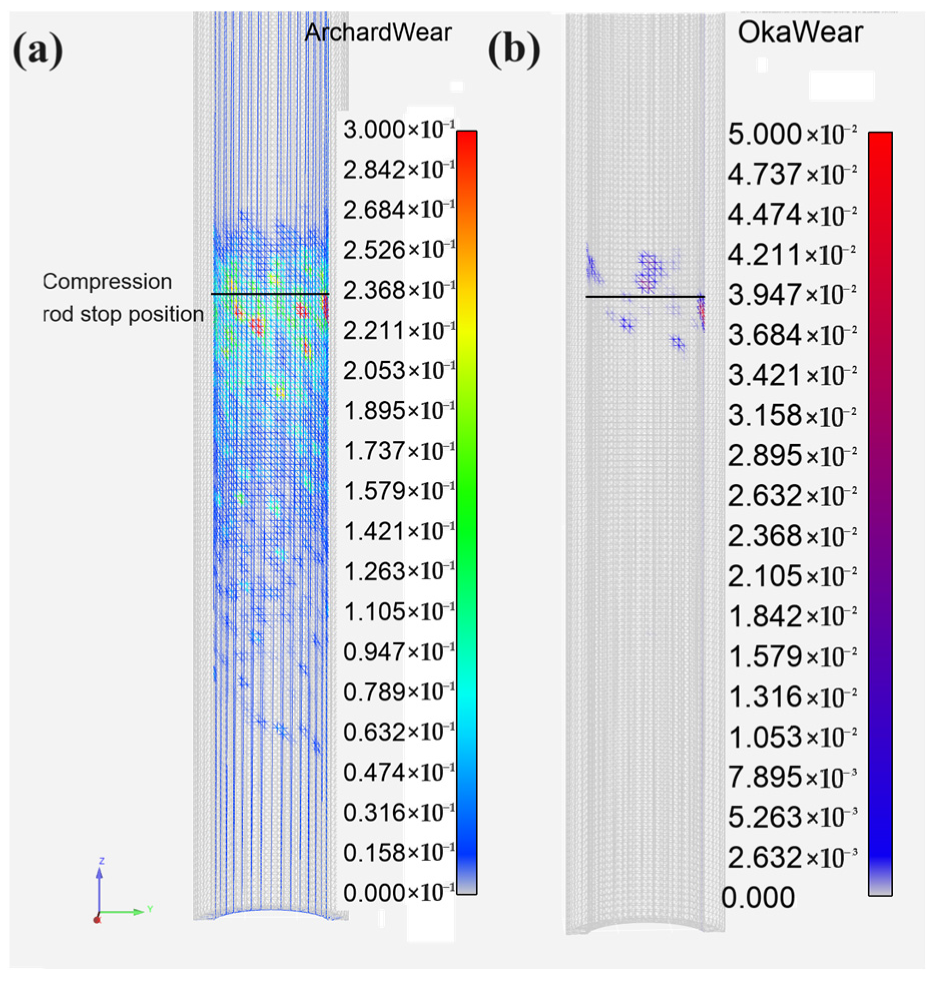
4.2.2. Simulated Test Wear Conditions

According to the actual modeling of the compaction force during the compression-extrusion process, two compressed extrusions were completed. Based on the Archard wear model, the wear distribution of the die is shown in Figure 8a. The severe wear occurs at the compression end of the punch, while the wear near the mold exit is reduced. Deeper grooves and pits are observed in the upper part of the die-forming area. Vertical grooves with relatively shallower depth and pits remain in the middle region, but the wear area and depth have decreased. Near the die exit, only a few fine striations are visible. The simulated analysis results of die wear are consistent with the experimental findings regarding the change trends.
Based on the wear condition shown in Figure 8b of the Oka wear model, during the extrusion process, the impact wear on the inner wall surface of the die caused by the particles is relatively small, with a maximum wear of approximately 0.05 mm. Slight wear only appears in the ram stop area, and no erosion wear is observed in other locations.
Using the Archard wear model, a discrete element simulation of die wear was conducted, with the die outlet as the zero point. The results of the axial wear depth distribution of the mold are shown in Figure 9. Near the compression rod stop position, wear depth nodes below 40 (0.15% of the total) were ignored, i.e., nodes with wear values above 0.145 mm were disregarded. Within the 150~70 mm range, there were 690 nodes with a wear depth of 0.005~0.050 mm, 563 nodes with a wear depth of 0.050~0.100 mm, and 245 nodes with a wear depth of 0.100~0.145 mm. Combining this with the statistical graph of wear depth nodes in Figure 9, it is evident that the wear in this forming area is the most severe, with the majority of high-wear nodes concentrated in the mold feed area and a portion of the forming area. Closer to the die outlet, the wear on the inner die wall gradually decreases. Nodes with a wear depth of less than 0.005 mm account for 82.82% of the total number of nodes.

4.2.3. Stress Transmission and Wear Conditions

The force chain is the contact force transmission path generated by the interaction between particle units and the contact between particles and particle–die under external load and gravity. The force chain distribution diagram is shown in Figure 10a. Red and green represent strong force chains, with red being the highest contact force, while gray represents weak force chains. It can be observed that the force chain strength gradually decreases from top to bottom along the axial direction. However, the force chain distribution is relatively chaotic in the same horizontal radial direction, with strong contacts mainly distributed on the die wall and the compression rod. By selecting the strong contacts formed between the particles and the die wall and observing the schematic diagram of the intense contact and die wear distribution (Figure 10b), it is evident that in the positions where the particles and the die strongly interact, there are distinct wear areas, forming a sharp contrast with the surrounding areas. The wear depth distribution is uneven in the same radial horizontal direction [33]. At these strong contact points, the wear depth of the die is more profound, and as the strong contact points move downward, the high wear volume area extends downward, forming axial stripes. The evolution of the force chain causes other spot areas to have higher wear depth. The evolution of the force chain essentially involves the breakage and disappearance of the original strong force chain and the formation of a new vital force chain [34]. Based on the pressure distribution of the particles on the mold wall in Figure 10b,c, the wear mechanism of the mold surface can be further analyzed; it is established that the force transmission pattern of the particles during the compression process determines the pressure distribution on the die wall.
The schematic diagram in Figure 11 shows the changes in particle compression force, force chain contact normal force, die pressure, and Archard wear model wear depth overtime during the compression process. The variation patterns of compression force, force chain contact normal force, and die pressure at each position are nearly consistent during the two extrusion processes. The cumulative wear depth gradually decreases from position 2 to 8, with the cumulative wear at position 1 being very small and slightly higher than the wear at position 6. The cumulative wear during the second compression is lower than the first, especially at position 2, where the wear is reduced by about 0.017 mm. The wear at positions 7 and 8 is minimal, where the particle compression force, force chain contact, normal force, and die pressure are all relatively low. The cumulative wear depth at positions 2, 3, 4, 5, and 6 continues to increase during the gap between the two compressions, indicating that the stress release process in the compacted alfalfa block also causes mold wear.
The overall wear distribution of the die is shown in Figure 12a. The wear is abnormally severe in the regions above and below the compression rod stop position. Wear conditions in this area are complex, with sliding and force concentration causing plastic deformation fatigue wear. This position is the leading research direction for die wear resistance. Comparing the actual 800 compression experiments with the 40-fold average wear predicted by the discrete element model (as shown in Figure 10b), the error between the two is relatively small, with the expected result being about 20 times the actual wear. When using the Archard wear model for simulation, it cannot consider the impact of changes in material properties during the compression process on friction and wear. For example, the specific lubricating effect of the proteins, fats, and starches released from the material during the actual compression process can reduce the coefficient of friction between the surfaces and thus reduce the wear [35].

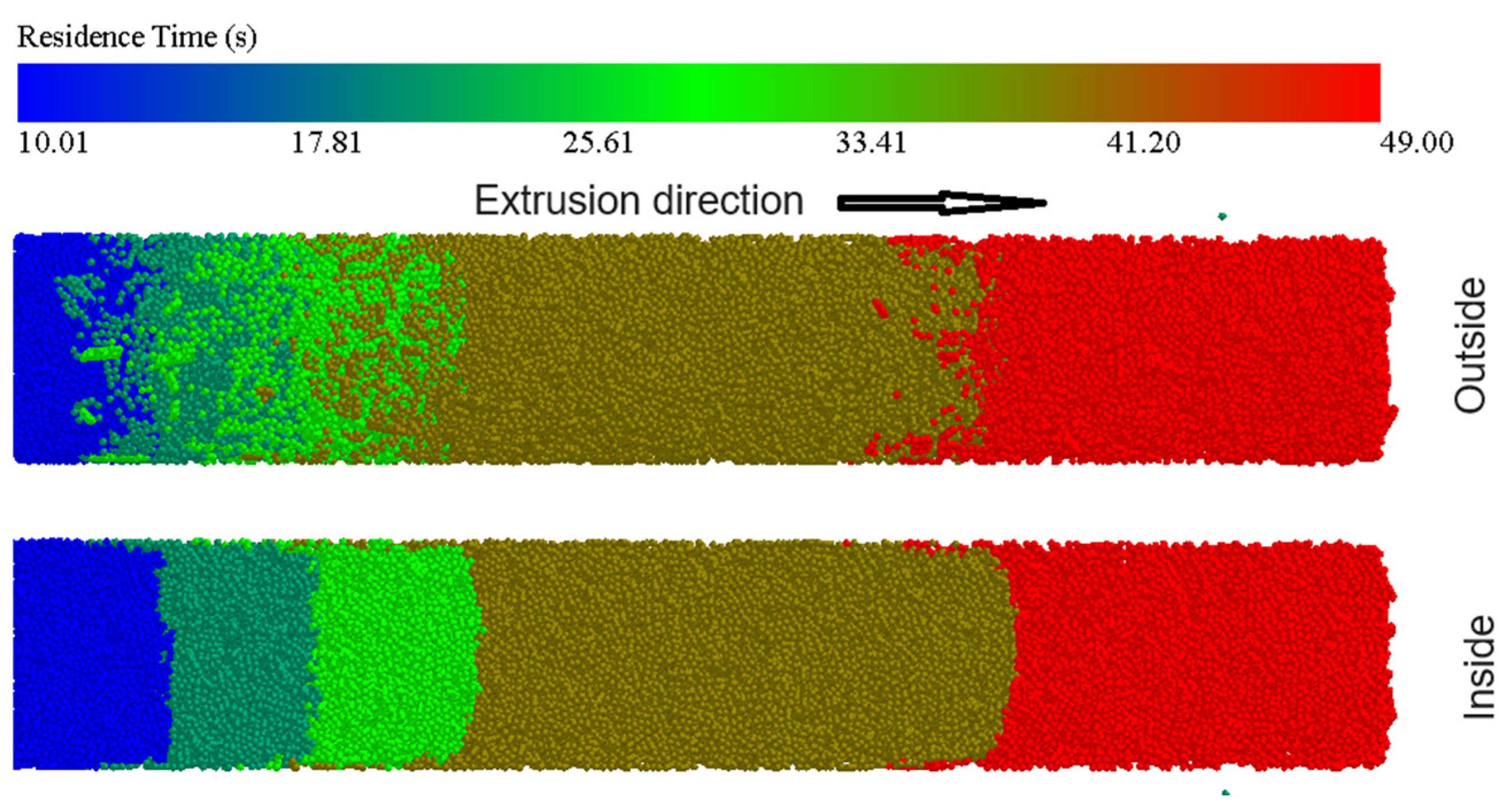
4.2.4. Particle Movement and Wear Conditions

The Oka wear model calculated the wear depth of the particle impact on the inner wall of the die. The main erosion area on the die is within the 140~160 mm mold region (Figure 8), located at the measuring unit positions 1 and 2. Figure 13a shows this location’s particle velocity and impact wear depth–time variation patterns. During the first compression, the maximum particle velocity interval is 48 mm/s, while the maximum velocity during the second compression is 24 mm/s. However, this region has not significantly increased the impact wear depth during the second compression (shown in Figure 13b). The impact velocity and angle significantly influence the impact wear situation, and the material’s mechanical properties can prevent impact wear at lower velocities [36,37]. During the extrusion process of biomass, the biomass particles hardly cause any impact wear on the inner surface of the die.
In reality, the relative displacement between particles can be ignored after the alfalfa blocks are densely formed, and the relative displacement between particles and the mold is the distance of the extrusion movement. Therefore, the average velocity of particle motion during the extrusion stage is close to the compression velocity (5 mm/s). In the numerical discrete element simulation process, particles rush into a limited space, which is inconsistent with the actual situation. The variation in velocity with time (Figure 13) shows that the average velocity value of the particles at position two during the first compression is about 1.772 times that of the second compression, and the cumulative wear amount of Archard Wear during the first compression process is about 1.765 times that of the second compression process. The difference in the cumulative wear amount of Archard Wear between the two compressions is caused by the different displacements of particles (different average velocities) [38].
In numerical calculations, different colors correspond to different feeding frequencies of alfalfa straw, where blue represents the alfalfa straw particles from the last feeding, and red represents the straw particles from the first feeding. Numerical calculations reveal the material distribution pattern inside the mold under different feeding times (Figure 14). During the continuous compression of the material, the displacement distance of the outer layer particles of the alfalfa block in the compression direction is shorter than that of the inner particles, and there is also a certain displacement towards the compression outlet, but slower than the inner particles, indicating that some particles will adhere to the mold wall. The stress distribution pattern (as discussed in Section 4.1.2 of this paper) affects the particle distribution. In practice, the fine particles of the crushed purple alfalfa will adhere to the inner wall of the mold or be compressed into the small micro-depressions and grooves on the mold surface [39]. Alfalfa straw is a viscoelastic material, and under a certain pressure, adhesion occurs between the particles and between the particles and the mold. At this time, the inner particles slide relative to the particles attached to the wall, reducing mold wear to a certain extent. This indicates that this model can only represent the partial wear reduction effect and wear mechanism caused by material adhesion [40]. However, Archard’s wear model cannot incorporate the specific wear mechanism of adhesive wear caused by material adhesion [41].

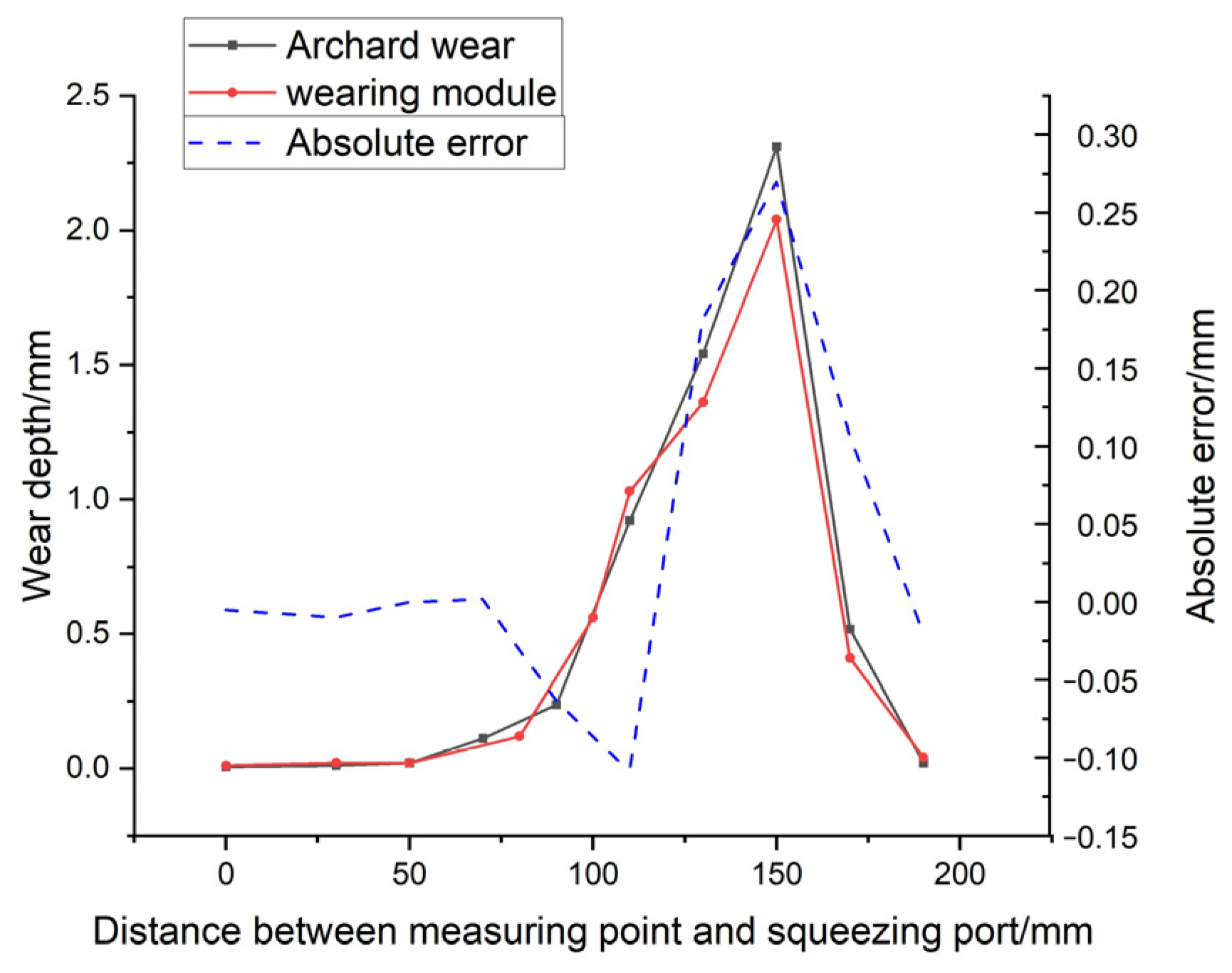
4.3. Simulation Model Validation Results

The particle velocity in the simulated model is significantly higher than the actual situation, and it significantly impacts the prediction results of the discrete element wear model. The close relationship between the simulated wear and particle velocity is demonstrated. Therefore, the ratio e between the simulated particle velocity and the actual particle velocity (5 mm/s) is used as the amplification factor for the particle velocity.
During the extrusion stage of a single particle compaction process, the force chain strength is expected to maintain a horizontal fluctuation with the die pressure, and a slight increase may occur; the compression force in the extrusion process is expected to slowly decrease [28]. However, the findings present a contradiction. The corresponding data generated by the particle counter-evidence compaction process (positions 2, 3, 4) gradually increases, indicating that the particle force on the mold during the extrusion stage of the compaction process is amplified. The ratio t of the average normal contact force Fa during the compression process to the initial normal contact force Fb is the amplification factor of the normal contact force between the particle and the die. When there is no upward rise in the normal contact force during the compression process, the amplification factor is set to 1.
According to the variation law of the contact normal force between the particle motion speed and the force chain at different positions, the corrected predictive value x of the cumulative wear in this region is calculated (Equation (8)). The overall wear distribution of the simulated die is obtained. The comparison chart of the corrected wear prediction and the actual experimental wear (Figure 15) reveals that the corrected predictive value is close to the actual situation, with a relatively small absolute error. The results of the corrected prediction model can effectively and reliably predict the wear condition of the die.
x = A r c h a r d s   w e a r   d e p t h e × t ,

4.4. DEM Analysis

Through the above detailed description and discussion, it was found that the discrete element wear model of the die-cast mold has significant advantages. Compared to the finite element method (FEM) wear model of the die-cast mold, the work of Chen et al. [16] established a simulation model for the die wear based on the finite element method, which can clearly predict the wear depth at different positions of the die in the extrusion direction, similar to the actual situation. However, the wear depth at the same horizontal radial position of the die is not significantly different. The actual die shape after wear failure is not cylindrical but presents various shapes [6], as shown in Figure 16. The discrete element model established in this paper can predict results closer to the actual situation in both the extrusion direction and the radial direction, indicating differences in the wear condition of the die in the radial direction, which is also one of the main reasons for die failure.

5. Conclusions

The study investigated the wear of biomass compaction molds using discrete element modeling and the Archard wear and Oka wear models to simulate and analyze biomass compaction mold wear experiments. The accuracy of the numerical model predictions was verified through experimental results. The main findings can be summarized as follows:
  • The study observed and analyzed the micro-wear of 45 steel. The primary wear mechanisms of the mold were identified as micro-cutting by abrasive particles and high-pressure plastic fatigue wear. By juxtaposing the compression force distribution [9] with the wear depth distribution, it was deduced that significant wear is more likely to occur near the ram’s stopping position. The mold wear depth gradually decreases along the compression extrusion direction, but the wear depth distribution is uneven at the same radial level. These findings provide valuable insights for improving future numerical models.
  • The distribution of force chains exhibits a significant correlation with the pattern of die wear. The interaction between particles and the die generates force chains, which, when sliding relative to the die’s inner wall, induce a micro-cutting effect on the particles. This process facilitates localized wear on the die, ultimately forming characteristic furrows on the inner surface of the die. This phenomenon not only reveals the direct influence of force chain distribution on die wear but also provides crucial insights into understanding wear mechanisms in complex particulate systems.
  • According to the DEM results, the particle shape and size were modeled based on particle morphology. The predicted wear distribution and the force change law during the compaction stage of the densification process were consistent with the experimental results. In actual wear experiments, the adhesion of particles to the die wall plays a unique role in reducing wear, and the discrete element model also characterizes this phenomenon but cannot calculate the amount of wear reduction. During the compression stage, the particles exhibit local active motion, which differs from the actual situation.
  • The current numerical models face a significant challenge in effectively addressing speed anomalies. While the corrected predictive model results can reliably and effectively forecast mold wear conditions by processing and calibrating the data, it is important to acknowledge that more robust numerical models are being developed through parameter optimization and testing to overcome these limitations.
The final discrete element wear model of the forming die is established is able to take into account more complex wear situations and better predict the wear of the forming die. This provides a new method for the wear prediction of a dense biomass forming die.

Author Contributions

Conceptualization, H.D. (Haijun Du) and Y.M.; methodology, H.D. (Haijun Du); software, H.D. (Haijun Du); validation, H.D. (Hailong Du), Y.M. and H.S.; formal analysis, H.D. (Haijun Du), J.X.; investigation, H.D. (Haijun Du) and Y.M.; resources, Y.M.; data curation, H.D. (Haijun Du); writing—original draft preparation, H.D. (Haijun Du); writing—review and editing, H.D. (Haijun Du), Y.M. and H.D. (Hailong Du); visualization, C.X.; supervision, Y.M.; project administration, H.S.; funding acquisition, Y.M. All authors have read and agreed to the published version of the manuscript.

Funding

This research was funded by Interdisciplinary Research Fund of Inner Mongolia Agricultural University (No. BR231517), National Natural Science Foundation of China (No. 32060771), Fundamental Research Funds of Inner Mongolia Agricultural University (Nos. BR221314, BR221032) and Science and Technology Planning Project of Inner Mongolia Autonomous Region (No. 2023YFDZ0037), First Class Disciplines Research Special Project (YLXKZX-NND-009).

Institutional Review Board Statement

Not applicable.

Data Availability Statement

The raw data supporting the conclusions of this article will be made available by the authors on request.

Acknowledgments

The author acknowledges the Inner Mongolia Engineering Research Center of Intelligent equipment for the entire process of forage and feed production.

Conflicts of Interest

The authors declare no conflicts of interest.

References

  1. Demirbas, M.F.; Balat, M.; Balat, H. Potential contribution of biomass to the sustainable energy development. Energy Conv. Manag. 2009, 50, 1746–1760. [Google Scholar] [CrossRef]
  2. Miloš; Matúš, P. K.Ľ.Š. Design of pressing tools for pelleting machines. World J. Adv. Eng. Technol. Sci. 2021, 4, 52–62. [Google Scholar] [CrossRef]
  3. Cutz, L.; Haro, P.; Santana, D.; Johnsson, F. Assessment of biomass energy sources and technologies: The case of Central America. Renew. Sustain. Energy Rev. 2016, 58, 1411–1431. [Google Scholar] [CrossRef]
  4. Song, X.; Zhang, S.; Wu, Y.; Cao, Z. Investigation on the properties of the bio-briquette fuel prepared from hydrothermal pretreated cotton stalk and wood sawdust. Renew. Energy 2020, 151, 184–191. [Google Scholar] [CrossRef]
  5. Vaish, S.; Sharma, N.K.; Kaur, G. A review on various types of densification/briquetting technologies of biomass residues. IOP Conf. Ser. Mater. Sci. Eng. 2022, 1228, 12019. [Google Scholar] [CrossRef]
  6. Jiang, Q.H.; Wu, K.; Sun, Y.; Xia, X. Wear mechanism analysis of ring die of pellet mill. Trans. CSAE 2013, 29, 42–49, (In Chinese with English Abstract). [Google Scholar] [CrossRef]
  7. Orisaleye, J.I.; Ojolo, S.J.; Ajiboye, J.S. Mathematical modelling of die pressure of a screw briquetting machine, Journal of King Saud University. Eng. Sci. 2020, 32, 555–560. [Google Scholar] [CrossRef]
  8. Wang, H.Y. Analysis of Heat and Stress Transfer of Compression with Assisted Vibrationfor Alfalfa Straw Based on Discrete Element Method; Inner Mongolia Agricultural University: Hohhot, China, 2021. [Google Scholar] [CrossRef]
  9. Du, H.J. Multi-Scale Mechanical Analysis and Parameter Optimization of Alfalfa Densification Molding; Inner Mongolia Agricultural University: Hohhot, China, 2023. [Google Scholar] [CrossRef]
  10. Du, H.; Lei, T.; Ma, Y.; Li, Y.; Yang, X.; Du, X. Effect of process parameters on quality of alfalfa block. BioResources 2024, 19, 3234–3248. [Google Scholar] [CrossRef]
  11. Zhang, W.; Zhou, J.; Zhang, X.L.; Zhang, Y.; Liu, K. Quantitative investigation on force chain lengths during high velocity compaction of ferrous powder. Mod. Phys. Lett. B 2019, 33, 1950113. [Google Scholar] [CrossRef]
  12. Wang, X.; Zhao, X. The Application of Ceramic Wear Resistant Materials in Biomass Briquetting Equipment. Energy Environ. 2014, 25, 1003–1009. [Google Scholar] [CrossRef]
  13. Thompson, J. Wear and Impact Analysis of Granular Materials Using Discrete Element Method Simulations. Ph.D. Thesis, Swansea University Prifysgol Abertawe, Swansea, UK, 2023. [Google Scholar] [CrossRef]
  14. Ren, S.; Lil, J.; Shil, Y.; Wen, B.; Lil, L.; Su, Z. Wear characteristics of flat die in flat die pellet mills based on Glycyrrhiza uralensis. Mater. Res. Express 2022, 9, 076510. [Google Scholar] [CrossRef]
  15. Zhou, G.A. Study on the Forming Mechanism of Biomass Molding Machine and Wear Test of Key Components; College of Engineering Hefei: Hefei, China, 2023. [Google Scholar] [CrossRef]
  16. Chen, S.; Ding, H.; Tang, Z.; Hao, S.; Zhao, Y. Influence of rice straw forming factors on ring die wear and improved wear prediction model during briquetting. Biosyst. Eng. 2022, 214, 122–137. [Google Scholar] [CrossRef]
  17. Wen, B.H.; Liu, L.; Liu, S.Y.; Zheng, K.X.; Hua, L.; Wang, S. Analysis and Research of Force and Motion of Screw-Type Extrusion Molding Biomass. Adv. Mater. Res. 2012, 614–615, 452–459. [Google Scholar] [CrossRef]
  18. Argatov, I.I.; Bae, J.W.; Chai, Y.S. A Simple Model for the Wear Accumulation in Partial Slip Hertzian Contact. Int. J. Appl. Mech. 2020, 12, 2050074. [Google Scholar] [CrossRef]
  19. Capozza, R.; Hanley, K.J. A comprehensive model of plastic wear based on the discrete element method. Powder Technol. 2022, 410, 117864. [Google Scholar] [CrossRef]
  20. Sun, H.; Ma, H.; Zhao, Y. DEM investigation on conveying of non-spherical particles in a screw conveyor. Particuology 2022, 65, 17–31. [Google Scholar] [CrossRef]
  21. Yu, H.; Liu, H.; Zhang, S.; Zhang, J.; Han, Z. Research progress on coping strategies for the fluid-solid erosion wear of pipelines. Powder Technol. 2023, 422, 118457. [Google Scholar] [CrossRef]
  22. Du, H.J.; Lei, T.; Zhang, Y.A.; Wu, P.; Ma, Y.H.; Bu, K. Evolution of force chain in vibration compression of alfalfa. Trans. Chin. Soc. Agric. Eng. (Trans. CSAE) 2022, 38, 33–40, (In Chinese with English Abstract). [Google Scholar] [CrossRef]
  23. Zhao, L.; Jin, X.; Liu, X. Numerical research on wear characteristics of drum based on discrete element method (DEM). Eng. Fail. Anal. 2020, 109, 104269. [Google Scholar] [CrossRef]
  24. Xia, X.; Sun, Y.; Wu, K.; Jiang, Q. Wear mechanism of ring die for straw briquetting machine. Trans. CSAE 2014, 30, 32–39, (In Chinese with English Abstract). [Google Scholar] [CrossRef]
  25. Zhang, Z.; Mei, F.; Xiao, P.; Zhao, W.; Zhu, X. Discrete element modelling and simulation parameters calibration for the compacted straw cube. Biosyst. Eng. 2023, 230, 301–312. [Google Scholar] [CrossRef]
  26. Tang, H.; Xu, W.; Zhao, J.; Xu, C.; Wang, J. Comparison of rice straw compression characteristics in vibration mode based on discrete element method. Biosyst. Eng. 2023, 230, 191–204. [Google Scholar] [CrossRef]
  27. Ghatrehsamani, S.; Akbarzadeh, S.; Khonsari, M.M. Application of Continuum Damage Mechanics to Predict Wear in Systems Subjected to Variable Loading. Tribol. Lett. 2021, 69, 163. [Google Scholar] [CrossRef]
  28. Oka, Y.I.; Okamura, K.; Yoshida, T. Practical estimation of erosion damage caused by solid particle impact. Part 1: Effects of impact parameters on a predictive equation. Wear 2005, 259, 95–101. [Google Scholar] [CrossRef]
  29. Wang, H.; Wu, P.; He, H.; Ma, Y.; Bu, K.; Xue, J. Calibration of parameters for discrete element simulation model for alfalfa with different moisture contents based on angle of repose test. BioResources 2022, 17, 1467–1484. [Google Scholar] [CrossRef]
  30. Ma, Y.H.; Song, C.D.; Xuan, C.Z.; Wang, H.Y.; Yang, S.; Wu, P. Parameters calibration of discrete element model for alfalfa straw compression simulation. Trans. Chin. Soc. Agric. Eng. (Trans. CSAE) 2020, 36, 22–30, (In Chinese with English Abstract). [Google Scholar] [CrossRef]
  31. Nielsen, S.K.; Mandø, M. Experimental and numerical investigation of die designs in biomass pelleting and the effect on layer formation in pellets. Biosyst. Eng. 2020, 198, 185–197. [Google Scholar] [CrossRef]
  32. Du, H.J.; Ma, Y.; Lie, T.; Wu, P. Effect of vibrational frequency on alfalfa opening compression process. Bioresources 2022, 17, 6706–6717. [Google Scholar] [CrossRef]
  33. Jiang, Q.H. Study on the Mechanism and Technology of Rotary Extrusion Forming of Feed Poeder. Nabjing University of Science and Technology, Nanjing, China, 2018. Available online: https://xueshu.baidu.com/usercenter/paper/show?paperid=114y0py0b53604e0p9460cw0m1540359 (accessed on 30 July 2024).
  34. Zuo, M.M. Dynamic Characteristics of Solid Granules by Superimposing High Frequency Vibrations. Yanshan University, Qinhuangdao, China, 2018. Available online: https://dzzyfx.imau.edu.cn/piskns.cnki.net/kcms2/article/abstract?v=WdAl4K16JyWTptEZ8UwJM9cefuRjmIvlHChMKjrY5TTKFcg6sXZWUBaUYqU9icy9nejjt1ESdsWT-dBR278SB2Rn3vP-FJfz_F5UuIogJ0o-fbl4pGAR5P_kSDR_zJ-xTzapUBaUrYnbRwAYbib75g==&uniplatform=NZKPT&language=CHS (accessed on 30 July 2024).
  35. Kraus, M.; Lenzen, M.; Merklein, M. Contact pressure-dependent friction characterization by using a single sheet metal compression test. Wear 2021, 476, 203679. [Google Scholar] [CrossRef]
  36. Chung, R.J.; Jiang, J.; Pang, C.; Yu, B.; Eadie, R.; Li, D.Y. Erosion-corrosion behaviour of steels used in slurry pipelines. Wear 2021, 477, 203771. [Google Scholar] [CrossRef]
  37. Zhou, L.; Li, T.; Liu, Z.; Ma, H.; Xu, C.; Dong, Y.; Zhao, Y. An impact energy erosion model with an energy allocation rule for the discrete element method. Wear 2024, 540–541, 205233. [Google Scholar] [CrossRef]
  38. Lindqvist, M.; Evertsson, C.M. Liner wear in jaw crushers. Miner. Eng. 2003, 16, 1–12. [Google Scholar] [CrossRef]
  39. De, X.; Zhang, B.; Guo, W.; Yang, J.; Zhang, J.; Zhai, X. Surface morphology of blended molding pellets made of desert caragana and maize stover. BioResources 2023, 18, 3019–3032. [Google Scholar] [CrossRef]
  40. Pang, H.S.; Yang, Y.X.; Yin, X.; Zhang, B. Experimental and simulation study of a grinding screw surface based on cross-viscosity cellulose. J. Beijing Univ. Chem. Technol. (Nat. Sci.) 2024, 51, 67–75. [Google Scholar] [CrossRef]
  41. Bastola, A.; Stewart, D.; Dini, D. Three-dimensional finite element simulation and experimental validation of sliding wear. Wear 2022, 504–505, 204402. [Google Scholar] [CrossRef]
Figure 1. Schematic diagram of compression test rig.
Agriculture 14 01260 g001
Figure 2. Schematic diagram of the compaction principle.
Agriculture 14 01260 g002
Figure 3. Diagram of particle model.
Agriculture 14 01260 g003
Figure 4. Diagram of die model and distribution position of measuring block.
Agriculture 14 01260 g004
Figure 5. The pressure variation curve of a single compression process.
Agriculture 14 01260 g005
Figure 6. Microscopic image of the inner mold surface. (ac) The rectangular area marks furrows; the oval area marks plastic deformation; Circular area marks dimple; Residual machining marks on rounded rectangular labels.
Agriculture 14 01260 g006
Figure 7. The force analysis of the alfalfa briquette inside the mold.
Agriculture 14 01260 g007
Figure 8. Schematic diagram of simulated model wear depth: (a) the Archard wear model; (b) the Oka wear model.
Agriculture 14 01260 g008
Figure 9. Wear distribution and statistical diagram of nodes on inner wall surface of the die with axial direction. The red rectangle in the image indicates an enlarged local area. The coordinates in the right image are consistent with those in the left, they are not labeled.
Agriculture 14 01260 g009
Figure 10. Relationship between stress evolution distribution, die pressure and wear condition: (a) force chain distribution; (b) schematic diagram comparing the strong contact distribution and wear distribution between particles and die; (c) die pressure distribution diagram. The red circular markings indicate that wear in this area is clearly related to strong contact and pressure. The arrows show that the strong contact in (b) is derived from the force chain distribution in (a). The interacting arrows indicate that the results of the two figures correspond relatively, meaning that the pressure in that area is greater where alfalfa particles have strong contact with alfalfa. The greater the pressure on the mold, the greater the wear.
Agriculture 14 01260 g010
Figure 11. The four values undergo changes over time during the process of dense formation: (a) particle compression force; (b) normal contact force within the force chain; (c) die pressure; and (d) wear depth according to the Archard wear model.
Agriculture 14 01260 g011
Figure 12. Diagram illustrating the distribution of wear depth: (a) simulation depicting a single curve representing changes in compression wear depth; (b) comparative and analytical curve showcasing simulation data versus test data.
Agriculture 14 01260 g012
Figure 13. (a) Particle movement velocity curve with time; (b) Oka wear curve with time.
Agriculture 14 01260 g013
Figure 14. Distribution law of material in the mold at different feeding times.
Agriculture 14 01260 g014
Figure 15. Comparison of predicted and actual experimental wear amounts after calibration.
Agriculture 14 01260 g015
Figure 16. Schematic diagram of wear-induced failure of mold inner cavity shape.
Agriculture 14 01260 g016
Table 1. The discrete element simulation parameter.
ParametersUnitValueSource
Alfalfa
Poisson’s ratio_0.35[9,30]
Solid densitykg/m31000[9,30]
Young’s modulusMPa22.6[9,30]
Steel
Poisson’s ratio_0.3[29]
Solid densitykg/m37800[29]
Young’s modulusGPa70[29]
Alfalfa–alfalfa
Coefficient of restitution_0.11[29]
Coefficient of static friction_0.47[29]
Coefficient of rolling friction_0.23[29]
Alfalfa–steel
Coefficient of restitution_0.16[29]
Coefficient of static friction_0.8[29]
Coefficient of rolling friction_0.225[29]
EEPA
Surface energyJ/m29.5[9,29]
Contact plasticity ratio_0.8[9,29,30]
Tensile exp_1.5[9,29,30]
Tangential stiff multiplier_0.667[9,29,30]
Slope exo_1.5[9,29,30]
Pull-off forceN0[29,30]
Disclaimer/Publisher’s Note: The statements, opinions and data contained in all publications are solely those of the individual author(s) and contributor(s) and not of MDPI and/or the editor(s). MDPI and/or the editor(s) disclaim responsibility for any injury to people or property resulting from any ideas, methods, instructions or products referred to in the content.

