2.2.1. Robotic Hand Size Determination
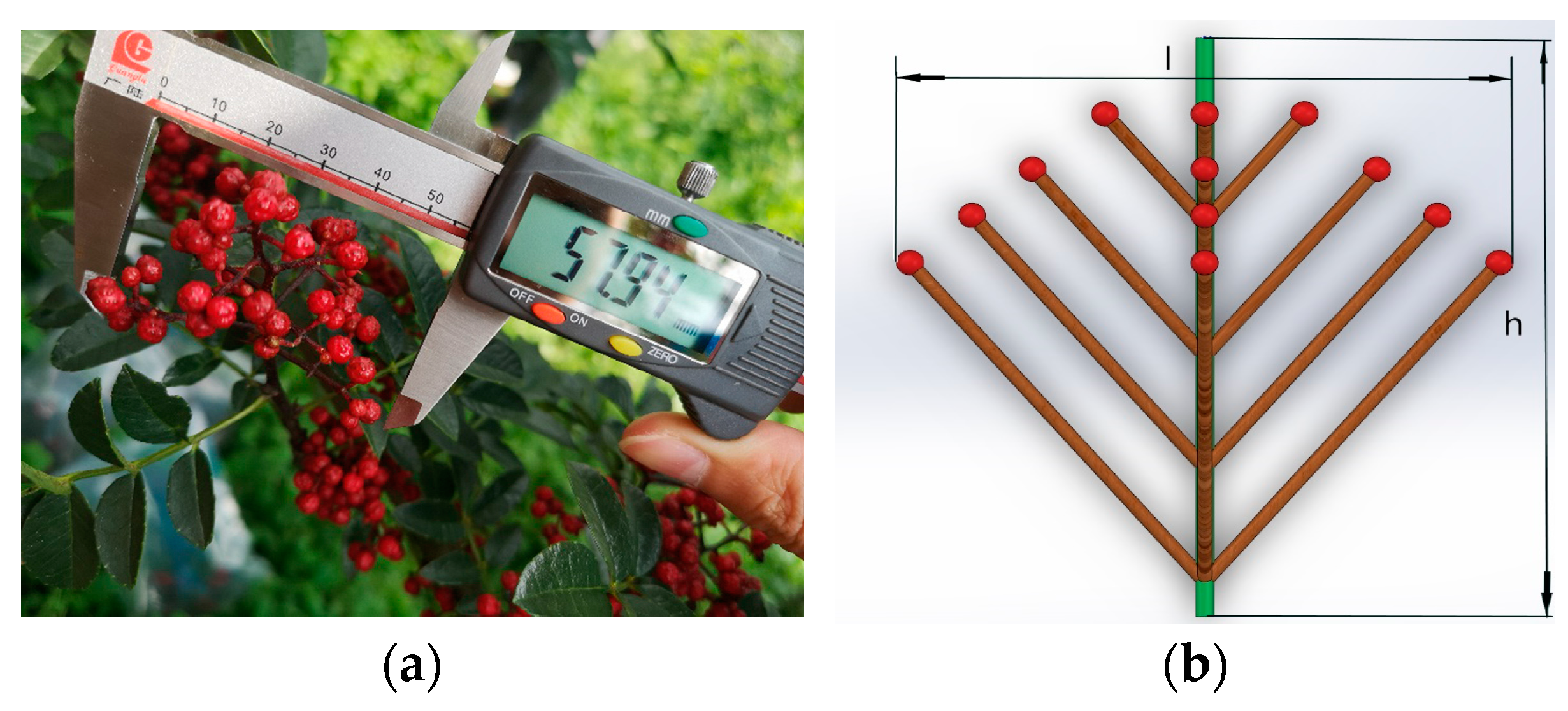
To ensure that the robotic hand can fully grasp clusters of Sichuan pepper without damaging the oil vesicles, the mechanical hand’s finger joint length, palm length, and airbag bending angle need to be designed based on the three-dimensional dimensions of Sichuan pepper clusters. Field experiments cannot measure the dimensions of all Sichuan pepper clusters, and the maximum size of the Sichuan pepper clusters is unknown. However, the stems of Sichuan pepper are elastic, and when the clusters are subjected to pressure from the mechanical hand, they tend to contract inward. The larger the Sichuan pepper cluster, the greater the space available for contraction. Therefore, the dimensions of larger Sichuan pepper clusters can be used as a reference for designing the dimensions of the mechanical hand. After measuring Sichuan pepper clusters with stems of various thicknesses and at different heights, as illustrated in
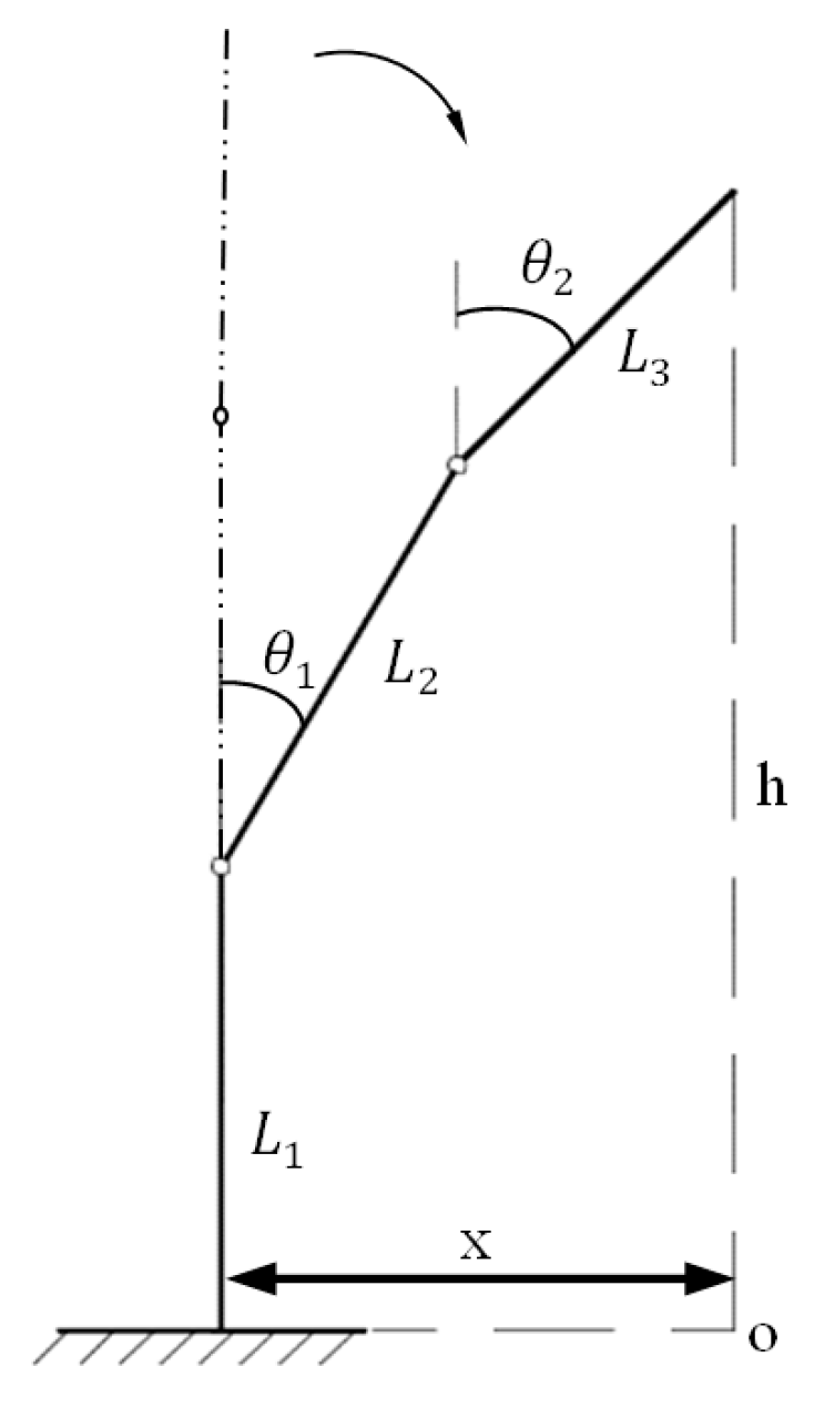
Figure 2, the maximum width of the peppercorn clusters was found to be l =57.94 mm, with a length of h =54.66 mm. A simplified diagram of finger inflation movement is depicted in
Figure 3.
The following was derived from the schematic of finger movement:
where h—Length of fingers from palm;
x—The length of the front end of the finger from the knuckle 1 during bending;
L1—Length of joint 1;
L2—Length of joint 2;
L3—Length of joint 3;
θ1—The first airbag bending angle;
θ2—The second airbag bending angle.
Through MATLAB program calculations, the lengths of joint 1, joint 2, and joint 3 were determined as follows: L1 = 28 mm, L2 = 25 mm, and L3 = 27 mm. Additionally, the first airbag bending angle is θ1 = 51°, and the second airbag bending angle is θ2 = 39°.
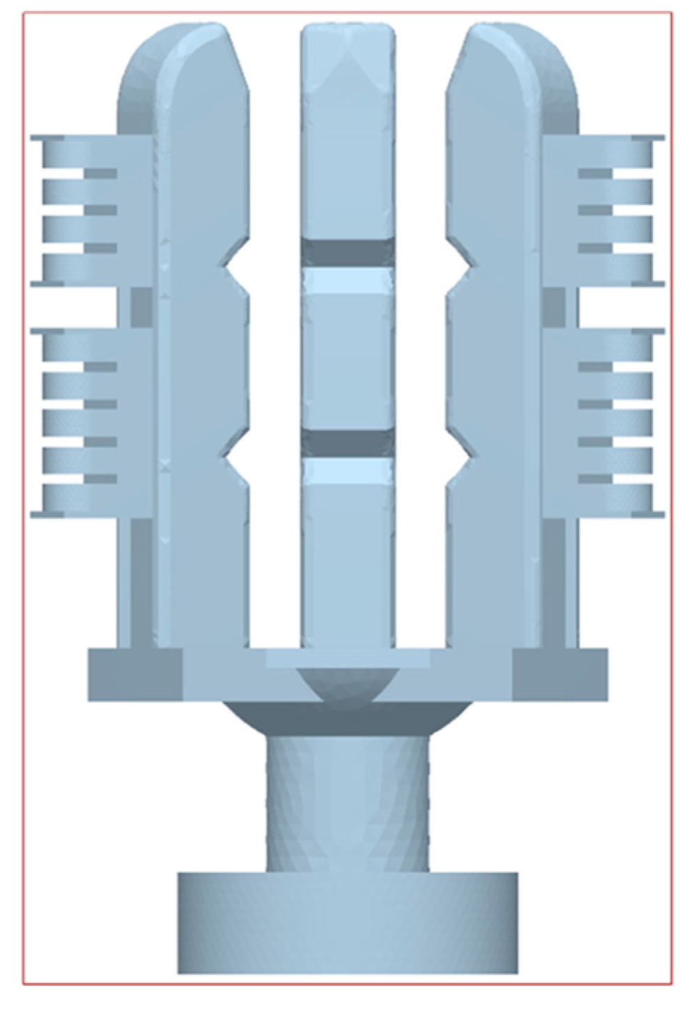
2.2.2. Determining the Structural Parameters of the Joint Airbags
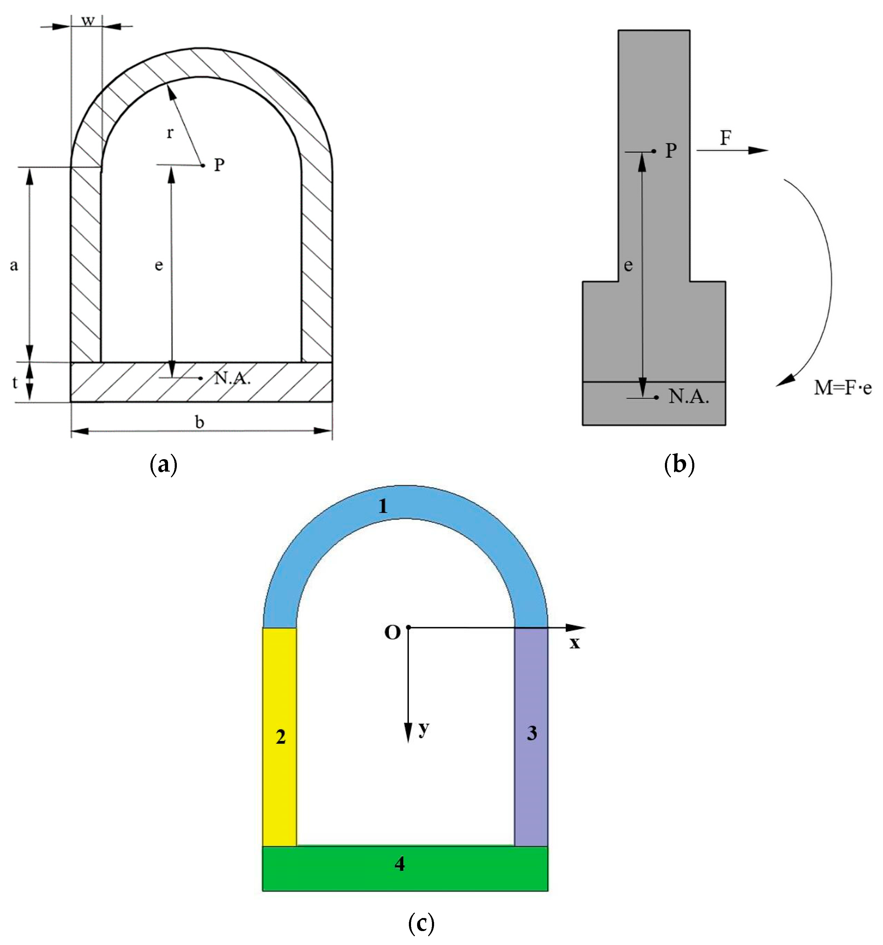
When the joint airbags are inflated and operational, they can be viewed as cantilever beams, subjected only to bending moments.
Figure 4a shows the cross-section of the airbag, where r, w, a, and t, respectively, represent the inner radius, chamber wall thickness, internal dimensions, and bottom thickness. If the cross-sectional area of the chamber is regular, such as circular, spherical, or rectangular, the neutral axis will pass through the centroid of the pressure, and the airbag will expand uniformly in all directions without bending. However, if there is a slight offset between the pressure centroid and the neutral axis, the actuator will bend toward the side where the neutral axis is located. The torque causing this bending is simply the tension force F multiplied by the offset “e” between the pressure centroid and the neutral axis, as shown in
Figure 4b.
The formula for the radius of curvature is
where ρ—radius of the curvature of the airbag;
P—inflation pressure;
A—cross-sectional area inside the channel;
E—modulus of elasticity of the airbag material;
I—cross-sectional moment of inertia.
The bending angle of the airbag is determined by the following equation:
where L—total length of airbag.
In this study, L, P, A, and E remain constant. Therefore, the bending angle θ is mainly influenced by the ratio e/I.
To calculate the offset e between the center of pressure and the neutral axis, find the center of pressure and the neutral axis. The calculation formula is based on the pressure center coordinates:
Since the pressure is constant, the pressure function
p is a constant
p. From
Figure 4a, we can obtain the range of x and y as x∈[−r,r] and y∈[− √(r2 − x2),a], with
The calculated coordinates of the pressure center are [xp, yp] = [0].
The calculation formula of the central axis is
From the calculated centroid coordinates and formula (5), the offset e is obtained as
Divide the cross-section into four parts, a ring and three rectangles, and calculate the centroid coordinates, respectively; thus, we obtain
The moment of inertia I of the cross-section is calculated as follows:
where y—the distance from element dA to the z-axis.
Since the airbag cross-section is a combined cross-section, to calculate the moment of inertia of the combined cross-section on the z-axis, the first step is to calculate the moment of inertia of each component on that axis, and the parallel axis theorem can be used for the calculation. From the parallel axis theorem, we obtain
where I
Z—The moment of inertia of the cross-section about the z-axis;
IZ0—The moment of inertia of the cross-section about its own centroidal axis z0;
D—The distance between the two axes.
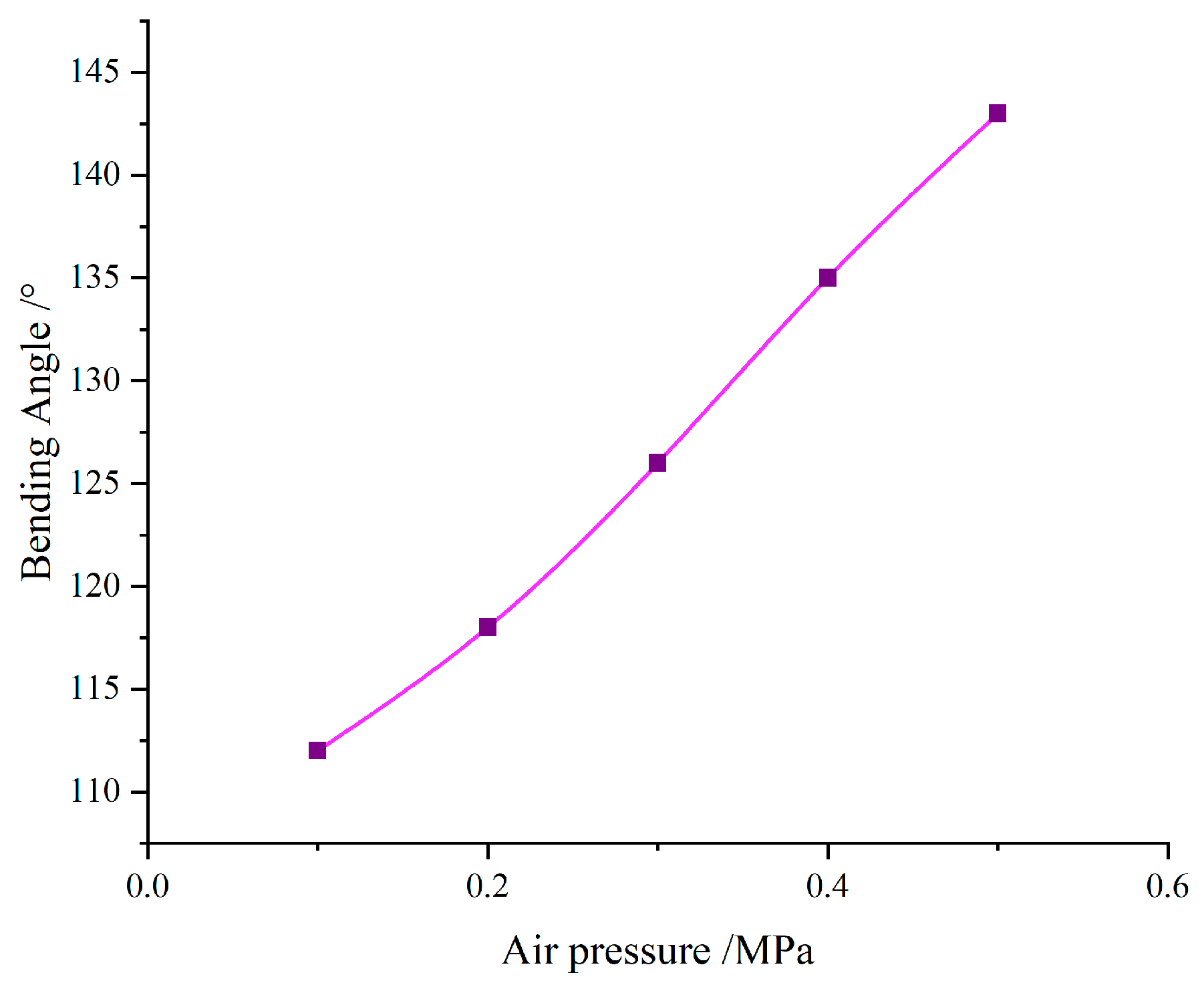
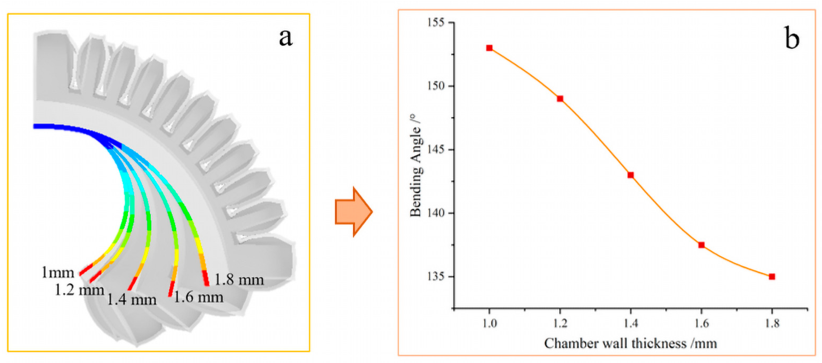
From Equations (7) and (10), it can be seen that the chamber wall thickness and bottom thickness will affect the ratio e/I, which also implies that they will affect the bending angle of the airbag. In this study, the chamber wall thickness variation range is 1 mm ≤ w ≤ 1.8 mm, and the bottom layer thickness variation range is 3 mm ≤ t ≤ 7 mm [
28]. When studying the effect of the chamber wall thickness on the bending angle, the thickness of the bottom layer remains unchanged, and the increment of the chamber wall thickness is 0.2 mm. The offset e between the pressure center and the neutral axis and the cross-sectional moment of inertia I is calculated; similarly, when considering the effect of the bottom layer thickness on the bending angle, the chamber wall thickness remains unchanged, and the bottom layer thickness increment is 1 mm, and the offset e and cross-sectional moment of inertia I are calculated. The results are shown in
Figure 5: As the wall thickness increases, the e/I ratio becomes smaller and the bending angle becomes smaller; as the bottom layer thickness increases, the e/I ratio first increases and then decreases, and the bending angle also increases with the bottom layer thickness. The thickness increases first and then decreases.
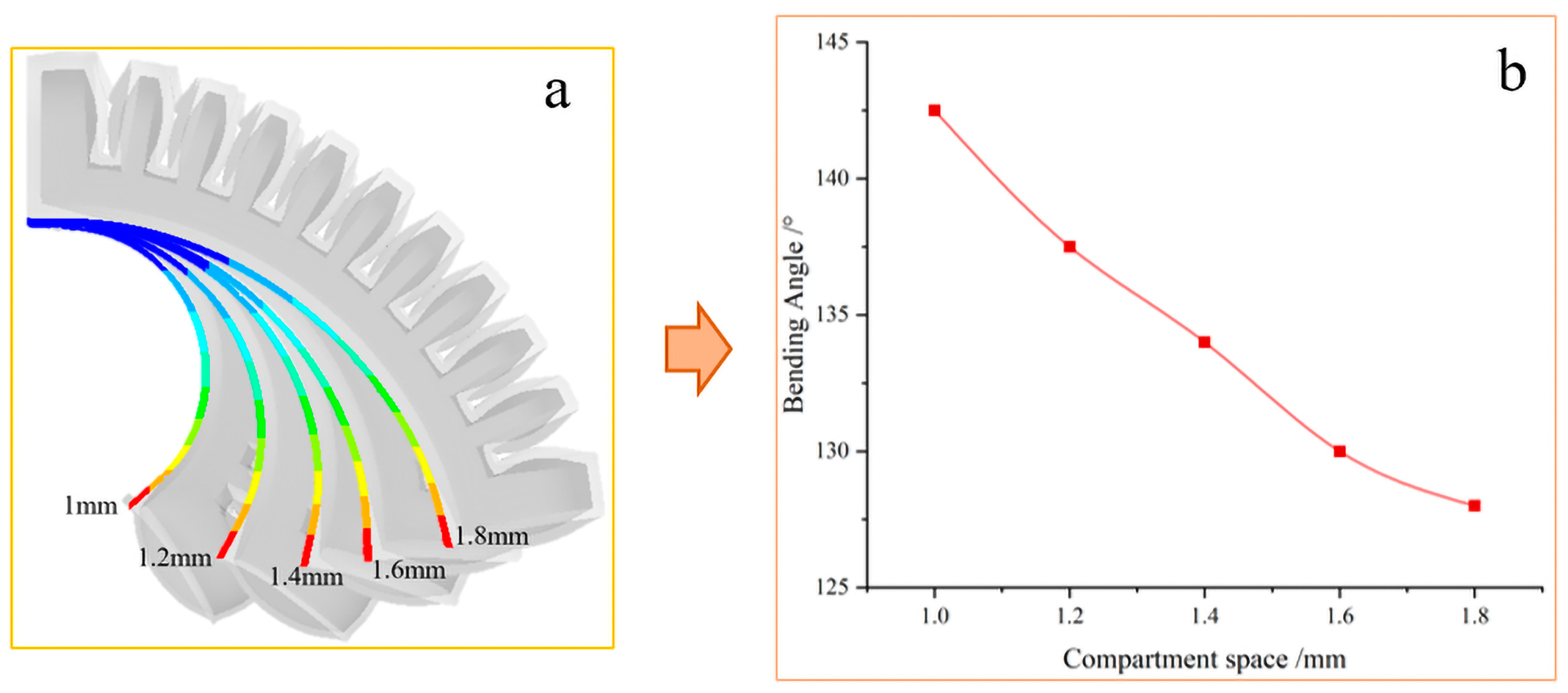
Chamber clearance, that is, the gaps that exist between different chambers in the airbag, has a certain influence under the action of external pressure [
28]. When the airbag is subjected to external pressure, the existing gaps may cause an uneven distribution of gas in the chamber, thereby affecting the overall stability and bending angle of the airbag. This is because the gap may cause the gas to not be transferred evenly when stressed, causing the airbag to produce inconsistent stress distribution when it bends. This uneven distribution may lead to instability of the local structure of the airbag, thereby affecting the overall shape change.


