Abstract
Stem mustard, the main raw material for pickled mustard tuber, is widely planted in Chongqing, China, and is an important local cash crop. Under the working conditions of sticky and wet soil in the Chongqing area, conventional furrow seeding has problems such as soil sticking to the furrow opener, poor mulching effect, etc. In this regard, this paper proposes the use of non-contact, soil-based, pneumatic shot seeding, in which seeds are shot into the soil to a predetermined depth by a high-speed air stream. The diameter of stem mustard seeds was found to be 1.33 mm, with a spherical rate of 95.32% using physical and mechanical properties. The high-speed camera test was used to determine the air pressure at the appropriate sowing depth, and the seed entry process was simulated by EDEM 2021 software, which analysed the movement process of the seed after entering the soil, and the structure of the seeder was designed based on the resulting test data. The structural parameters of the shot seeding device were analysed by a hydrodynamic simulation using Fluent 2022 R1 software and the following results were obtained: an outlet pipe diameter DC of 2 mm, mixing zone length H of 10 mm, mixing zone inlet diameter D of 15 mm, and steady-state gas flow rate of 80 m/s. Simulation seeding verification was conducted on the final determined structural parameters of the seeding device, and the simulation results showed that the seed velocity could reach 32.3 m/s. In actual experiments, it was found that when the vertical velocity of the seeds was greater than or equal to 26.59 m/s, the seeds could be completely and stably seeded into the soil. Therefore, the designed seeding device can meet the conditions of actual seeding experiments. In conclusion, this research offers a practical guideline for the rapid and precise sowing of stem mustard.
1. Introduction
Stem mustard, an important vegetable of the Brassica juncea commonly eaten raw and processed, is the raw material for the production of pickled mustard tuber. In China, the origin of stem mustard is in Chongqing, which is also the largest production area of stem mustard. The area of planting stem mustard in China has exceeded 200,000 hectares, with over half of the planting area mainly concentrated in 13 districts and counties in Chongqing, including Fuling, Wulong, Wanzhou, and other areas. The pickled vegetable industry in Chongqing, with Fuling as its core and radiating to other districts and counties along the Yangtze River, has a total planting area of over 120,000 hectares, an annual output of over 3,200,000 tons, and annual production and sales of over 700,000 tons of finished pickled vegetables, accounting for 70% of China’s urban and rural markets. It has a comprehensive output value of CNY 9.5 billion [1,2,3].
At present, the traditional contact method for growing small-grained vegetables such as stem mustard in China has the disadvantage of high labour intensity, resulting in seed wastage, low efficiency, and poor sowing quality, and even the need to carry out late operations [4,5]. By using no-tillage sowing, the distance and depth of seed sowing can be controlled without touching the soil, avoiding problems such as adhesion, blockage, operational resistance, and power consumption caused by the contact between the machinery and moist soil, and improving the efficiency and accuracy of planting. In addition, no-tillage sowing can reduce soil pollution and the spread of pests and diseases caused by manual operations, which helps to achieve green planting. Therefore, the no-tillage sowing method is of great significance as it can improve the quality and yield of planting and bring more economic and environmental benefits to agricultural production [6,7,8].
The ED series of precision seeding equipment developed by Amazone uses air-aspirated single-particle seeding technology with unique design advantages to ensure that the seeds are not affected by other structures during their free-fall movement and to achieve high-precision seed dropping [9].
Li Fengli et al. [10] analysed the influence of the seeding method and adsorption state on sowing spacing by establishing a mathematical model. A CFD-DEM unidirectional coupled simulation model based on a gas–solid two-phase flow mathematical model to simulate the seeding process of a wheat airflow-assisted linear seeding device. Dong Jianxin et al. [11] proposed a method to constrain the degree of freedom of seed movement and guide the direction of maize seeding, addressing the issues of inconsistent point positions and uneven seed spacing during maize seeding. Ye Yan et al. [12] conducted a theoretical analysis of the seed drop process and determined the optimal structural parameters of the seeder for the community seeder. Evgeny Zykin et al. [13] analysed the sowing process in the ploughing bin and statistically processed the resulting data to derive the corresponding equations. Li Zepei et al. [14] used an EDEM simulation to analyse the casting of single seeds so that the seed drop can be precisely controlled, and optimised the seeding performance of an air-aspirated drum peanut seeder by means of a kinetic modelling approach [15]. Li Yuhuan et al. [16] analysed the seeding performance of an air suction corn high-speed precision seeder, used high-speed camera technology to analyse the seeding process, and optimised the structure. Koller AA et al. [17] conducted research on the issue of targeted maize cultivation. They used 3D laser scanning on corn to obtain its three-axis dimension data. Subsequently, they analysed the stable and reversal points of corn and effectively improved the randomness of the falling direction of corn seeds by adjusting the position of the belt teeth, making planting more accurate. The current research on pneumatic precision sowing mainly focuses on seeds with large particle sizes, and most of the seeds need to be furrowed for pneumatic shot seeding. For small-sized seeds such as stem mustard seeds, pneumatic seeding can be used for precision sowing, and due to the small size of the seeds themselves, the sowing depth is shallow, and no-tillage sowing can be achieved by pneumatic seeding at the same time.
In this paper, a dual-row pneumatic injection seeding device is proposed to solve the problem of the seeding efficiency of stem mustard seeds in a sticky and wet soil environment. The study commenced with a bench test of shot seeding of stem mustard seeds, which was conducted to verify the actual effects and conditions required for the pneumatic seeding of seeds at a shot seeding angle of 60°. Subsequently, the shot seeding situation was analysed by a one-way test utilising EDEM and Fluent software, respectively. The simulation was then compared with the actual test data to determine the optimal parameters of the proposed device.
2. Materials and Methods
We take the seeds of the main variety of stem mustard in Chongqing, “Fuza 2” as the research object [18]. This variety currently occupies a dominant position in the cultivation of Fuling pickled cabbage raw materials. For other types of stem mustard seeds such as “Fuza 5”, the study in this paper is equally applicable. A random selection of 100 undamaged stem mustard seeds were used for experimental measurement, and 5 sets of repeated measurements were conducted. The equivalent diameter and sphericity of stem mustard seeds were defined according to Equations (1) and (2), respectively.
The triaxial size and sphericity of stem mustard seeds were measured through experiments, as shown in Table 1. is the equivalent diameter, are the length, width, and thickness of the seed, is the sphericity.

Table 1.
Triaxial dimensions of stem mustard seeds.
2.1. Principles and Design of the Dual-Row Pneumatic Injection Seeding Device
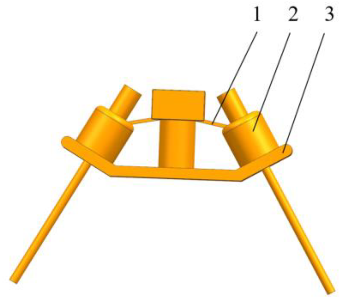
Based on the triaxial dimensions of stem mustard seeds, the device design was carried out under the condition of successful shot seeding of stem mustard shot seeding. The device consists of seed feeding pipes, shot seeders, and shot seeding frame (as shown in Figure 1). Two shot seeders with a horizontal angle of 60° can be installed on the shot seeding frame at the same time, which can realise two rows of simultaneous seeding. Due to the symmetrical installation of the two seeders, their intake and seeding conditions are almost identical. Therefore, this article selects one side of the seeder for analysis.

Figure 1.
Dual-row pneumatic injection seeding device (1. seed feeding pipe; 2. shot seeder; 3. shot seeding frame).
To ensure that the seed grains were smoothly sucked into the seed inlet, the seed pipe diameter of 5 mm was selected. Under the work of the precision seed discharger, the seeds form a single grain flowing into the seed inlet tube, and through the action of negative pressure at the inlet, they are smoothly sucked into the shot seeder. The shot seeding frame had an inclined platform at both ends with a horizontal angle of 60° and 8 mm through holes for mounting the shot seeder. The length of the acceleration pipe H1 should sufficiently mix the seed grains and the high-velocity airflow and maintain a stable acceleration of the seed grains. Therefore, an acceleration pipe length of 200 mm was selected for this study. In addition, because the inlet of the air intake pipe needs to be connected to a standard pressure-resistant pneumatic hose, the diameter of the air intake pipe should be the same as the inner diameter of the hose, which is 12 mm. Since one high-pressure blower produces a high-speed airflow sufficient to perform the job of two jet seeders, the high-pressure airflow can be split into two bundles and supplied to each of the two shot seeders through the use of a one-to-two air hose.
As the core component of the dual-row pneumatic injection seeding device (as shown in Figure 2), the high-pressure gas enters into the inner part of the shot seeder through the air inlet, then enters into the mixing area through the air outlet pipe, and finally realises the rapid shot seeding of seeds into the soil under the action of the high-speed airflow. In operation, the external compressed high-pressure gas is used as the working fluid to realise precise seed sowing, the device introduces air through the air inlet and creates a high-speed airflow from the air outlet pipe. The airflow at the outlet creates a negative pressure in the internal chamber, which is steadily accelerated in the mixing zone to form a positive-pressure accelerated airflow. In this process, the seeds are attracted to the inlet and quickly inhaled, along with the highspeed airflow into the acceleration pipe. Inside the acceleration pipe, the seeds are fully mixed with the positive-pressure accelerated airflow and accelerated, and finally ejected from the lower end of the acceleration pipe at a high speed to hit the soil. In the acceleration pipe, the seeds are mixed with the positive pressure acceleration airflow and accelerated. In the accelerating pipe, the seeds will experience friction and collide with the pipe wall and lose energy, so it is necessary to reduce this energy loss. To achieve this, the diameter of the accelerating pipe D1 is increased, but increasing the diameter leads to expansion of the gas volume [19], which reduces the flow rate of the high-velocity accelerating gas stream [20], which is unfavourable to the acceleration of the stem mustard seeds. Therefore, the diameter of the accelerating pipe should be as small as possible according to the single seed flow. In this study, an accelerating pipe with a diameter of 5 mm was chosen.
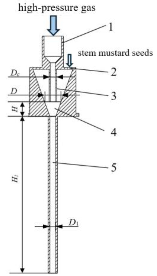
Figure 2.
Sectional view of the shot seeder (1. air intake pipe; 2. seed inlet; 3. outlet pipe; 4. mixing zone; 5. accelerator pipe; D: mixing zone inlet diameter; D1: accelerator pipe diameter; DC: outlet pipe diameter; H: mixing zone length; H1: accelerator pipe length).
2.2. Mechanical Analysis of the Broadcasting Process
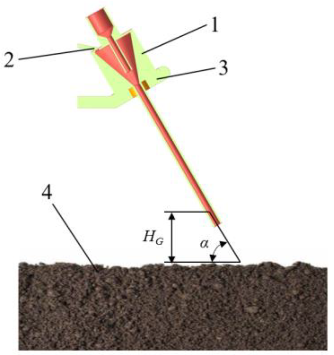
When pneumatic shot seeding sowing takes place, the high-pressure gas inputted through the air compressor is ejected from the outlet pipe to form a stable high-speed airflow, which moves inside the accelerating pipe. The high-pressure gas is ejected at the air outlet, forming a high-speed airflow and creating negative air pressure inside the shot seeder. Stem mustard seed grains are sucked in under the negative pressure and mixed with the high-speed airflow, accelerated inside the accelerating pipe, and then shot out; they are shot into the soil with a certain shot seeding speed and angle of incidence α (60°). The seed particles are sucked in under negative pressure and mixed with the high-speed airflow, as shown in Figure 3.

Figure 3.
Structure of pneumatic seeding test device (HG is the vertical height, (mm); α is the angle of incidence, (°); 1. shot seeder; 2. seed inlet; 3. shot seeding stand; 4. Soil).
In the shot seeder, the flow field uniformity in the mixing zone is poor and not conducive to the stable acceleration of the stem mustard seeds; the pneumatic acceleration process of the stem mustard seeds is mainly realised in the accelerating pipe, which is mainly in the accelerating pipeline of the shot seeding device to complete the acceleration of the stem mustard seeds.
In the stem mustard pneumatic injection seeding device, the seed grain of stem mustard is rapidly accelerated by the thrust of the positive pressure accelerating airflow. After a period of time, the displacement of the seed grain is l m. The force analysis is shown in Figure 4.
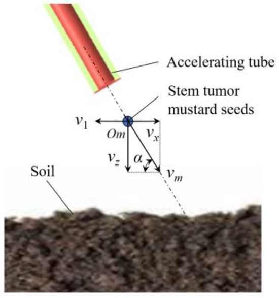
Figure 4.
Analysis of seed movement during actual operation (v1—machine operating speed, m/s; vx—horizontal component of the shot seeding speed, m/s; vz—vertical component of shot seeding velocity, m/s; vm—seeding velocity, m/s; Om—centre of mass of the stem mustard seed grain).
Its acceleration equation can be expressed as follows:
where Rm is the pneumatic thrust, N; dm is the equivalent diameter of stem mustard seed grain, taken as 2 × 10⁻³ m; ρm is the density of stem mustard seed grain, taken as 1122 kg/m3; vm is the speed of stem mustard seed grain, m/s.
The pneumatic thrust is calculated as follows:
where C is the resistance coefficient of stem mustard seed grain, taken as 0.44; ρg is the air density according to 20 °C atmospheric pressure, taken as 1.2 kg/m3; vg is the positive-pressure accelerated air velocity, m/s.
Solving Equations (1) and (2), the differential equations of motion characteristic of the aerodynamic acceleration of stem mustard seed grain in a positive pressure accelerating airflow are as follows:
According to Equations (1)–(3), the acceleration of stem mustard seeds is positively correlated with the positive pressure acceleration airflow vm velocity. The greater the positive pressure acceleration airflow velocity, the more beneficial it will be for the aerodynamic acceleration of stem mustard seeds. As pointed out in the previous analysis, the key structural parameters affecting the internal flow field of the pneumatic stem mustard accurate seed delivery device are the diameter of the outlet pipe, the distance of the mixing zone, and the diameter of the inlet of the mixing zone.
2.3. Pneumatic Injection Seeding Bench Test
The air compressor is used to provide high-speed airflow for the seeds to realise the effect of pneumatic injection seeding, and the relevant parameters are configured as shown in Table 2. The high-speed camera used was a product of Vision Research, Inc., a U.S. manufacturer of high-speed cameras, the specifications of which are shown in Table 3.
Table 2.
Air compressor parameters.
Table 3.
High-speed camera observation schematic.
A soil trough of 200 × 200 × 100 (mm3) was made using a transparent acrylic sheet, and the sampled clay-wet soil was placed into the soil trough with a soil thickness of about 50 mm, soil moisture content: According to the specification GB7172-1987NY/T 52-1987—Method for the determination of soil water content [21], the moisture content of the soil mass is obtained by drying at 105 °C in a drying oven, then weighing and calculating the moisture content of the soil, which is about 30%, and soil compactness of about 1500 kg/m3. Due to the limitations of the test conditions, it was not possible to make adjustments for environmental factors such as soil conditions, so the soil conditions were set to be more severe to ensure that the effects of shot seeding could be met in most soil environments.
Because the colour of stem mustard seeds is similar to the colour of sampled soil, they are not easy to find after falling into the soil, so a physical dyeing method was used to physically stain the stem mustard seeds; the dye used was lemon yellow acrylic pigment.
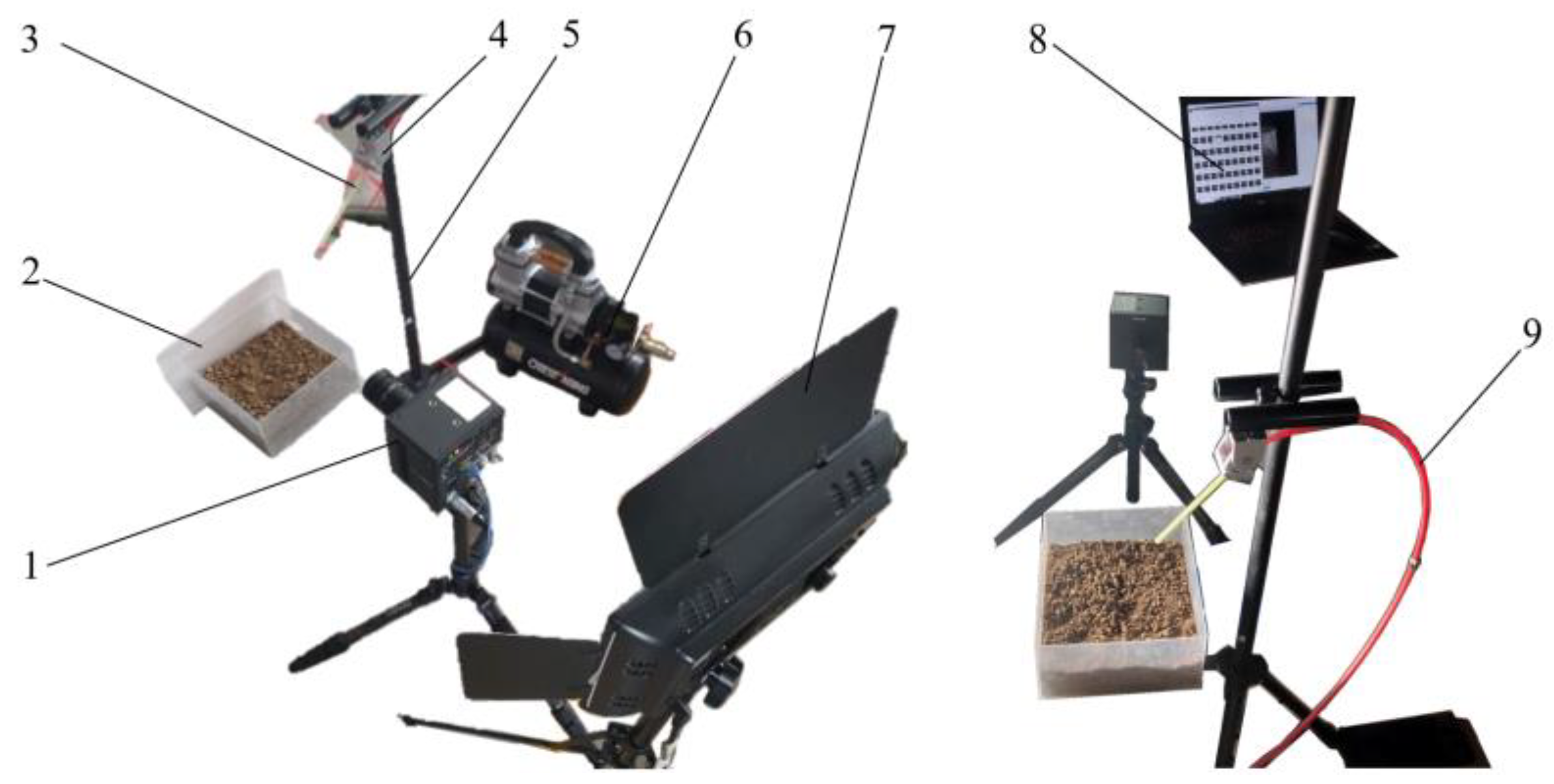
This experiment was carried out using a homemade stem mustard aerial seeding test bed, as shown in Figure 5, which mainly includes a tripod, aerial seeding conduit, pressure-resistant air pipe, air compressor, and computer.
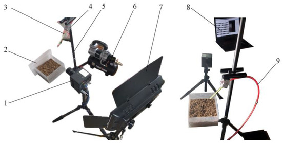
Figure 5.
Stem mustard aerial injection seeding test stand (1. high speed camera; 2. soil tank; 3. seeding pipe; 4. angle bracket; 5. tripod; 6. air compressor; 7. sun lamp; 8. computer; 9. pressure-resistant air pipe).
During the test, the air compressor was turned on to provide high-speed airflow for the seeds, and the air compressor charging time was adjusted by a pressure gauge to control the size of the accelerating air pressure (0~1,000,000 Pa) to realise the adjustment of the different injection speeds of the stem mustard seeds.
2.4. Simulation Test
The process after seed entry into the soil was analysed by EDEM software, and the contact parameters between the stem mustard seed and the soil are shown in Table 4 and the physical properties of the clay-wet soil are shown in Table 5 [22,23].
Table 4.
Contact parameters between stem mustard seeds and cohesive soil.
Table 5.
Various parameters of soil simulation model.
The gas-accelerated flow field in the cavity of the stem mustard seeder was simulated and analysed by Fluent 2022 R1 in ANSYS to determine the influence of the internal structural parameters of the seeder on the effect of accelerating the stem mustard seed grains, and ultimately to obtain the structural parameters.
The negative pressure at the inlet of the gas stream and the steady-state gas flow rate were chosen as the evaluation indexes, and the effects of the chamber diameter DC, the length of the mixing zone H, and the inlet diameter D of the mixing zone were analysed by a one-factor test. The test factors and their levels are listed in Table 6.
Table 6.
One-factor test.
Based on the results of the one-factor experimental analysis, a three-factor, three-level orthogonal test protocol was used in this paper. The specific orthogonal test factors and levels are listed in Table 7.
Table 7.
Orthogonal test.
3. Results and Discussion
3.1. Pneumatic Injection Seeding Bench Test Procedure Analysis
In the pneumatic injection seeding stand test, adjusting the angle of the angle bracket and the horizontal plane to change the angle of incidence, adjusting the height of the tripod to change the height of incidence, and adjusting the pressure of the compressor to change the accelerating air pressure to indirectly change the speed of shot seeding [24] are important steps. This pneumatic shot seeding stand test for the angle of incidence of 60°, and the vertical height of 50 mm, respectively, in the pressure of 100,000 Pa, 200,000 Pa, 300,000 Pa, and 400,000 Pa, was conducted to observe the effect of shot seeding, the data are shown in Table 8.
Table 8.
Pneumatic injection seeding bench test data.
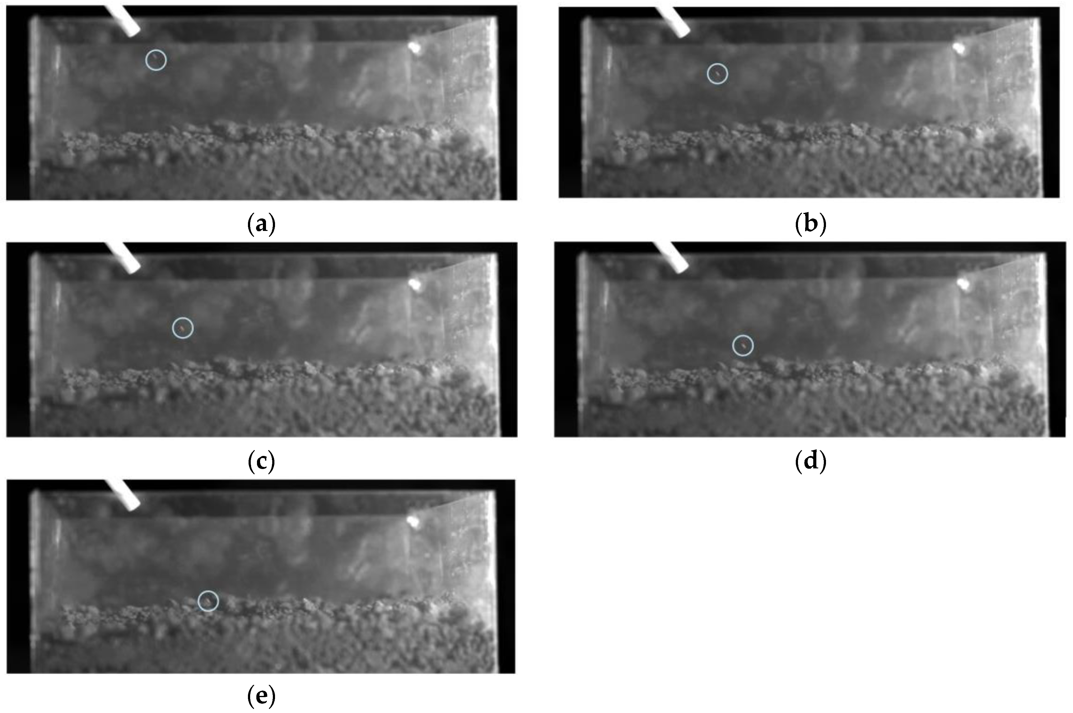
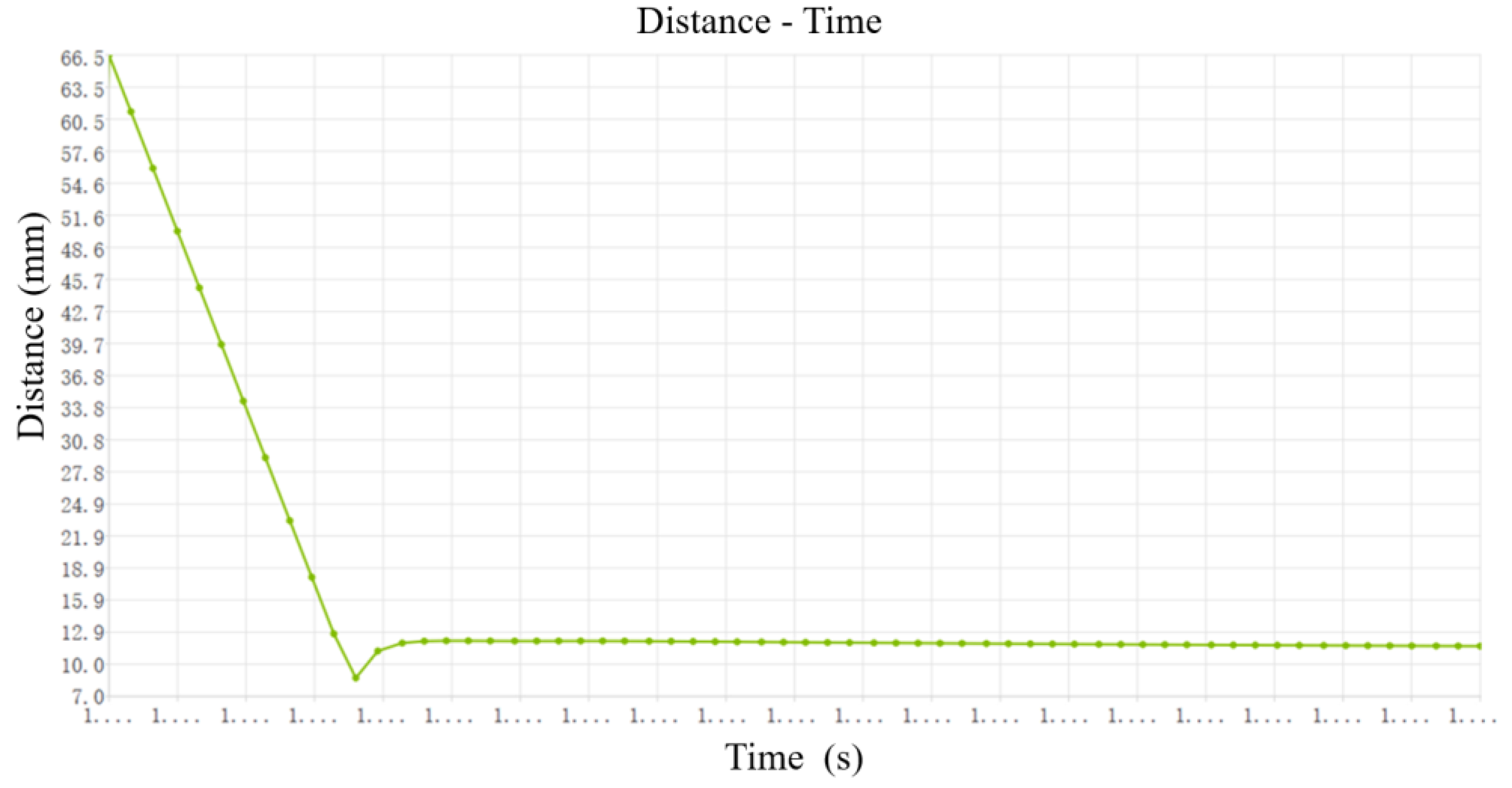
An example of an accelerating air pressure of 100,000 Pa to analyse the process of shot seeding is shown in Figure 6.
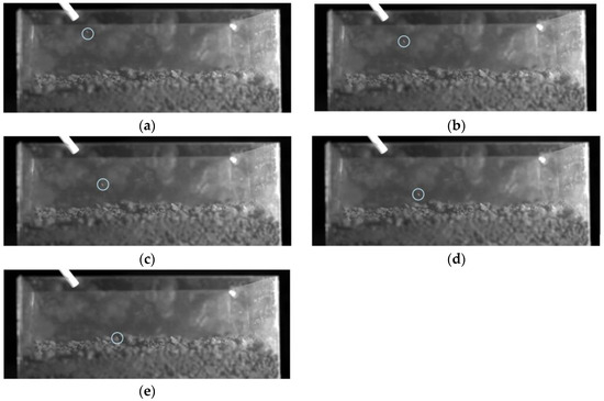
Figure 6.
Example of stem mustard seed shot seeding process. (a). t = 0.6000 s; (b). t = 0.6010 s; (c). t = 0.6020 s; (d). t = 0.6030 s; (e). t = 0.6040 s.
The vertical height is 50 mm, so based on the relationship between the three sides of a 60° right triangle it can be concluded that, from the beginning of the soil to contact, the distance travelled by the seed to the soil is 57.74 mm; from v = s/t, it can be seen that the speed of the injection of seeding is about 12.02 m/s.
At the end of the shot seeding, the high-speed camera data were exported to the computer. The seeds’ approximate location was determined from the pictures taken, followed by ploughing the topsoil layer by layer in the soil slot. When the seeds appeared the ploughing was stopped, and the depth of soil penetration was measured using a Vernier calliper.
According to Table 5, when the acceleration pressure is 100,000 Pa, the seed has not fully entered the soil, so the depth of penetration can be measured on the soil surface as 1.07 mm. However, when the acceleration pressure is 200,000 Pa, the vertical speed is 26.59 m/s, and the seeding depth is 2.79 mm. The seed has fully entered the soil and completed the seeding process, which meets the conditions for seeding into the soil.
3.2. Simulation and Analysis of Soil Penetration Process
Modelling was carried out in EDEM 2021 according to the seed and soil parameters to simulate the process of pneumatic shot seeding of stem mustard seeds into the soil, and to analyse the depth of shot seeding corresponding to different shot seeding speeds, as the seed will rebound when it comes into contact with the soil, which will lead to a reduction in the depth of seed shot seeding, so the rebound phenomenon should be taken into account as well.
As shown in Table 9, the seed shot sowing speed of 20 m/s basically meets the shot sowing depth requirements, and there is no rebound phenomenon. Now the analysis is carried out under conditions where the shot seeding speed is 50 m/s. The simulation results are shown in Figure 7.
Table 9.
Single-factor simulation test data with an incident angle of 60°.
Figure 7.
Simulation results.
According to the simulation process and results in Figure 7, it can be seen that when the speed of shot seeding is 50 m/s, the seed particles start to contact the soil after a short diagonal movement in the air, reached a deepest depth of about 8.5 mm into the soil after collision with soil particles, was rebounded by about 3.8 mm, and then stopped at a depth of 4.7 mm. Although the seed contacted the soil experienced the rebound effect of soil particles to make the seed slightly rebound, it can enter the soil to achieve the effect of shot seeding.
Combined with the results of the one-factor simulation test data in Table 9, it can be seen that when the angle of incidence of the seed is 60°, the seed can completely enter the soil at a certain initial speed to achieve the effect of sowing, and the depth of shot seeding increases with the increase in the speed of shot seeding. The trial does not currently take into account the forward speed of the device, and there is an effect of the movement of the device on the depth of seed shot sowing [25].
3.3. Simulation of Aerodynamic Shot Seeding Analysis
The flow rate of the airflow in the seed discharge device can be improved by the structural design, by setting the inlet at the air inlet as the pressure inlet (the inlet gauge pressure is 100,000 Pa) boundary condition, setting the seed inlet and the accelerator pipe outlet as the pressure outlet (the outlet gauge pressure is 0 Pa) boundary condition, and analysing the different structural parameters through the one-factor test.
3.3.1. Outlet Pipe Diameter
A one-factor test was conducted by setting the mixing zone length H to 15 mm and the diameter D of the mixing zone inlet to 15 mm to explore the velocity field variation of the pneumatic stem mustard shot seeder at the symmetric cross-section ratio of the outgassing chamber diameter DC. The experimental results are shown in Figure 8.
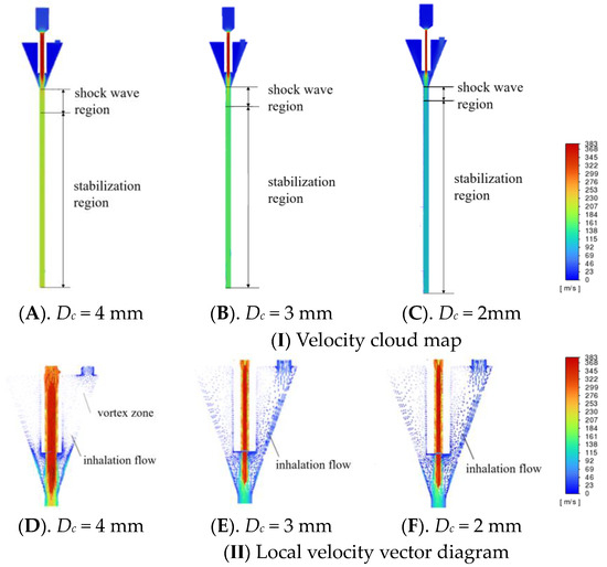
Figure 8.
Velocity field of single-factor test of outlet chamber diameter.
According to the experimental results, Figure 8I shows that a supersonic flow of about 352 m/s is generated during the entry of a high-pressure gas flow in the outlet pipe. After passing through the outlet pipe, the supersonic flow will form a shock wave in the mixing zone, which is an interruption formed by the superposition of weak perturbations and exhibits a strong nonlinear effect, which causes the gas to be compressed suddenly and form a boundary. After the shock wave, the pressure, density, and temperature of the gas will increase significantly, while the flow rate decreases dramatically. Next, with the continuous compression and expansion, the shock wave gradually disappears and a steady-state region is formed inside the acceleration pipe, producing a uniform and stable positive-pressure accelerated gas flow. The different diameters of the outlet pipe correspond to the different ranges of the shock wave region. It was shown that the turbulence intensity of the flow field could be reduced by decreasing the shock wave region [26]. It was shown that reducing the shock wave area could reduce the turbulence intensity of the flow field, thus making the acceleration process of the stem mustard seeds in the accelerating pipe smoother. The size of the stationary region varied when the outlet pipe diameters were 2, 3, and 4 mm, with the largest being when the outlet pipe diameter was 2 mm and the smallest when the outlet pipe diameter was 4 mm. However, a good positive-pressure accelerating airflow field is obtained at all these diameters.
As can be seen in Figure 8II, when the diameter of the outlet chamber is 2 mm and 3 mm, the lower part of the inlet port does not produce a local vortex zone. The gas inhalation flow line is smooth, which is favourable for the stable inhalation of the stem mustard seed grain. When the diameter of the outlet pipe is 4 mm, the supersonic gas flow impacting the wall surface of the mixing area will produce a local vortex area, which will significantly reduce the inlet negative pressure [27]. This will significantly reduce the inlet negative pressure, which is not conducive to the uniform inhalation of stem mustard seeds and will increase the chance of collision of stem mustard seeds after inhalation.
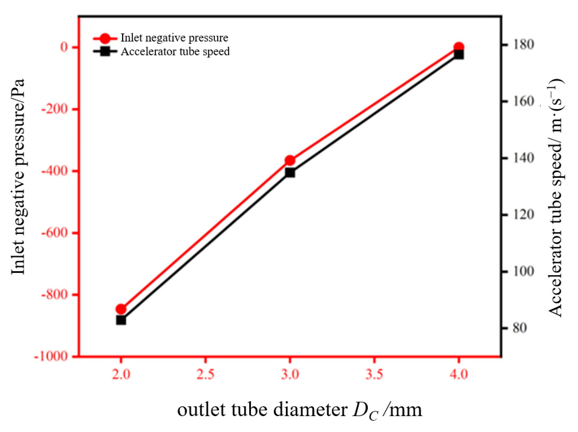
The Fluent numerical extraction function reveals that the diameter of the outlet pipe influences the test metrics. The relevant data are demonstrated in Figure 8. From Figure 9, it can be seen that when the diameter of the outlet pipe increases, the steady-state gas flow rate rises rapidly, fluctuating between 83 and 177 m/s. At the same time, the inlet negative pressure also increases gradually with the increase in the outlet pipe diameter. When the diameter of the outlet pipe DC is 2mm, the inlet negative pressure is the largest, reaching 846.275 Pa; while when the diameter of the outlet pipe DC is 4 mm, a vortex will be formed, resulting in a sharp drop in the inlet negative pressure to a minimum value of 0.031 Pa.

Figure 9.
Effect of outlet pipe diameter on test index.
Based on the overall consideration, the steady-state gas flow rate should be as high as possible to avoid vortexing and to ensure a large negative inlet pressure. This facilitates better acceleration of the stem mustard seeds in the acceleration pipe. Therefore, the diameter of the outlet pipe should be optimally sized at DC = 3 mm. In this case, there is no localised vortex in the lower part of the seed inlet and the shock wave area is smaller. At the same time, the negative inlet pressure is 365.953 Pa and the steady-state gas flow rate can reach 135 m/s.
3.3.2. Mixed Zone Length
A one-factor simulation test of the mixing zone length H was carried out, setting the outlet diameter DC to 3 mm and the mixing zone inlet diameter D to 15 mm. The test results are demonstrated in Figure 10.
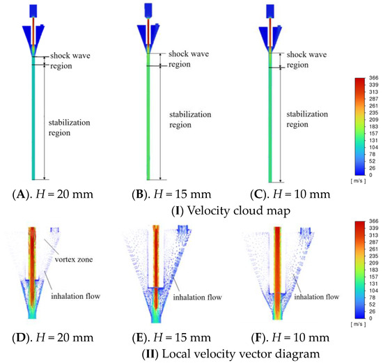
Figure 10.
Velocity field of a one-factor test of the length of the mixing zone.
From Figure 10I, it can be seen that with the increase in the mixing zone length H, the ultrasonic airflow will be diffused within the mixing zone after being ejected from the outlet pipe. By setting the mixing zone length H to 20 mm, the intensity of the excitation wave inside the accelerating pipe can be narrowed and the range of the stabilising region of the airflow can be expanded. In this case, the shock wave zone inside the acceleration pipe is smaller, and the flow field of the positive-pressure accelerated airflow is more stable. In contrast, when the mixing zone lengths H are 15 mm and 10 mm, respectively, the range of the stabilisation region is larger. Therefore, this is more favourable for the acceleration of stem mustard seed grain inside the acceleration pipe.
By observing Figure 10II, it can be seen that there is no regional vortex in the lower part of the seed entry port when the mixing zone lengths H are 15 mm and 10 mm, respectively, resulting in smooth seed inhalation. This contributes to the smooth inhalation process of stem mustard seeds. However, when the mixing zone length H was 20 mm, the supersonic airflow would hit the wall of the mixing zone and lead to the generation of localised vortices. This would be detrimental to the uniform inhalation of the stem mustard seeds. Therefore, it is more appropriate to adjust the mixing zone length H to 15 mm or 10 mm.
Figure 11 shows that with the increase in the mixing zone length, the inlet negative pressure shows a decreasing trend, with a variation range between 21.069 and 602.373 Pa. Due to the generation of vortex, when the mixing zone length H is 20 mm, it leads to a significant decrease in the inlet negative pressure. When the steady gas flows through the mixing zone, its flow rate shows a fluctuating trend with the distance. Specifically, when H is in the range of 10~15 mm, the gas flow rate in the local area shows an increasing trend due to the influence of the accelerator pipe and the throttling effect in the mixing zone. It reaches the maximum value of 135 m/s when the mixing zone length distance H is 15 mm; when the mixing zone length H is between 15 and 20 mm, the stationary gas flow rate decreases gradually with the increase.
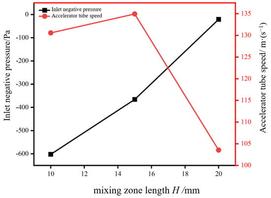
Figure 11.
Effect of mixing zone length on test index.
Based on the overall consideration, it can be concluded that the length of the mixing zone H of 15 mm is more appropriate. In this case, there is no localised vortex in the lower part of the inlet and the shock wave zone is small. At the same time, the negative pressure at the inlet (−365.953 Pa) and the steady-state gas flow rate (up to 135 m/s) are relatively high.
3.3.3. Mixing Zone Inlet Diameter
A one-factor simulation test was conducted to test the effect of the mixing zone inlet D by setting the outlet pipe diameter DC to 3 mm and the mixing zone length H to 15 mm. The experimental results are shown in Figure 12.
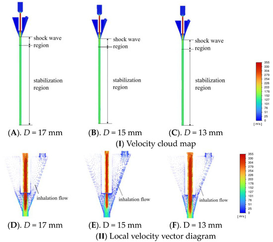
Figure 12.
Mixing zone inlet diameter single-factor test velocity field.
Based on the data shown in Figure 12, it can be seen that the extent of the shock wave zone does not vary much with different mixing zone inlet diameters, which suggests that their steady-state zones also do not differ significantly. When the mixing zone inlet diameter D is 13, 15, and 17 mm, respectively, there is no appearance of a vortex. However, when the mixing zone inlet diameter D is 15 mm, the inhalation flow of gas into the mixing zone is smoother. The effect of the diameter of the mixing zone inlet on the experimental index is shown in Figure 13.
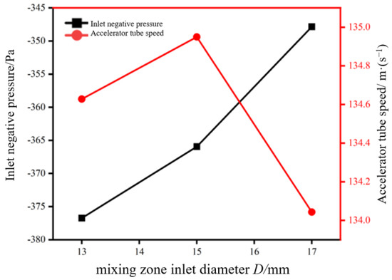
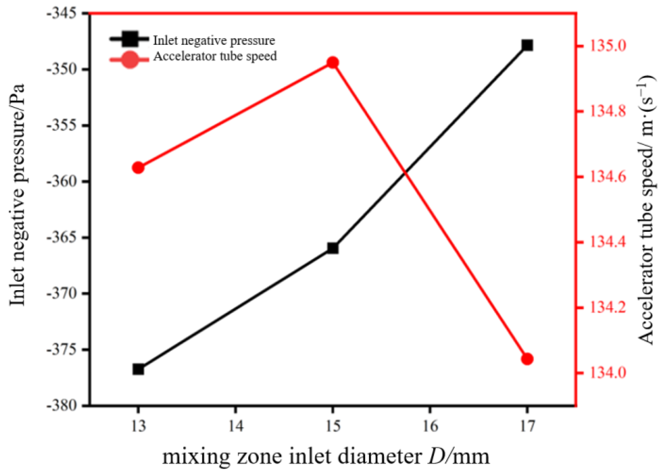
Figure 13.
Effect of mixing zone inlet diameter on test indicators.
According to the results in Figure 13, the steady-state gas flow rate tends to increase and then decrease with the increase in the receiving chamber diameter. When the receiving chamber diameter D reaches 15 mm, the maximum value of the steady-state gas flow rate is 135 m/s. In addition, the negative inlet pressure also decreases with the increase in the inlet diameter of the mixing zone. When the inlet diameter D of the mixing zone is 13 mm, the maximum inlet negative pressure of 376.739 Pa is obtained.
After synthesising the above analysis, it can be concluded that a mixing zone inlet diameter of D = 15 mm is a more ideal choice. With this size, there is no local eddy current in the lower part of the inlet, the area of the shock wave zone is minimised; the maximum value of the steady-state gas flow rate is 135 m/s, and the gas enters the mixing zone with a smoother inhalation flow line. Therefore, this size design can meet the requirements and improve the system’s performance.
3.4. Orthogonal Test Results
The orthogonal test program and results are shown in Table 10. A, B and C are the factor level values, which correspond to the outlet pipe diameter DC, mixing zone length H, and mixing zone inlet diameter D.
Table 10.
Orthogonal test scheme and results.
To study the influence of the steady-state gas flow rate and inlet negative pressure on the test results, this paper carried out the extreme difference analysis and ANOVA for these two indicators. The specific analysis results are detailed in Table 11 and Table 12.
Table 11.
Results of the extreme difference analysis.
Table 12.
Analysis of variance results.
According to the results of ANOVA, the outlet pipe diameter DC has a significant effect on both the inlet negative pressure and the steady-state gas flow rate, whereas the mixing zone length H only has a significant effect on the inlet negative pressure and has a non-significant effect on the steady-state gas flow rate. The mixing zone inlet diameter D has no significant effect on both indicators.
The optimal combination of inlet negative pressure at the seed inlet is A1B1C2, and the optimal combination of steady state gas flow rate is A3B3C2; the larger the inlet negative pressure is, the better the seed inhalation performance will be in the case of satisfying the gas flow rate of the stem mustard seed injection seeding. The presence of the local vortex is also to be taken into account. Therefore, it is suggested to select the combination with an outlet pipe diameter DC of 2 mm, mixing zone length H of 10 mm, and mixing zone inlet diameter D of 15 mm, i.e., combination A1B1C2.
3.5. Verification of Seeding Performance
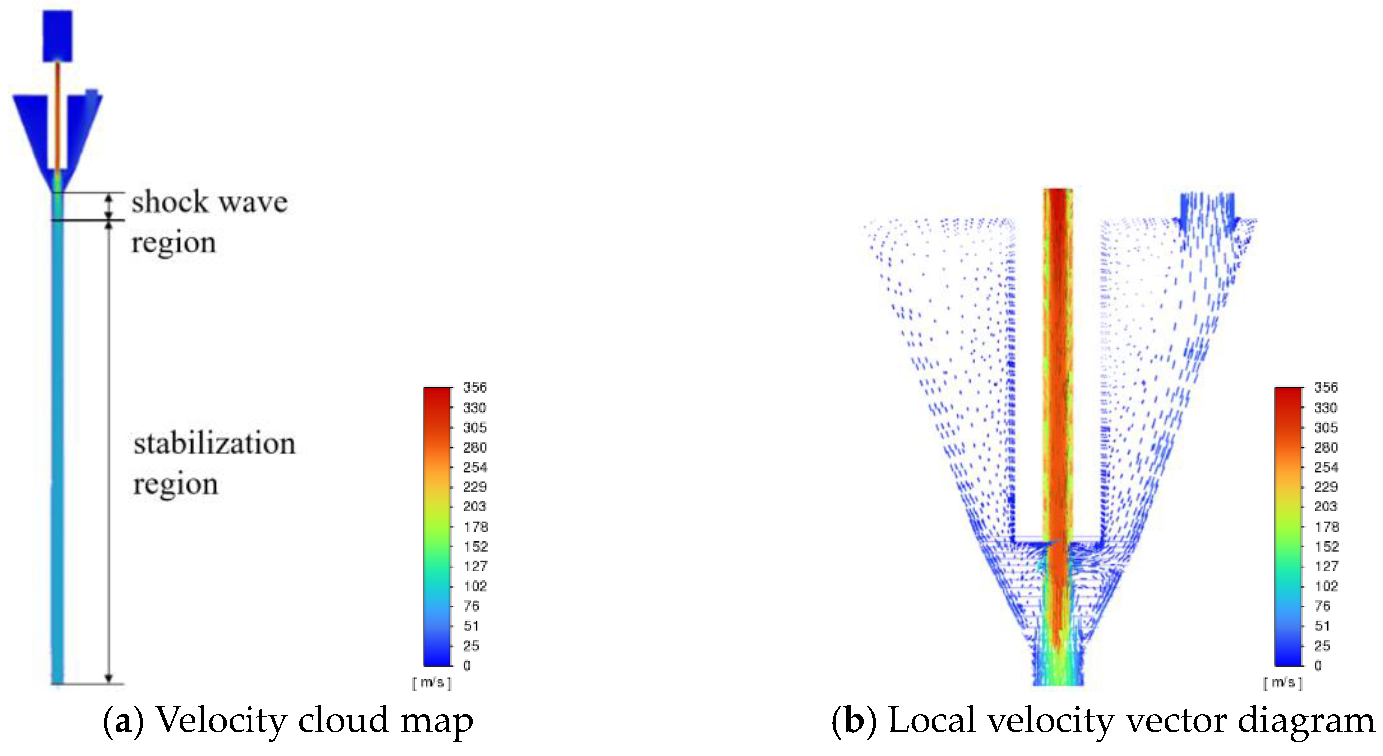
Based on the analysis, it can be concluded that the optimum shot seeding parameters for stem mustard are when the outlet pipe diameter DC is 2 mm, the mixing zone length H is 10 mm, and the mixing zone inlet diameter D is 15 mm. Figure 14 demonstrates the velocity clouds and local velocity vectors for the most effective structural parameters obtained during the simulation using Fluent modelling.
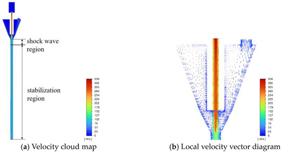
Figure 14.
Velocity field with better structural parameters.
Using the Fluent numerical extraction function, the inlet negative pressure was 900.544 Pa, and the steady-state gas flow rate reached 80 m/s. Observation of Figure 14 showed that there was no localised vortex in the lower part of the seed inlet, and also that the shock wave zone was small. Based on the previous analysis of the aerodynamic acceleration characteristics of the stem mustard seed grain, the optimal combination of numerical analysis results was substituted into Equation (5) and solved by integration, and the velocity of the stem mustard seed grain vm was calculated to be about 32.3 m/s.
According to the analysis of bench test research, to realise the vertical shot seeding of stem mustard seeds into the soil, the vertical component of the shot seeding velocity needs to be greater than or equal to 26.59 m/s, so that the seeds can be completely and stably shot seeded into the soil. Therefore, under the better structural parameters, the device can fully realise the pneumatic shot seeding of seeds.
4. Conclusions
In order to achieve the precise sowing of stem mustard under sticky and wet soil conditions, this paper proposed a pneumatic shot seeding method for stem mustard seeds and analyses the injection seeding process in conjunction with the device. The function of the device is to enable no-tillage sowing of stem mustard seeds, saving costs and improving sowing efficiency.
- By analysing the mechanism of pneumatic seed insertion, and analysing the process of seed insertion, acceleration, insertion, and contact with the soil, the high-speed camera has determined that the conditions for seed insertion can be met at 200,000 Pa and a vertical speed of 26.59 m/s.
- When the inlet air pressure is 100,000 Pa, the vertical velocity of the seed reaches the requirement of shot seeding through the optimisation of the structure. It was found that the best results were achieved when the diameter of the outlet pipe DC was 2 mm, the length of the mixing zone H was 10 mm, and the diameter of the inlet of the mixing zone D was 15 mm. In order to verify the optimised structural parameters, seed casting performance tests were carried out in this study. The experimental results showed that under this device, the vertical velocity of stem mustard seed grain was about 32.3 m/s, which could be completely and stably shot seeded into the soil. The above results showed that the optimised pneumatic stem mustard injection seeding device was able to achieve pneumatic shot seeding of seeds.
- Based on the current technology for precision sowing of small-sized seeds, this paper applies pneumatic shot seeding to stem mustard sowing, which satisfies both precision sowing of small-sized seeds and sowing under no-tillage conditions, and enables two rows to be sown at the same time. The future research will focus on precision sowing and improve and optimise the seed feeding effect. This will be followed up by observing the germination rate of the seeds, as well as examining whether different shot seeding pressures cause damage to the seeds.
Author Contributions
Conceptualisation, Q.N. and W.Y. (Wei Yu); methodology, Q.N.; software, Q.N., H.Z. and W.Y. (Wenhao Yan); validation, Q.N., L.W. and W.Y. (Wei Yu); formal analysis, Q.N. and L.W.; investigation, Q.N. and W.Y. (Wei Yu); resources, C.W.; data curation, W.Y. (Wenhao Yan) and H.Z.; writing—original draft preparation, Q.N.; writing—review and editing, Q.N., C.L., W.Y. (Wenhao Yan) and H.Z. All authors have read and agreed to the published version of the manuscript.
Funding
This work was supported by the Natural Science Foundation of Chongqing, China (cstc2021jcyj-msxmX1178) and the Fundamental Research Funds for central Universities (SWU120004).
Institutional Review Board Statement
Not applicable.
Data Availability Statement
Data are contained within the article.
Conflicts of Interest
The authors declare no conflicts of interest.
References
- Tian, C.; Ye, S.; Li, S. Molecular characterization of viruses and their strains infesting clasp mustard and stem mustard in Chongqing. Acta Hortic. Sin. 2019, 46, 738–748. [Google Scholar] [CrossRef]
- Shen, J.; Liu, X.; Ran, G. Identification of seed purity of stem mustard (Brassica juncea) “Fuza 5” using SSR markers. Mol. Plant Breed. 2016, 14, 2447–2452. [Google Scholar] [CrossRef]
- Liu, Y.; Zhang, Z.; Len, R. Response of stem mustard (Brassica juncea) to sowing date and its screening study. Southwest China J. Agric. Sci. 2010, 23, 805–809. [Google Scholar] [CrossRef]
- Xiong, D.; Wu, M.; Xie, W.; Liu, R.; Luo, H. Design and Experimental Study of the General Mechanical Pneumatic Combined Seed Metering Device. Appl. Sci. 2021, 11, 7223. [Google Scholar] [CrossRef]
- Chen, Z.; Xue, D.; Guan, W.; Guo, J.; Liu, Z. Performance Optimization of a Spoon Precision Seed Metering Device Based on a Maize Seed Assembly Model and Discrete Element Method. Processes 2023, 11, 3076. [Google Scholar] [CrossRef]
- Wang, Q.; Wang, B.; Sun, M.; Sun, X.; Zhou, W.; Tang, H.; Wang, J. Design and Testing of an Automatic Strip-Till Machine for Conservation Tillage of Corn. Agronomy 2023, 13, 2357. [Google Scholar] [CrossRef]
- Hou, S.; Zhu, Y.; Zhu, X.; Wang, Y.; Ji, W.; Chen, H. Design and experiment of a straw clearing mulching no-tillage planter. Biosyst. Eng. 2022, 221, 69–80. [Google Scholar] [CrossRef]
- Zhu, H.; Wu, X.; Qian, C.; Bai, L.; Ma, S.; Zhao, H.; Zhang, X.; Li, H. Design and Experimental Study of a Bi-Directional Rotating Stubble-Cutting No-Tillage Planter. Agriculture 2022, 12, 1637. [Google Scholar] [CrossRef]
- AMAZONE|Download Centre. Available online: https://cdn.consentmanager.net/delivery/autoblocking/05f60ace8ce6.js (accessed on 5 April 2024).
- Li, F.; Chen, J.; Zhang, J. Theoretical analysis of seed delivery process of air-absorbent seed dispenser. China South Agric. Mach. 2024, 55, 6–10. [Google Scholar]
- Fu, Z.; Li, G.; Li, H. Design and test of spiral booster pipe for pneumatic collecting and discharging system of buckwheat seeder. Trans. Chin. Soc. Agric. Mach. 2023, 54, 37–45+69. [Google Scholar]
- Ye, Y.; Wu, Z.; Yu, T. Experimental study on uniformity of seed distribution by cone seed thrower of plot seeder. J. Agric. Mech. Res. 2024, 46, 179–183. [Google Scholar] [CrossRef]
- Zykin, E.; Kurdyumov, V.; Albutov, S.; Dmitriev, O. Modeling of the sowing process of row crops in laboratory conditions. E3S Web Conf. 2020, 193, 01040. [Google Scholar] [CrossRef]
- Li, P.; Zhang, Y.; Sun, J. Research on the prediction method of precise landing position of sowing unit based on EDEM. J. Agric. Mech. Res. 2024, 46, 41–47. [Google Scholar] [CrossRef]
- Kang, J.; Xiang, Y.; Zhang, C. Analysis and test of seed casting performance of air-absorbing drum-type peanut hole seeder. Trans. Chin. Soc. Agric. Eng. 2022, 38, 1–11. [Google Scholar]
- Li, Y.; Yang, L.; Zhang, D. Performance analysis and structural optimization of air-absorbing high-speed precision seed discharger for corn seed delivery. Trans. Chin. Soc. Agric. Eng. 2022, 38, 1–11. [Google Scholar]
- Koller, A.A.; Taylor, R.K.; Raun, W.B.; Weckler, P.R.; Buser, M.D. Modelling and validation of maize seed orientation by pushing. Biosyst. Eng. 2016, 151, 338–349. [Google Scholar] [CrossRef]
- Zou, R.; Luo, Y.; Chen, L.; Wang, A.; Ju, L.; Du, J.; Wan, Z. Introduction of good varieties and high quality and efficient cultivation technology of stem mustard (squash) in Chongqing. J. Change Veg. 2021, 15, 11–14. [Google Scholar]
- Bartosiewicz, Y.; Aidoun, Z.; Desevaux, P. Numerical and experimental investigations on supersonic ejectors. Int. J. Heat Fluid Flow 2004, 26, 56–70. [Google Scholar] [CrossRef]
- Li, Z.; Liu, F.; Wei, Z. Parameter calibration of a discrete elemental model for stem mustard seeds. J. Chin. Agric. Mech. 2023, 44, 83–90. [Google Scholar] [CrossRef]
- NY/T 52-1987; Method for the determination of soil water content. National Bureau of Standards: Gaithersburg, MD, USA, 1987.
- Wang, Y. Research on the Structure and Loosening Effect of Deep Loosening Shovel Based on Discrete Element Method. Master’s Thesis, Jilin Agricultural University, Changchun, China, 2014. [Google Scholar]
- Zou, N. Design of the Supersonic Nozzle and Its Numerical Simulation and Experimental Study. Master’s Thesis, Nanjing University of Aeronautics and Astronautics, Nanjing, China, 2009. [Google Scholar]
- Zhao, P.; Gao, X.; Su, Y. Investigation of seeding performance of a novel high-speed precision seed metering device based on numerical simulation and high-speed camera. Comput. Electron. Agric. 2024, 217, 108563. [Google Scholar] [CrossRef]
- Wang, Y.; Li, H.; Wang, Q. Design and test of mechanical wheat shot seeder. Trans. Chin. Soc. Agric. Mach. 2020, 51, 73–84. [Google Scholar]
- Liu, J.; Wang, Q.; LI, H. Research on the design and seed suction performance of pinhole pipe type wheat precision spot seeding device. Trans. Chin. Soc. Agric. Eng. 2019, 35, 10–18. [Google Scholar]
- Hongbok, P.; Stephen, D. Heister. A numerical study of primary instability on viscous high-speed jets. Comput. Fluids 2005, 35, 1033–1045. [Google Scholar]


Disclaimer/Publisher’s Note: The statements, opinions and data contained in all publications are solely those of the individual author(s) and contributor(s) and not of MDPI and/or the editor(s). MDPI and/or the editor(s) disclaim responsibility for any injury to people or property resulting from any ideas, methods, instructions or products referred to in the content. |
© 2024 by the authors. Licensee MDPI, Basel, Switzerland. This article is an open access article distributed under the terms and conditions of the Creative Commons Attribution (CC BY) license (https://creativecommons.org/licenses/by/4.0/).