Abstract
Manure distribution in soil creates a ground environment that is conducive to crop cultivation. However, the lumping and concentration of manure in the field can occur, hindering the fertilization of the soil for plant growth, and the randomization of nutrients under different soil depths accelerates it. To overcome the challenges associated with agricultural testing, such as high cost, inclement weather, and other constraints, computational analysis is often used. In this study, rotary operations are performed using the discrete element method (DEM) to ensure the uniform distribution of manure and four soil layers. DEM analysis was conducted with three experimental factors, and simulation sets were designed using the Box-Behnken central combination method. The DEM results were evaluated using the uniformity index (UI), and the field test of the rotary operation was performed with the set showing the most uniform distribution among the results. Due to undistinguishable particles in reality, the uniformity was validated by a comparison of the chemical characteristics of the L1 and L5 in terms of before and after the rotary operation. The DEM parameter of the soil was determined by performing field measurements at different soil depths (0–20 cm), and this parameter was calibrated by conducting a penetration test. The Box–Behnken central combination method was implemented using the following factors: tillage depth (X1), PTO revolution speed (X2), and forward machine velocity (X3). These factors were obtained using the UI regression model and the response surface method. In the results, it was indicated that the UI was affected by the factors in the following order: X1 > X2 > X3. The optimized factor values were X1 = 25 cm, X2 = 800 RPM, and X3 = 1.8 km/h, leading to a UI of 6.07, which was consistent with the analysis results. The operating parameters were maintained throughout the field test, and the acquired data were input into the measurement system. The lowest UI value of 6.07 had the strongest effect on decreasing the disparity between L1 and L5, especially in terms of pH, organic matter, P, Ca, and Mg. In summary, the results indicated that soil distribution can be controlled by adjusting mechanical parameters to ensure uniform chemical characteristics across various soil depths.
1. Introduction
Rotary operation is one of the fundamental steps in field cultivation, involving the mixing of soil, chemical fertilizers, and compost. Creating rich soil with depth is beneficial for farming because well-mixed soil with natural nutrients improves field productivity and significantly increases farmer income. Furthermore, deep fertilizer placement has a remarkable effect on soil quality [,]. To produce an abundance of nutrient-rich soil, it is important to ensure uniform nutrient distribution across soil depth. In fact, different nutrients reside at different soil depths, such as organic and microbial biomass carbon []. Field studies on nutrient abundance with soil depth have revealed that more nutrients are present at deeper soil depths at sites in Europe [,], Asia [,], and the USA [,,]. However, contrasting results pertaining to the nutrient content level and soil depth have been reported at other sites [,]. The nutrient levels in shallow and deep soils appear to be nonuniform, and it is difficult for crops to uptake all available nutrients owing to this nonuniformity of nutrient distribution in soil, leading to reduced yield and inviting research into this problem [,]. In addition, studies have demonstrated that similar root uptake is a function of soil depth [,], and significant levels of soil microbial communities exist with increasing soil depth []. In previous studies, the distinct requirements to rearrange the soil layers and create a uniform distribution should be satisfied, and the machinery operation is implicated in this. For instance, a study aiming to optimize the rotary operation can lead to uniform nutrient distribution, resulting in the provision of sufficient nutrients for plant growth and an increase in farm productivity.
To optimize field operations, repeat field testing is the most direct method. However, repeating the rotary operation is time-consuming and cost-intensive when constructing a nutrient-abundant and uniformly distributed field environment []. Therefore, computational and numerical simulations are often implemented using the discrete element method (DEM) []. Many soil–tool interaction models, along with calibration measures, have been developed for investigating forces and soil disturbances []. To obtain accurate results, the following three steps must be implemented: (1) define the contact model, (2) investigate the input parameters, and (3) calibrate soil properties by referring to previous studies.
Setting up an appropriate contact model requires an understanding of the humid soil environment and soil conditions. Most shallow, intermediate, and deep soil regions are wet and easily become clods of clay, even when the soil surface is dry. Therefore, a suitable contact model for DEM should consider soil cohesiveness, such as the Edinburgh elastoplastic adhesion (EEPA) model and the linear parallel bond model [,]. Asaf et al. (2007) used cohesion in their DEM study of soil tillage [], and Aikins et al. (2021) considered adopting cohesion in their model []. However, few soils have small cohesion values that have little influence on the results. Nevertheless, to validate measured and simulated data, soil cohesiveness should be considered when creating the desired soil environment [,]. Therefore, it is suitable to take plastic deformation into account for soil interaction, especially considering an agricultural operation such as tillage or rotavating.
In terms of determining the proper DEM parameters, Kim et al. (2021) reported the variation of various soil properties with soil depths to analyze the draft force as a function of the tillage depth []. In addition, Du et al. (2022) discussed various soil parameters as a function of depth to improve the reliability of the DEM results []. Similarly, soil parameters have been measured by taking several soil samples [,,,]. According to previous DEM analyses pertaining to outdoor soil operations, soil has a random and heterogeneous nature, and it exhibits a nonlinear behavior that differs between different sites []. Thus, direct measurements of input parameters, such as the bulk density, the frictional coefficient, the angle of repose, and water content, are essential, and the manner in which the particle parameter is defined significantly affects the results. Furthermore, the separate properties of the different soil layers have to be defined, and field measurements are essential for the DEM analysis.
To obtain accurate and reliable DEM results, parameter details and bulk calibration should be determined []. In solving the complex motion of a particle based on Newton’s law, the solution accuracy mainly depends on the shape and size of the created particle, and these factors are compensated for by adjusting the characteristics of the bulk soil through calibration [,]. For an adhesive particle, calibration should be performed considering the interaction force between the material and bonded particle [,]. Meanwhile, the performance of agricultural operations, such as tillage, subsoiling, and traction, can be determined by conducting a penetration test [,,,]. Bulk compensation can be performed considering the soil depth, and the individual DEM parameters of each layer can be applied to improve simulation accuracy [,,,,,].
Using classical methods and trial-and-error to optimize agricultural operations is time-consuming [] and the existing potential dangers that are present while performing the agricultural operation should be avoided, but the data to be obtained are still required for greater understanding. To improve our understanding, various experimental design methods can be used to shorten the experiment times and demonstrate the reliability of prediction models [,,]. The response surface method (RSM) is an appropriate method for use in this experimental design because it optimizes machine performance by employing various factors [] during the calibration of the DEM parameters [,].
In this study, a numerical granular study based on the cohesive contact model is conducted using DEM software (V4.4.1, Rockwell Automation Inc., Pittsburgh, NJ, USA). A rotary operation is designed using the Box–Behnken design method, and the uniformity index (UI) of particle layers and the reaction force against the machine are evaluated. Finally, optimization is performed using the response surface method (RSM), and a set of rotary operations for achieving uniform nutrient distribution in soil is obtained.
2. Materials and Methods
2.1. Measurement of Soil and Manure Properties
Soil properties were measured directly in an open field located at 18, Myeong-ri, Seohu-myeon, Andong-si, Gyeongsangbuk-do, Republic of Korea (36°36′10.4″ N, 128°39′41.03″ E). The field was divided into 10 sites by using the uniform grid SAMPLING method [], and one soil sample from each of the four layers (1st layer (L2): 5–10 cm; 2nd layer (L3): 10–15 cm; 3rd layer (L4): 15–20 cm; and 4th layer (L5): 20–25 cm) was taken from each site, as illustrated in Figure 1a, by using a sampling apparatus (4.7 cm in diameter and 15 cm in height) (SL09112, Shinill Science Inc., Paju, Republic of Korea). The soil sample from each depth was taken, maintaining its structure in the cylinder by removing the apparatus. Soil density was computed using the weight (PAG4102, OHAUS Co., Ltd., Parsippany, NJ, USA) and volume of each sample (referenced volume of soil sampling apparatus), and the Young’s modulus of the samples was determined using a universal testing machine (LTCM-100, Chatillon, New York, NY, USA) and force gauges (DFX 2, AMETEK. Inc., Pennsylvania, NJ, USA) (Figure 1b). The measured parameters of the soil samples were interactively utilized to determine the DEM input parameters. Finally, the soil samples obtained from each layer were dried in an oven (SN-110, Shinnong Co., Ltd., Gimcheon, Republic of Korea) at 110 °C for 24 h to determine their moisture contents [,].
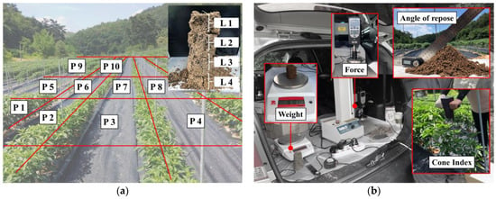
Figure 1.
Soil measurement system: (a) measured points and (b) measured components.
The cone index of the samples was measured by conducting a cone penetration test [] using a cone penetrometer (HJ-4500, Heungjin, Gimpo, Republic of Korea) based on the soil cone penetration test suggested by ASABE Standards [,]. The test was performed ten times, and the average cone index was computed to compensate for the high standard deviation []. An angle of repose test was performed using a soil-filled cylinder, and the inclination angle was measured after removing the cylinder, with the remaining soil forming a heap [,].
Considering the properties of manure, pig manure was used in this study (Figure 2). The particle shape was assumed to be spherical, and the particle size was categorized based on four classes of lump sizes (A: 50 mm, B: 40 mm, C: 30 mm, D: remained). Then, the distribution of the four classes was applied in the DEM analysis. Bulk density was determined by filling the cylinder to 150 mL [] with manure and weighing it on a scale (PAG4102, OHAUS Co., Ltd., Parsippany, NJ, USA). Finally, the manure was oven-dried at 103 °C for 24 h to determine its moisture content [].
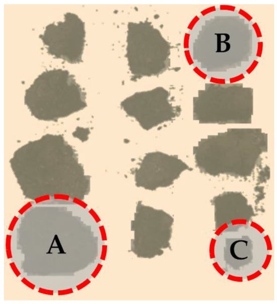
Figure 2.
Distribution of manure particle size.
The soil sample was loam with 39.63% sand, 37.51% silt, and 21.8% clay. The measured soil properties according to soil depth were as follows. The bulk densities of layers L2, L3, L4, and L5 were 1235.7 kg/m3, 1481.2 kg/m3, 1725.1 kg/m3, and 2118.9 kg/m3, respectively (Table 1). A comparison of these bulk densities revealed that the deeper layers had higher densities, and the bulk density of soil increased by 19.72% on average as the soil depth increased by 5 cm. The cone indexes at L2, L3, L4, and L5 were 156.1 kPa, 247.4 kPa, 366.9 kPa, and 539.3 kPa, respectively. Both measured and represented DEM input parameter values were selected [], and similar soil modeling results [] and soil properties with manure [] have been reported in other studies.

Table 1.
Soil and manure parameters obtained in Rocky-DEM simulation.
2.2. Agricultural Vehicle Used for the Field Experiment
The rotary implement (BG600, Bulls Co., Ltd., Sungju-gun, Republic of Korea) used in this work was a general agricultural machine used for tilling, and its specifications are listed in Table 2. The operating width was 120 cm, the suggested operating depth was 23–25 cm, and the PTO (Power Take-off) revolution speed was 440–800 RPM. This implement was used in the DEM simulation and the field experiment to validate the power required for rotary operation and to compare the soil distribution after rotary operation. The vehicle used in the field test was a 14-kW agricultural cultivator (KM-2000, TYM Co., Ltd., Iksan, Republic of Korea) with dimensions of 2650 mm × 1400 mm × 1900 mm (length × width × height) and a rated power of 14 kW.

Table 2.
Specifications of rotary implement.
2.3. DEM Simulation Environment
DEM analysis was performed using Rocky-DEM software (V4.4.1, Rockwell Automation Inc., Pittsburgh, NJ, USA) on a computer equipped with an AMD RyzenTM ThreadripperTM PRO 3975 WX CPU @ 3.5 GHz and 256 GB RAM. To ensure accurate DEM simulation, it is necessary to select the most appropriate contact model. Kim et al. (2021) considered compressibility, adhesiveness, and stickiness by using the EEPA contact model available in EDEM software (Academic 2021) for the DEM of the soil []. Studies have already determined the moisture content of soil and reviewed its effect on the physical properties of soil [,]. Considering the existing DEM analysis methods and the environmental setup of our simulation, we accounted for soil–soil interaction by combining the adhesive force and hysteretic linear spring models in the simulation (Figure 3).
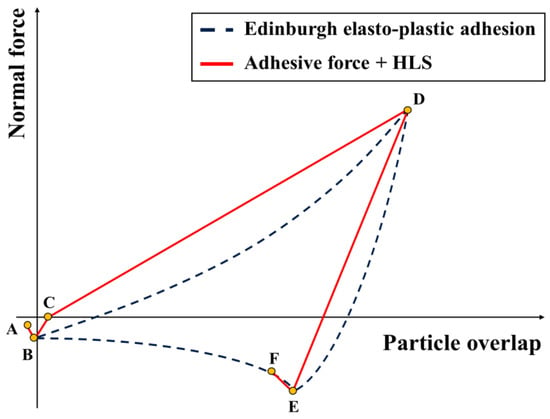
Figure 3.
Comparison between contact model of EEPA and combination of adhesive force and HLS.
The characteristic particle overlap graph of this combination is similar to that of the EEPA contact model available in EDEM software (Academic 2021). Moreover, the normal force between particles can be calculated using the following equations [].
where Fce (N) is the pull-off force, Knl (Nm) is the contact loading stiffness, Knu (Nm) is the contact unloading stiffness, and so, sp, and scp (%) are the overlap limits.
where R (mm) is the effective radius, T (mJ/m2) is the surface energy, and smax (%) is the maximum overlap.
Spherical soil particles were obtained using a soil bin with a radius of 0.7 cm, which was selected considering the simulation accuracy and time []. Moreover, manure particles with the same shape were created with the abovementioned size distribution (0.7, 3, 4, and 5 cm). The total number of particles in the soil bin was 1,159,534. The soil bin was created virtually with a width of 200 cm, a length of 600 cm, and a depth of 25 cm. The soil particles were placed in the bin in order of depth, and manure was sprayed on the top layer (Figure 4). Then, rotary simulation was conducted using different tillage depths (23–25 cm), PTO revolution speeds (440–800 RPM), and forward velocities of the machine (1.2–2.4 km/h) by referring to the literature.
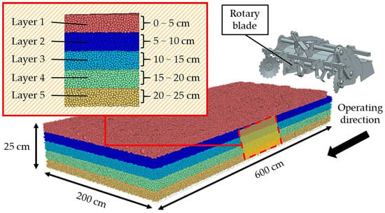
Figure 4.
Created soil bin and soil model.
Table 3 lists the key parameters input into the Rocky-DEM software program (V4.4.1, Rockwell Automation Inc., Pittsburgh, NJ, USA). The accuracy of the DEM result hinges on the key parameters, and therefore these parameters must be calibrated. In this study, the penetration test, which yields the properties of various soil layers, was considered appropriate for calibrating soil particles.

Table 3.
Key parameters used in simulation.
2.4. Measurement of UI
To determine the UI, the proportions of the particle numbers belonging to different layers in a unit volume were computed. The unit volume of cubes in the 125 × 10−6 m3 was used to count the number of particles; the process was simultaneously conducted at 22 different locations with double layers. The 1st and 2nd layers were placed at depths of 0–12.5 cm and 12.5–25 cm, respectively (Figure 5). The average proportion was taken as the UI, according to the following equation:
where RL (%) is the average proportion of each layer, PL is the number of each particle in each layer, and PT is the total number of particles (L1: 0–5 cm, L2: 5–10 cm, L3: 10–15 cm, L4: 15–20 cm, L5: 20–25 cm).
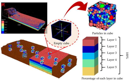
Figure 5.
Determination of uniformity index in DEM simulation.
Then, five different soil layers were created in the bin and were considered equally distributed when the RL of each layer was 20% as a median. The RL deviated from 20%, root-mean-square (RMS) UI in relation to the deviation from the uniform particle distribution, as follows:
where UI (%) is the percentage of distribution in each particle layer (L1: 0–5 cm, L2: 5–10 cm, L3: 10–15 cm, L4: 15–20 cm, and L5: 20–25 cm) within the cube.
2.5. Design of Experiment
To perform the rotary operation, Dai et al. (2020) identified the following as key working factors: the tillage depth, the PTO revolution speed, and the machine forward velocity []. The level of tillage depth should be greater than 0.5 cm, starting at 24 cm, and the forward velocity should be 1.8 km/h. In view of these constraints, we set three levels for each factor in the DEM simulation. The experimental set was designed using the Box–Behnken central (BBC) combination theory, and the factors are listed in Table 4. Three factors, namely tillage depth, PTO revolution speed, and forward machine velocity, were used in the DEM simulation, and their ranges were 23–25 cm, 440–800 RPM, and 1.2–2.4 km/h, respectively.

Table 4.
Experimental set created using Box–Behnken central (BBC) combination theory.
2.6. Field Measurement System
The rotary operation for experimentally studying the effects of the suggested operating parameters on soil distribution was performed with the data acquisition system (Figure 6). A torque measurement system was constructed to measure the torque acting on the PTO shaft and the revolution speed of the shaft by using a strain gauge equipped with a transmitter (V3-BNN-1CH, SMART C&S, Daejeon, Republic of Korea) and a photosensor (BRQT3M-PDTA, Autonics, Busan, Republic of Korea). This torque measurement system was installed on the surface of the PTO shaft, and an RPM measurement system was installed on the PTO frame box by using a magnetic support jig to ensure that the system could not detach or fall off during data acquisition. The field test was conducted with a travel distance of 10 m, and the operating soil depth was measured at intervals of 1 m, including the start point.
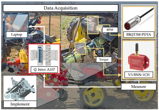
Figure 6.
Schematic of field measurement system with agricultural machine.
2.7. Chemical Analysis of the Soil Sample
A low UI value indicates a well-mixed soil with a constant nutrient value in different soil layers. To validate the effect of UI, the chemical compositions of L1 and L5 before and after rotary operation were compared. The general chemical properties of the soil (including pH, EC, organic, phosphate, potassium, calcium, and magnesium) were analyzed based on the specific standard method [] (Figure 7).
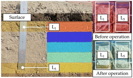
Figure 7.
Top and bottom layers of soil sample for comparison of chemical analysis.
2.8. Statistical Analysis
The UI and the selected variables were statistically analyzed using the RSM and prediction models. Analysis of variance of each variable was performed using Minitab 22 and built on the published results. Please note that the publication of your manuscript that provided approval and the corresponding ethical approval code.
3. Results and Discussion
3.1. Properties of the Soil Model
The DEM particle was calibrated by performing a penetration test. In the Rocky-DEM simulation, each particle layer was created in the cylinder (10 cm in diameter and 25 cm in height), and the cone tip was pushed into the cylinder at a velocity of 0.3 m/s [,]. The corresponding cone index with soil depth (Dn) is depicted in Figure 8. The cone index values of D1, D2, D3, and D4 were 151.1 kPa, 252.5 kPa, 375.0 kPa, and 549.4 kPa, respectively, and the differences between the measured and simulated values were 3.2%, 2.1%, 2.2%, and 1.9%. The cone index of the site was smaller than 600 kPa, indicating the presence of soft soil that had been tilled recently. Moreover, in the validation test, the cone index values at each depth in the field site were 78.6 kPa, 247.7 kPa, 349.3 kPa, and 524.8 kPa, which were similar to the values at D2, D3, and D4; however, the value at D1 was smaller than that obtained from the soil sample (Figure 8).
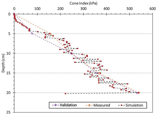
Figure 8.
Result of soil model calibration.
3.2. Effects of Each of the Parameters on UI Value
The experimental results are listed in Table 5. The lowest UI was found for design #5 (X1: 25 cm, X2: 800 RPM, and X3: 1.8 km/h), while design #7 (X1: 23 cm, X2: 600 RPM, and X3: 2.4 km/h) had the highest UI. The BBC design results generally indicated that greater depths, higher PTO revolution speeds, and smaller forward machine velocities led to more uniform nutrient distribution in the soil field with low UI.

Table 5.
Results of Box–Behnken design.
To predict the UI, the following constants and coefficients were used: X1, X2, X3, X22, X32, X1×2, and X2×3; the factor X12 and the coefficient X1×3 were not significant in the regression equation. The single factors X1, X2, and X3 affected the UI significantly, with p-values smaller than 0.01. However, among the interaction factors, only X1×2 and X2×3 affected the UI significantly, with confidence intervals greater than 95% (p < 0.05). Moreover, the multiple factors X22 and X32 significantly affected the UI with significance levels of less than 0.01 (p < 0.01). The factors with negative coefficients strongly influenced the uniform construction of the environment with reduced UI, while the factors with positive coefficients increased the UI. For instance, if X1 (negative coefficient, −4.962) increased, a low UI value was returned as the result. The regression model of the UI in terms of the dependent variable is as follows:
The statistical analysis results indicated that the order of influence on UI was X1 > X2 > X3, and the lack-of-fit p-value of the regression model (0.145) indicated that no other factors affected the index significantly. Furthermore, the coefficient of determination R2 and the adjusted coefficient of determination Radj2 were 99.2% and 97.7%, respectively. However, the predicted coefficient of determination Rpre2 was 88.3%, which was smaller than R2. Nevertheless, considering that the predicted objective is an environmental factor, the value is reasonable, and the difference between Radj2 and Rpre2 is less than 0.2% (Table 6).

Table 6.
Variance analysis of uniformity.
3.3. Effect of UI Value on Soil Distribution
For the UI value obtained using design #5, a comparison between the initial particle distribution in each cube within the bin and that after rotary operation is presented in Figure 9. Additionally, the design sets that yielded the lowest and highest UI values (6.07 and 20.83, respectively) were compared. Initially, each layer was clearly separated, with L4 and L5 in the bottom cubes (a depth of 12.5–25 cm), L1 and L2 in the top cubes (a depth of 0–12.5 cm), and L3 being invisible. Then, the particles of all layers were identified in every cube after rotary operation, but the ratios of each of the layers were different in terms of the UI value. When the UI value was 20.83, the ratios of layers L1, L2, L3, L4, and L5 were 17.1 ± 9.5%, 14.1 ± 2.7%, 38.2 ± 3.1%, 18.1 ± 5.5%, and 12.6 ± 6.1%, respectively. While design #5 afforded higher uniformity with a UI value of 6.07, the ratios of layers L1, L2, L3, L4, and L5 were 18.2 ± 3.8%, 18.3 ± 5.6%, 25.1 ± 3.6%, 20.3 ± 5.2% and 17.9 ± 5.1%, respectively. The particle ratio of L1, L2 in the bottom layer and L4, and L5 in the top layer had the highest disparity on soil distribution, which indicated that the deeper the rotary blades penetrated the soil, the greater the soil feed ability was (Figure 9).
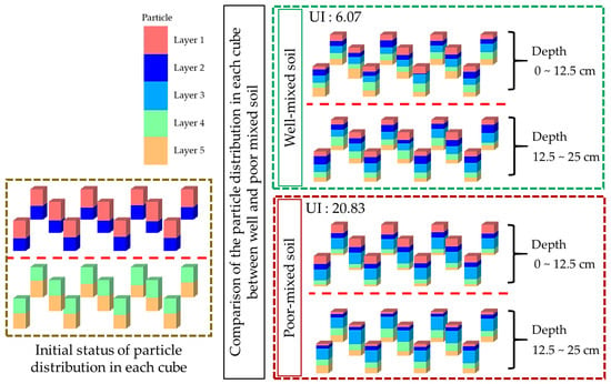
Figure 9.
Results of soil distribution comparison on initial status, the lowest and highest UI values.
The number of particles belonging to each layer was analyzed using the cubes located at different soil depths. Initially, each particle layer was separated into five layers in the forward direction, and during DEM analysis, these layers were mixed and displaced in the cube located in the back section of the soil bin. Based on the selected experimental factors, the most well-mixed soil distribution was obtained when the UI value was 6.07 (Figure 10). This UI value represented small RMS differences between the layers and reflected the uniform distribution of soil particles within the bin. The effects of X1 and X2 on UI seemed intuitive; as the penetration depth of the implement into the soil and the rotating frequency increased, the interchangeability between each of the particle layers increased. Interestingly, level 0 of X3 yielded the lowest UI, which was counterintuitive because neither the longer nor shorter operating time resulted in a well-mixed field site. Considering the operation factors, similar results of the distribution tendency were found with the slower forward velocity through five different soil depths [].
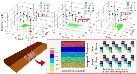
Figure 10.
Results of RSM on UI analysis with each experimental set and soil distribution of the lowest UI value.
Furthermore, the selected method for the formula for calculating the distribution of soil, UI, based on analyzing significant variation from the mean value, seems to have been adopted in general agricultural data analysis []. Compared to other DEM literature results using an adhesive soil model, the selected operation condition in this study can be a more effective method by which to create a uniform soil environment in which a similar level of the distribution index was found at each soil depth in this study, while increasing significant variations were observed []. However, Song et al. (2023) discussed influencing factors that make soil cultivation more complex and decrease simulation accuracy []. Similarly, the validation test in this study was performed through an open field test, while some of the instances in the literature used an indoor schematic system [,,]. The aim of this study was to create a soil environment containing uniform nutrients at each depth. Therefore, performing the outdoor validation test can be a suitable method, taking the natural nutrient itself rather than using second-treated soil for making the soil bin.
To validate the DEM results, a field test of the rotary operation based on design #5 (X1: 25 cm, X2: 800 RPM, X3: 1.8 km/h) was performed, and the resulting state of the field site was compared to the initial state of the field site. To validate the counterintuitive aspect of X3, a comparative design set with a changing X3 was used.
3.4. Validation of Soil Distribution through Chemical Characteristics
Based on the DEM result of design #5, a rotary operation was performed in the field to measure the required power. In addition, a comparative test in which X3 was increased to a higher level (2.4 km/h) was performed to analyze the counter-intuitive effect of this design factor on the UI value. The results of the field test for measuring the power, the sustained PTO revolution speed, and the soil depth at a forward machine speed of 1.8 km/h are presented in Figure 11a. While fluctuating power and RPM curves were observed in the latter part of the test owing to an adjustment of the machine to the travel environment, the average power was 2.4 kW, and the sustained PTO revolution speed was 800 RPM within the actual operating period; for the same design set, the required power according to the DEM result was 2.2 kW. Compared to the target depth of 25 cm, the minimum and maximum operated depths were 23 and 27 cm, respectively, and the average soil depth of 11 points was 25.6 cm (Figure 11a).
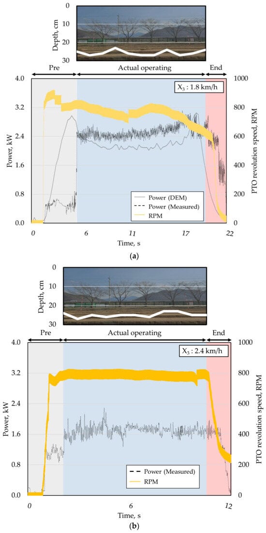
Figure 11.
Operation dataset for DEM and measured model validation: (a) design #5 and (b) comparison.
For comparison, the measured power and sustained PTO revolution speed obtained by varying the forward machine speed to 2.4 km/h are presented in Figure 11b. While the operation time decreased owing to an increase in forward machine speed, the average power of the comparison set was 1.7 kW, and the PTO revolution speed was maintained at 800 RPM. However, in the field test with the comparison set, the target soil depth was not achieved. The average soil depth was 24.9 cm, and this deficiency was observed at four different points among the eleven measurement points (Figure 11b).
The validation results of soil distribution were obtained by performing the rotary operation with design #5, and the chemical characteristics of L1 and L5 were compared, as illustrated in Figure 12. Design #5 yielded the lowest UI value, which indicated the uniformity of chemical characteristics across soil depths. In terms of pH, the overall value in both L1 and L5 was 6.0–6.4, but the difference between these two layers decreased after rotary operation. Moreover, the EC values of the two layers were 0.1–0.2 dS/m, and no significant difference was found, indicating that the ability to provide nutrients was maintained during field operation. However, nutrients such as organic potassium (K), phosphate (P), calcium (Ca), and magnesium (Mg) were transferred to other soil layers relative to the initial status. The organic disparity of L1 and L5 before operation was 8.33 ± 0.5 g/kg (14.3 ± 0.5 and 6.0 g/kg, respectively), but it decreased to 4.3 ± 0.3 g/kg (18.0 ± 4.3 and 13.6 ± 4.0 g/kg, respectively) after the rotary operation. A similar decrease in nutrient disparity was observed: The initial disparity value of K was 0.12 ± 0.03 cmol+/kg (0.23 ± 0.04 cmol+/kg for L1 and 0.11 ± 0.01 cmol+/kg for L5), that of P was 46.34 ±0.04 cmol+/kg (55.67 ± 28.36 cmol+/kg for L1 and 9.33 ± 4.04 cmol+/kg for L5), that of Ca was 1.83 ± 0.6 cmol+/kg (5.07 ± 0.12 cmol+/kg for L1 and 6.9 ± 0.72 cmol+/kg for L5), and that of Mg was 1.13 ± 0.2 cmol+/kg (1.67 ± 0.06 cmol+/kg for L1 and 2.8 ± 0.26 cmol+/kg for L5); these values decreased to 0.04 ± 0.03 cmol+/kg, 0.0 ± 4.62 cmol+/kg, 0.27 ± 0.47 cmol+/kg, and 0.03 ± 0.04 cmol+/kg, respectively, after the rotary operation (Figure 12).
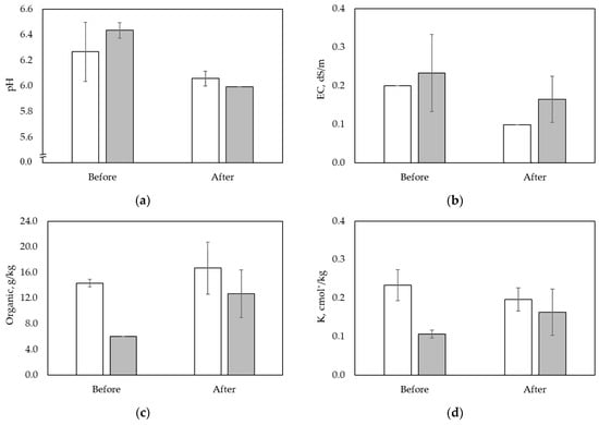
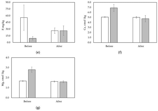
Figure 12.
Comparison results of soil distribution in terms of chemical characteristics before and after rotary operation (a) pH, (b) EC, (c) organic matter, (d) K, (e) P, (f) Ca, (g) Mg (white bar: L1, gray bar: L5).
Consequently, the effects of design #5 (UI value of 6.07) on soil distribution after rotary operation were as follows: the disparity between L1 and L5 decreased, which was consistent with the goal of creating a uniform environment with soil depth. The average disparity values of all chemical characteristics decreased, except that of EC, and decreased deviations were observed, except in the case of K. These results indicated that the rotary operation created a soil environment with uniform pH, organic matter, P, Ca, and Mg, but not uniform EC and K (Table 7). Thus, the statistically identified UI value reflected significant differences in chemical value, which indicated that optimizing the rotary operation can help provide a uniform level of nutrients to the target crop across soil depths, thereby creating a sustainable environment.

Table 7.
Effect of UI value on decreasing disparity.
4. Conclusions
In this study, a rotary operation to ensure uniform nutrient distribution across soil layers (L1–L5) was optimized, and a test was conducted to validate the resulting soil distribution by comparing the chemical characteristics of different soil layers in terms of before and after the target operation. The properties of soil and manure were measured at test sites and used as the DEM input parameters. The experiment set was designed using the BBC method, and 15 sets of DEM analysis were performed. The UI was calculated using the RMS error method and optimized using the RSM. The field test was performed using design #5, and the general chemical characteristics of soil were analyzed and compared to validate the resulting distribution. The conclusions are as follows:
For the UI value, the lowest result, 6.07, was observed with the experiment set of #5 (X1 = 25 cm, X2 = 800 RPM, X3 = 1.8 km/h), and the UI was affected by the factors in order of X1 > X2 > X3, while the multiple factor X12 and the interaction factor X1×3 did not significantly affect the objective, and the regression model was described using these factors. The predicted coefficient of determination (Rpre2) and its adjusted value (Radj2) were 88.3% and 97.7%, respectively. A validation test was performed based on BBC design #5 (X1: 25 cm, X2: 800 RPM, and X3: 1.8 km/h). Sustained operating conditions were provided through a data acquisition system, and soil samples were taken from L1 and L5 before and after the rotary operation. The disparity in the chemical characteristics of the two layers decreased, especially in terms of pH, organic matter, P, Ca, and Mg, resulting in L1 and L5 having similar chemical characteristics. The disparity values of 0.17 ± 0.17, 8.33 ± 0.58 g/kg, 46.33 ± 24.32 cmol+/kg, 1.83 ± 0.61 cmol+/kg, and 1.13 ± 0.21 cmol+/kg were decreased to 0.07 ± 0.06, 4.33 ± 0.32 g/kg, 0 ± 4.62 cmol+/kg, 0.27 ± 0.46 cmol+/kg, and 0.03 ± 0.04 cmol+/kg for pH, organic matter, P, Ca, and Mg, respectively.
However, the results were drawn from the empirical test validating the uniform distribution underground by analyzing the chemical characteristics. A further study to enhance findings would be to cultivate the crop on the field created with #5 and compare its growth and yield to those of the traditional method.
Author Contributions
Conceptualization, S.K. (Seokho Kang) and S.W.; methodology, H.P. and Y.K. (Yonggik Kim); formal analysis, S.K. (Seokho Kang) and J.S.; investigation, S.K. (Seokho Kang), Y.K. (Yonggik Kim), H.P., Y.H. (Yujin Han), Y.J. and S.K. (Seunggwi Kwon); writing—original draft preparation, S.K. (Seokho Kang); writing—review and editing, S.K. (Seokho Kang) and Y.K. (Yeongsu Kim); supervision, Y.H. (Yushin Ha); project administration, Y.H. (Yushin Ha); funding acquisition, Y.H. (Yushin Ha). All authors have read and agreed to the published version of the manuscript.
Funding
This work was supported by the Korea Institute of Planning and Evaluation for Technology in Food, Agriculture, Forestry (IPET) through Open Field Smart Agriculture Technology Short-term Advancement Program, funded by Ministry of Agriculture, Food and Rural Affairs (MAFRA) (322038031SB010).
Institutional Review Board Statement
Not applicable.
Data Availability Statement
The original contributions presented in the study are included in the article material, further inquiries can be directed to the corresponding author.
Conflicts of Interest
Author Seunggwi Kwon is employed by the Bulls Co., Ltd. Author Youngyoon Jang is employed by the Sungboo Co., Ltd. The remaining authors declare that the research was conducted in the absence of any commercial or financial relationships that could be construed as a potential conflict of interest.
References
- Dai, F.; Song, X.; Zhao, W.; Shi, R.; Zhang, F.; Zhang, X. Mechanism analysis and performance improvement of mechanized ridge forming of whole plastic film mulched double ridges. Int. J. Agric. Biol. Eng. 2020, 13, 107–116. [Google Scholar] [CrossRef]
- Li, S.; Liu, Z.; Li, J.; Liu, Z.; Gu, X.; Shi, L. Cow manure compost promotes maize growth and ameliorates soil quality in saline-alkali soil: Role of fertilizer addition rate and application depth. Sustainability 2022, 14, 10088. [Google Scholar] [CrossRef]
- Mousavi, S.R.; Sarmadian, F.; Omid, M.; Bogaert, P. Three-dimensional mapping of soil organic carbon using soil and environmental covariates in an arid and semi-arid region of Iran. Measurement 2022, 201, 111706. [Google Scholar] [CrossRef]
- Braun, L.; Kadmon, R.; Tomiolo, S.; Majekova, M.; Tielborger, K. Is more less? A comprehensive experimental test of soil depth effects on grassland diversity. Oikos 2022, 5, e08535. [Google Scholar] [CrossRef]
- Dlugosz, J.; Piotrowska-Dlugosz, A. Changes in carbon-degrading enzyme activities and microbial biomass content-The effects of soil depth and soil-forming processes. Appl. Soil Ecol. 2022, 180, 104629. [Google Scholar] [CrossRef]
- Liu, Y.; Chen, J.; Zhang, X.; Li, Q.; Du, Y.; Liu, J.; Tao, J. Herbaceous community species composition and productivity are affected by soil depth and funnel effect in a simulated karst experiment. Glob. Ecol. Conserv. 2020, 22, e01033. [Google Scholar] [CrossRef]
- Liu, D.; Huang, Y.; An, S.; Sun, H.; Bhople, P.; Chen, Z. Soil physicochemical and microbial characteristics of contrasting land-use types along soil depth gradients. Catena 2018, 162, 345–353. [Google Scholar] [CrossRef]
- Hao, J.; Chai, Y.N.; Lopes, L.D.; Ordonez, R.A.; Wright, E.E.; Archontoulis, S.; Schachtman, D.P. The effects of soil depth on the structure of microbial communities in agricultural soils in Iowa (United States). Appl. Environ. Microbiol. 2021, 87, e05673-20. [Google Scholar] [CrossRef]
- Zhang, B.; Penton, C.R.; Xue, C.; Quensen, J.F.; Roley, S.S.; Guo, J.; Garoutte, A.; Zheng, T.; Tiedje, J.M. Soil depth and crop determinants of bacterial communities under ten biofuel cropping systems. Soil Biol. Biochem. 2017, 112, 140–152. [Google Scholar] [CrossRef]
- Eilers, K.G.; Debenport, S.; Anderson, S.; Fierer, N. Digging deeper to find unique microbial communities: The strong effect of depth on the structure of bacterial and archaeal communities in soil. Soil Biol. Biochem. 2012, 50, 58–65. [Google Scholar] [CrossRef]
- Zhao, M.; Wang, M.; Zhao, Y.; Hu, N.; Qin, L.; Ren, Z.; Wang, G.; Jiang, M. Soil microbial abundance was more affected by soil depth than the altitude in peatlands. Front. Microbiol. 2022, 13, 1068540. [Google Scholar] [CrossRef]
- Delgado-Baquerizo, M.; Powell, J.R.; Hamonts, K.; Reith, F.; Mele, P.; Brown, M.V.; Dennis, P.G.; Ferrari, B.C.; Fitzgerald, A.; Young, A.; et al. Circular linkages between soil biodiversity, fertility and plant productivity are limited to topsoil at the continental scale. New Phytol. 2017, 215, 1186–1196. [Google Scholar] [CrossRef]
- Goebes, P.; Schmidt, K.; Seitz, S.; Both, S.; Bruelheide, H.; Erfmeier, A.; Scholten, T.; Kuhn, P. The strength of soil-plant interactions under forest is related to a critical soil depth. Sci. Rep. 2019, 9, 8635. [Google Scholar] [CrossRef] [PubMed]
- Hirzel, J.; Matus, I. Effect of soil depth and increasing fertilization rate on yield and its components of two durum wheat varieties. Chil. J. Agric. Res. 2013, 73, 55–59. [Google Scholar] [CrossRef]
- Drescher, G.L.; Silva, L.S.D.; Sarfaraz, Q.; Drescher, M.S.; Brunetto, G.; Silva, A.A.K.D.; Tassinari, A.; Silva, L.O.S.D. Rice nitrogen uptake as affected by different nitrogen application depths. Arch. Agron. Soil Sci. 2021, 67, 53–65. [Google Scholar] [CrossRef]
- Drescher, G.L.; Silva, L.S.D.; Sarfaraz, Q.; Roberts, T.L.; Nicoloso, F.T.; Schwalbert, R.; Marques, A.C.R. Available Nitrogen in Paddy Soils Depth: Influence on Rice Root Morphology and Plant Nutrition. J. Soil Sci. Plant Nutr. 2020, 20, 1029–1041. [Google Scholar] [CrossRef]
- Leewis, M.C.; Lawrence, G.R.; Schulz, M.S.; Tfaily, M.M.; Ayala-Ortiz, C.O.; Flores, G.E.; Mackelprang, R.; Mcfarland, J.W. The influence of soil development on the depth distribution and structure of soil microbial communities. Soil Biol. Biochem. 2022, 174, 108808. [Google Scholar] [CrossRef]
- Sadek, M.A.; Chen, Y.; Zeng, Z. Draft force prediction for a high-speed dis implement using discrete element modelling. Biosyst. Eng. 2021, 202, 133–141. [Google Scholar] [CrossRef]
- Li, X.; Zhu, L.; Gong, S. Soil-cutting simulation and dual-objective optimization on tillage process parameters of micro-tiller by smoothed particle Galerkin modeling and genetic algorithm. Comput. Electron. Agric. 2022, 198, 107021. [Google Scholar] [CrossRef]
- Conte, O.; Levien, R.; Debiasi, H.; Sturmer, S.L.K.; Mazurana, M.; Muller, J. Soil disturbance index as an indicator of seed drill efficiency in no-tillage agrosystems. Soil Tillage Res. 2011, 114, 37–42. [Google Scholar] [CrossRef]
- Nalawade, R.D.; Singh, K.P.; Roul, A.K.; Patel, A. Parametric study and calibration of hysteretic spring and linear cohesion contact models for cohesive soils using definitive screening design. Comput. Part. Mech. 2022, 10, 707–728. [Google Scholar] [CrossRef]
- Zeng, Z.; Chen, Y.; Qi, L. Simulation of cotyledon-soil dynamics using the discrete element method (DEM). Comput. Electron. Agric. 2020, 174, 105505. [Google Scholar] [CrossRef]
- Asaf, Z.; Rubinstein, D.; Shmulevich, I. Determination of discrete element model parameters required for soil tillage. Soil Tillage Res. 2007, 92, 227–242. [Google Scholar] [CrossRef]
- Aikins, K.A.; Antille, D.L.; Ucgul, M.; Barr, J.B.; Jensen, T.A.; Desbiolles, J.M.A. Analysis of effects of operating speed and depth on bentleg opener performance in cohesive soil using the discrete element method. Comput. Electron. Agric. 2021, 187, 106236. [Google Scholar] [CrossRef]
- Ucgul, M.; Fielke, J.M.; Saunders, C. 3D DEM tillage simulation: Validation of a hysteretic spring (plastic) contact model for a sweep tool operating in a cohesionless soil. Soil Tillage Res. 2014, 144, 220–227. [Google Scholar] [CrossRef]
- Fielke, J.M. The Influence of the Geometry of Chisel Plough Share Wings on Tillage Forces in Sandy Loam Soil. Ph.D. Thesis, University of Melbourne, Parkville, Australia, 1988. [Google Scholar]
- Kim, Y.S.; Siddique, M.A.A.; Kim, W.S.; Kim, Y.J.; Lee, S.D.; Lee, D.K.; Hwang, S.J.; Nam, J.S.; Park, S.U.; Lim, R.G. DEM simulation for draft force prediction of moldboard plow according to the tillage depth in cohesive soil. Comput. Electron. Agric. 2021, 189, 106368. [Google Scholar] [CrossRef]
- Du, J.; Heng, Y.; Zheng, K.; Luo, C.; Zhu, Y.; Zhang, J.; Xia, J. Investigation of the burial and mixing performance of a rotary tiller using discrete element method. Soil Tillage Res. 2022, 220, 105349. [Google Scholar] [CrossRef]
- Saunders, C.; Ucgul, M.; Godwin, R.J. Discrete element method (DEM) simulation to improve performance of a mouldboard skimmer. Soil Tillage Res. 2021, 205, 104764. [Google Scholar] [CrossRef]
- Wang, X.; Wei, W.; He, W.; He, J.; Huang, Y. Effect of soil particle-size distribution (PSD) on soil-subsoiler interactions in the discrete element model. Span. J. Agric. Res. 2021, 19, 205–217. [Google Scholar] [CrossRef]
- Hang, C.; Gao, X.; Yuan, M.; Huang, Y.; Zhu, R. Discrete element simulations and experiments of soil disturbance as affected by the tine spacing of subsoiler. Biosyst. Eng. 2018, 168, 73–82. [Google Scholar] [CrossRef]
- Battiato, A.; Diserens, E. Tractor traction performance simulation on differently textured soils and validation: A basic study to make traction and energy requirements accessible to the practice. Soil Tillage Res. 2017, 166, 18–32. [Google Scholar] [CrossRef]
- Marshall, T.J.; Holmes, J.W.; Rose, C.W. Soil Physics; Cambridge University Press: Cambridge, UK, 1996. [Google Scholar]
- Marigo, M.; Stitt, E.H. Discrete element method (DEM) for industrial applications: Comments on calibration and validation for the modelling of cylindrical pellets. KONA Powder Part. J. 2015, 32, 236–252. [Google Scholar] [CrossRef]
- Coetzee, C.J. Review: Calibration of the discrete element method. Powder Technol. 2017, 310, 104–142. [Google Scholar] [CrossRef]
- Barrios, G.K.P.; Carvalho, R.M.; Kwade, A.; Tavares, L.M. Contact parameter estimation for DEM simulation of iron ore pellet handling. Powder Technol. 2013, 248, 84–93. [Google Scholar] [CrossRef]
- Horabik, J.; Molenda, M. Parameters and contact models for DEM simulations of agricultural granular materials: A review. Biosyst. Eng. 2016, 147, 206–225. [Google Scholar] [CrossRef]
- Seville, J.P.K.; Willett, C.D.; Knight, P.C. Interparticle forces in fluidization: A review. Powder Technol. 2000, 113, 261–268. [Google Scholar] [CrossRef]
- Zhu, J.; Zou, M.; Liu, Y.; Gao, K.; Su, B.; Qi, Y. Measurement and calibration of DEM parameters of lunar soil simulant. Acta Astronaut. 2022, 191, 169–177. [Google Scholar] [CrossRef]
- Wu, Z.; Wang, X.; Liu, D.; Xie, F.; Ashwehmbom, L.G.; Zhang, Z.; Tang, Q. Calibration of discrete element parameters and experimental verification for modelling subsurface soils. Biosyst. Eng. 2021, 212, 215–227. [Google Scholar] [CrossRef]
- Kim, W.S.; Kim, Y.J.; Baek, S.Y.; Baek, S.M.; Kim, Y.S.; Choi, Y.; Kim, Y.K.; Choi, I.S. Traction performance evaluation of a 78-kW-class agricultural tractor using cone index map in a Korean paddy field. J. Terramechanics 2020, 91, 285–296. [Google Scholar] [CrossRef]
- Tekeste, M.Z.; Way, T.R.; Syed, Z.; Schafer, R.L. Modelling soil-bulldozer blade interaction using the discrete element method (DEM). J. Terramechanics 2020, 88, 41–52. [Google Scholar] [CrossRef]
- Gong, H.; Chen, Y.; Wu, S.; Tang, Z.; Liu, C.; Wang, Z.; Fu, D.; Zhou, Y.; Qi, L. Simulation of canola seedling emergence dynamics under different soil compaction levels using the discrete element method (DEM). Soil Tillage Res. 2022, 223, 105461. [Google Scholar] [CrossRef]
- Kim, Y.S.; Lee, S.D.; Baek, S.M.; Baek, S.Y.; Jeon, H.H.; Lee, J.H.; Siddique, M.A.A.; Kim, Y.J.; Kim, W.S.; Sim, T.; et al. Development of DEM-MBD coupling model for draft force prediction of agricultural tractor with plowing depth. Comput. Electron. Agric. 2022, 202, 107405. [Google Scholar] [CrossRef]
- Upadhyay, G.; Raheman, H. Specific draft estimation model for offset disc harrows. Soil Tillage Res. 2019, 191, 75–84. [Google Scholar] [CrossRef]
- Ucgul, M.; Saunders, C.; Fielke, J.M. Discrete element modelling of tillage forces and soil movement of a one-third scale mouldboard plough. Biosyst. Eng. 2017, 155, 44–54. [Google Scholar] [CrossRef]
- Rosca, R.; Carlescu, P.; Tenu, I. A semi-empirical traction prediction model for an agricultural tyre, based on the super ellipse shape of the contact surface. Soil Tillage Res. 2014, 141, 10–18. [Google Scholar] [CrossRef]
- Ucgul, M.; Fielke, J.M.; Saunders, C. Three-dimensional discrete element modelling of tillage: Determination of a suitable contact model and parameters for a cohesionless soil. Biosyst. Eng. 2014, 121, 105–117. [Google Scholar] [CrossRef]
- Xia, R.; Li, B.; Wang, X.; Li, T.; Yang, Z. Measurement and calibration of the discrete element parameters of wet bulk coal. Measurement 2019, 142, 84–95. [Google Scholar] [CrossRef]
- Liang, R.; Chen, X.; Jiang, P.; Zhang, B.; Meng, H.; Peng, X.; Kan, Z. Calibration of the simulation parameters of the particulate materials in film mixed materials. Int. J. Agric. Biol. Eng. 2020, 13, 29–36. [Google Scholar] [CrossRef]
- Santos, K.G.; Campos, A.V.P.; Oliveira, O.S.; Ferreira, L.V.; Francisquetti, M.C.; Barrozo, M.A.S. DEM simulations of dynamic angle of repose of acerola residue: A parametric study using a response surface technique. Blucher Chem. Eng. Proc. 2014, 1, 11326–11333. [Google Scholar]
- Yoon, J. Application of experimental design and optimization to PFC model calibration in uniaxial compression simulation. Int. J. Rock Mech. Min. Sci. 2007, 44, 871–889. [Google Scholar] [CrossRef]
- Cai, Y.; Luo, X.; Hu, B.; Mao, Z.; Li, J.; Wang, J. Theoretical and experimental analyses of high-speed seed filling in limited gear-shaped side space of cotton precision dibbler. Comput. Electron. Agric. 2022, 200, 107202. [Google Scholar] [CrossRef]
- Fang, M.; Yu, Z.; Zhang, W.; Cao, J.; Liu, W. Friction coefficient calibration of corn stalk particle mixtures using Plackett-Burman design and response surface methodology. Powder Technol. 2022, 396, 731–742. [Google Scholar] [CrossRef]
- Liu, Y.; Mi, G.; Zhang, S.; Li, P.; Huang, Y. Determination of discrete element method modelling parameters of Adzuki bean seeds. Agriculture 2022, 12, 626. [Google Scholar] [CrossRef]
- Robertson, G.P.; Coleman, D.C.; Sollins, P.; Bledsoe, C.S. Standard Soil Methods for Long-Term Ecological Research; Oxford University Press: Oxford, UK, 1999. [Google Scholar]
- ASTM D2216-19; Standard Test Methods for Laboratory Determination of Water (Moisture) Content of Soil and Rock by Mass. ASTM International: West Conshohocken, PA, USA, 2019.
- Shaikh, S.A.; Li, Y.; Ma, Z.; Chandio, F.A.; Tunio, M.H.; Liang, Z.; Solangi, K.A. Discrete element method (DEM) simulation of single grouser shoe-soil interaction at varied moisture contents. Comput. Electron. Agric. 2021, 191, 106538. [Google Scholar] [CrossRef]
- Wang, X.; Zhou, Z.; Chen, B.; Zhong, J.; Fan, X.; Andrew, H. Distribution uniformity improvement methods of a large discharge rate disc spreader for UAV fertilizer application. Comput. Electron. Agric. 2024, 220, 108928. [Google Scholar]
- ASAE Standards EP542; Procedure for Using and Reporting Data Obtained with the Soil Cone Penetrometer. American Society of Agricultural and Biological Engineers ASABE: St. Joseph, MI, USA, 2009.
- ASAE Standards S313.3; Soil Cone Penetrometer. American Society of Agricultural and Biological Engineers ASABE: St. Joseph, MI, USA, 2005.
- Fountas, S.; Paraforos, D.; Cavalaris, C.; Karamoutis, C.; Gemtos, T.A.; Abu-Khalaf, N.; Tagarakis, A. A five-point penetrometer with GPS for measuring soil compaction variability. Comput. Electron. Agric. 2013, 96, 109–116. [Google Scholar] [CrossRef]
- Makange, N.R.; Ji, C.; Torotwa, I. Prediction of cutting forces and soil behavior with discrete element simulation. Comput. Electron. Agric. 2020, 179, 105848. [Google Scholar] [CrossRef]
- Qi, L.; Chen, Y.; Sadek, M. Simulations of soil flow properties using the discrete element method (DEM). Comput. Electron. Agric. 2019, 157, 254–260. [Google Scholar] [CrossRef]
- Glancey, J.L.; Hoffman, S.C. Physical properties of solid waste materials. Appl. Eng. Agric. 1996, 12, 441–446. [Google Scholar] [CrossRef]
- ASAE Standards S358.2; Moisture Measurement. American Society of Agricultural and Biological Engineers ASABE: St. Joseph, MI, USA, 2012.
- Landry, H.; Lague, C.; Roberge, M. Discrete representation of manure products. Comput. Electron. Agric. 2006, 51, 17–34. [Google Scholar] [CrossRef]
- Celik, I.; Ortas, I.; Kilic, S. Effects of compost, mycorrhiza, manure and fertilizer on some physical properties of a Chromoxerert soil. Soil Tillage Res. 2004, 78, 59–67. [Google Scholar] [CrossRef]
- Briend, R.; Radziszewski, P.; Pasini, D. Virtual soil calibration for wheel-soil interaction simulations using the discrete-element method. Can. Aeronaut. Space J. 2011, 57, 59–64. [Google Scholar] [CrossRef][Green Version]
- Boac, J.M.; Casada, M.E.; Maghirang, R.G.; Harner, J.P. Material and interaction properties of selected grains and oilseeds for modeling discrete particles. Trans. ASABE 2010, 53, 1001–1216. [Google Scholar]
- Shim, J.W.; Park, I.G. Rocky Academic Advanced Textbook; Gyelim books Press: Seoul, Republic of Korea, 2021. [Google Scholar]
- Dai, F.; Song, X.; Zhao, W.; Sun, B.; Shi, R.; Zhang, Y. Numerical simulation and analysis of mechanized suppression process of seedbed with whole plastic film mulching on double ridges. Int. J. Agric. Biol. Eng. 2021, 14, 142–150. [Google Scholar] [CrossRef]
- Dai, F.; Song, X.; Zhao, W.; Zhang, F.; Ma, H.; Ma, M. Simulative calibration on contact parameters of discrete elements for covering soil on whole plastic film mulching on double ridge. Trans. Chin. Soc. Agric. Mach. 2019, 50, 49–57. [Google Scholar]
- Rural Development Administration. Methods of Soil Chemical Analysis; Sammi, Ed.; Rural Development Administration: Jeonju, Republic of Korea, 2010.
- Song, X.; Dai, F.; Zhang, X.; Chen, H.; Zhang, F.; Zhao, W. Numerical analyses ridge-forming for whole film-mulching and double ridge-furrow, a discrete element method. Comput. Electron. Agric. 2023, 215, 108364. [Google Scholar] [CrossRef]
Disclaimer/Publisher’s Note: The statements, opinions and data contained in all publications are solely those of the individual author(s) and contributor(s) and not of MDPI and/or the editor(s). MDPI and/or the editor(s) disclaim responsibility for any injury to people or property resulting from any ideas, methods, instructions or products referred to in the content. |
© 2024 by the authors. Licensee MDPI, Basel, Switzerland. This article is an open access article distributed under the terms and conditions of the Creative Commons Attribution (CC BY) license (https://creativecommons.org/licenses/by/4.0/).