Article

Spring-Finger Motion Law Analysis and Cam Slide Optimal Design of Spring-Finger Cylinder Peanut Pickup Mechanism

1
College of Mechanical Engineering, Liaoning Petrochemical University, Fushun 113001, China
2
College of Engineering and Technology, Jilin Agricultural University, Changchun 130118, China
3
College of Engineering, Shenyang Agricultural University, Shenyang 110866, China
*
Authors to whom correspondence should be addressed.
Agriculture 2024, 14(9), 1459; https://doi.org/10.3390/agriculture14091459
Submission received: 10 July 2024 / Revised: 17 August 2024 / Accepted: 23 August 2024 / Published: 26 August 2024
(This article belongs to the Section Agricultural Technology)

Abstract

:
Two-stage harvesting is the main method used for the mechanized harvesting of peanuts in China, in which the pickup device is a core part of the combine harvester. In order to solve the problem of pod loss caused by “stack” and “loss picking” from peanut plants when using a traditional spring-finger cylinder pickup device, an optimal spring-finger cylinder peanut pickup mechanism was designed and its picking properties were tested. Based on the picking characteristics and picking force analysis when considering a peanut plant windrow, the ideal picking attitude and swing rule of the spring-finger were determined, and the cam slide, as the core element of the spring-finger cylinder peanut pickup device, was optimized. A mathematical model of the cam cylinder center line was established according to the swing law of the four picking stations utilizing the spring-finger. MATLAB and ADAMS were used to establish a simulation of the pickup mechanism, and kinematics and dynamics simulation analyses of the pickup mechanism were carried out. According to the design results, a prototype was constructed and a running pickup test was carried out. The peanut plant picking experiments indicated that the phenomenon of peanut plant stacking had significantly disappeared. Furthermore, through response surface analysis, the optimal working parameters of the picking device were obtained as follows: the forward speed Vm was 48.0 m/min, the rotational speed N was 50 r/min, and the ground height H was −16.8 mm. The picking rate of peanut plants was 99.21% and the pod loss rate was 1.79% under two harvesting conditions, with a peanut plant moisture content of 15% to 17%. This study provides technical support for the future design of picking devices for two-stage peanut pickup harvesters.

1. Introduction

The peanut is one of the “four major oil crops” in the world, occupying an important position in international oil crop production and agricultural trade. The peanut is an important oil and cash crop in China, playing important roles in edible oil safety, the livelihoods of farmers, and animal husbandry. Although China’s annual peanut planting area and total output rank among the top in the world [1,2], the rate of the mechanization of peanut harvesting is only about 50%, and the pod loss and damage caused by machine harvesting are relatively serious, reducing the commercialization, safety, and international competitiveness of peanuts, thus posing a bottleneck problem that needs to be solved urgently [3]. At present, spring-finger cylinder pickup devices are utilized in medium and large peanut pickup harvesters, while toothed belt pickup devices are applied in small peanut pickup harvesters [4,5,6]. However, due to the poor pickup characteristics of erect peanut plants after drying in the sun, problems such as plant accumulation, dragging, and impact occur during the pickup process, resulting in plant leakage, pod drop, and loss [7,8], which necessitates further improvement and research.
Research on spring-finger cylinder pickup devices for forage grass, rice, and wheat has been carried out in China, achieving fruitful results. Among them, Wang et al. used the ADAMS 2020 software to fit and optimize the CAM slide curve [9]. Yuan et al. designed the center line of the CAM slide using an analytical method [10]. Wang et al. and Yu et al. adopted the sinusoidal acceleration motion law to optimize the design of the cam slide center line and carried out experimental research on a test-bed [11,12].
Research on spring-finger cylinder peanut pickup devices started relatively late, but some achievements have been made. For example, Xu et al. used a non-genetic algorithm to optimize the parameters of the mechanism of the spring-finger cylinder peanut pickup [13]. Xu et al. have analyzed the spring-finger stress using SolidWorks, and obtained the proportional relation between the forward velocity and rotation speed of spring-finger cylinder peanut pickup device through theoretical analysis [14]. Yao et al. and Wang et al. used the Box–Behnken center combination test method to carry out experimental research on the spring-finger cylinder peanut pickup device [15,16]. Wang et al. designed an anti-stuck spring-finger cylinder pickup device without cam slide with a “convex”-shaped guard plate [17]. Chen et al. developed a spring-finger peanut pickup device without cam slide for harvesting after seedling cutting [18]. Xu et al. designed a shovel-finger and cylinder peanut picking device, and carried out an experimental study [19].
The above research has mainly focused on the optimization of the design of the cam slide center line for the purpose of reducing the impact of the roller on the cam slide in combination with experimental picking tests, and the influence of the swing law of the spring-finger on the pod loss caused by the leakage of peanut plants during the picking process has not been deeply analyzed. However, in a pickup device without a slide, the spring-finger cannot swing, and the leakage area formed by the trajectory of adjacent spring-finger ends in the working process is too large, resulting in leakage loss.
In-depth analysis has revealed that the cam slide controls the swing law of the spring-finger, thus having an important influence on picking peanuts. Therefore, the vector equation graphic method was used to analyze the stress, motion state, and balance conditions of peanut plants at each station, in order to obtain the ideal swing law of the spring-finger and optimize the cam slide design. A simulation model of the pickup mechanism is established using MATLAB and Adams, and the correctness of the theory is verified through a kinematics and dynamics analysis, providing a reference for the design of the spring-finger cylinder pickup device.

2. Materials and Methods

2.1. Structure and Working Principle

The overall structure of the spring-finger cylinder pickup device is shown in Figure 1, which is mainly composed of the guard plate, spring-finger, central shaft, crank, spring-finger shaft, cam slide, roller, and back plate. The spring-finger is fixed on the spring-finger shaft, one end of the spring-finger shaft is fixed with a crank, and the other end of the crank is hinged to install the roller. The roller is embedded in the cam slide, and the spring-finger shaft is hinged with the cylinder plate fixed on the main shaft. The main shaft rotates together with the spring-fingers, spring-finger shaft, and cylinder plates to form the cylinder.
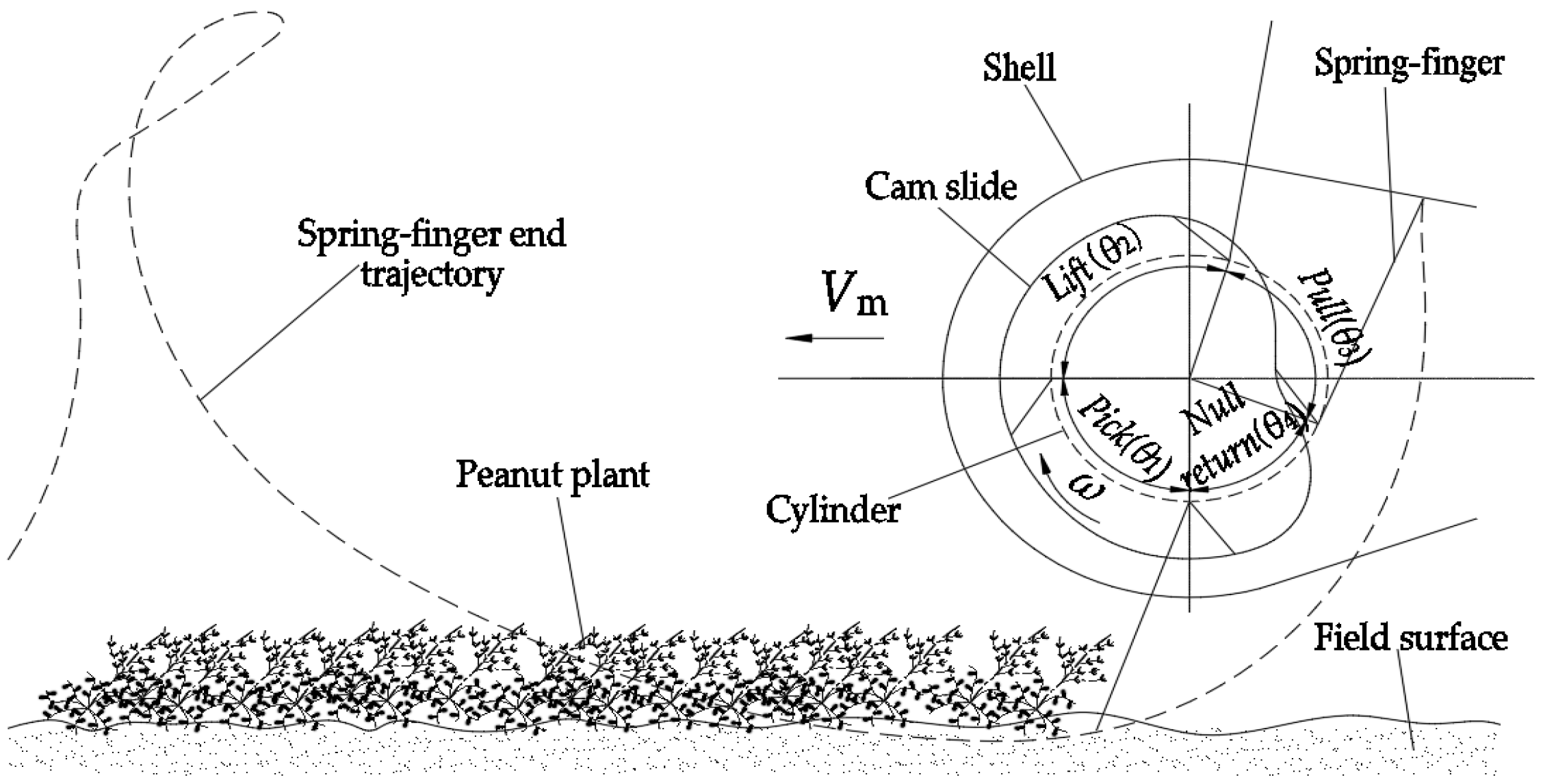
The working principle of the spring-finger cylinder pickup device is shown in Figure 2. When the pickup device moves forward with the harvester, as the swing law of the spring-finger is controlled by the cam slide, the spring-finger and the cylinder rotate around the central shaft, but also relative to the spring-finger shaft, which periodically and repeatedly swings. The cylinder rotates once, and each spring-finger continuously completes a pickup cycle at the four stations (corresponding to the phase Angle θ1θ4) of “pick”, “lift”, “push”, and “null return” (Figure 2).

2.2. Analysis Methods

2.2.1. Pickup Area Analysis

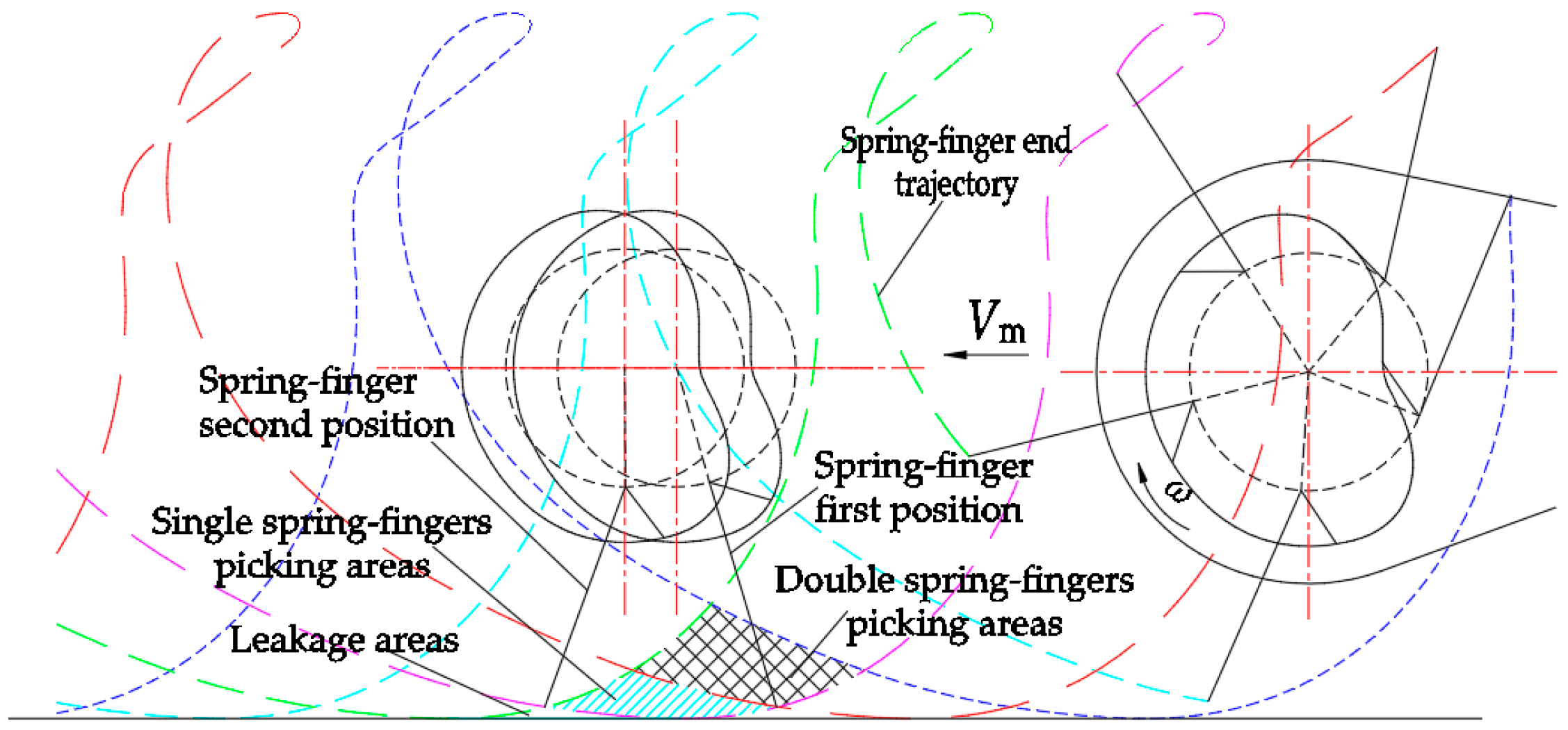
As shown in Figure 3, during the pickup operation, the trajectories of the five rows of the spring-finger end alternately form a cycloid, and two adjacent spring-fingers successively form a two spring-finger picking area, a single spring-finger picking area, and a missing picking area in the picking area.
The double spring-finger picking area is mainly composed of the back spring-finger swing area in the null return station and the front row spring-finger swing area, forming an overlapping picking area after the front row spring-finger swings in the pick station. The single spring-finger picking area is the spring-finger end trajectory formed by the transition of the single row of spring-finger from the null return station to the pick station. In this process, the spring-finger gradually swings from backward to forward. When the spring-finger tilts back, it can easily squeeze and drag the peanut plant, resulting in pod fall and/or damage. The missed picking area is the non-overlapping area formed by the arc picking trajectory of two adjacent rows of spring-finger ends. Coupled with the uneven surface, the missed picking of plants leads to pod loss [20]. Based on the above analysis, the single spring-finger picking area and the missed picking area are the main reasons for the unreasonable swing law of the spring-finger, leading to pod loss and damage.

2.2.2. Force Analysis of Peanut Plants

During the whole peanut plant picking operation, the peanut plants in the static state, due to the active force action of the spring-finger, overcome the friction between themselves and the ground, the surface of the spring-finger, and the shell, leading to action between the plants and the formation of a rigid body plane movement, which is a complex kinematic and dynamic process (which occurs in the peanut plant).
At the pick station, the peanut plant moves upward along the surface of the spring-finger, due to the internal force of the windrow and its own inertial force, and then rotates together with the spring-finger to the horizontal position by rotating with the cylinder. The motion state experiences a complex process from static, inclining to rise along the surface of the spring-finger, and rotating together with the spring-finger. Therefore, the pick station can be divided into two stages—shoveling and picking—according to whether the peanut plants and spring-finger leave the surface.
(1)
Force analysis of shoveling stage
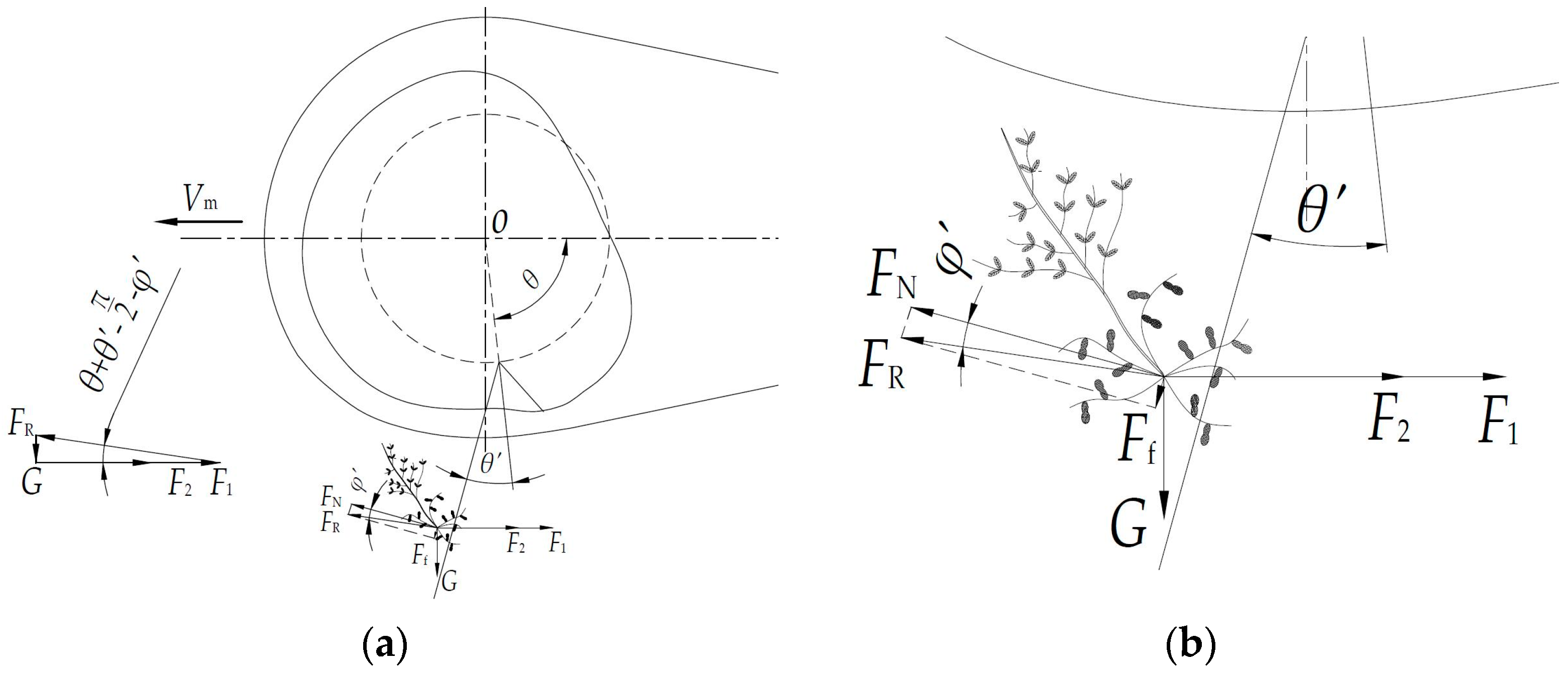
As shown in Figure 4, in the initial stage of shoveling, the picking device moves forward, the spring-finger touches the peanut plant, and it is subjected to gravity G, inertia force F1, internal force F2 of the windrow, friction force Ff, and the force FN of the spring-finger on the peanut plant. Assuming the peanut plant and the spring-finger are in equilibrium, FN and Ff are combined into the total reaction force FR, and the force vector equation and vector diagram are obtained:
In the figure, F1 is the inertia force of the peanut plant, [N]; F2 is the internal force of the windrow, [N]; G is the gravity of the peanut plant, [N]; Ff is the friction force between the spring-finger and peanut plant, [N]; FN is the force of the spring-finger on the peanut plant, [N]; FR is the total reaction force combining FN and Ff, [N]; φ′ is the frictional angle force between the spring-finger and peanut plant, [rad]; θ′ is the swing angle of spring-finger, [rad]; and θ is the rotation angle of the cylinder, [rad].
F R + F 1 + F 2 + G = 0 ,
F 1 + F 2 = G t a n ( θ + θ π / 2 φ ) .
Therefore, Formula (2) denotes the condition that the peanut plants are in equilibrium.
When F 1 + F 2 > G t a n ( θ + θ π / 2 φ ) , the peanut plant will overcome the friction and move upward along the spring-finger, and the force F2 provided by the peanut windrow is sufficient to complete the picking operation. When the cylinder rotates, the rotation angle θ increases and F1 + F2 gradually decreases. In addition, the greater the swing angle θ′ of spring-finger, the smaller the value of F1 + F2. Therefore, increasing θ and θ′ can reduce the force of picking peanut plants, and the relative front swing of the spring-finger is conducive to the picking peanut plants.
(2)
Force analysis of the picking stage
In the initial picking stage (Figure 5a,b), the centrifugal inertia force F′ acting on peanut plants was decomposed into the force Ft′ in the direction of the spring-finger and the force FN′ in the vertical direction of the spring-finger. Then, FN′, FN, and the friction force Ff were combined into the total reaction force FR. The gravity G, inertial force analysis Ft′, and total reaction force FR were obtained as F3 through a graphical method, the direction of which is outward along the spring-finger. Therefore, in the initial pick stage, peanut plants rotate together with the spring-finger and slide outward along the surface of the spring-finger.
In the figure, F′ is the centrifugal inertia force of a peanut plant, [N]; Ft′ is the direction component of the force F′, [N]; FN′ is the vertical component of the force F′, [N]; and FR is the total reaction force combining FNFN′, and Ff, [N].
With the clockwise rotation of the spring-finger (Figure 5c,d), the total reaction force FR on the peanut plant gradually shifts to the upper right of gravity G, and the peanut plant will be in equilibrium. Thus, the following vector equation can be obtained:
F R + F t + G = 0 .
According to the triangular relationship in the figure (Figure 5b):
F t s i n ( θ + θ + φ π ) = G s i n ( π / 2 φ ) , F t = G s i n ( θ + θ + φ ) c o s φ .
If F′ is positive and θ > π 2 , the following condition can be obtained:
s i n ( θ + θ + φ ) < 0 , θ + θ + φ > 3 π 2 .
Therefore, when Equation (5) is met, the total reaction FR gradually points to the upper right, and the peanut plant reaches the equilibrium state; that is, the spring-finger approaches the horizontal posture. The larger the value of θ + θ′, the easier the peanut plant is to balance. Therefore, increasing the spring-finger swing angle θ′ can help peanut plants to reach equilibrium in advance.
(3)
Force analysis of push station
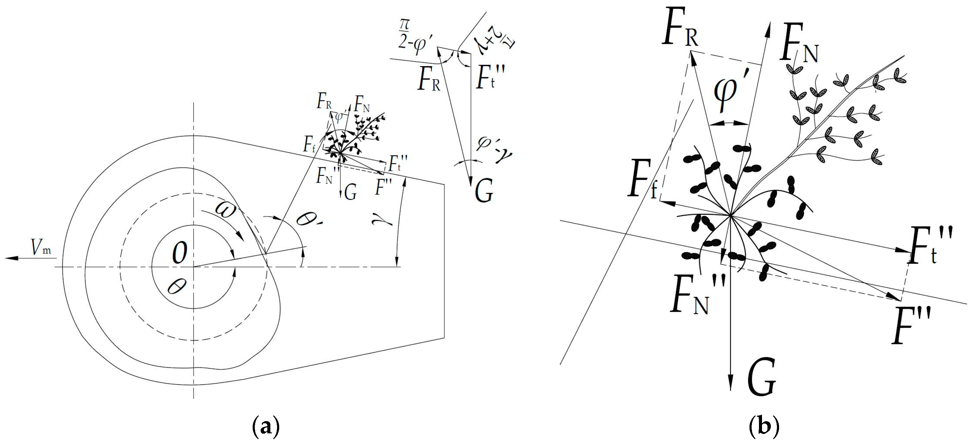
At the push station (Figure 6), the peanut plant falls to the surface of the top shell under the action of gravity, and the spring-finger rotates clockwise to push the peanut plant backward. At this time, the spring-finger force F″ is decomposed into the force Ft″ in the direction of the shell and the force FN″ in the direction of the vertical shell; again, FN″, the normal reaction FN, and friction Ff are combined into the total reaction force FR.
In the figure, F″ is the push force of the spring-finger on the peanut plant, [N]; Ft″ is the parallel force of the force F″ to the shell, [N]; FN″ is the vertical component force of the force F″ to the shell, [N]; FR is the total reaction force combining FN, FN″, and Ff, [N]; and γ is the tilt angle of the upper guard, [rad].
Assuming that peanut plants move backward at a constant speed, the force vector equation is established as follows:
F R + F t + G = 0 .
According to the force triangle diagram in Figure 6, we obtain:
F t s i n ( φ γ ) = G s i n ( π 2 φ ) , F t = G s i n ( φ γ ) c o s φ .
It can be concluded that the greater the angle γ between the top shell and the horizontal direction, the smaller the force Ft″ for the backward movement of peanut plants, and the more favorable the backward movement. In the push process, the spring-finger forward swing can increase the force Ft″, such that the peanut plant can slide smoothly along the top shell in the late push station.

2.3. Design Method

In summary, the design of the cam slide should meet three key swing laws during the picking process: (1) In the shoveling stage, the spring-finger end trajectory should be a straight line to avoid missing the picking area. As such, the height of the spring-finger end is unchanged and the spring-finger is tilted forward, causing the peanut plant to smoothly move upward along the spring-finger; (2) in the pick stage, if the spring-finger swings forward to reduce the picking height, the peanut plant can easily reach a balanced state. This will avoid peanut plants separating from spring-finger and missed picking; (3) at the end of the push station, the swing acceleration of the spring-finger decreases, which should be accelerated to push the peanut plant backward, helping the peanut plant to move smoothly down along the shell.

2.3.1. Cam Slide Center Line Design

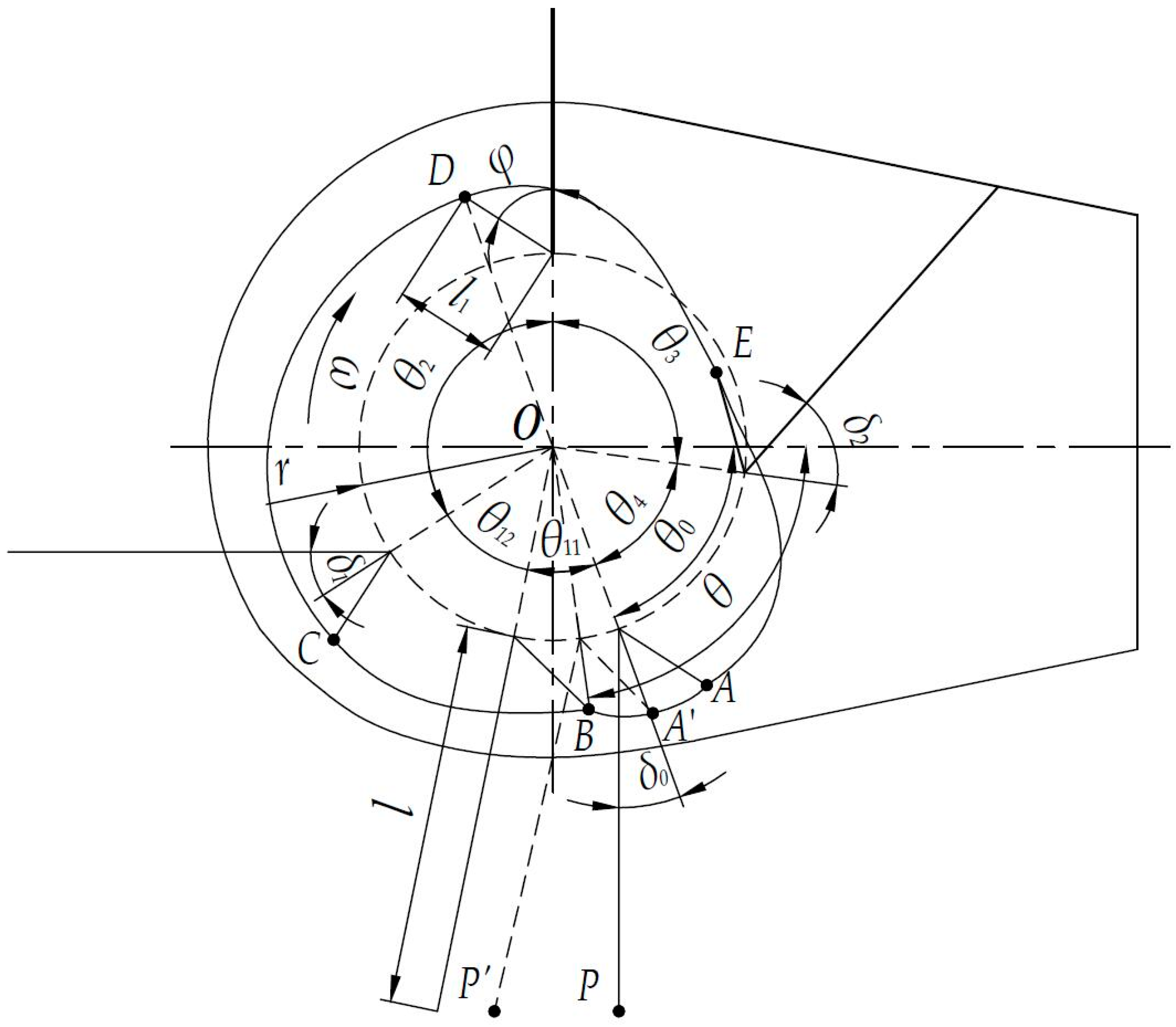
The center line of the CAM slide is a closed curve composed of four arcs, corresponding to the four pickup stations of “pick”, “lift”, “push”, and “null return” (Figure 7).
(1)
The Central Line segment A C of the cam slide is composed of two arcs A B (shoveling stage) and B C (pick stage), where the two points A and C denote the start and end points of the pick station, respectively [21];
(2)
The shoveling stage is A B . When the spring-finger rotates clockwise with the cylinder, they gradually swing back after the first swing, and the trajectory of the spring-finger end is a horizontal straight line to reduce the missing picking area formed by two adjacent rows of spring-fingers.
The initial coordinate A of the crank end in the shoveling stage is shown in Figure 7:
In the figure, δ0 is the initial swing angle of the spring-finger in the pick station, [rad]; δ1 is the initial swing angle of the spring-finger in the lift station, [rad]; δ2 is the initial swing angle of the spring-finger in the null return station, [rad]; φ is the crank angle, [rad]; θ0 is the initial angle between the cylinder radius and horizontal direction in the shovel picking stage, [rad]; θ is the rotating angle of the cylinder, [rad]; P is the end point of the spring-finger; P′ is the end point of the spring-finger after the cylinder has rotated by θ; A is the end point of the crank; A′ is the end point of crank after the cylinder has rotated by θ; l1 is the length of the crank, [mm]; l is the length of the spring-finger, [mm]; r is the radius of the cylinder, mm; A, B, C, D, and E are the beginning points of shovel picking stage, pickup picking stage, lift station, push station, and null return station, respectively; and θ11, θ12, θ2, θ3, and θ4 are the phase angles of the shovel picking stage, pickup picking stage, lift station, push station, and null return station, respectively, [rad].
{ y A = r sin ( 2 π θ 0 ) + l 1 sin ( 2 π θ 0 + ( φ ( π 2 θ 0 ) ) ) x A = r cos ( 2 π θ 0 ) + l 1 cos ( 2 π θ 0 + ( φ ( π 2 θ 0 ) )
The coordinate P of the spring-finger end is given by
{ y P = r sin ( 2 π θ 0 ) + l sin ( 3 2 π ) x P = r cos ( 2 π θ 0 ) + l cos ( 3 2 π )
The coordinates of A and P after the cylinder has turned clockwise by θ′ are given as
{ y A = r sin ( 2 π θ 0 θ ) + l 1 sin ( 3 2 π + φ θ 1 ) x A = r cos ( 2 π θ 0 θ ) + l 1 cos ( 3 2 π + φ θ 1 )
{ y P = r sin ( 2 π θ 0 θ ) + l sin ( 3 2 π θ 1 ) x P = r cos ( 2 π θ 0 θ ) + l cos ( 3 2 π θ 1 )
The horizontal height of the spring-finger end position remains unchanged after the cylinder rotates θ′ clockwise from its initial position. The relationship in Formula (12) between the cylinder angle θ′ and the spring-finger angle θ1 is obtained from the joint vertical Formulas (9) and (11), as follows:
θ 1 = arccos ( 1 2 r l cos ( θ 0 + θ 2 ) sin ( θ 2 ) )
Substituting this into Formula (8), the cam slide center line in the shoveling stage is obtained:
{ y A = r sin ( θ 0 + θ ) l 1 cos ( φ arccos ( 1 2 r l cos ( θ 0 + θ 2 ) sin ( θ 2 ) ) ) x A = r cos ( θ 0 + θ ) + l 1 sin ( φ arccos ( 1 2 r l cos ( θ 0 + θ 2 ) sin ( θ 2 ) ) )
(3)
The pick stage is B C . According to the analysis in Section 2.2.2, the front swing angle of the spring-finger is δ1, and the curve B C of the spring-finger adopts the quintic polynomial motion law for transition, such that the instantaneous swing acceleration of the spring-finger at the beginning and end of the pick stage is 0, which reduces the impact on peanut plants, avoids accumulation and pod loss, and effectively reduces the pick height on the premise that the radius of the shield remains unchanged.
(4)
In the lift station, the center line segment of the cam slide corresponds to the arc C D . The spring-finger gradually swings back when it is lifted, and the spring-finger is required to extend the longest distance from the shell at the end, which is conducive to pushing the peanut plant backward. Therefore, the motion law based on a quintic polynomial is used for the transition of C D , and the spring-finger gradually swing back to δ1.
(5)
In the push station, the center line segment of the cam slide corresponds to the D E arc, which requires the spring-finger to gradually shrink into the shell with the rotation of the cylinder, having a backward pushing effect on the peanut plant. In the process, if the angle between the spring-finger and the shell section is too small, the peanut plant is pinched. Therefore, D E also adopts the curve of the quintic polynomial motion law for transition, such that the spring-finger gradually swings back to δ2. During the pushing process, the swing angle acceleration of the spring-finger gradually increases to the maximum value and then decreases to 0, and the swing angular velocity of the spring-finger end first decreases and then increases. In the late stage of the push station, it is beneficial to push peanut plants such that they slide smoothly along the upper shell.
(6)
In the null return station, the center line segment of the cam slide is E F , requiring the spring-finger to quickly swing forward to vertical downward, and the spring-finger swings to δ0. Therefore, the quintic polynomial motion law was adopted to carry out the transition, such that there was no sudden change in the beginning and end of the swing acceleration at the null return station, which reduced the impact on peanut plants at the initial pick station.

2.3.2. Cam Slide Center Line Phase Angle Design

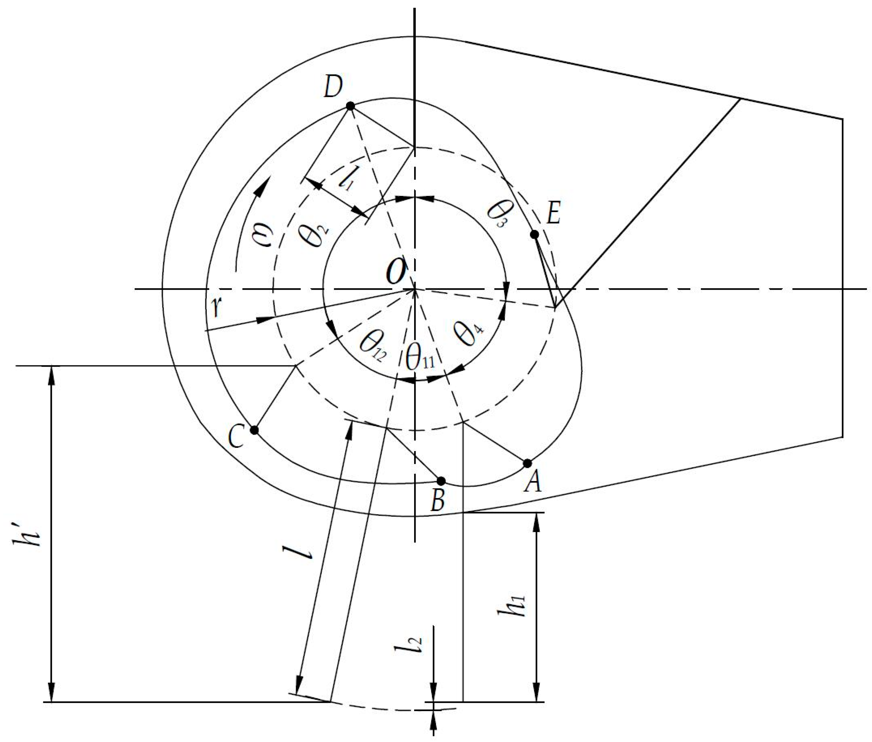
As shown in Figure 8, the trajectory of the spring-finger end is a straight line in the shoveling stage, and the maximum difference in distance, extended between the initial position of the spring-finger in the shoveling stage and the vertical direction, is denoted as l2. According to the triangular relationship shown in Figure 8, the phase angle θ11 is:
θ 11 = arccos ( r l 2 r ) + arccos ( r + l l 2 r + l )
In the figure, h′ is the picking height, mm; h1 is the height of the spring-finger in the shoveling stage, mm; and l2 is the maximum distance difference extended between the initial position of the spring-finger in the shoveling stage and the vertical direction, [mm];
Based on the existing parameters of spring-finger cylinder pickup mechanisms, the main parameters are as follows: the radius of the cylinder is r = 92.72 mm, the length of the crank is l1 = 50 mm, the length of the spring-finger is l = 183 mm, and the angle between the spring-finger and the crank is γ = 1 rad. The thickness of the peanut windrow is about 90–100 mm and, considering that the spring-finger needs to be inserted 10–20 mm when picking up, it can be determined that the height of the spring-finger in the shoveling stage is h1 > 120 mm. Therefore, choosing 6 mm for l2 and substituting it into Formula (4), we obtain θ11 = 32°.
In the picking stage, the spring-finger rotates with the cylinder and swings forward at the same time. At the end of the picking stage, the spring-finger is in a horizontal state. In order to avoid scratching between the peanut plant and the peanut windrow, the picking height h′ > 200 mm can be used to determine θ12 = 45°. At the end of the lift section, the spring-finger is in the vertical state and, at the end of the push station, the spring-finger shrinks into the shell. Based on the above analysis, the vertical and corresponding relationships between the cylinder angle, cam angle, and spring-finger swing angle were determined, as presented in Table 1.

2.4. Simulation Analysis of Pickup Mechanism

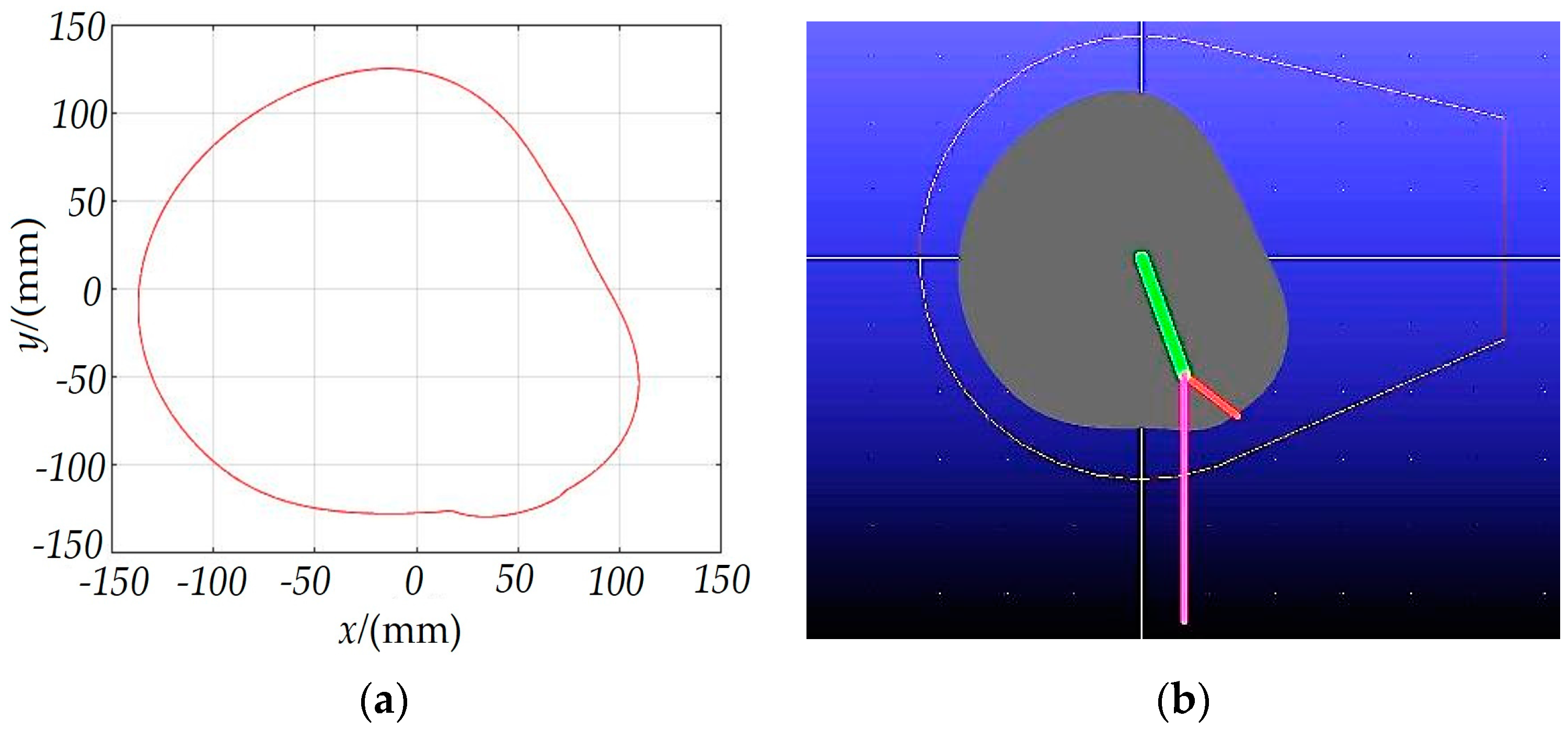
In order to verify the correctness of the theoretical derivation, kinematics and dynamics simulation analysis of the pickup mechanism was carried out. The center line of the cam slide was drawn using MATLAB and imported into ADAMS to establish the simulation model (Figure 9) [22].
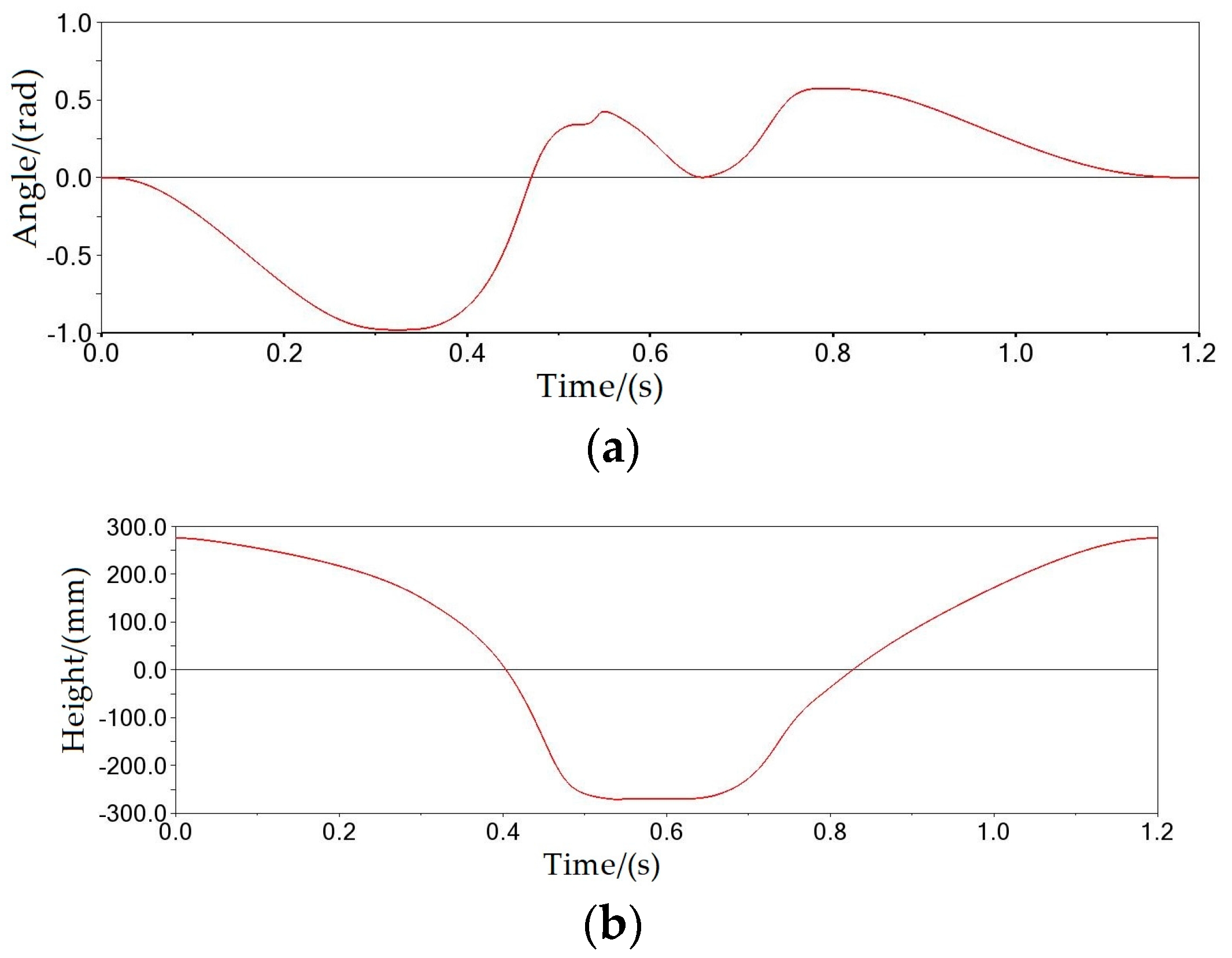
According to the working parameters of the existing peanut pickup harvester, Vm = 45 m/min, ω = 50 r/min, and a rotation period of 1.2 s were set to obtain the swing angle curve of the spring-finger (Figure 10a) and the height curve of the spring-finger end (Figure 10b).
In order to facilitate the analysis, the push station was taken as the simulation’s starting position. At this time, the spring-finger is vertical and collinear with the radius of the cylinder, and the cylinder rotates clockwise one time. As shown in Figure 10a, from 0 to 0.33 s (push station), the spring-finger gradually swings back to −0.98 rad, and gradually shrinks into the shell. From 0.33 to 0.53 s (null return position), the spring-finger quickly swings forward, from −0.98 to 0.35 rad, and the end of the spring-finger reaches its lowest location (Figure 10b). From 0.53 to 0.64 s (shoveling stage of pick station), the spring-finger end height remains unchanged, the spring-finger swings forward and then swings back, and the shoveling stage ends when the angle between the spring-finger and cylinder radius is 0 rad. From 0.64 to 0.79 s (pick station), the spring-finger swings forward to 0.58 rad. From 0.79 to 1.2 s, the swing angle of the spring-finger gradually swings back from 0.58 rad to 0, and the end of the spring-finger end reaches its highest location.
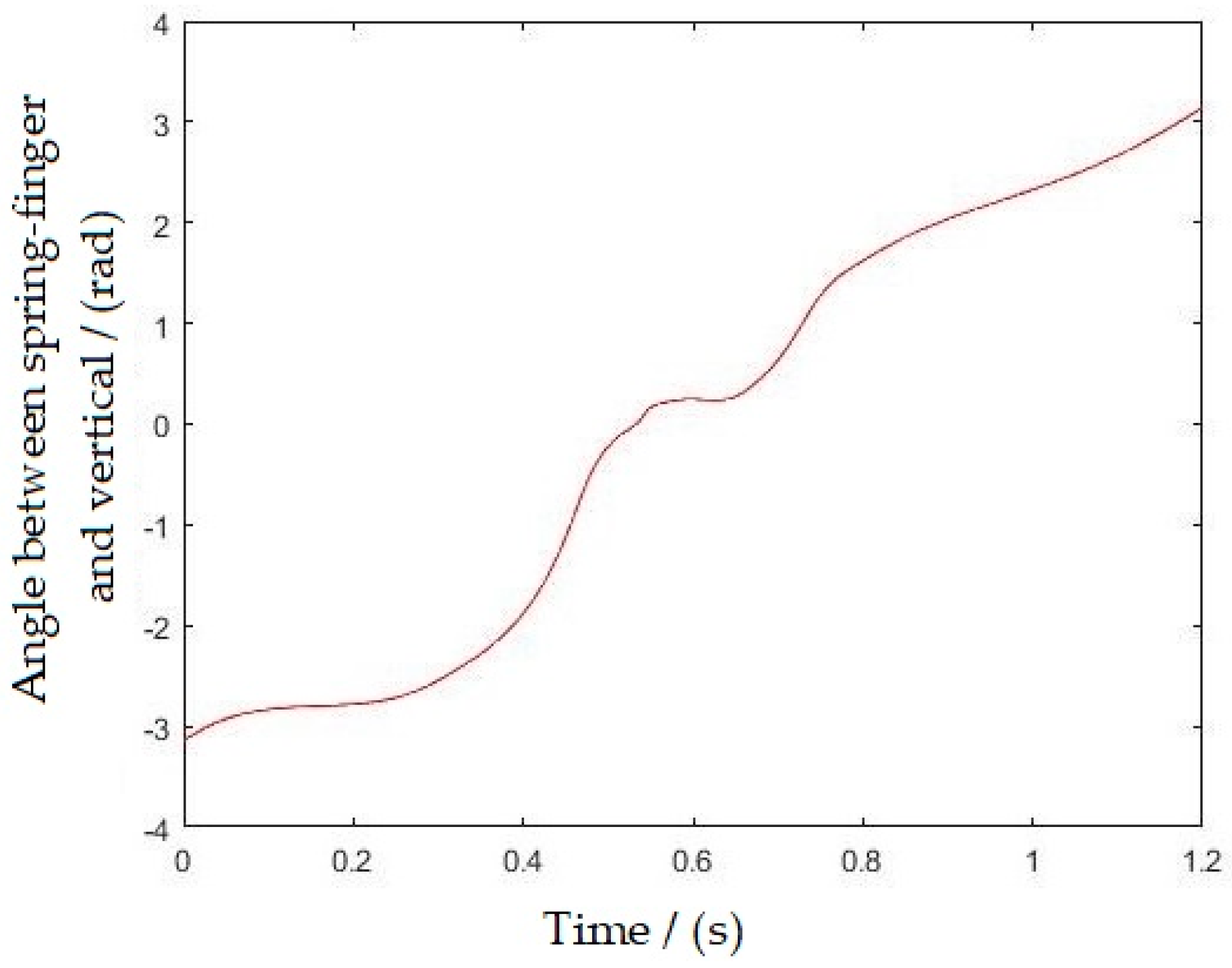
As shown in Figure 11, at 0.53 s, the angle between the spring-finger and the vertical direction is 0 rad, and the spring-finger is in a vertical state, and then gradually increases and the spring-finger tilts forward. At 0.79 s, the angle between the spring-finger and the vertical direction is 1.57 rad, the spring-finger is in a horizontal state, and the height difference between the end of the spring-finger and the lowest point is 220 mm (Figure 10b).

2.5. Pickup Area Comparative Analysis

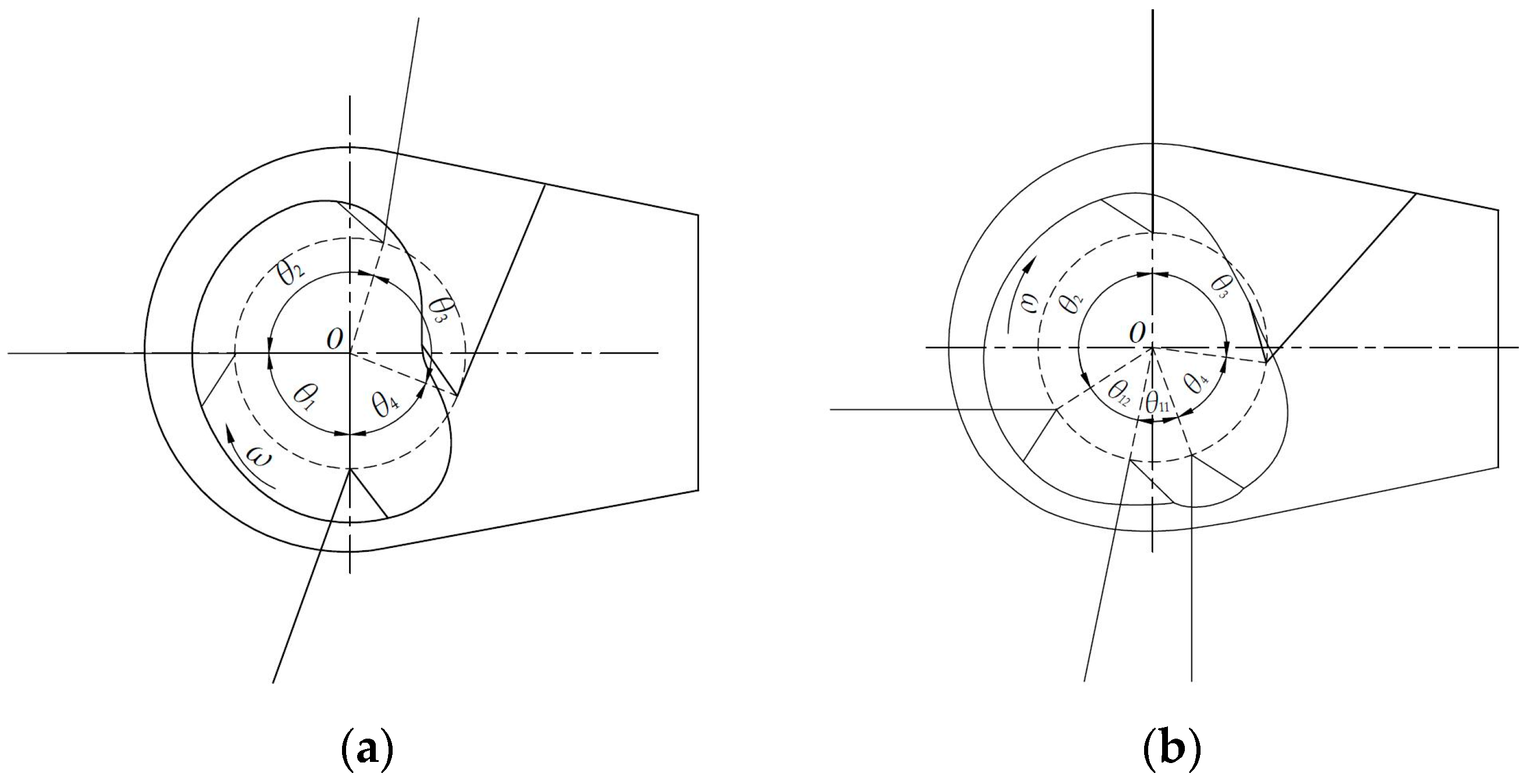
Figure 12 shows kinematic diagrams of the mechanisms before and after optimization. The main parameters of the pickup mechanism before and after optimization are presented in Table 2 [23,24]. After optimization, the utilization rate of the spring-finger is higher, the volume of the pickup device is smaller, the pickup height is lower, and the impact of the roller on the cam slide is reduced.
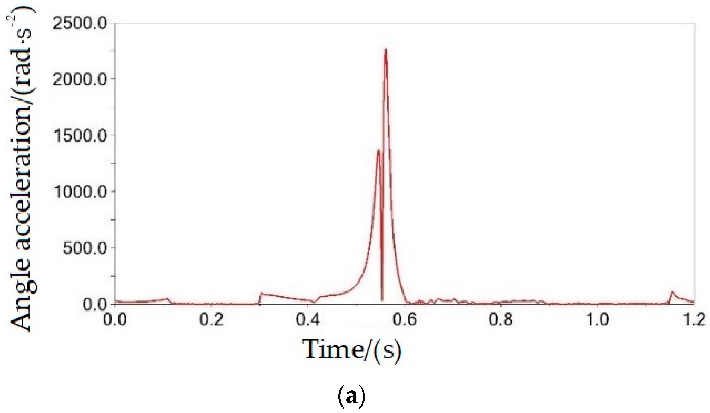
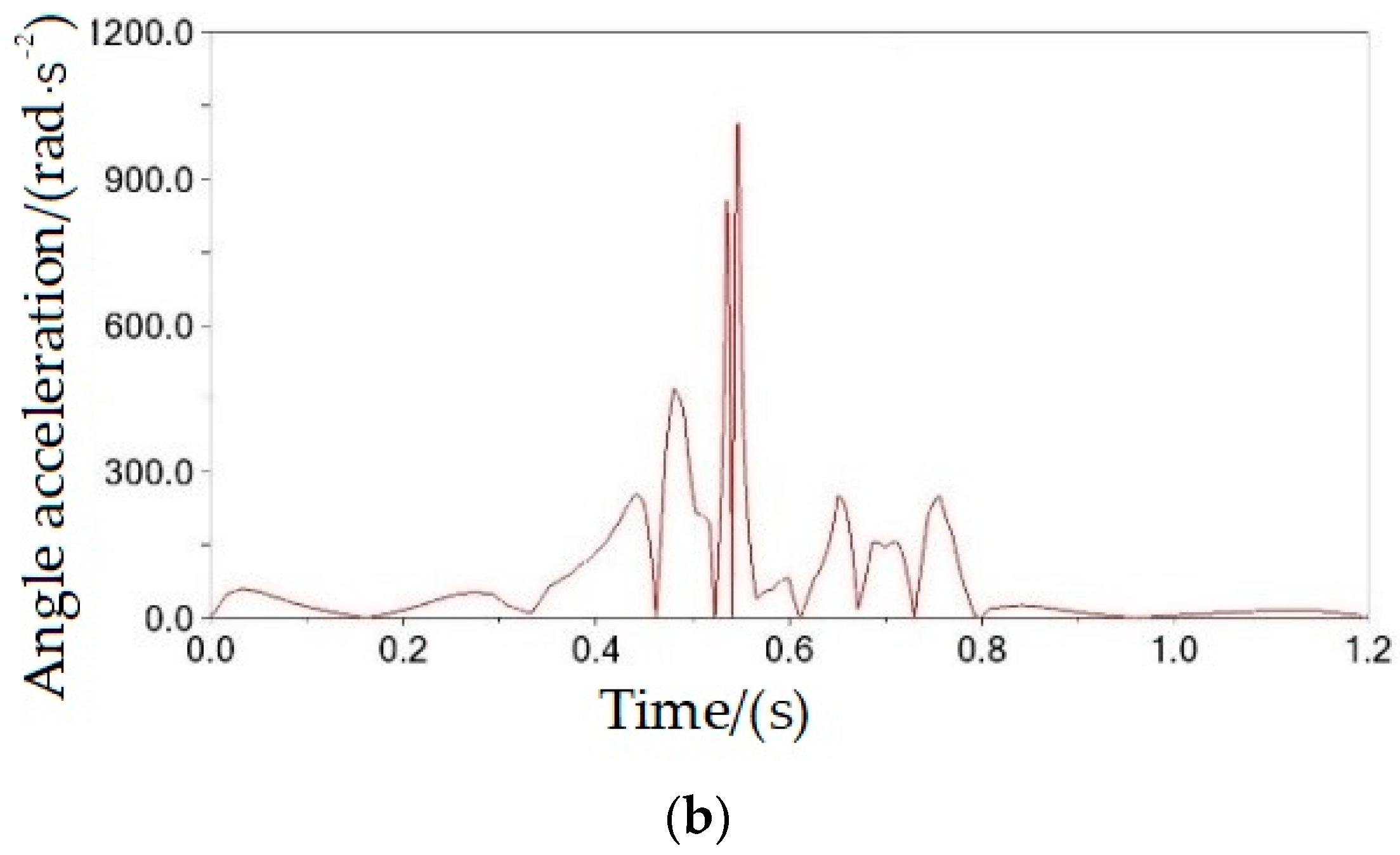
Comparing the angular acceleration of the spring-finger (Figure 13), it can be seen that the angular acceleration of the spring-finger after optimization is 1050 rad·s−2, which is much less than the 2300 rad·s−2 before optimization. The impact of the roller on the slide was smaller, and the stability of the pickup device was better.
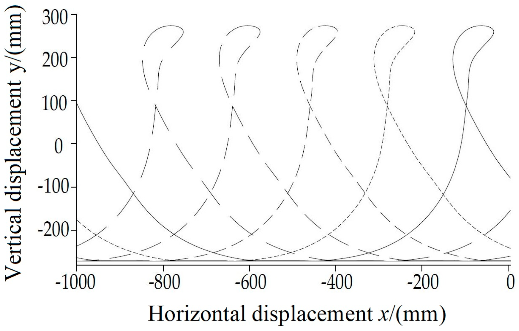
Figure 14 shows the motion trajectory of the spring-finger end when five spring-finger rows were installed on the pickup device. Table 3 compares the height and area of the missed picking area before and after optimization. After optimization, the height and area of the missed picking area were smaller, which can effectively reduce the missed picking area caused by fluctuations in the field surface.

2.6. Analysis of Pickup Parameters

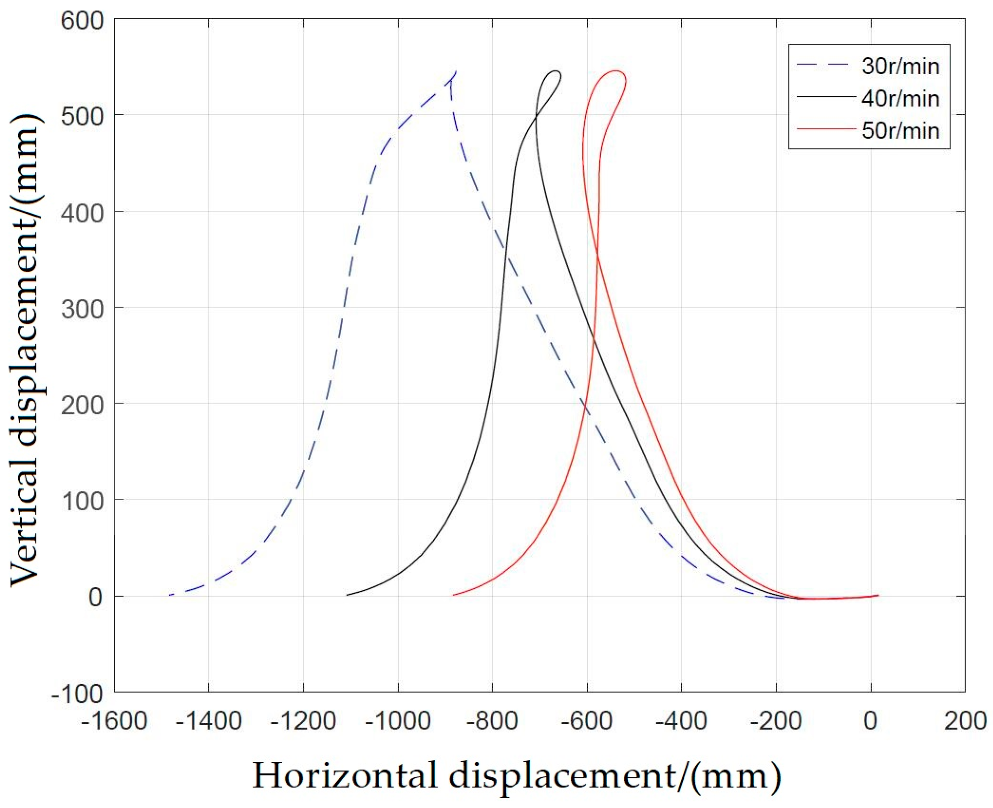
The main parameters that affect the displacement trajectory and linear velocity of the spring-finger are the length of the spring-finger, the rotation angular speed of the cylinder, the radius of the cylinder, the swing angle of the spring-finger, and the forward speed of the pickup device. In order to obtain a reasonable working parameter ratio, the influence of the rotation speed on the picking state of peanut plants was analyzed (Figure 15), and the cycloidal characteristic parameter λ was introduced.
λ = ( r + l ) ω V m ,   λ 0
When λ > 1, the upper half of the cycloid ring formed at the spring-finger end has a horizontal velocity component opposite to the forward direction of the pickup device, which is the necessary condition for the spring-finger to push the peanut plants backward.
In order to obtain a reasonable pickup speed ratio of the pickup device, it can be seen, from Formula (15) that, when the forward speed of the pickup device is set (Vm = 45 m/min), different cycloidal characteristic parameters are obtained when the ratio is varied (Table 4). The larger the cycloid feature parameter, the larger the ring formed above the spring-finger end trajectory, and the smaller the missed area formed by the spring-finger end trajectory (Figure 16).
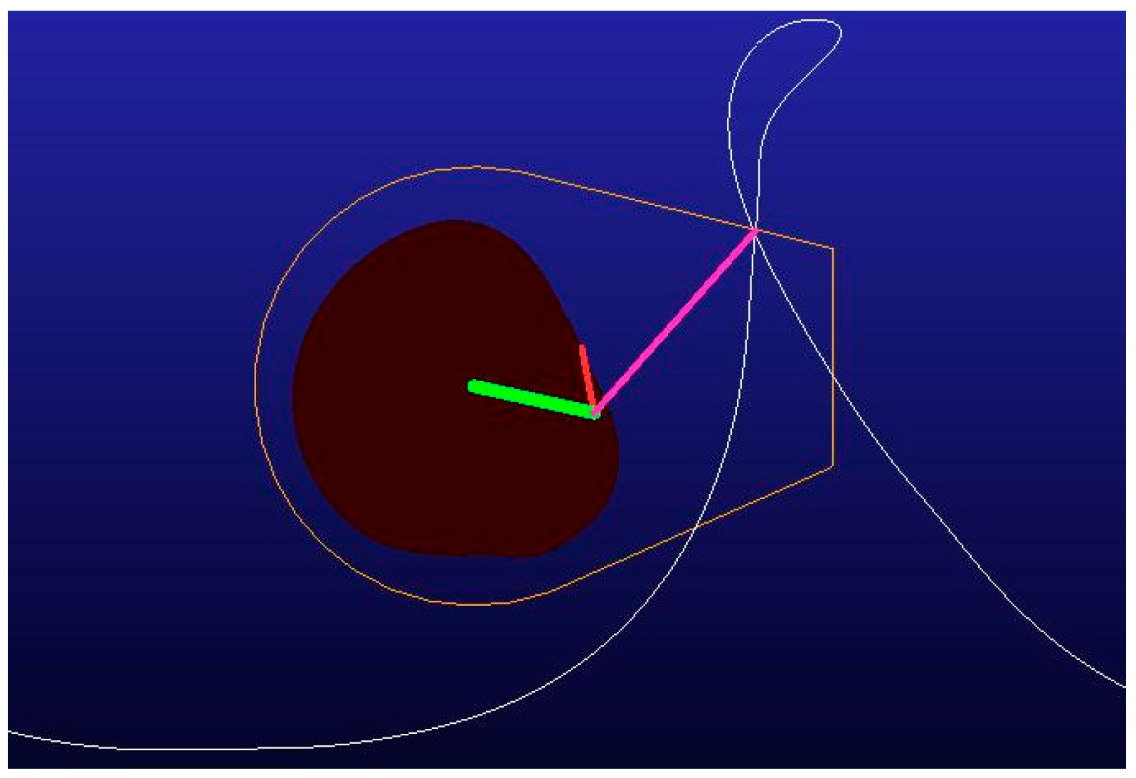
Through ADAMS motion simulation analysis, it can be seen that, when λ = 1.85, the intersection point of the ring buckle is located at the cross-section of the upper shell (Figure 17). Combined with the average size of a peanut plant, the force analysis at the pick station, and observation of the test state, the cycloid characteristic parameters were determined to be 1.7–1.8.

3. Results and Discussion

3.1. Pickup Device Performance Test

3.1.1. Test Materials and Instruments

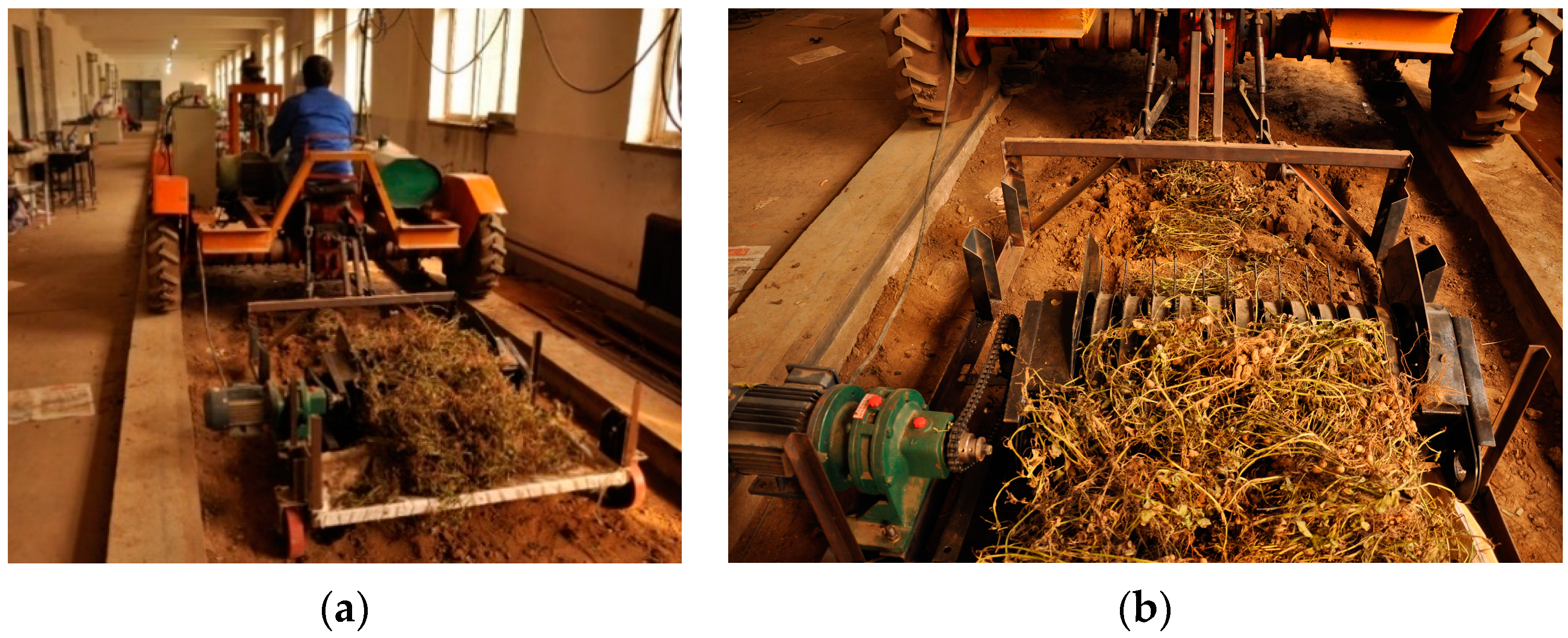
In order to verify the feasibility of the design, a prototype was designed and manufactured and pickup tests were carried out in the soil tank at the Laboratory of the College of Engineering, Shenyang Agricultural University (Figure 18). The width of the soil tank was 2 m, and the indoor temperature was 16 °C.
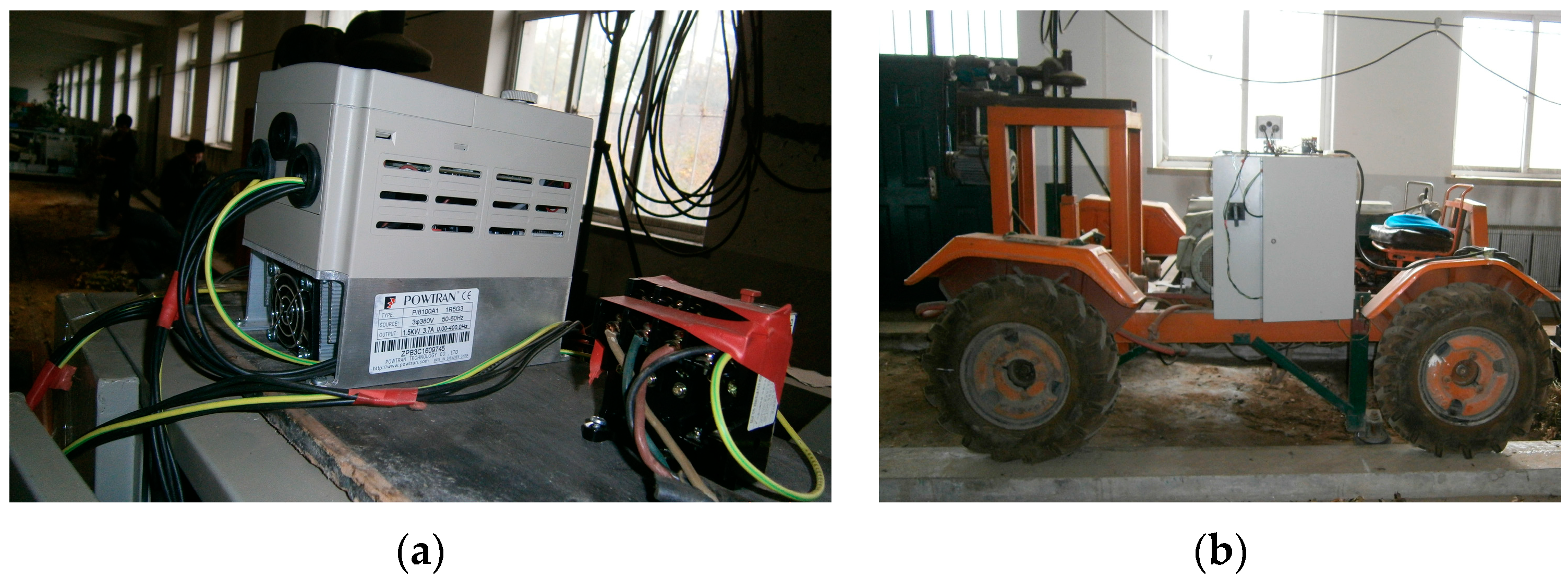
The peanut variety used in the test was Huayu 30, which had been dried in the field for 5 days. The moisture content of the peanut straw was reduced to 15–17%. Two rows of pods facing one side were formed into one bed, and the length of the peanut windrow in each test was 20 m. The main test device, the soil tank truck, had a forward speed adjustment range of 10–100 m/min, a 1.1 kW motor to provide power, and frequency converter (POWTRAN PI8100A1) speed control (Figure 19). Other test instruments and tools used included a laser tachometer (RM-722), electronic stopwatch, meter ruler, and scale [25].

3.1.2. Box–Behnken Experimental Results and Analysis

According to the relevant standards, the main test indices were determined as pickup rate and loss rate. According to the central combined test design principle considering response surface analysis (RSM) and Box–Behnken Design (BBD), the forward speed of the pickup, the rotating speed of the cylinder, and the depth of the end of the spring-finger were selected as the test factors, and the test design of three factors at three levels (Table 5) was developed. A total of 17 groups were repeated three times for each group. The test scheme and results are shown in Table 5. X1, X2, X3 are factor-coded values [26,27].
A total of 17 groups of tests were carried out, and each group was repeated three times to obtain the average value. The results of the test are provided in Table 6.
(1)
Establishment of regression model and significance test
The Design-expert 12.0 software was used to carry out multiple regression fitting analysis on the data in Table 6, and a quadratic polynomial response surface regression model was established for the effects of pickup rate and loss rate on the three independent variables, namely, forward velocity of the pickup, cylinder rotation speed, and depth of the spring-finger in the field. The model was established as follows:
Y 1 = 93.31 0.065 X 1 + 0.285 X 2 0.29 X 3 + 0.0025 X 1 X 2 0.002 X 1 X 3 + 0.0025 X 2 X 3 0.0015 X 1 2 0.004 X 2 2 0.075 X 3 2
Y 2 = 3.52 0.31775 X 1 + 0.36625 X 2 0.11925 X 3 + 0.00025 X 1 X 2 0.002 X 1 X 3 + 0.00125 X 2 X 3 0.00285 X 1 2 0.0039 X 2 2 0.00465 X 3 2
As can be seen from Table 7, the p-values of both the pickup rate and the loss rate were less than 0.01, indicating that the influence of the two models is extremely significant. The p-values of Lack of Fit were 0.5602 and 0.1776, respectively (both greater than 0.05), indicating that the two models fit well within the range of test parameters. The determination coefficients R2 were 0.9779 and 0.9849, respectively, indicating that more than 97% of the response values can be explained by these two models. As such, the model can effectively predict the working parameters of the pickup mechanism.
As shown in Table 7, the depth of the spring-finger in the field has a very significant effect on the picking rate (p < 0.01), and the order of influence of various factors on the pickup rate was as follows: the depth of the spring-finger in the field > the forward velocity of the pickup > the cylinder rotation speed. The first and quadratic terms of the depth of the spring-finger in the field, the first terms of the forward velocity of the pickup, and the first and quadratic terms of the cylinder rotation speed all reached significant levels (p < 0.05). The remaining non-significant terms were eliminated, and the regression model of each factor for the index Y1 was simplified as follows:
Y 1 = 93.31 0.065 X 1 + 0.285 X 2 0.29 X 3 0.004 X 2 2 0.075 X 3 2
As shown in Table 7, the depth of the spring-finger in the field has a significant effect on the loss rate (p < 0.01), and the order of influence of various factors on the loss rate was as follows: the depth of the spring-finger in the field > the forward velocity of the pickup > the cylinder rotation speed. The first and quadratic terms of the depth of the spring-finger in the field, the first and quadratic terms of the forward velocity of the pickup, and the first and quadratic terms of the cylinder rotation speed, as well as the interaction terms of the forward velocity of the pickup and the depth of the spring-finger in the field all reached significant levels (p < 0.05). The remaining non-significant terms were eliminated, and the regression model of each factor for the indicator Y2 was simplified as follows:
Y 2 = 3.52 0.31775 X 1 + 0.36625 X 2 0.11925 X 3 0.002 X 1 X 3 0.00285 X 1 2 0.0039 X 2 2 0.00465 X 3 2

3.1.3. The Impact of Interaction Factors on Performance

According to the test results in Table 7, the interaction effects of the depth of the spring-finger in the field, the forward velocity of the pickup, and the cylinder rotation speed on each performance index were obtained, and the response surface diagram was drawn using the Design-Expert 12.0 software:
(1)
Influence of interaction factors on picking rate
The response surface diagram of the influence of interactive factors on the picking rate is shown in Figure 20. From Figure 20a, it can be seen that reducing the forward velocity of the pickup and the cylinder rotation speed is conducive to improving the picking rate. It can be seen, from Figure 20b, that increasing the depth of the spring-finger in the field and decreasing the forward velocity can improve the picking rate. It can be seen, from Figure 20c, that increasing the depth of the spring-finger in the field and decreasing the cylinder rotation speed can improve the picking rate.
(2)
Influence of interaction factors on loss rate
A response surface diagram of the influence of interactive factors on the loss rate is shown in Figure 21. As can be seen from Figure 21a, reducing the forward velocity of the pickup and the cylinder rotation speed can help to reduce the loss rate, and the loss rate was the lowest when the cylinder rotation speed was about 48 r/min. From Figure 21b, it can be seen that the loss rate can be reduced by increasing the depth of the spring-finger in the field and reducing the forward velocity of the pickup. It can be seen, from Figure 21c, that the loss rate can be reduced by increasing the depth of the spring-finger in the field and reducing the rotating speed of the cylinder.

3.1.4. Working Parameters Optimization

Based on a pair of the optimization module solutions in the Design-Expert 12.0 software, the optimal combination of working parameters was obtained as follows: the pickup forward speed Vm was 48.0 m/min, the cylinder rotation speed N was 50 r/min, and the depth of the spring-finger end H was −16.8 mm, corresponding to a picking rate of 99.21% and a loss rate of 1.79%.
In order to further verify the correctness of the optimized working parameters of the pickup device, a set of parameters close to the optimized values was selected; in particular, the pickup forward speed Vm was 48.0 m/min, the cylinder rotation speed N was 50 r/min, and the depth of the spring-finger end H was 17 mm. The length of the peanut windrow spread was 20 m. The average value of the test was taken for 10 replicates, and the test indices are shown in Table 8. The average picking rate and loss rate were 99.19% and 1.84%, respectively. The actual test values are close to the theoretical analysis values, and better than the values specified in the industry standard NY/T502-2016 [28].

3.2. Discussion

The pickup device is a key component of the pickup system of a peanut combine harvester, the performance of which not only directly affects the peanut plant picking rate but also affects the pod loss rate. Compared with other traditional pickup devices, the spring-finger cylinder pickup device is small and the spring-finger can swing relative to the cylinder, allowing it to complete the complex pickup action with better pickup performance and adaptability; as such, it is widely used in small- and medium-sized peanut harvesters.
The traditional spring-finger cylinder pickup device mostly resembles the forage pickup device, and its core parts (cam slide) mostly have a “heart-“ or “bean-shaped” structure, which can easily lead to “stack” and “loss picking” of peanut plants during the picking operation, resulting in pod loss. Therefore, traditional spring-finger cylinder pickup devices are not suitable for the picking of erect peanut plants in China. In recent years, many experts and scholars have studied spring-finger cylinder pickup devices, but most of them have optimized the cam slide design to reduce the impact of the roller on the slide, or obtained optimal working parameters through testing. However, in these studies, in order to reduce the missed area formed by the adjacent spring-finger when increasing the rotating speed of the cylinder, the impact of the spring-finger on pod was increased, and the pod loss seriously increased.
Compared with previous research, based on the principle of close integration of agricultural machinery and techniques, this study analyzed the state forces on peanut plants during the picking operation, in order to design a reasonable swing law of the spring-finger, and allowing the cam slide to be designed using an inverse principle. Through establishing a mathematical model of the cam slide, the design accuracy was improved and the impact of the roller on the cam slide was reduced. The proposed pickup design can lower the height at which peanut plants are picked up, thus reducing the leakage of peanut plants and pod losses. Through experimentation, the designed pickup was validated to efficiently increase the picking rate and decrease the loss rate. Therefore, it is expected to provide new design ideas and methods, having great significance for the design of picking devices for peanut combine harvesters.

4. Conclusions

In this study, the causes of peanut plant “stack” and “loss picking” phenomena were determined through analysis of the picking area and the forces experienced by peanut plants during the picking process. On this basis, the swing law of the spring-finger in each picking stage was designed, the center line of the cam slide is designed, and reverse optimization-based design of a spring-finger cylinder peanut pickup mechanism was realized. In this process, the mathematical model of the cam slide was analyzed and deduced, and the model of the pickup mechanism was established using MATLAB and ADAMS. This allowed for the accuracy of the design of the pickup mechanism and the swing law of the spring-finger to be improved. It was experimentally verified that the above research method is feasible, such that this study provides both a theoretical and experimental basis for the research and development of pickup devices for combine harvesters designed for peanut and other similar crops. The main conclusions of the study are as follows:
(1)
Through an analysis of the picking area, as well as the force and motion states of peanut plants, the main mechanism parameters affecting the motion state were determined, and picking attitude and swing laws for the spring-finger were designed.
(2)
The optimal design of the cam slide was determined, and motion simulation analysis of the pickup mechanism was carried out using the ADAMS software. Consequently, the range of the cycloid characteristic parameter was determined to be 1.7–1.8.
(3)
A prototype was manufactured and a soil tank test was carried out. Through comprehensive multi-index response surface test analysis, the optimal working parameters of the pickup device were obtained: The forward speed Vm of the pickup is 48.0 m/min, the rotating speed N of the cylinder is 50 r/min, and the depth of the end of the spring-finger is −16.8 mm. Under this parameter combination, the recovery rate is 99.21% and the loss rate is 1.79%, and the real value was found to be close to the theoretical value.
In the future, the research and development of pickup devices should be based on the close combination of agricultural machinery and agronomy, and The large width and small volume pickup device was developed to adapt to large peanut combine harvesters, and advanced design methods should be used to optimize the design and improve the adaptability and standardization of the pickup device, thus achieving efficient picking operations with low loss rates, and further promoting the mechanization of peanut harvesting.

Author Contributions

Conceptualization, L.G. and Z.L.; Methodology, L.G. and Z.L.; Software, T.X.; Writing—original draft, T.X. All authors have read and agreed to the published version of the manuscript.

Funding

This research was funded by the National Key Research and Development Project Plan of China (Program No. 2016YFD0702102), and the National Natural Science Foundation of China (Program No. 51575367).

Institutional Review Board Statement

Not applicable.

Informed Consent Statement

Not applicable.

Data Availability Statement

Data are contained within the article.

Conflicts of Interest

The authors declare no conflict of interest.

References

  1. Lu, R.; Gao, L.X.; Chen, C.; Butts, C.L. Characteristics of peanut hulling and processing technology in the United States and inspiration. Trans. Chin. Soc. Agric. Eng. 2019, 35, 287–298. [Google Scholar]
  2. Hu, B.C. Design and Testing of the Long Seeding Transport and Collection Device for Peanut Picking and Harvesting Machines. Master’s Thesis, Henan Agriculture University, Zhengzhou, China, 2023. [Google Scholar]
  3. Xu, T.; Liu, Z.X.; Gao, L.X.; Shen, Y.Z. Technology research status and development of peanut pickup device of China and the United States. J. Shenyang Agric. Univ. 2023, 54, 372–384. [Google Scholar]
  4. Chen, Z.Y.; Gao, L.X.; Chen, C.; Butts, C.L. Analysis on technology status and development of peanut harvest mechanization of China and the United States. Trans. Chin. Soc. Agric. Mach. 2017, 48, 1–21. [Google Scholar]
  5. Guan, M.; Shen, Y.Z.; Gao, L.X.; Zhao, B.Q.; Liu, W.W. Mechanical properties of peanut peg after digging and drying. Trans. Chin. Soc. Agric. Eng. 2014, 30, 87–93. [Google Scholar]
  6. Liu, Z.X.; Yu, Y.Q.; Wang, J.; Kang, Z.W.; He, F.Y.; Gao, L.X. Numerical Simulation and Optimization of Peanut Sheller Air–Screen Cleaning Device. Agriculture 2023, 13, 1997. [Google Scholar] [CrossRef]
  7. Lu, R.; Gao, L.X.; Liu, Z.X.; Yang, D.X. Development and Prospect of Technology on Peanut Sheller of China. J. Shenyang Agric. Univ. 2019, 50, 631–640. [Google Scholar]
  8. Gao, L.X.; Chen, Z.; Charles, C.; Butts, C.L. Development course of peanut harvest mechanization technology of the United States and enlightenment to China. Chin. Soc. Agric. Eng. 2017, 33, 1–9. [Google Scholar]
  9. Wang, G.Q.; Yu, Q.; Bu, Y.L.; Yu, D.N.; Wang, C.M. Design of Pickup Baler and Dynamic Simulation of Pickup Roller. Trans. Chin. Soc. Agric. Mach. 2001, 32, 59–61. [Google Scholar]
  10. Yuan, C.Y.; Diao, P.S.; Zhang, D.L. Design and Motion Simulation of Spring-finger Cylinder Pickups. J. Agric. Mech. Res. 2011, 33, 73–76. [Google Scholar]
  11. Wang, W.M.; Wang, C.G. Parameter Analysis and Simulation of Spring-finger Cylinder Pickup Collection. Trans. Chin. Soc. Agric. Mach. 2012, 43, 82–89. [Google Scholar]
  12. Yu, Z.H.; Wang, W.M.; Liu, M.; LI, L.; Cui, H.M. Experiment on Performance of Spring-finger Cylinder Pickup Collector. Trans. Chin. Soc. Agric. Mach. 2017, 48, 106–112. [Google Scholar]
  13. Xu, T.; Shen, Y.Z.; Gao, L.X.; Zhang, X.D.; Lv, C.Y.; Liu, Z.X. Spring-finger Peanut Pickup Mechanism Based on Two-stage Harvest. Trans. Chin. Soc. Agric. Mach. 2016, 47, 90–97+111. [Google Scholar]
  14. Xu, N.; Wang, D.W.; Shang, S.Q.; He, X.N.; Zhang, J.M.; Ma, N.; Gao, Z.H. The Optimum Design and Kinematics Analysis of the Picking device of Peanut Combine Harvester. J. Agric. Mech. Res. 2021, 43, 128–132. [Google Scholar]
  15. Yao, L.J.; Hu, Z.C.; Wang, S.Y.; Cao, M.Z.; Yu, Z.Y.; Wang, B. Experiment and Parameters Optimization for Pickup Mechanism of Peanut Harvester. J. Agric. Mech. Res. 2017, 12, 112–118+129. [Google Scholar]
  16. Wang, B.; Gu, W.F.; Yu, Z.Y.; Cao, M.Z.; Wang, M.T.; Hu, Z.C. Design and Experiment of Full-feed Picking-up Mechanism of Axial-now Peanut Harvester. Trans. Chin. Soc. Agric. Mach. 2020, 51, 132–141+169. [Google Scholar]
  17. Wang, S.Y.; Hu, Z.C.; Xu, H.B.; Cao, M.Z.; Yu, Z.Y.; Peng, B.L. Design and test of pickup and conveyor device for full-feeding peanut pickup harvester. Chin. Soc. Agric. Eng. 2019, 35, 20–28. [Google Scholar]
  18. Chen, Y.Q.; Hu, Z.C.; Wang, S.Y.; Cao, M.Z.; Xu, H.B.; Wang, G.P.; Yan, J.C. Design and experiments of pickup device of peanut harvester after cutting peanut straws. Chin. Soc. Agric. Eng. 2020, 36, 1–8. [Google Scholar]
  19. Xu, T.; Liu, Z.X.; Gao, L.X. Design and Experiments for Shovel-finger and Cylinder Peanut-Picking Device. Eng. Agrícola 2023, 43, e20220174. [Google Scholar] [CrossRef]
  20. Xu, T.; Shen, Y.Z.; Gao, L.X.; Liu, Z.X.; Zhang, X.D.; Lv, C.Y. Dynamic Simulation Analysis of Spring-finger Cylinder Peanut Pickup Mechanism. J. Shenyang Agric. Univ. 2016, 47, 192–198. [Google Scholar]
  21. Xu, T.; Liu, Z.X.; Gao, L.X.; Liang, G.P. Design and optimization of crank-slide type spring-finger cylinder peanut pickup mechanism. Chin. Soc. Agric. Eng. 2024, 40, 64–73. [Google Scholar]
  22. Liang, G.P. Design and Experimental Study on the Peanut Pickup Device with Shovel Tooth and Two Cylinders. Master’s Thesis, Jilin Agriculture University, Changchun, China, 2023. [Google Scholar]
  23. Hao, J.J.; Zhu, Z.M.; Li, L.; Li, J.C.; Zhao, X.S.; Zhao, J.G. Design and Experiment of Traction Peanut Secondary Harvester. J. Hebei Agric. Univ. 2023, 46, 110–120. [Google Scholar]
  24. Guo, P.; Shang, S.Q.; Wang, D.W.; He, X.N.; Xu, N.; Liu, J.Q.; Yang, L.; Dong, M.M. Design and Test of a Trailed Peanut Picking and Harvesting Maclliner. Trans. Chin. Soc. Agric. Mach. 2021, 12, 92–97. [Google Scholar]
  25. Xu, T.; Liu, Z.X.; Gao, L.X.; Liang, G.P.; He, F.Y.; Yang, D.; Li, H. Picking Dynamic Analysis and Experiment of Shovel-finger and Finger Roller Peanut Pickup Device. J. Shenyang Agric. Univ. 2024, 55, e20220174. [Google Scholar]
  26. Gao, L.X.; Liang, G.P.; Cai, Y.L.; Feng, W.Z.; Yang, Y.Z.; Liu, J.G.; Yang, J. Pickup Device with Shovel Teeth and Double Cylinders for The Bunch of Peanuts. Chin. Soc. Agric. Eng. 2024, 40, 13–22. [Google Scholar]
  27. Wang, S.Y.; Hu, Z.C.; Wu, F.; Yu, Z.Y.; Cao, M.Z.; Gao, X.M. Modeling and experiment of feeding rate for full-feed peanut pickup harvester. Chin. Soc. Agric. Eng. 2019, 35, 29–36. [Google Scholar]
  28. NY/T502~2016; Operating Quality for Peanut Harvesters. The Ministry of Agriculture of the People’s Republic of China: Beijing, China, 2016.
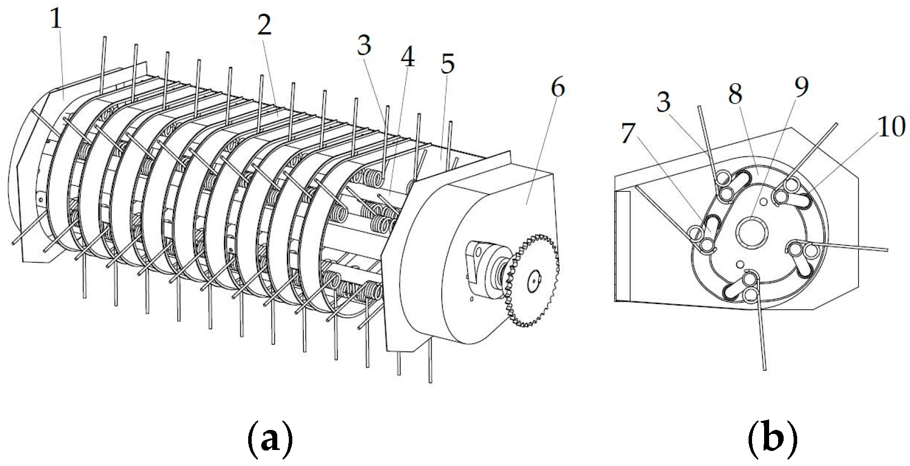
Figure 1. Structural diagram of spring-finger cylinder pickup collector: 1. Left side plate; 2. shell; 3. spring-finger; 4. spring-finger shaft; 5. back plate; 6. right side plate; 7. crank; 8. cam slide; 9. center shaft; 10. roller. (a) Pickup device axonometry; (b) pickup device cross-section.
Agriculture 14 01459 g001
Figure 2. Working principle of pickup device.
Agriculture 14 01459 g002
Figure 3. Picking locus of the spring-fingers.
Agriculture 14 01459 g003
Figure 4. Force analysis of peanut plant in shovel picking stage. (a) Force analysis; (b) local force analysis.
Agriculture 14 01459 g004
Figure 5. Force analysis of peanut plant picking. (a) Pick stage initial force analysis; (b) pick stage initial local force analysis; (c) pick stage later force analysis; (d) pick stage later local force analysis.
Agriculture 14 01459 g005
Figure 6. Force analysis of push stage. (a) Force analysis; (b) local force analysis.
Agriculture 14 01459 g006
Figure 7. Cam slide centerline.
Agriculture 14 01459 g007
Figure 8. Phase angle of the shoveling stage.
Agriculture 14 01459 g008
Figure 9. Mechanism simulation model. (a) MATLAB 2016 model; (b) ADAMS 2020 model.
Agriculture 14 01459 g009
Figure 10. Swing angle and height of spring-finger. (a) Swing angle of spring-finger; (b) end height of spring-finger.
Agriculture 14 01459 g010
Figure 11. Angle between spring-finger and vertical direction.
Agriculture 14 01459 g011
Figure 12. Comparison of the pickup mechanism. (a) Before optimization; (b) after optimization.
Agriculture 14 01459 g012
Figure 13. Swing angle acceleration of spring-finger. (a) Before optimization; (b) after optimization.
Agriculture 14 01459 g013aAgriculture 14 01459 g013b
Figure 14. End motion of spring-finger.
Agriculture 14 01459 g014
Figure 15. Cycloidal characteristic parameters.
Agriculture 14 01459 g015
Figure 16. Displacement locus of the end of spring-finger at different cylinder rotational velocities.
Agriculture 14 01459 g016
Figure 17. Testing of cycloidal characteristic parameter λ using ADAMS.
Agriculture 14 01459 g017
Figure 18. Peanut pickup test in soil tank. (a) Panoramic operation; (b) local operation.
Agriculture 14 01459 g018
Figure 19. Main test equipment. (a) Frequency converter; (b) soil tank truck.
Agriculture 14 01459 g019
Figure 20. Influence of interactive factors on picking rate.
Agriculture 14 01459 g020
Figure 21. Influence of interactive factors on loss rate.
Agriculture 14 01459 g021
Table 1. Cam motion law.
StationCylinder Rotation Angle θ/radCam Rotation Angle β/radSpring-Finger Swing Angle δ/rad
Shovel picking stage of pick station [ 0 , 32 π 180 ] [ 0 , 25 π 180 ] Gradual swing back to 0
Picking stage of pick station [ 32 π 180 , 77 π 180 ] [ 25 π 180 , 82 π 180 ] Gradual swing forward to 33 π 180
Lifting station [ 77 π 180 , 200 π 180 ] [ 82 π 180 , 194 π 180 ] Gradual swing back to 0
Pulling station [ 200 π 180 , 298 π 180 ] [ 194 π 180 , 278 π 180 ] Gradual swing back to 56 π 180
Null swing station [ 298 π 180 , 2 π ] [ 278 π 180 , 2 π ] Gradual swing forward to 20 π 180
Table 2. Parameters of spring-finger cylinder pickup collector.
Parameters of the Pickup MechanismValues
Before OptimizationAfter Optimization
Crank length L1/mm50.00050.000
Crank angle φ/rad1.0001.000
Top guard dip angle γ/rad0.2980.298
Cylinder radius r/mm99.22092.720
Spring-finger length L/mm203.050183.200
Spring-finger picking length L/mm130.000126.000
picking height h2/mm305220
shell radius/mm180.000165.000
Table 3. Rows of circumferential direction spring-finger and leakage heights and areas.
Spring-Finger RowsBefore OptimizationAfter Optimization
Loss Height/mmLose Areas/mm2Loss Height/mmLoss Areas/mm2
326.7241010.81686.24
415.210154.67256.71
511.35131.88102.35
Table 4. Cycloid characteristic parameters.
Forward Velocity (m/min)Cylinder Rotation Speed (r/min)Cycloid Characteristic Parameters λ
45301.16
401.54
501.92
Table 5. Experiment factors and levels of response surface analysis.
LevelForward Velocity X1 (m/min)Cylinder Rotation Speed X2 (r/min)Depth of Spring-Finger in Field X3 (mm)
−13540−20
04550−10
155600
Table 6. Experimental plan and results of response surface method.
ItemsX1X2X3Picking Rate Y1/%Loss Rate Y2/%
1−1−1099.61.5
21−1097.82.2
3−11098.61.9
411097.82.5
5−10−199.31.5
610−198.81.6
7−10197.82.2
810196.53.1
90−1−199.51.8
1001−198.42.7
110−1196.83.1
1201196.73.5
1300099.32
1400098.81.9
1500099.21.8
1600098.82
1700098.91.9
Table 7. Analysis of combination experiment data.
SourcePicking Rate Y1/%Loss Rate Y2/%
Sum of SquaresdfFpSum of SquaresdfFp
Model15.47934.37<0.00015.57950.69<0.0001
X12.42148.40.00020.66154.140.0002
X20.6112.10.01030.5140.940.0004
X38.411168.1<0.00012.311189.23<0.0001
X1 X20.25150.06040.002510.20.6647
X1 X30.1613.20.11680.16113.10.0085
X2 X30.25150.06040.06215.120.0582
X 1 2 0.09511.890.21110.341280.0011
X 2 2 0.67113.470.0080.64152.430.0002
X 3 2 2.37147.370.00020.91174.54<0.0001
Residual0.357 0.0867
Lack of Fit0.1330.790.56020.05832.740.1776
Pure Error0.224 0.0284
Cor Total15.8216 5.6616
Table 8. Experimental data.
Test NumberPicking Rate/%Loss Rate/%
199.231.79
299.161.88
399.181.85
499.221.79
599.191.83
699.251.81
799.111.87
899.091.91
999.291.78
1099.171.86
Avg.99.191.84
Disclaimer/Publisher’s Note: The statements, opinions and data contained in all publications are solely those of the individual author(s) and contributor(s) and not of MDPI and/or the editor(s). MDPI and/or the editor(s) disclaim responsibility for any injury to people or property resulting from any ideas, methods, instructions or products referred to in the content.