Article

The Design and Experimentation of a Wheeled-Chassis Potato Combine Harvester with Integrated Bagging and Ton Bag-Lifting Systems

1
College of Mechano-Electronic Engineering, Gansu Agricultural University, Lanzhou 730070, China
2
Technology R&D Center, Shandong Juming Machinery Co., Ltd., Zibo 255000, China
*
Author to whom correspondence should be addressed.
Agriculture 2024, 14(9), 1461; https://doi.org/10.3390/agriculture14091461
Submission received: 24 July 2024 / Revised: 21 August 2024 / Accepted: 22 August 2024 / Published: 26 August 2024
(This article belongs to the Section Agricultural Technology)

Abstract

:
The mechanized harvesting level of potatoes in the arid areas of Northwest China is low and mainly relies on simple machinery to dig the soil surface, and then people manually pick up and bag the potatoes. This harvesting method has the problems of a high labor intensity, low operation efficiency, and high labor cost. Based on this, a wheeled-chassis potato combine harvester with integrated bagging and ton bag-lifting systems was developed, which could complete potato digging, potato–soil separation, potato–film separation, automatic bagging, and field ton bag lifting in one go. Firstly, based on the agronomic requirements and unique terrain characteristics of potato planting in this area, the structural design of the whole machine was completed with SOLIDORKS 2019 3D software. Secondly, the dynamic model was established for a numerical analysis, and the core parameters of key components were determined. The field experiments showed that the potato loss rate was 2.1%, the potato damage rate was 1.7%, the skin breaking rate was 2.5%, the impurity content was 1.9%, and the productivity was 0.15~0.23 hm2/h. The above field test indexes met the requirements of national and industrial standards.

1. Introduction

Potato (Solanum tuberosum L.) is the fourth major food crop in China, which is widely planted in China. In recent years, China’s domestic potato planting area and total annual output ranked first in the world [1,2,3,4,5]. Due to the influence of factors such as a low mechanized potato harvesting level, the complex terrain characteristics of planting areas, and non-standard planting modes, the mechanized potato harvesting rate in China is only 32% [6,7,8,9,10]. The northwest dry area is one of the main potato production areas in China, with the planting area accounting for more than 22% of the total potato area in China [11]. However, the current harvesting method is generally to excavate the crop with simple machinery and leave it on the soil surface and then collect it manually. The harvesting method is extremely rudimentary, resulting in a high labor intensity, low harvesting efficiency, high labor cost, etc. In addition, Northwest China is located in the cold plateau area, and frost damage is easily caused if the harvesting time is too long [12,13]. In addition, due to the serious aging of the rural population in China, there is an urgent need for potato combine harvesters that are suitable for local conditions to solve the current industrial conflicts and to address the weaknesses of mechanized potato harvesting.
In the 1990s, developed countries such as Germany, the United States, Italy, and Poland had already achieved integrated potato combine harvesting technology [14,15,16]. For example, large self-propelled combine harvesters such as the GRIMMER (Damme, Germany) VARITRON 470 from Germany, the AVR (Roeselare, Belgium) Puma 3 from Belgium, and the Ploeger Oxbo (Roosendaal, The Netherlands) AR-4BX from the Netherlands complete the processes of vine killing, digging, separating, loading, and automatic unloading in a single operation. These machines feature advanced technology and a high degree of automation. Additionally, large, trailed combine harvesters such as the Double L (Blackfoot, ID, USA) 7340 from the United States, the SPEDO (Verona, Italia) SPRA-1/J from Italy, and the SANEI (Shizuoka, Japan) EX-ZERO from Japan have also achieved ton bagging and vehicle-following loading operations [9,17,18]. In the arid regions of Northwest China, where fields are small, paths are narrow, and the economic level is low, the large size and high cost of foreign combine harvesters have made it difficult to promote and apply them in this region. The research on potato mechanization technology in China started late, but has made rapid progress, especially with the support of the 13th Five Year Plan. Domestic potato harvesting machinery has been moving from a low level to a medium to high level of research and development. For example, universities and research institutes such as Gansu Agricultural University [2,3], Shandong University of Technology [6], Kunming University of Science and Technology [19], Qingdao Agricultural University, Northeast Agricultural University, the Chinese Academy of Agricultural Mechanization Sciences [15], and Nanjing Research Institute for Agricultural Mechanization Ministry of Agriculture under the Ministry of Agriculture and Rural Affairs have continuously made breakthroughs in potato combine harvesting technology. They have gradually developed research achievements with independent intellectual property rights and are currently in the stage of pilot improvement [19,20,21,22,23,24]. Additionally, well-known domestic enterprises have developed large potato combine harvesters that have been put to use on large farms in regions such as Heilongjiang and Inner Mongolia. Examples include the 3110 and 4UQL-170 models produced by Qingdao Hongzhu Agricultural Machinery Co., Ltd. (Qingdao, China), the self-propelled potato pick-up and bagging machine developed by Menoble Co., Ltd. (Beijing, China), the 4UL-170 series produced by Shandong Stair Agricultural Equipment Co., Ltd. (Deizhou, China), and the 4ULHZ-840 model produced by Suihua Xinyu Machinery Manufacturing Co., Ltd. (Suihua, China) [14].
As mentioned above, the potato combine harvester currently used in China is of large size, difficult to transfer and turn around, and cannot adapt to the mountainous terrain with narrow field paths in the northwest dry area. In addition, the unique film and soil-covering planting mode of potatoes in the northwest arid region results in the poor separation of the potato–soil film and a high impurity content. This article describes the design of a wheeled-chassis potato combine harvester with integrated bagging and ton bag-lifting systems. The machine could complete digging, potato–soil separation, potato–film separation, automatic bagging, field ton bag hoisting, and other work at one time. The whole machine is small in size and easy to transfer and turn around in farmland, which improves the work efficiency and effectively reduces the manual input. The field test indexes meet the national and industrial standard requirements. In addition, the problem of the lifting difficulty of ton packs in the field was solved, and the mechanized harvesting level of potatoes in the northwest dry area was effectively improved.

2. Materials and Methods

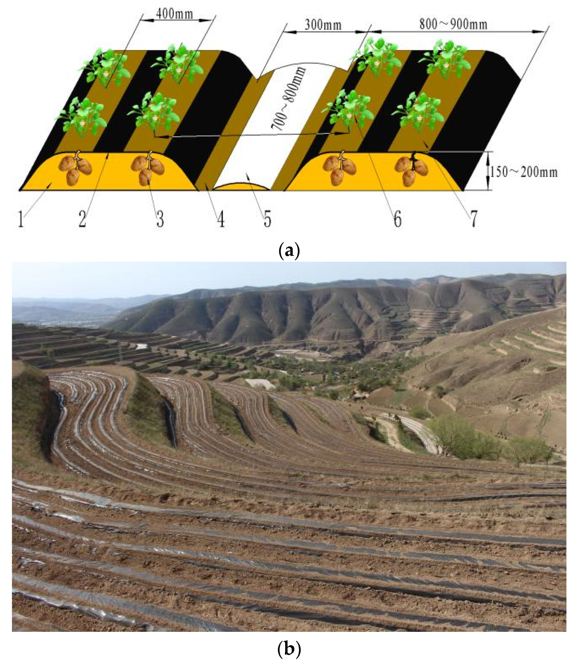
2.1. Planting Agronomy and Farmland Characteristics

Figure 1a is a ridge diagram of one ridge and two rows with a black film covering and a soil covering on top of the film. The width of the ridge bottom is 800~900 mm, the height of the ridge is 150~200 mm, and the width of the blank row in the operation is 300 mm. One ridge is planted in two rows with a row spacing of 400 mm. To store water and retain moisture, a black plastic film with a width of 1200 mm and a thickness of 0.01 mm is used for covering. The top of the film is covered with soil to promote the automatic breaking of the film and reduce the phenomenon of seedling burning [25,26]. According to Figure 1b, most of the arid areas in the northwest are dominated by mountainous terraced fields, with farmland distributed in a stepped shape along the contour lines of the mountain slopes. The farmland is narrow and curved, the soil type is mainly loess in loam. In response to the above situation, a wheeled-chassis potato combine harvester with integrated bagging and ton bag-lifting systems was designed, with a wheeled chassis for more convenient transferring and turning.

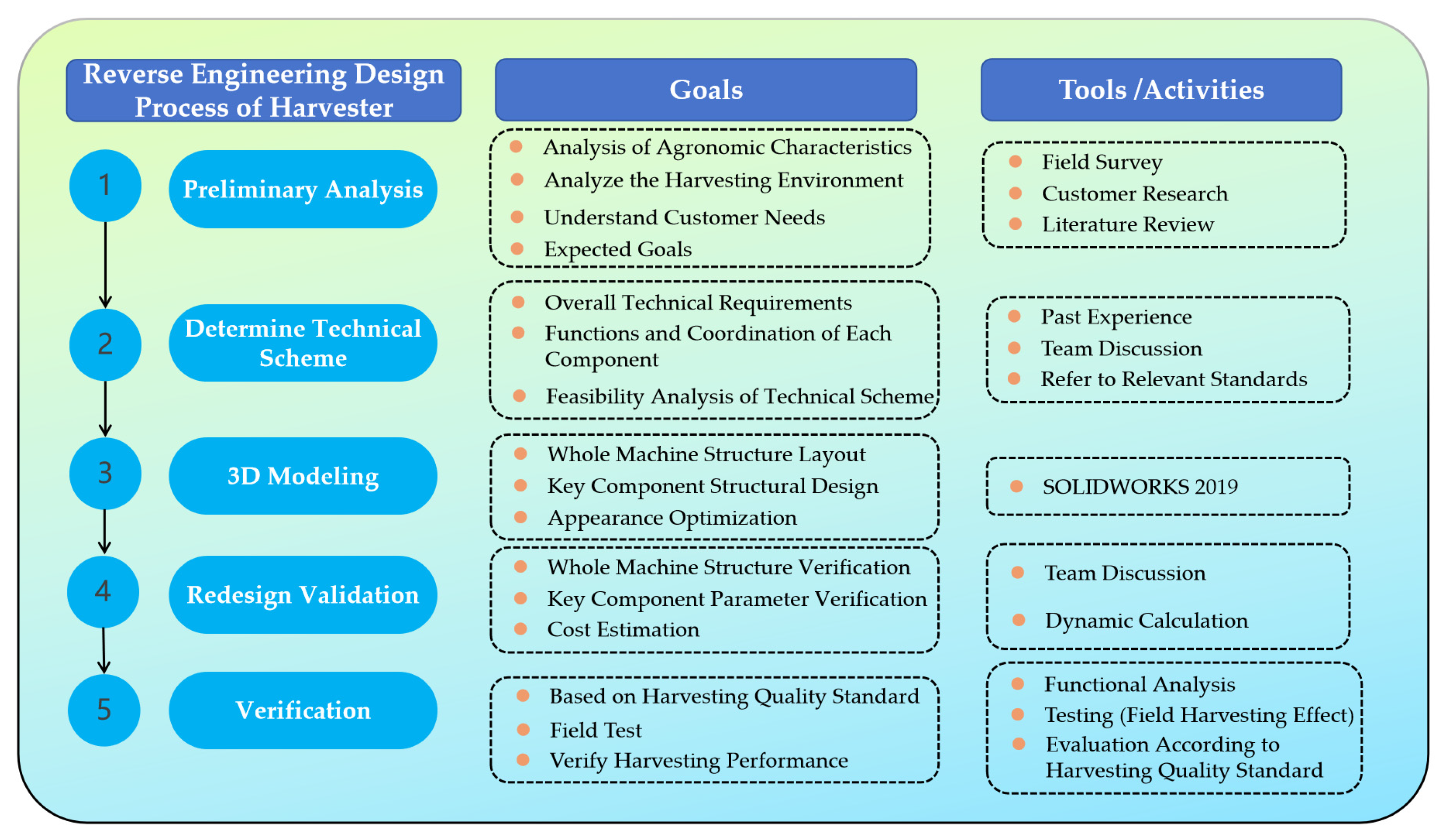
2.2. Research Method

In order to solve the problem of potato combine harvesting in the northwest dry area, a reverse engineering method was adopted. The overall scheme of the method in this article is shown in Figure 2. In more detail, stage 1: preliminary analysis (actual harvesting conditions); stage 2: determine technical scheme; stage 3: 3D modeling (preliminary design); stage 4: redesign (technical scheme verification); and stage 5: verification (field test). This method has also been integrated into tractor safety design by M. Fargnoli, L. Vita, and others [27], which is sufficient proof of the scientific validity of this approach.

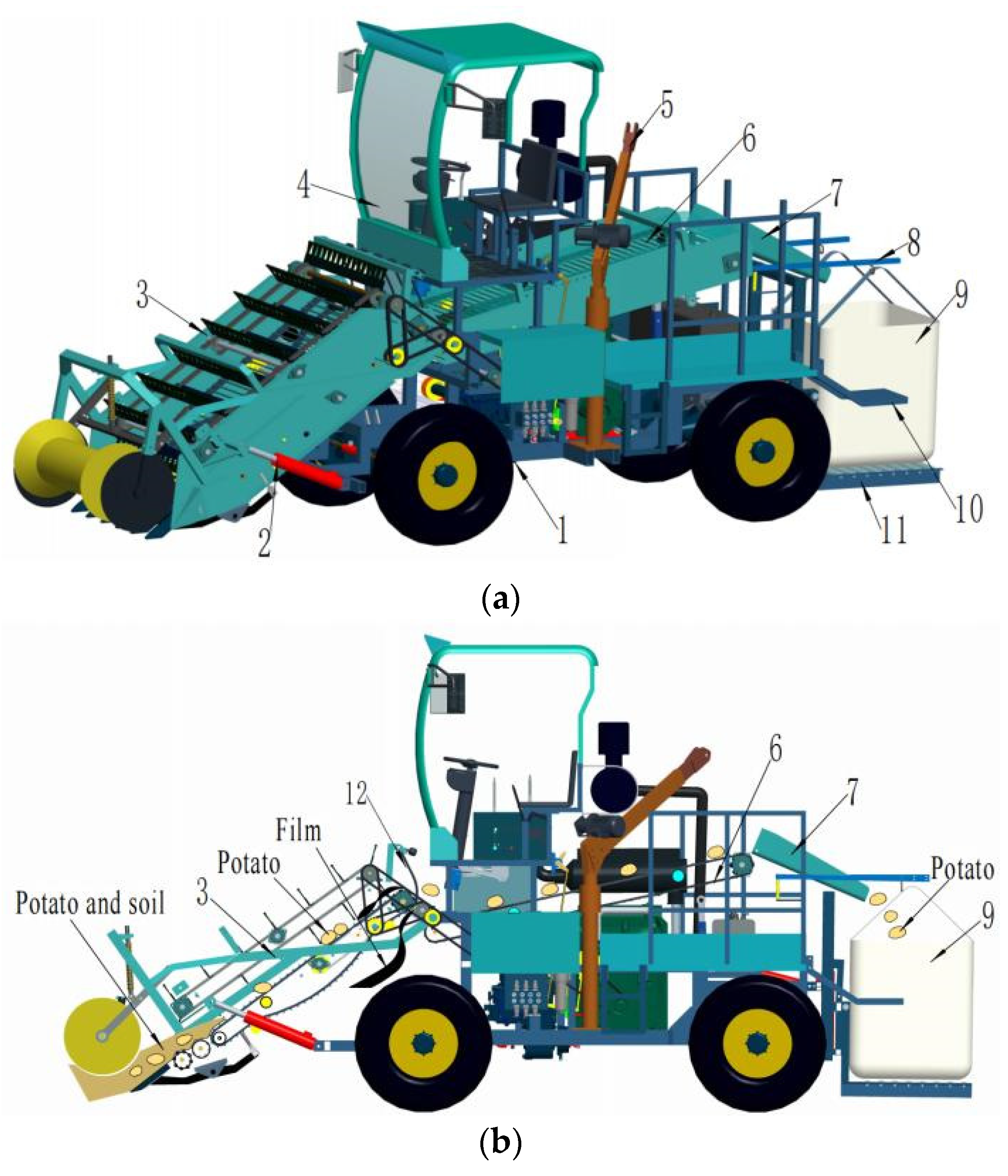
2.3. Overall Structure and Main Parameters

As shown in Figure 3, this machine is composed of a four-wheeled, self-propelled chassis; front harvesting device; lifting hydraulic cylinder; operator’s cabin; electrical lifting device; picking platforms with different paths; a guide groove; ton bag-lifting, rope-tensioning device; foot pedal; ton bag self-unloading platform; a transmission system; etc. The main parameters are shown in Table 1.

2.4. Working Principle

When the machinery entered the field, the front harvesting device was lowered to the working height by controlling the lifting hydraulic cylinder. As the unit moved forward, the mixture of potato, soil, film, and seedlings were excavated and shoveled up and continuously loosened, separated, and transported. Most of the soil, residual seedlings, and residual film were separated out. Potatoes and a small amount of remaining hard soil and debris were thrown to the picking platforms with different paths. There were impurity removal channels on both sides of the picking platforms with different paths. The remaining small amount of soil and debris was sorted and discharged from the machine by the people standing on both sides of the foot pedal. Clean potatoes fell into the rear ton bag through the guide groove. The filled ton bags were lowered and tilted backwards to the ground through the ton bag self-unloading platform. After the field harvest operation was completed, the ton bags in the field were loaded onto other transportation vehicles through the electrical lifting device provided by the machine to complete the transfer. This machine could complete the excavation, separation of potato soil and seedlings, separation of potato film, automatic bagging, and lifting of ton bags in the field in one go.

3. Key Working Units

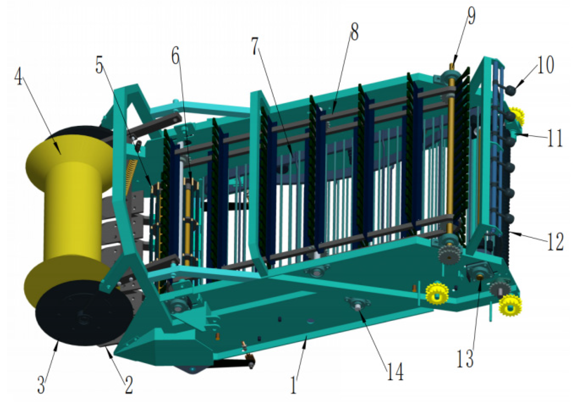
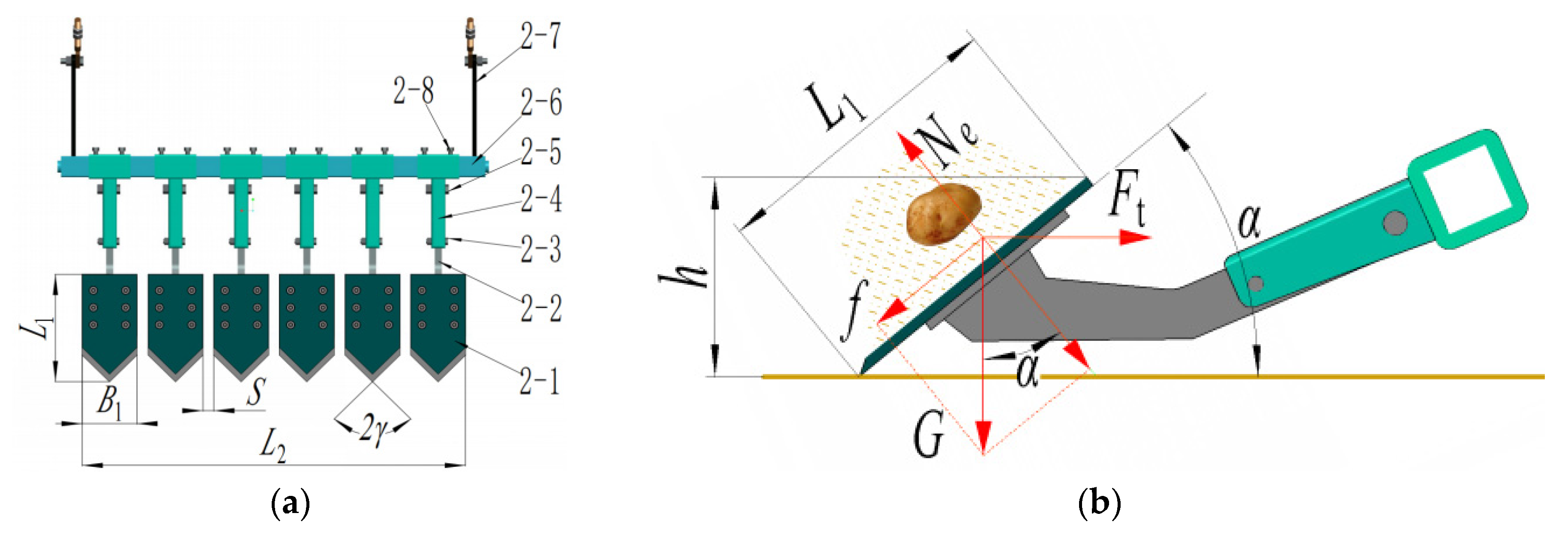
3.1. Front Harvesting Device

3.1.1. The Structure and Working Principle of the Front Harvesting Device

The front lifting device is a crucial component of the potato combine harvester, primarily consisting of the digging device, the composite separation and lifting device, and the film vine clearing device. As shown in Figure 4, it specifically consists of a front harvesting device frame, a depth-limiting, soil-crushing device, two seedling-cutting discs, a split-type digging device, a grid bar soil-crushing roller group, a rod–chain separation screen, a scraper auxiliary lifting device, a counterweight blocking rod, a flexible sorting roller, etc.
During machine operation, the V-shaped depth-limiting roller in the front depth-limiting, soil-crushing device crosses the ridges for operation, combined with an elastic profiling mechanism which not only plays a role in floating, profiling, and stabilizing the excavation depth, but also crushes the hard soil on the membrane, achieving a good soil-crushing effect. Digging the shovel wedge under the ridge, the entire ridge body is lifted up, and the soil, stems, seedlings, and plastic film are continuously separated through the grid bar soil-crushing roller group, rod–chain separation screen, and the film and seedling removal devices. In order to reduce the longitudinal size of the front harvesting device, the inclination angle θ of the rod–chain separation screen is designed to be larger. In order to prevent the potatoes from rolling back and forth and causing scratches, a scraper auxiliary lifting device is installed, which is consistent with the linear speed of the rod–chain separation screen. The potatoes, residual films, and seedlings are transported to the rear film and seedling removal devices. Under the action of the counterweight blocking the rod and flexible impurity removal roller, the residual films and seedlings are discharged from the machine, and the potatoes and remaining soil blocks are transported to the picking platforms by different paths.

3.1.2. The Split-Type Digging Device

The digging device is a key component of the front harvesting device. As a typical soil-touching component, reducing the digging resistance, improving soil-crushing performance, and high reliability are the key design ideas. The digging device of the wheeled-chassis potato combine harvester with integrated bagging and ton bag-lifting systems adopted a split digging device. It had good drag reduction and soil-crushing performance, and an overload protection mechanism was designed. If the shovel tip encounters a hard object during the digging process, the overload protection bolt will be sheared instantaneously to avoid damage to the digging shovel.
Where L1 is the length of the digging shovel, (mm); B1 is the width of the digging shovel, (mm); S is the grass sliding gap, (mm); γ is the digging shovel blade angle, (°); L2 is the width of split-type digging device, (mm); h is the installation height behind the digging shovel, (mm); f is the friction resistance of the digging shovel, (N); G is the soil gravity on the digging shovel, (N); Ne is the reaction force of the digging shovel on the soil, (N); α is the digging shovel insertion angle, (°); and Ft is the force required by the digging shovel to lift the material along the forward direction, (N).
As shown in Figure 5, The split-type digging device consists of a flat digging shovel, a hinged beam frame, an angle adjustment mechanism, a bracket, and an overload protection frame. The designed L2 was 1~1.1 m (adjustable), the B1 was 150 mm, and the S was adjustable from 20~40 mm [28].
In order to ensure the automatic cleaning and sliding cutting function of the digging shovel edge, the angle γ of the digging shovel edge should be satisfied:
90 γ > ϕ
In the formula, φ represents friction angle of soil to steel. It generally takes 30°~36° [15,19,25], and the γ angle of the digging shovel was designed to be 45°, which meets the operational requirements.
The L1 depends on the h and α. The h from the ground behind the digging shovel depends on the installation height of the grid bar soil-crushing roller I and the position of the digging shovel bracket. In the front harvesting device, the designed h behind the excavation shovel from the ground was about 150~192 mm.
The relationship between the L1 and the height h of the rear end of the digging shovel from the ground is shown as follows:
L 1 = h sin α
In addition, the traction resistance of the excavator shovel is greatly affected by soil type, excavation depth, excavation shovel form, and excavation shovel inclination angle, and the following relationship can be established [2,3,29]:
F t cos α f G sin α = 0 N e G cos α F t sin α = 0
In the formula, ε represents the friction coefficient of the soil + potato + seedling mixture on the excavator shovel, ε = tan φ. By calculation, the digging shovel insertion angle is as follows:
α = arctan F t ε G ε F t + G
Field experiments have shown that the length of the digging shovel could easily lead to blockage. In addition, due to the limitation of the h, the α was designed to be 30° to 40° (adjustable). After calculation and analysis, it was determined that L1 was 300 mm.

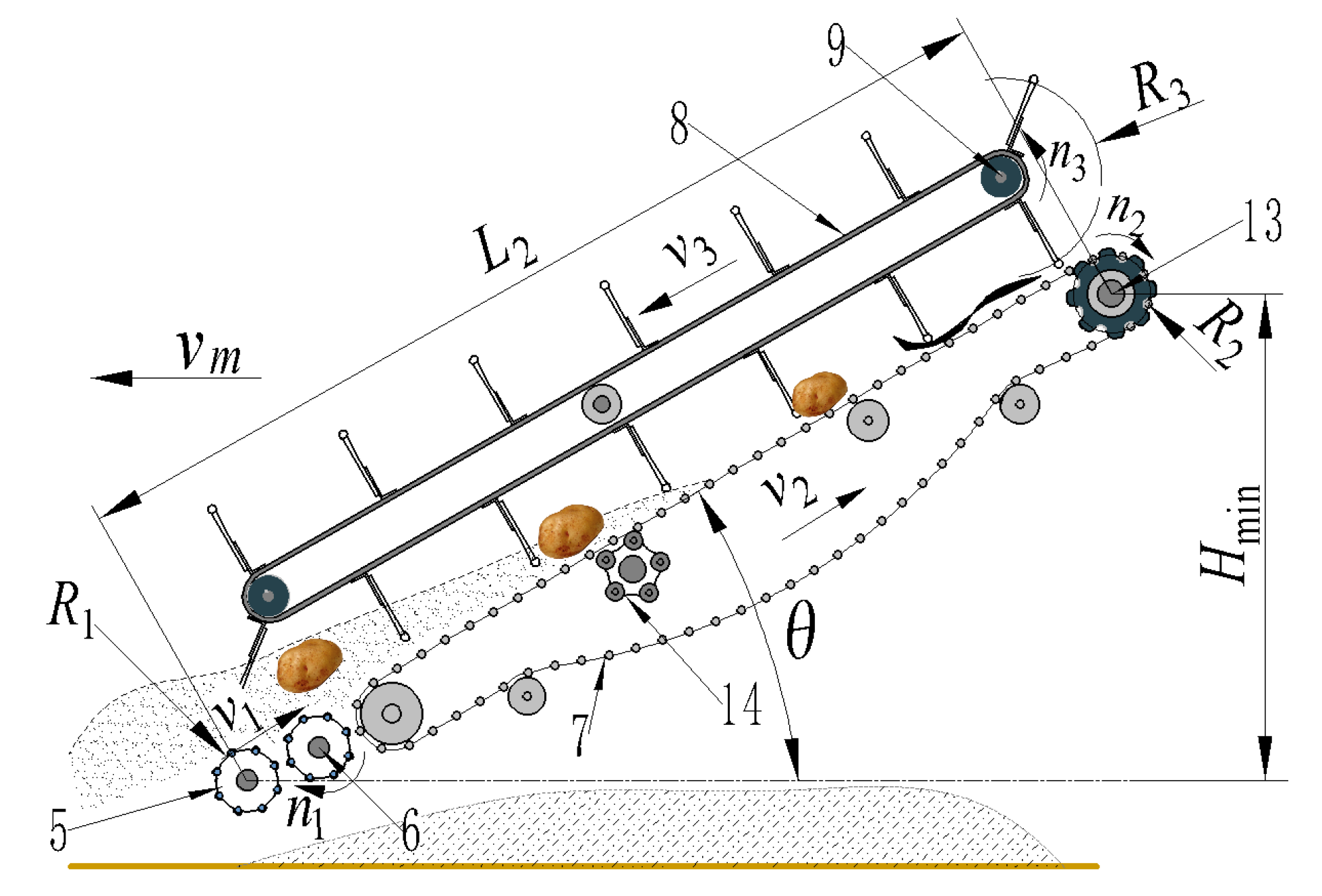
3.1.3. The Composite Separation and Lifting Device

In order to shorten the longitudinal size of the front harvesting device, balance the center of gravity of the entire machine, and improve the separation effect, the front harvesting device adopts the idea of “short path, large inclination angle, first crushing soil, and then separating”, and we designed a composite separation lifting device. As shown in Figure 6, the composite separation and lifting device consists of a grid bar soil-crushing roller group, a rod–chain separation screen, a high-frequency, low-amplitude vibration device, and a scraper auxiliary lifting device.
Where R1 is the radius of the grid crusher roller, mm; n1 is the speed of the grid crusher roller, r/min; v2 is the linear speed of the rod–chain separation screen, m/s; n2 is the driving shaft speed of the rod–chain separation screen, r/min; R2 is dividing radius of the driving wheel of the rod–chain separation screen, mm; n3 is the driving shaft speed of the scraper auxiliary lifting device, r/min; R3 is the scraper rotation radius, mm; v3 is the linear speed of the scraper auxiliary lifting device, m/s; L2 is the effective length of the composite separation lifting device; θ is the inclination angle of the rod–chain separation screen; and Hmin is the minimum installation height at the rear end of the rod–chain separation screen.
If the separation path of the front harvesting device was short and relies solely on the rod–chain separation screen for potato–soil separation, it would not meet the requirements. The split-type digging device lifted the ridge, but the ridge body was not completely crushed, with potatoes still wrapped in a large amount of soil, providing good protection for the potatoes. Therefore, two sets of grid crusher rollers were added in front of the rod–chain separation screen to avoid damaging the potatoes, enhance soil crushing, and accelerate potato–soil separation. The pitch of the grid crusher roller and the rod–chain separation screen were both designed to be 50 mm, with the relationship of the pitch circle radius as follows:
R 1 = R 2 = P Z 2 π
In the formula, P is the pitch of the grid crusher roller and the rod–chain separation screen, taken as P = 0.05 m, and Z is the number of teeth of the rod–chain separation screen driving wheel and the number of grid crusher rollers, taken as Z = 8.
For the sandy loam soil type in the northwest arid region, the v2 should be designed to be about 1.2~1.6 m/s [28]. To avoid the blockage of the potato soil mixture on the screen surface, the line speed of the grid crusher roller and the rod–chain separation screen should be basically the same. Therefore, the n1 and the n2 meet the following relationship:
n 1 = n 2 = 30 v 2 π R 2
In addition, as shown in Figure 6, the relationship between the L2 and the θ is as follows:
L 2 = H min sin θ
The Hmin is limited by the four-wheel, self-propelled chassis and the picking platforms with different paths. Considering the overall layout structure, the Hmin was designed to be 1150 mm, in order to reduce the longitudinal size of the machine as much as possible; the θ was designed to be 42°; the L2 was calculated to be about 1720 mm. According to the literature, the limit inclination angle θmax of the rod–chain separation screen with a pitch of 50 mm was 27.34° [2]. To prevent damage caused by potato chunks rolling off the screen surface, a scraper auxiliary lifting device is installed above the rod–chain separation screen. In order to avoid potato injury, the linear speed of scraper should be consistent with the linear speed of the rod–chain separation screen. The n3 is as follows:
n 3 = 30 v 2 π R 3
In this machine, the rotating diameter of the scraper auxiliary lifting device was designed to be 350 mm; therefore, R3 was taken as 0.175 m. By computing, R1 = R2 = 0.0635 m, n1 = n2 = 180~240 r/min, and n3 = 66~87 r/min.

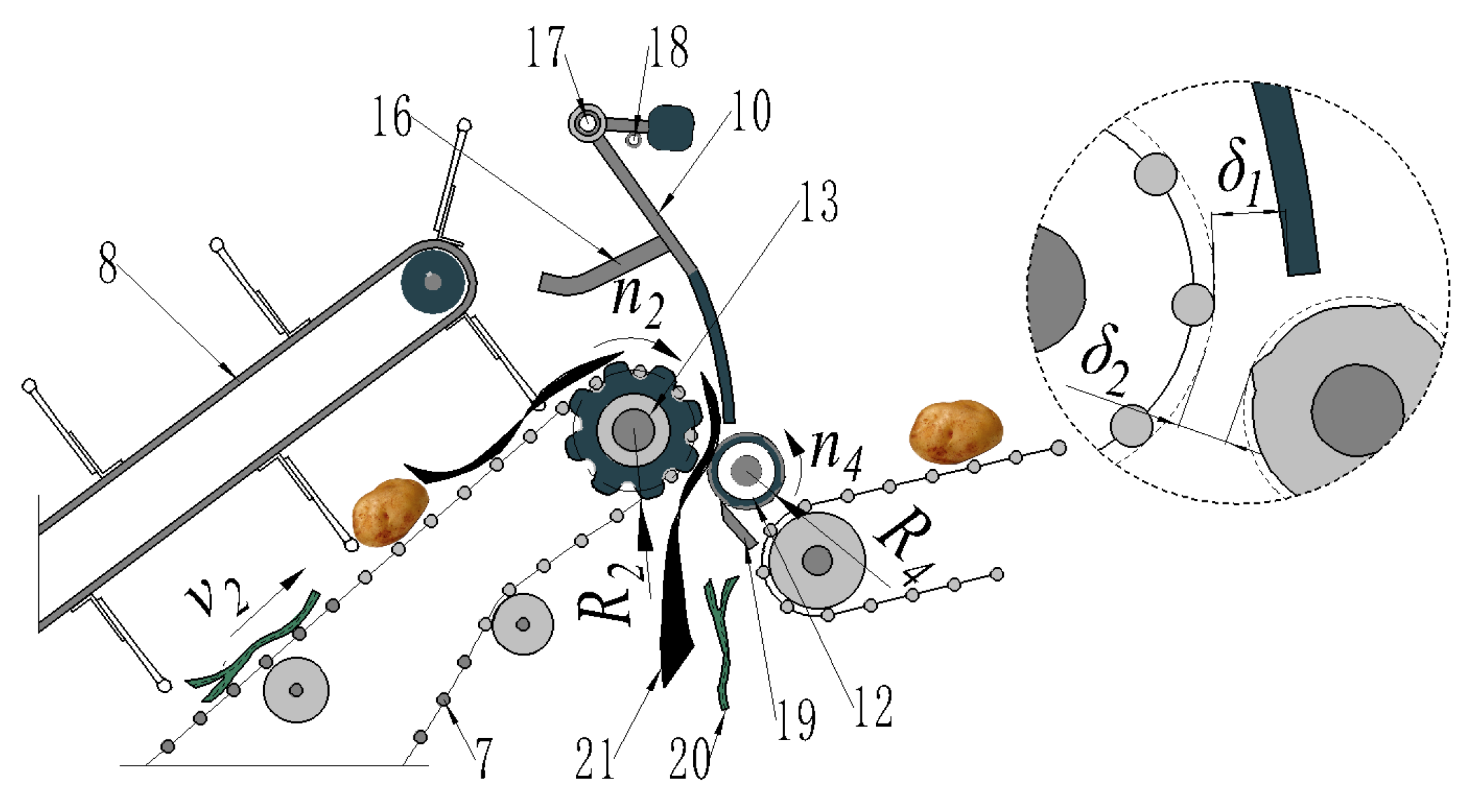
3.1.4. The Film and Vine Clearing Device

In the northwest arid region, potatoes are mainly planted with plastic film to preserve moisture and increase yield. The removal of the residual film and stems is also keyin harvesting [30]. Therefore, it is necessary to design a plastic film and seedling removal device.
Where n4 is the rotational speed of flexible impurity removal roller, r/min; R4 is the radius of the flexible impurity removal roller, mm; δ1 is the gap between the counterweight blocking rod and the rod–chain separation screen, and mm; δ2 is the cleaning gap, mm.
As shown in Figure 7, the film and vine clearing device consists of 6 sets of counterweight blocking rods, a hinged rod, limit rod, comb film teeth, a flexible impurity removal roller, and film-clearing knife. When the machine was in operation, the rod–chain separation screen transported the plastic film and vines to the counterweight blocking rod. Under the counter-rotating movement of the rod–chain separation screen and the flexible impurity removal roller, the plastic film and vines were discharged from the machine through the gap between the rod–chain separation screen and the flexible impurity removal roller. The comb film teeth prevented the plastic film from wrapping around the scraper auxiliary lifting device, and the film-cleaning knife continuously cleaned the plastic film and vines wrapped around the flexible impurity removal roller. The limit rod restricted the position of the counterweight blocking rod. In order to avoid blockage of the plastic film and vines, the speed n4 of the flexible impurity removal roller must meet the following relationship with the speed n2 of the active shaft of the rod–chain separation screen:
n 2 R 2 n 4 R 4
The above has determined that n2 = 180~240 r/min, R2 = 63.5 mm. If the speed of the flexible cleaning roller was too high, it would be easy to scratch potatoes, so the minimum speed of the flexible impurity removal roller n4 was calculated to be 265 r/min. In addition, the δ1 was designed to be 20~35 mm (adjustable), and the δ2 was designed to be 15~30 mm (adjustable).

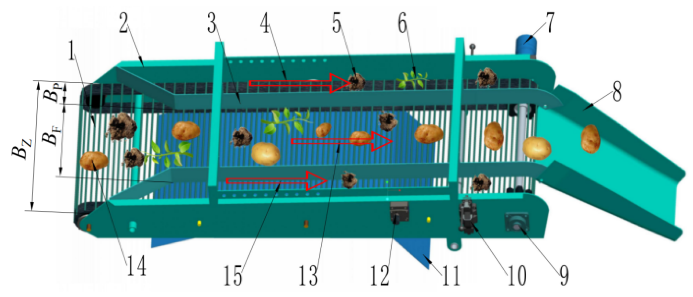
3.2. Picking Platforms with Different Paths

The potatoes, hard soil blocks, vines, and film that are harvested through the front harvesting device need to be mechanically and manually cleared for a second time through the picking platforms with different paths. As shown in Figure 8, the picking platforms with different paths mainly consist of a frame, a baffle plate, a secondary rod–chain separation screen, a guiding groove, a hydraulic transmission system, and a dust shield. When the machine was working, potatoes and residual debris flowed into the sorting channel entrance and continued to be transported backwards by the secondary rod–chain separation screen. The staff standing on both sides of the picking platforms with different paths manually moved the soil blocks and vines in the sorting channel to the impurity removal channel. Clean potatoes continued to flow backwards through the sorting channel into the guide groove and into the ton bag. The secondary rod–chain separation screen was driven by a hydraulic motor for operation. The speed of the secondary rod–chain separation screen could be manually infinitely changed from 0 to 96 r/min through a speed control valve. If necessary, three modes of clockwise rotation, counterclockwise rotation, and shutdown could be selected through a manual switching valve. In addition, an engine was installed below the picking platforms with different paths, and the dust shield provided protection.
Where BZ is the width of the secondary rod–chain separation screen, mm; BF is the width of the middle sorting channel, mm; and BP is the width of the impurity removal channel, mm.
The BZ was designed to be 900 mm, the BP was 200 mm, and the BF was 500 mm. During work, for the convenience of manual sorting and safety, the maximum line speed of the secondary rod–chain separation screen was 0.75 m/s. Therefore, the driving shaft speed of the secondary rod–chain separation screen was
v 6 = n 7 π R 8 30 0.75
Obtained
n 7 = 30 v 6 π R 8
where v6 is line speed of the secondary rod–chain separation screen, m/s; n7 is revolution speed of secondary rod–chain separation screen drive shaft, r/min; and R8 is radius of secondary rod–chain separation screen, taken as 75 mm.
According to the Formulas (10) and (11), when working, the maximum speed n7 was 96 r/min.
As shown in Figure 8, the driving shaft of the two-stage rod–chain separation screen is driven by a hydraulic motor, used a cycloidal hydraulic motor BM1-200 (Like, Jining, China). The displacement of the hydraulic motor is 200 mL/r. The flow rate and power of the motor during operation are as follows:
q m = n 7 V m η v × 10 3
P o m = 2 π n 7 T m 60 × 10 3
where Qm is hydraulic motor flow rate, L/min; Vm is hydraulic motor displacement, 200 mL/r; ηV is volumetric efficiency, take as 0.9; Pom hydraulic motor output power, kW; and Tm is working torque, N·m.
After measurement, the required torque Tm of the secondary rod–chain separation screen was about 60 N·m. The required flow rate qm of the hydraulic motor was calculated to be 21.3 L/min, by Formulas (12) and (13), and the output power Pom was 0.6 kW.

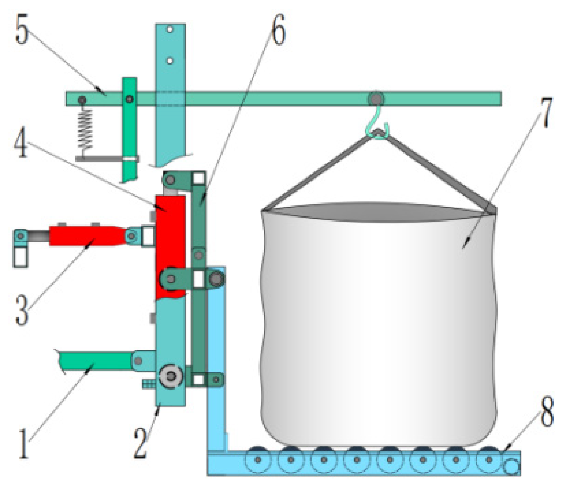
3.3. Ton Bag Self-Unloading Platform

As depicted in Figure 9, the ton bag self-unloading platform encompasses a track gantry, a tilting action hydraulic cylinder, a lifting action hydraulic cylinder, a ton bag-lifting, rope-tensioning device, a small wheel frame, and a roller platform. During the operation of the machine, we suspended the ton bag sling on the hook and tensioned the lifting rope through the action of the tension spring to keep the entrance of the ton bag constantly open, facilitating the entry of potato blocks into the bag. The lifting hydraulic cylinder enables the height of the roller platform to be adjusted at any time, facilitating the unloading of the ton bag. Furthermore, the height of the roller platform can be manually regulated to control the drop height of the potatoes, preventing collision damage among the potato blocks caused by an excessively high drop height. When the ton bag was filled to capacity, the lifting action hydraulic cylinder was slightly elevated, the lifting rope was detached, and subsequently, by manipulating the tilting action hydraulic cylinder, the track door frame, the small wheel frame, and the idler platform were inclined backward, causing the ton bag to automatically drop to the ground. The specific parameters of the ton bag self-unloading platform are presented in Table 2 below.

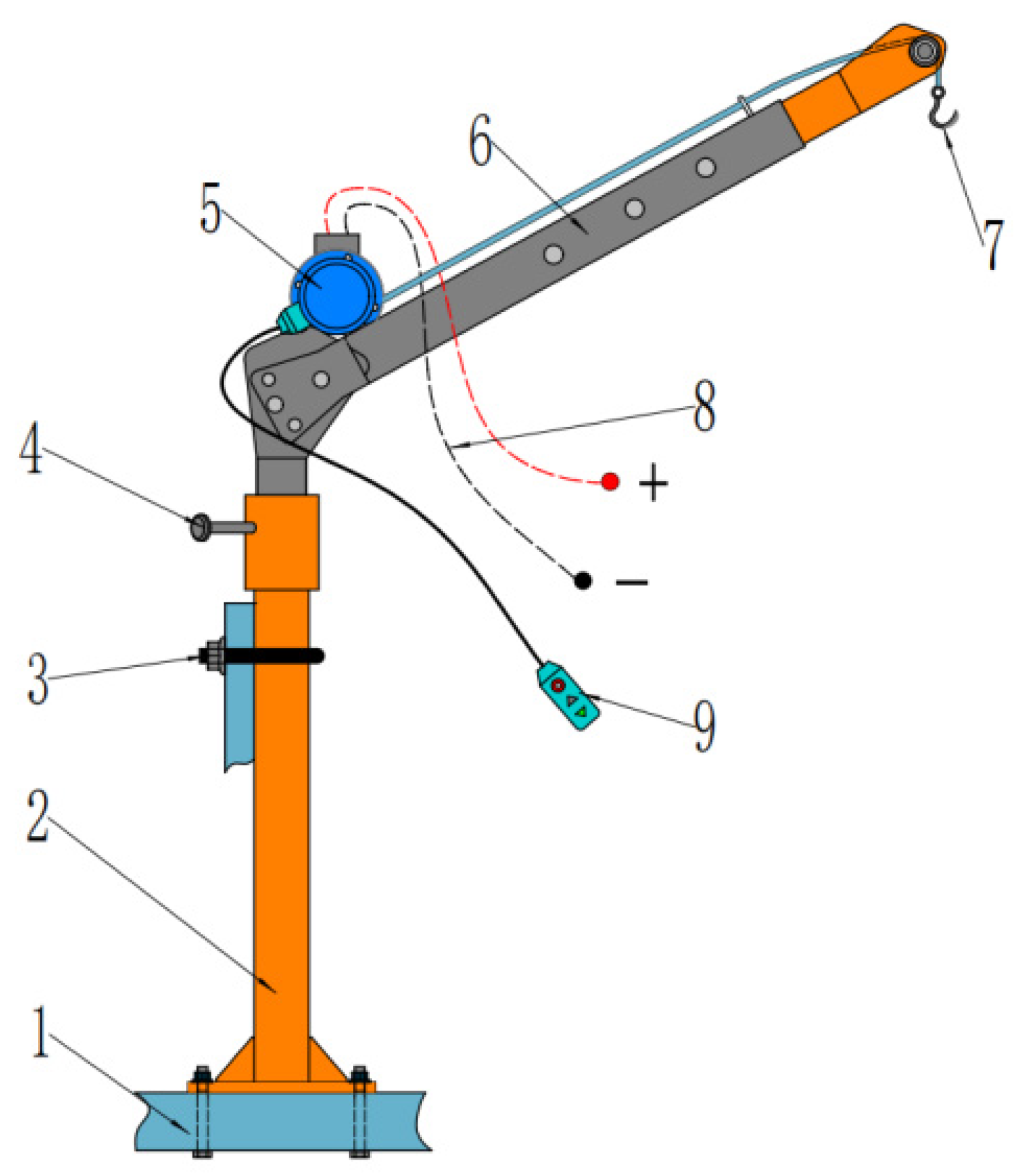
3.4. Electrical Lifting Device

After a piece of farmland is harvested, in general, the ton packaging truck in the field is mostly filled with the help of special lifting equipment, resulting in a high cost and low utilization. Ssecondary entry can easily damage the soil structure. Therefore, an electrical lifting device is installed on the combine harvester to solve the field lifting problem. As shown in Figure 10, the electrical lifting device consists of a column, a set screw, a winch motor, a lifting beam, a steel wire hook, a controller, etc. The column is fixed to the frame by bolts and U-shaped card.
In general, the maximum weight of ton bags filled with potatoes is about 800 kg, the bag-lifting speed is about 6 m/min, and the drum radius Rj is designed to be 0.075 m. Therefore, the relationship between the actual power and speed of the winch motor is as follows [31]:
P S = Q S v d 60 × 1000 η c = M d g v d 60 × 1000 η r
n j = 30 v d 60 π R j
where PS is the actual required power of the winch motor, kW; QS is rated lifting capacity, QS = Md, g = 7840 N; Vd is lifting speed, m/min; Md is a ton of packaging after full total mass, kg; g is acceleration of gravity, g = 9.8 N/kg; hr is mechanical transmission efficiency, taken as ηr = 0.8; and Rj is roller radius, taken as Rj = 0.075 mg.
Through calculation, the actual working power required was determined to be approximately 0.98 kW, and the actual working speed of the roller was approximately 13 r/min. Therefore, a 12 V permanent magnet DC deceleration motor was selected, with a rated power of about 1.4 kW, which meets the technical requirements and has a certain power reserve. The rated speed of the motor was 2400 r/min, and the three-stage planetary gear deceleration system was adopted. The reduction ratio is 185:1.
Estimation of the maximum tensile force of steel wire
S max = Q K m η z η d
where Smax maximum tensile force of steel wire, N; K is roller coefficient of a single roller, taken as K = 1; m is the pulley set multiple, taken as m = 2; ηz and ηd are the efficiency of the pulley group and guide pulley, as well as the efficiency of the sliding bearing, and are both taken as 0.92.
Estimation of minimum diameter of wire rope
d = c S max
where d is wire diameter, mm; c is steel wire selection coefficient, taken as c = 0.104; and Smax is the maximum tension of steel wire, N
By calculation, the maximum tensile force Smax of the steel wire was determined to be approximately 4631 N, and the minimum diameter d of the steel wire was approximately 7.072. Therefore, the diameter d of the steel wire rope was taken as 8 mm. The lifting beam can rotate 360° to adjust the optimal lifting position, and the motor is directly connected to the onboard power supply for use. In addition, the motor comes with an intelligent control module, which has an emergency self-braking function and can automatically stop after detecting a power outage.

4. Results

4.1. Experimental Conditions

In early October 2023, a field harvest experiment was conducted at the potato planting base in Taiping Village, Lujiagou Town, Dingxi City, Gansu Province. The experimental field consisted of two terraced fields with a total area of approximately 0.667 hectares. The planting mode was one ridge, two rows planting with film mulching and soil covering. The planting variety was Longshu 10, and the absolute moisture content of the soil in the field ridge was about 14.3%. The machine harvesting scene and the harvest effect are shown in Figure 11.

4.2. Test Scheme and Method

According to the standards of JB/T 14285-2022 “Potato Harvesting Machinery” and NY/T 648-2015 “Technical Specification for Quality Evaluation of Potato Harvesters”, the working performance of the wheeled-chassis potato combine harvester with integrated bagging and ton bag-lifting systems was tested [32,33]. We mainly measured the potato loss rate, potato damage rate, skin breaking rate, and impurity content during the harvesting process, and we also tested the working conditions of the wheeled, self-propelled chassis; front harvesting device; picking platforms with different paths; automatic loading and unloading platform for ton bags; transmission system; etc.
According to the above standard requirements, the length of the selected testing area shall not be less than 50 m, and the length of the stable areas at both ends shall be set at 10 m. The width of the testing area shall be more than 8 times the working width. During the experiment, multiple round-trips were measured, and three testing areas were randomly selected for each trip. Each testing area was 3 m long, and the width was the working width of the machine. At least 10 repetitions of the experiment were conducted, and the experimental data were measured, and the average value of the repeated experiment measurement results was calculated. According to the above standards, the algorithms for loss rate, damaged potato rate, broken skin rate, and impurity content rate are as follows:
L 1 = Q 1 + Q 2 Q × 100 %
L 2 = Q 3 Q × 100 %
L 3 = Q 4 Q × 100 %
L 4 = Q 5 Q 5 + Q 6 × 100 %
Q = Q 1 + Q 2 + Q 6
where L1 is potato loss rate, (%); L2 is potato damage rate, (%); L3 is skin breaking rate, (%); L4 is impurity content, (%); Q1 is mass of missed potatoes, (kg); Q2 is the mass of missed excavated potatoes, (kg); Q3 is the mass of damaged potatoes, (kg); Q4 is the mass of peeled potatoes, (kg); Q5 is impurity mass, (kg); Q6 is harvested potato mass, (kg); and Q is total potato mass, (kg).

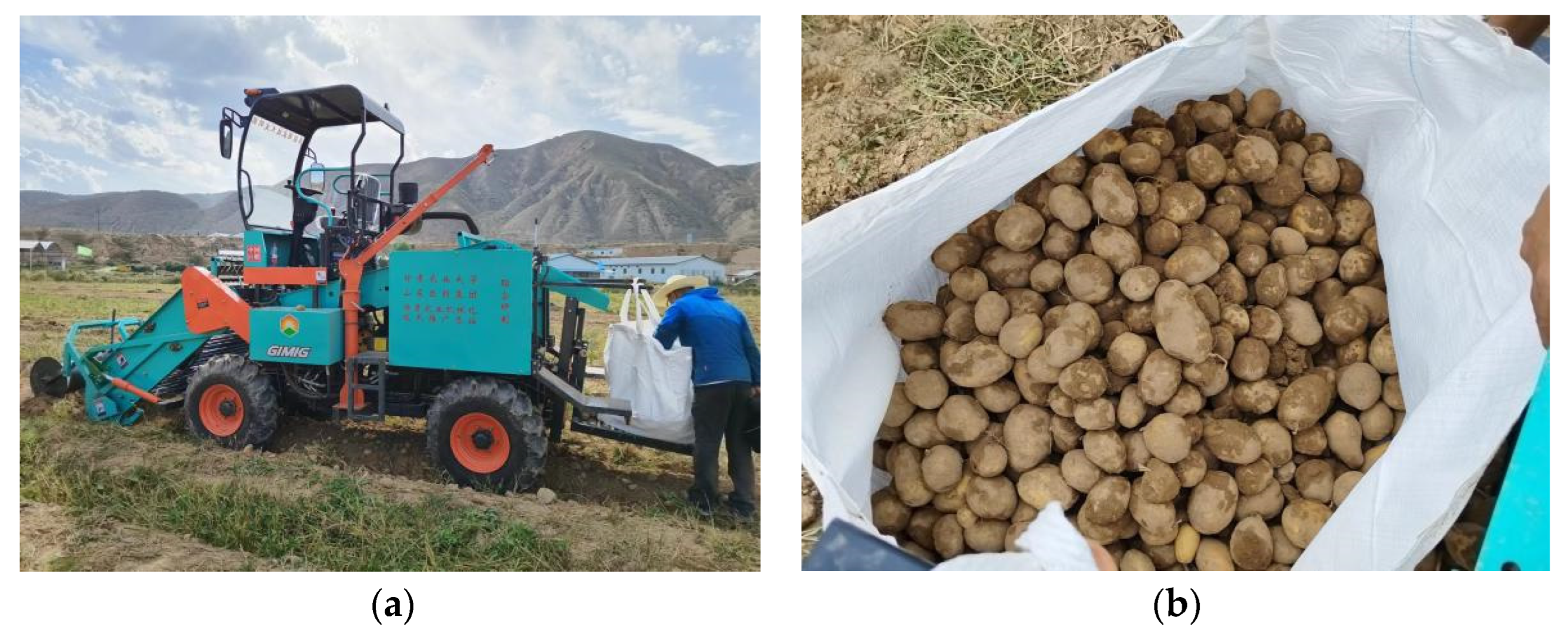
4.3. Analysis of the Field Experiment Results

The field experiment results for the wheeled-chassis potato combine harvester with integrated bagging and ton bag-lifting systems are shown in Table 3.

5. Discussion

According to Table 3, the results showed that the wheeled-chassis potato combine harvester with integrated bagging and ton bag-lifting systems has passed field experiments and determined that the loss rate, potato damage rate, skin breakage rate, and impurity content all meet the national and industry standard requirements. The operation of each component of the equipment was relatively stable, with no other faults except for some mechanism test adjustments. The four-wheel steering system had a small turning radius in the field, which had obvious advantages. The average production rate was about 0.15~0.23 hm2/h. In addition, at present, the potato harvest in northwest arid areas mainly adopts the step-by-step harvesting method, that is, the potato is excavated and laid on the soil surface by simple excavation machinery, and then the final harvest is completed by manual picking and bagging and manual handling to the transport vehicle. Typical harvesting machines such as the 4U-1600 set of pile-type potato diggers (SANNIU, Dingxi, China) were designed by Yang Xiaoping and others [34]. The performance of the two machines was compared and analyzed. The performance indicators are shown in Table 4.
Although the 4U-1600 set of pile-type potato digger has better productivity than the machine studied in this research, the potato combine harvester described in this article can achieve the automatic bagging of potatoes and can also achieve a ton bag-lifting function, with a high level of mechanization. However, the 4U-1600 set of pile-type potato digger adopts a step-by-step harvesting method, which requires a large amount of manual picking and transportation in the later stage, increasing labor costs. Moreover, the picking efficiency in the later stage is relatively low, significantly reducing the overall harvesting efficiency. In addition, the potato damage rate of the harvester designed in this research is significantly lower than that of the 4U-1600 set of pile-type potato digger, confirming that the key components of this study have good damage reduction performance. After a thorough comparison and analysis, this research has enhanced the mechanized harvesting efficiency of potatoes in the arid regions of Northwest China and effectively reduced harvesting costs.

6. Conclusions

Based on the working conditions of potato farming in the arid area of northwest China, a wheeled-chassis potato combine harvester with integrated bagging and ton bag-lifting systems was designed. This machine completes the processes of soil excavation, potato soil separation, potato film separation, the automatic bagging of potatoes, and the lifting of ton bags in the field in one operation. The whole machine has a compact structure, small longitudinal size, low center of gravity, and good climbing performance. We performed this study in order to provide reference for the mechanized harvesting of potato in hilly and mountainous areas of Northwest China.
  • Based on the agronomic requirements and topographical characteristics of potato planting in the northwest arid region, the overall design scheme of the whole machine is determined. The key components are designed and analyzed by SOLID2019 3D software and a dynamic analysis model. The structure and working parameters of the split-type digging device, composite separation and lifting device, the film and vine clearing device, the picking platforms with different paths, the ton bag self-unloading platform, and the electrical lifting device were determined, which improved the potato harvesting quality and the reliability and adaptability of the key components.
  • Field experiments have shown that the loss rate of the wheeled-chassis potato combine harvester with integrated bagging and ton bag-lifting systems is 2.1%, the potato damage rate is 1.7%, the skin breaking rate is 2.5%, the impurity content is 1.9%, and the productivity is about 0.15~0.23 hm2/h. The field performance test indicators all meet the national and industry standards requirements. The potato harvesting machine described in this article has a high degree of mechanization and good harvesting performance, which effectively improves work efficiency and saves a lot of labor costs, playing a good role in promoting the development of the potato industry in the arid areas of Northwest China.

Author Contributions

Methodology, H.W., W.Z. and W.S.; investigation, H.W., W.Z., W.S. and X.L.; software, H.W., R.S., X.L. and H.Z.; formal analysis, H.W., W.Z. and K.G.; resources, W.Z. and W.S.; writing—original draft, H.W.; writing—review and editing, H.W., R.S. and P.C.; funding acquisition, W.Z., W.S. and H.W. All authors have read and agreed to the published version of the manuscript.

Funding

This work was supported by the National Key R&D Program (2023YFD200090502); Gansu Province Major Special Project (22ZD6NA046); Gansu Provincial Department of Education: Major Cultivation Project of University Research and Innovation Platform (2024CXPT-15); Gansu Province Modern Silk Road Cold and Drought Agriculture Science and Technology Support Project (GSLK-2021-14); and the 2022 Gansu Province Excellent Graduate Student “Innovation Star” Project (2022CXZX-640).

Institutional Review Board Statement

Not applicable.

Data Availability Statement

The data are reported within the article.

Conflicts of Interest

Authors Pengfei Chen and Kuizeng Gao were employed by the Technology R&D Center, Shandong Juming Machinery Co., Ltd. All authors declare that the research was conducted in the absence of any commercial or financial relationships that could be construed as a potential conflict of interest..

References

  1. Wang, Y.; Shi, M.; Zhang, R.; Zhang, W.; Liu, Y.; Sun, D.; Wang, X.; Qin, S.; Kang, Y. Legume-potato rotation affects soil physicochemical properties, enzyme activity, and rhizosphere metabolism in continuous potato cropping. Chem. Biol. Technol. Agric. 2023, 10, 132. [Google Scholar] [CrossRef]
  2. Jia, B.; Sun, W.; Zhao, Z.; Wang, H.; Zhang, H.; Liu, X.; Li, H. Design and field test of a remotely controlled self-propelled potato harvester with manual sorting platform. Am. J. Potato Res. 2023, 100, 193–209. [Google Scholar] [CrossRef]
  3. Ju, Y.; Sun, W.; Zhao, Z.; Wang, H.; Liu, H.; Zhang, H.; Li, H. Development and testing of a self-propelled machine for combined potato harvesting and residual plastic film retrieval. Machines 2023, 11, 432. [Google Scholar] [CrossRef]
  4. Wei, Z.; Li, H.; Mao, Y.; Sun, C.; Li, X.; Liu, W.; Su, G. Experiment and analysis of potato-soil separation based on impact recording technology. Int. J. Agric. Biol. Eng. 2019, 12, 71–80. [Google Scholar] [CrossRef]
  5. Li, X.; Wei, Z.; Su, G.; Wang, X.; Zhang, X.; Wang, X.; Cheng, X.; Jin, C. Parameter optimization and experiment of air-screen potato-stone cleaning device based on gas-solid coupling. Trans. Chin. Soc. Agric. Mach. 2024, 55, 96–108. [Google Scholar]
  6. Wang, X.; Wei, Z.; Su, G.; Meng, P.; Wang, F.; Zhang, X.; Wang, X.; Cheng, X.; Li, Z.; Jin, C. Design and experiment of simple harmonic disturbance separation device for potato harvester. Trans. Chin. Soc. Agric. Mach. 2024, 101–112. [Google Scholar]
  7. Wei, Z.; Wang, Y.; Li, X.; Wang, J.; Su, G.; Meng, P.; Han, M.; Jin, C.; Li, Z. Design and experiments of the potato combine harvester with elastic rubbing technology. Trans. Chin. Soc. Agric. Eng. 2023, 39, 60–69. [Google Scholar]
  8. Wei, Z.; Wang, X.; Li, X.; Wang, F.; Li, Z.; Jin, C. Design and experiment of crawler self-propelled sorting type potato harvester. Trans. Chin. Soc. Agric. Mach. 2023, 54, 95–106. [Google Scholar]
  9. Wang, H.; Zhao, W.; Sun, W.; Zhang, H.; Liu, X.; Li, H. Research progress on the technology and equipment for potato mechanized harvesting. Trans. Chin. Soc. Agric. Eng. 2023, 39, 1–22. [Google Scholar]
  10. Wei, Z.; Wang, Y.; Su, G.; Zhang, X.; Wang, X.; Cheng, X.; Li, X.; Jin, C. Research progress in the technology and equipment for potato mechanized harvesting and impurity removal. Trans. Chin. Soc. Agric. Eng. 2024, 40, 1–13. [Google Scholar]
  11. Li, T.; Yang, M.; Zhang, X.; Zhang, E.; Cheng, X.; Wang, X. Potato production technology and difference of mechanization level in northwest China. Trans. Chin. Soc. Agric. Mach. 2020, 51, 307–313. [Google Scholar]
  12. Wei, H.; Wang, D.; Lian, W.; Shao, S.; Yang, X.; Huang, X. Development of 4UFD-1400 type potato combine harvester. Trans. Chin. Soc. Agric. Eng. 2013, 29, 11–17. [Google Scholar]
  13. Wei, H.; Zhang, J.; Yang, X.; Huang, X.; Dai, L.; Sun, G.; Liu, X. Improved design and test of 4UFD-1400 type potato combine harvester. Trans. Chin. Soc. Agric. Eng. 2014, 30, 12–17. [Google Scholar]
  14. Zhang, Z.; Li, Y.; Wang, H.; Zhang, Z.; Liu, X. Research progress on key technology and equipment of potato mechanized harvest. J. Yunnan Agric. Univ. 2021, 36, 1092–1103. [Google Scholar]
  15. Yang, D.; Wang, X.; Liu, M.; Li, Y.; Chen, X.; Chen, Z. Design and experiment of self-propelled potato collecting and bagging machine. Trans. Chin. Soc. Agric. Mach. 2024, 55, 85–95. [Google Scholar]
  16. Wang, X.; Lyu, D.; Ren, J.; Zhang, M.; Meng, P.; Li, X. Design and parameter optimization of the cleaning device for a bagged potato combine harvester. Trans. Chin. Soc. Agric. Eng. 2022, 38, 8–17. [Google Scholar]
  17. Lyu, J.; Tian, Z.; Wu, J.; Yang, Y.; Shang, Q.; Wang, Y.; Liu, Z. Design and experiment on 4U1Z vibrating potato digger. Trans. Chin. Soc. Agric. Eng. 2015, 31, 39–47. [Google Scholar]
  18. Lyu, J.; Tian, Z.; Yang, Y.; Shang, Q.; Wu, J. Design and experimental analysis of 4U2A type double-row potato digger. Trans. Chin. Soc. Agric. Eng. 2015, 31, 17–24. [Google Scholar]
  19. Zhang, Z.; Wang, H.; Li, Y.; Yang, X.; Issa, I.; Zhang, Z. Design and experiment of multi-stage separation buffer potato harvester. Trans. Chin. Soc. Agric. Mach. 2021, 52, 96–109. [Google Scholar]
  20. Wei, Z.; Li, H.; Su, G.; Sun, C.; Liu, W.; Li, X. Development of potato harvester with buffer type potato-impurity separation sieve. Trans. Chin. Soc. Agric. Eng. 2019, 35, 1–11. [Google Scholar]
  21. Wei, Z.; Su, G.; Li, X.; Wang, F.; Sun, C.; Meng, P. Parameter optimization and test of potato harvester wavy sieve based on EDEM. Trans. Chin. Soc. Agric. Mach. 2020, 51, 109–122. [Google Scholar]
  22. Yang, R.; Yang, H.; Shang, S.; Ni, Z.; Liu, Z.; Guo, D. Design and experiment of vertical circular separating and conveying device for potato combine harvester. Trans. Chin. Soc. Agric. Eng. 2018, 34, 10–18. [Google Scholar]
  23. Yang, R.; Tian, G.; Shang, S.; Wang, B. Zhang, J.; Zhan, Y. Design and experiment of roller group type potato soil separator for potato harvester. Trans. Chin. Soc. Agric. Mach. 2023, 54, 107–118. [Google Scholar]
  24. Wang, F.; Cao, Q.; Li, Y.; Pang, Y.; Xie, K.; Zhang, Z. Design and trafficability experiment of self-propelled potato harvester in hilly and mountainous areas. Trans. Chin. Soc. Agric. Mach. 2023, 54, 10–19. [Google Scholar]
  25. Sun, W.; Wang, H.; Zhao, W.; Zhang, H.; Liu, X.; Wu, J. Design and experiment of potato digger with waste film recollection for complete film mulching, soil covering and ridge sowing pattern. Trans. Chin. Soc. Agric. Mach. 2018, 49, 105–114. [Google Scholar]
  26. Sun, W.; Liu, X.; Wang, H.; Zhang, H.; Wu, J.; Yang, X.; Wang, G. Design and test of double crank multi-rod hill-drop potato planter on plastic film. Trans. Chin. Soc. Agric. Eng. 2018, 34, 34–42. [Google Scholar]
  27. Fargnoli, M.; Vita, L.; Gattamelata, D.; Laurendi, V.; Tronci, M. A reverse engineering approach to enhance machinery design for safety. In Proceedings of the DESIGN 2012, the 12th International Design Conference, Dubrovnik, Croatia, 21–24 May 2012. [Google Scholar]
  28. Zhang, X. Agricultural Machinery Design Manual, 1st ed.; China Agricultural Science and Technology Press: Beijing, China, 2007; pp. 1053–1086. [Google Scholar]
  29. Chen, X.; Hu, Z.; Wang, B.; You, Z.; Peng, B.; Hu, L. Design and parameter optimization of sweet-potato-stalk separator for single row sweet potato combine harvester. Trans. Chin. Soc. Agric. Eng. 2019, 35, 12–21. [Google Scholar]
  30. Zhang, X.; Liu, J.; Shi, Z.; Jin, W.; Yan, J.; Yu, M. Design and parameter optimization of reverse membrane and soil separation device for residual film recovery machine. Trans. Chin. Soc. Agric. Eng. 2019, 35, 46–55. [Google Scholar]
  31. Cui, R.L.; Zhao, L.M. Design of Lifting Mechanism for MG650 Beam Lifting Machine. In Proceedings of the 9th National Local Mechanical Engineering Society Academic Annual Conference, Zhengzhou, China, 1–3 November 2019. [Google Scholar]
  32. NY/T 648-2015; Technical Specifications for Quality Evaluation of Potato Harvesters. Standards of China: Beijing, China, 2015.
  33. JB/T 14285-2022; Potato Harvesting Machinery. Standards of China: Beijing, China, 2022.
  34. Yang, X.; Wei, H.; Zhao, W.; Jiang, Y.; Dai, L.; Huang, X. Design and experiment of 4U-1600 set of pile type potato digger. Trans. Chin. Soc. Agric. Mach. 2020, 51, 83–92. [Google Scholar]
Figure 1. Overview of potato planting in Northwest China: (a) planting patterns in northwest arid areas; (b) terraced field landscape in northwest hilly and mountainous areas. 1. Ridge body; 2. black agricultural film; 3. potato; 4. agricultural film boundary; 5. blank row; 6. potato seedlings; and 7. cover the soil on top of the plastic film.
Agriculture 14 01461 g001
Figure 2. General framework of the research method.
Agriculture 14 01461 g002
Figure 3. Overall structure and schematic diagram: (a) axonometric drawing of complete machine structure; (b) schematic diagram of the working principle of the whole machine. 1. Wheeled, self-propelled chassis; 2. lifting hydraulic cylinder; 3. front harvesting device; 4. operator’s cabin; 5. electrical lifting device; 6. picking platforms with different paths; 7. guide groove; 8. ton bag-lifting, rope-tensioning device; 9. ton bag; 10. foot pedal; 11. ton bag self-unloading platform; and 12. potato film separation device.
Agriculture 14 01461 g003
Figure 4. Structural diagram of front harvesting device. 1. Front harvesting device frame; 2. split-type digging device; 3. seedling-cutting disc; 4. depth-limiting, soil-crushing device; 5. grid bar soil-crushing roller I; 6. grid bar soil-crushing roller II; 7. rod–chain separation screen; 8. scraper auxiliary lifting device; 9. scraper auxiliary lifting device drive shaft; 10. counterweight blocking rod; 11. front harvesting device hinge shaft; 12. flexible impurity removal roller; 13. rod–chain separation screen driving shaft; and 14. high-frequency, low-amplitude vibration device.
Agriculture 14 01461 g004
Figure 5. Split-type digging device: (a) Structure of split-type digging device. (b) Force analysis of digging shovel. 2-1. Flat digging shovel; 2-2. bracket; 2-3. overload shear bolt; 2-4. overload protection frame; 2-5. hinge bolts; 2-6. hinged beam frame; 2-7. angle adjustment mechanism; and 2-8. limit bolt.
Agriculture 14 01461 g005
Figure 6. Composite separation and lifting device. 5. Grid crusher roller I; 6. grid crusher roller II; 7. rod–chain separation screen; 8. scraper auxiliary lifting device; 9. scraper auxiliary lifting device drive shaft; 13. rod–chain separation screen driving shaft; and 14. high-frequency amplitude vibration device.
Agriculture 14 01461 g006
Figure 7. Principle of film and vine clearing device. 7. Rod–chain separation screen; 8. scraper auxiliary lifting device; 10. counterweight blocking rod; 12. flexible impurity removal roller; 13. rod–chain separation screen driving shaft; 16. comb film teeth; 17. hinged rod; 18. limit rod; 19. film-clearing knife; 20. separated stem and vine; and 21. separated plastic film.
Agriculture 14 01461 g007
Figure 8. Structure diagram of picking platforms with different paths. 1. Secondary rod–chain separation screen; 2. frame; 3. baffle plate; 4. impurity removal channel; 5. soil block; 6. seedling vine; 7. hydraulic motor; 8. guiding groove; 9. secondary rod–chain separation screen drive shaft; 10. manual directional valve; 11. dust shield; 12. speed-regulating valve; 13. sorting channel; 14. potato; and 15. impurity removal channel.
Agriculture 14 01461 g008
Figure 9. Structure diagram of the ton bag self-unloading platform. 1. Frame; 2. track gantry; 3. tilting action hydraulic cylinder; 4. lifting action hydraulic cylinder; 5. ton bag lifting rope tensioning device; 6. small wheel frame; 7. ton bag; and 8. roller platform.
Agriculture 14 01461 g009
Figure 10. Structural diagram of electrical lifting device. 1. Frame; 2. column; 3. U-shaped card; 4. set screw; 5. winch motor; 6. lifting beam; 7. steel wire hook; 8. power cord; and 9. controller.
Agriculture 14 01461 g010
Figure 11. Field experiment: (a) machine harvesting scene; (b) bagged potatoes.
Agriculture 14 01461 g011
Table 1. Main technical parameters of the homework machine.
IndexData
Structural styleWheeled self-propelled type
Engine power (kW)73.5
Engine rated speed (R·min−1)2600
Wheel track (m)1.38
Wheelbase/m2.2
Minimum turning radius (m)2.8
Overall machine dimensions:
(length × width × height) (m × m × m)
5.6 × 1.78 × 2.8
Working width (m)1.1
Number of rows harvested2
Digging depth (m)0~240
Potato harvest methodTon bag
Productivity (hm2·h−1)0.15~0.23
Table 2. Parameters of the ton bag self-unloading platform.
IndexParameter
Adapt to the size of ton bag (length × width × height)/(m × m × m)0.8 × 0.8 × 1
Rope formDouble-ring
Roller platform minimum ground clearance (mm)200
Roller platform maximum ground clearance (mm)520
Lifting action hydraulic cylinder travel (mm)320
Tilting action hydraulic cylinder travel (mm)100
Roller platform maximum tilt angle (°)15
Hydraulic cylinder control modeElectrical control
Table 3. Results of field experiments.
Determination StandardTechnical StandardTests the Result
Potato loss rate (%)≤32.1
Potato damage rate (%)≤21.7
Skin breaking rate (%)≤32.5
Impurity content (%)≤41.9
Table 4. Working performance of two potato harvesters.
Performance IndexPotato Harvesting Machine
This Harvester4U-1600 Set of Pile-Type Potato Digger
Productivity (hm2·h−1)0.15~0.230.35~0.55
Potato damage rate (%)1.73.36
Skin breaking rate (%)2.5/
Potato obvious rate (%)Automatic bagging95.11
Impurity content (%)1.9/
Disclaimer/Publisher’s Note: The statements, opinions and data contained in all publications are solely those of the individual author(s) and contributor(s) and not of MDPI and/or the editor(s). MDPI and/or the editor(s) disclaim responsibility for any injury to people or property resulting from any ideas, methods, instructions or products referred to in the content.

