Article

Research on a Novel Citrus Reticulata ‘Chachi’ Orientation Adjustment Mechanism (COAM) and Machine Vision Guidance Control

College of Engineering, South China Agricultural University, Guangzhou 510642, China
*
Author to whom correspondence should be addressed.
Agriculture 2024, 14(9), 1516; https://doi.org/10.3390/agriculture14091516 (registering DOI)
Submission received: 13 August 2024 / Revised: 28 August 2024 / Accepted: 1 September 2024 / Published: 3 September 2024
(This article belongs to the Section Agricultural Technology)

Abstract

:
The initial processing of Citrus Reticulata ‘Chachi’ involves peeling as a crucial step. Currently, there is some semi-automatic peeling equipment available. However, due to the requirement of adjusting the orientation of Citrus Reticulata ‘Chachi’ to ensure the stem (or navel) is facing upwards before peeling and because the peeling process must retain the stem as a marker for fresh fruit picking, the loading of Citrus Reticulata ‘Chachi’ for peeling still solely relies on manual operation, resulting in low efficiency and poor standardization. With the rapid growth of the pericarp of the Citrus Reticulata ‘Chachi’ industry, semi-automatic processing equipment is no longer able to meet production demands. The loading issue before peeling Citrus Reticulata ‘Chachi’ is a complex hand–eye coordination problem. In response to this issue, this paper proposes a novel Citrus Reticulata ‘Chachi’ orientation adjustment mechanism (COAM). This mechanism utilizes frictional force to adjust the orientation of Citrus Reticulata ‘Chachi’. First, the conceptual design and kinematic modelling analysis of the mechanism were conducted. Next, the omnidirectional friction-driven wheels were optimized in design. Subsequently, a prototype was manufactured and assembled to conduct validation tests on its open-loop motion performance. Finally, a visual feedback-guided algorithm was introduced to complement the kinematic model, enabling the automatic and rapid adjustment of Citrus Reticulata ‘Chachi’ orientation. The experimental results indicate that the COAM designed in this study can effectively and rapidly adjust the orientation of Citrus Reticulata ‘Chachi’ fruits of different sizes and shapes. It demonstrates strong adaptability, and under visual feedback guidance, the orientation adjustment error is less than 10% of the fruit’s diameter. This meets the requirements for automated production in the initial processing of Citrus Reticulata ‘Chachi’. The research presented in this paper also provides new insights for the orientation adjustment and loading of similar spherical fruits.

1. Introduction

Citrus Reticulata ‘Chachi’ belongs to the Rutaceae family and Citrus genus. It is a small deciduous tree cultivated in regions such as South China, Tibet, and Taiwan Province [1,2]. Currently, the main production area of Citrus Reticulata ‘Chachi’ is Xinhui District, Guangdong Province, and it has become a characteristic agricultural product of Jiangmen City, known locally as Xinhui Citrus [3]; its primary processed product is the “pericarp of the Citrus Reticulata ‘Chachi’” [4]. As shown in Figure 1, the pericarp of the Citrus Reticulata ‘Chachi’ is often divided into three segments, with a thickness of approximately 1~4 mm, and its outer surface features abundant sunken oil glands [5]. From the perspective of traditional Chinese medicine, the pericarp of the Citrus Reticulata ‘Chachi’ has the functions of drying dampness, resolving phlegm, regulating qi, and invigorating the spleen [6]. It provides excellent health benefits in cardiovascular, respiratory, endocrine, gastrointestinal systems [7,8], as well as in beauty and skin care, possessing the characteristics of both food and medicine [9,10]. From the perspective of Western medicine, the flavonoids contained in the pericarp of the Citrus Reticulata ‘Chachi’ not only have anti-inflammatory and free radical scavenging effects [11,12] but can also inhibit cancer cell growth to some extent [13]. Additionally, the alkaloids and inositol contained in it are also beneficial substances for the human body [14]. These characteristics determine its high medicinal and economic value, leading to annual increases in the production and output value of Citrus Reticulata ‘Chachi’ [15].
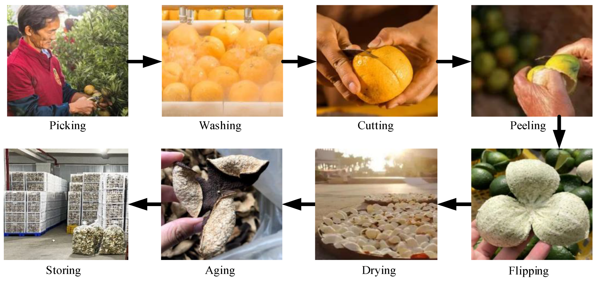
The traditional process of making the pericarp of the Citrus Reticulata ‘Chachi’ involves multiple steps, as shown in Figure 2. Generally, it includes picking, washing, cutting, peeling, flipping, sun-drying, aging, and storing [16,17,18]. Among these, peeling is a crucial step in the initial processing of Citrus Reticulata ‘Chachi’. The traditional peeling methods for Citrus Reticulata ‘Chachi’ can be divided into the “three cuts on the front” and “two cuts on the back” methods. The back-cutting method is used when the stem of the Citrus Reticulata ‘Chachi’ is facing upward, while the front-cutting method is used when the stem is facing downward. Both methods result in the peel being divided into a tripetalous form [5]. As seen in Figure 3, regardless of the peeling method used, it is essential to preserve the intact stem to distinguish between freshly picked and fallen fruits. Both the front-cutting and back-cutting methods divide the orange peel into a tripetalous form, with a larger curled surface area, facilitating the preservation of peel integrity during the flipping and sun-drying processes [19].
With the rapid growth of the pericarp of the Citrus Reticulata ‘Chachi’ industry in recent years, it has gradually diversified [20]. Various deep-processed products of the pericarp of the Citrus Reticulata ‘Chachi’ continue to be introduced [21], achieving certain results in the research of medicinal and edible products. Market demand has surged, posing higher requirements for the automation of Citrus Reticulata ‘Chachi’ pericarp processing [22,23]. Currently, available semi-automatic equipment exhibits randomness in the positioning of the stem when peeling Citrus Reticulata ‘Chachi’, which may lead to stem damage or damage to the cutting tools, failing to meet the technical requirements of the initial processing of the pericarp of the Citrus Reticulata ‘Chachi’.
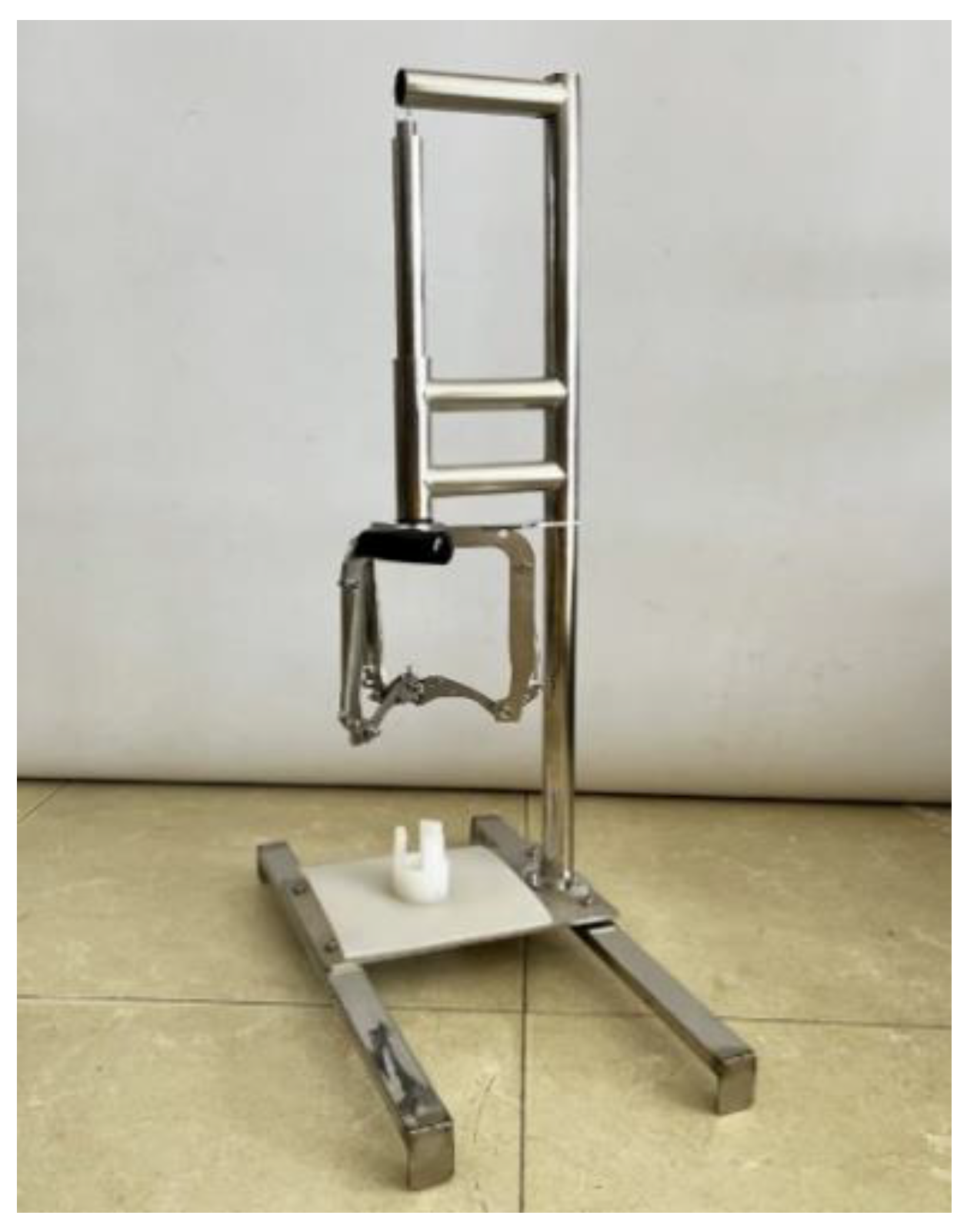
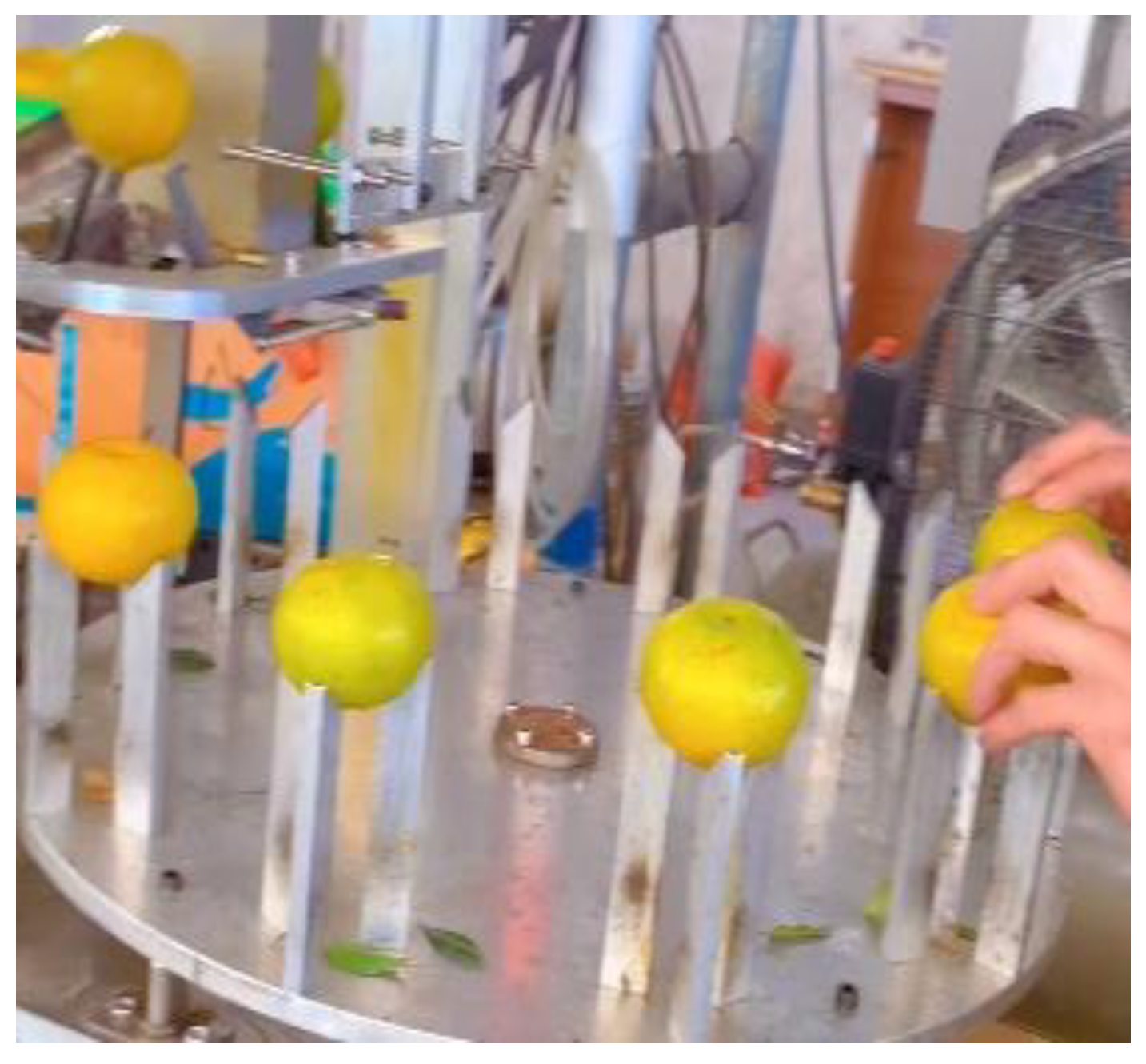
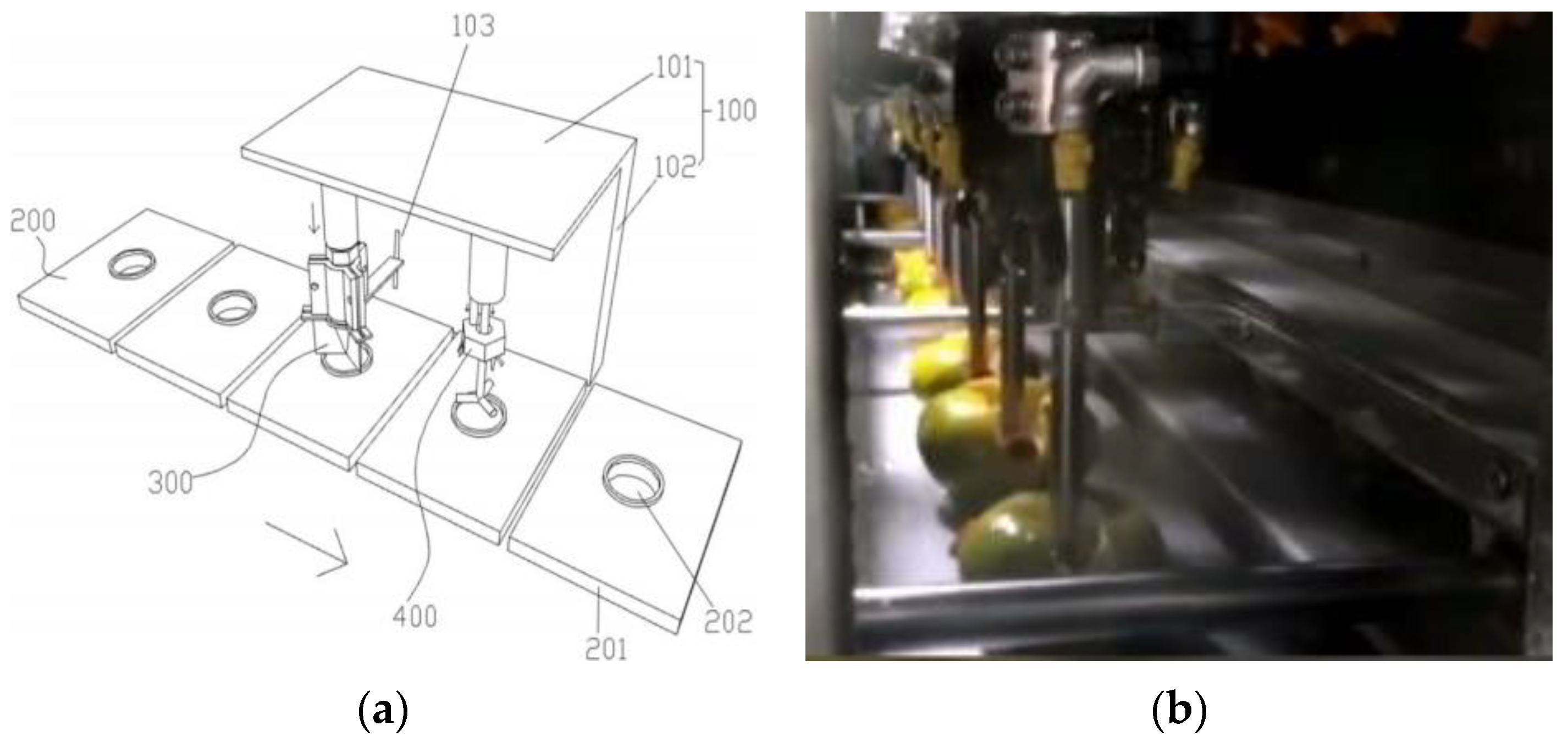
Therefore, semi-automatic cutting equipment for Citrus Reticulata ‘Chachi’ mainly relies on manual loading to accomplish stem identification and orientation adjustment. For example, a rapid cutting machine for Citrus fruits disclosed in a Chinese patent [24] (Figure 4) allows for the placing of the Citrus fruit on a base and the even pressing of the operating handle to cut the peel into three segments (tripetalous). The combined pneumatic–electric cutting machines designed by a local enterprise in Xinhui, Guangdong are shown in Figure 5. When working, one must manually load the Citrus Reticulata ‘Chachi’ onto a workstation and position the stem facing the correct orientation; then, an electric platform or turntable intermittently moves below the cutting knife, and the pneumatic-driven cutting knives moves downward to evenly cut the peel of Citrus Reticulata ‘Chachi’ into three segments (tripetalous). Another piece of equipment designed for the automatic separation of the Citrus peel and pulp, as disclosed in a Chinese patent [25], is shown in Figure 6; a conveyor belt, segmenting machine cylinder, and separating machine cylinder are all connected to a pneumatic controller, enabling the automatic batch segmentation of Citrus fruits and the separation of the peel and pulp. However, none of the mentioned equipment can automatically identify the stem and adjust the orientation of the fruit. All current equipment requires a human eye to recognize the stem and human personnel to manually load the fruit in the correct orientation, which directly impacts the efficiency and quality of initial processing. It is evident that automatic stem identification and fruit orientation adjustment before cutting are bottleneck issues restricting the full automation of the initial processing of Citrus Reticulata ‘Chachi’.
To adapt to the current production situation of the pericarp of the Citrus Reticulata ‘Chachi’ and fill the gap in modern intelligent equipment technology in fruit processing, this study focuses on a control method for the automatic stem identification and fruit orientation adjustment of Citrus Reticulata ‘Chachi’. A novel Citrus Reticulata ‘Chachi’ orientation adjustment mechanism (COAM) based on visual feedback guidance was designed. Through a visual feedback system, the coordinates of a stem can be obtained in real time, and the motion path of the stem adjustment can be planned and feedback-corrected in real time. This mechanism enables Citrus Reticulata ‘Chachi’ in any orientation to be quickly adjusted to the stem-up (or stem-down) position via the shortest path. The COAM can prevent stem damage, reduce the risk of tool damage, improve the efficiency of the initial processing of Citrus Reticulata ‘Chachi’, and ensure the quality of the pericarp of the Citrus Reticulata ‘Chachi’. The orientation adjustment process is fully automated, requiring no manual intervention, and can be easily integrated into industrial production lines, making subsequent peeling processes of Citrus Reticulata ‘Chachi’ simpler and more reliable.

2. The Working Principle and Structure Design of the COAM

2.1. Mechanical Structure Design

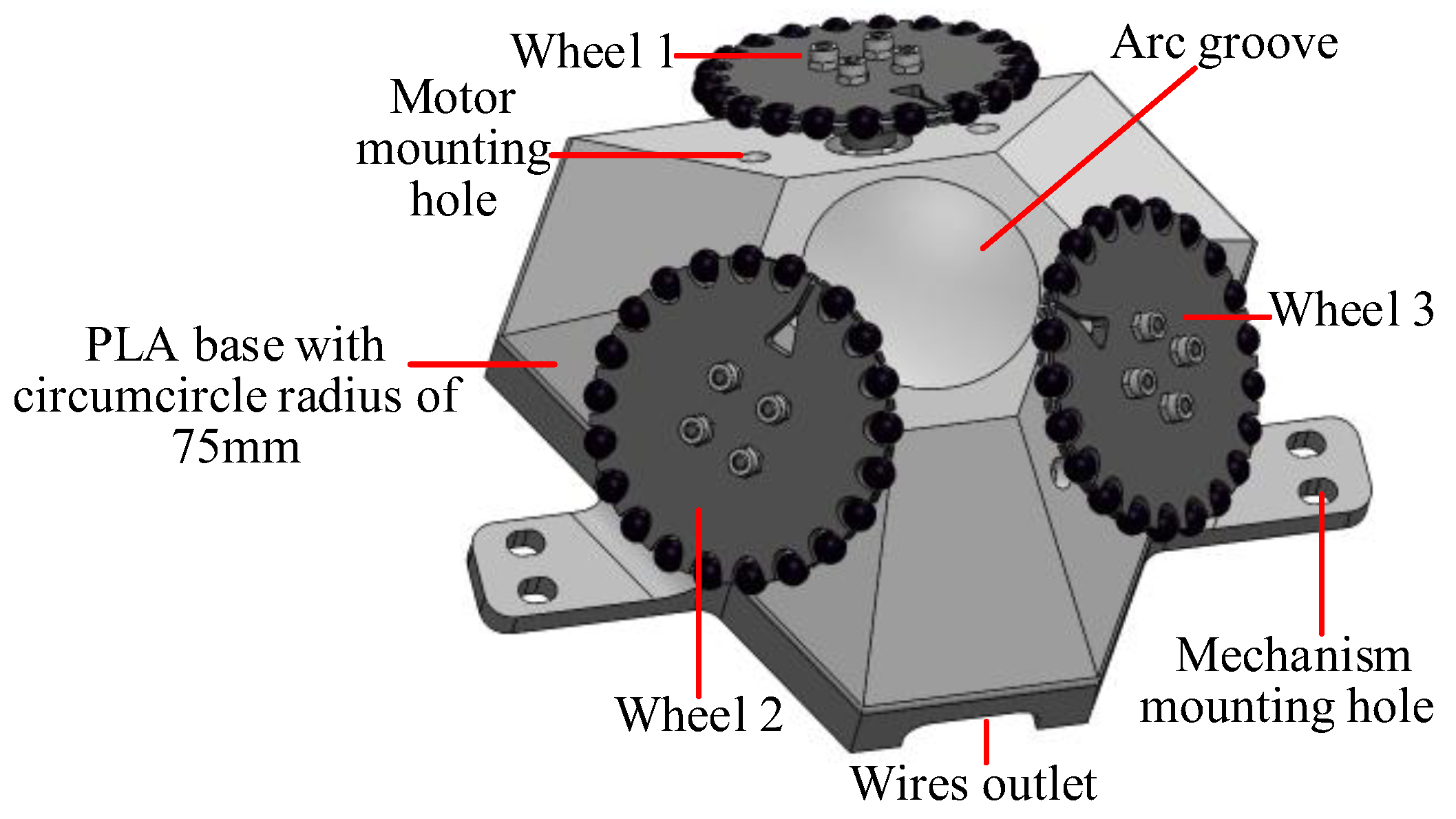
The mechanical structure design of the COAM is inspired by the ball-balancing robot. Utilizing a standard sphere (nylon) with a radius of R (35 mm) to simulate the spherical shape of Citrus Reticulata ‘Chachi’, the overall structure of the mechanism is shown in Figure 7. Viewed from above, the main body of the hexagonal structure is equipped with three symmetrically arranged omnidirectional friction-driven wheels, each one mounted on a pair of symmetric axes separated by 120°. The design of this three-wheel structure allows each individual wheel’s enveloping circle to have a contact point with the Citrus Reticulata ‘Chachi’, providing three rotational degrees of freedom in three-dimensional space. The shaft of each wheel is inclined at an angle of 30~60° with respect to the base of the mechanism to prevent the contact points of the three enveloping circles (R = 32 mm) from being too close. In this study, the angle between the wheel shaft and the base of the mechanism was set to 45° to ensure excellent omnidirectional rotation performance while achieving better motion control and stability. Additionally, symmetric motor mounting holes were designed on both sides of each individual wheel, and four mechanism mounting holes were designed on each side of the base for installation on different platforms. Wire outlets were also designed on the front and rear sides of the mechanism for cable routing.
The single-wheel structure of the COAM is shown in Figure 8. The single-wheel structure mainly consists of a stepper motor, flange shaft, shaft–wheel connecting joint, locking nut, and flexible rubber ball. The outer ring consists of 21 embedded flexible rubber balls (with a diameter of 6 mm) connected by iron wire and fixed in the outer ring’s grooves. The gap between these rubber balls is approximately 5 mm, providing the necessary flexibility and friction for the contact of Citrus Reticulata ‘Chachi’ and allowing the single wheel to have a larger enveloping circle than its radius. This arrangement also reduces the phenomenon of side-slipping when one or two wheels are rotating, thus achieving the decoupling of friction between the wheels.

2.2. Electronic Control System Design

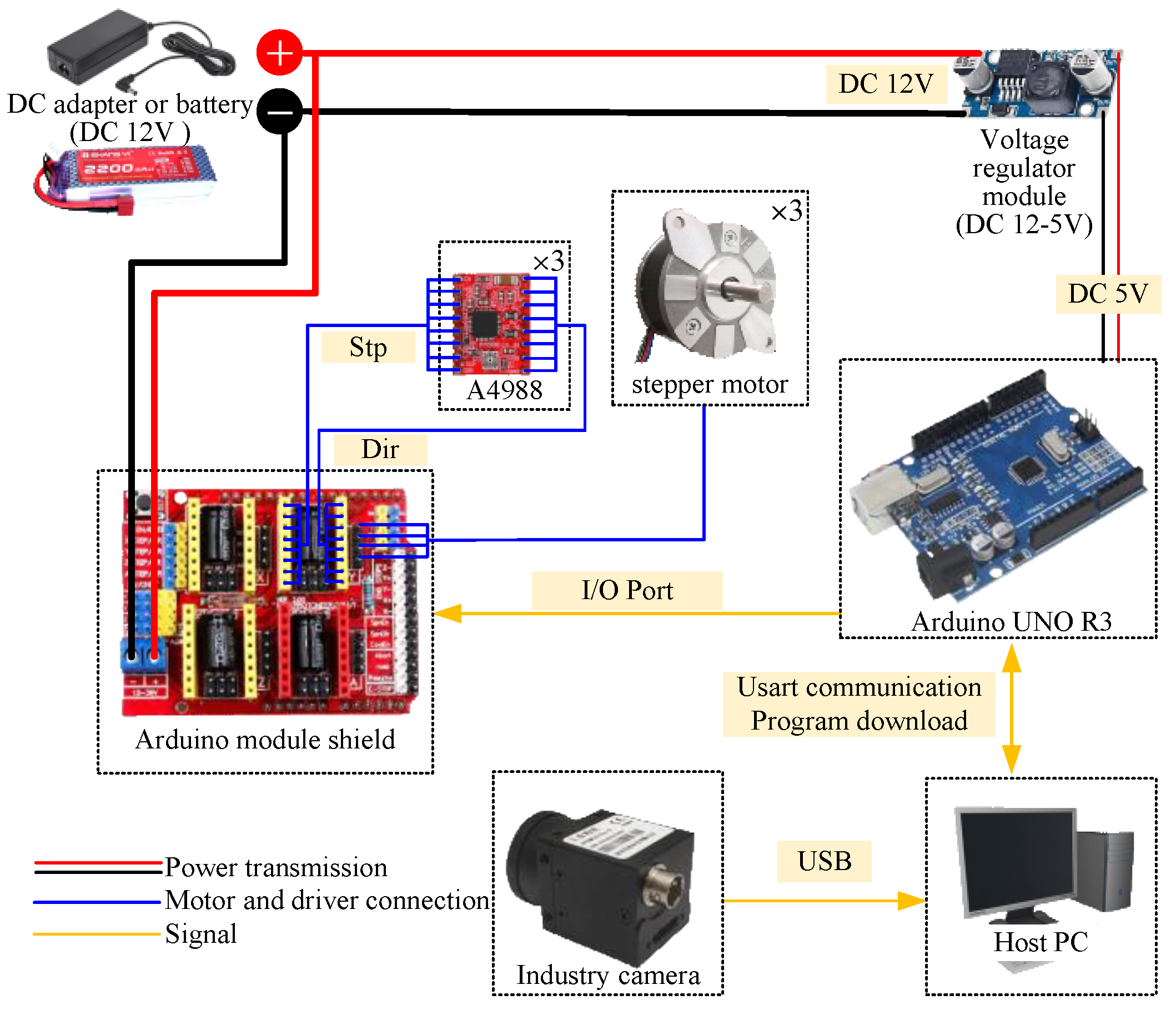
Each single-wheel structure requires a stepper motor for driving; thus, the control system of the COAM needed to be designed. The control system diagram shown in Figure 9 includes a power supply module, motor driver module, MCU module, host computer module, and visual feedback module.
The expansion board of the motor driver module contains three A4988 stepper motor driver boards (12VDC rated voltage, up to 16 micro steps) (Allegro Microsystems, Manchester, NH, USA) powered by a 12 V lithium battery or DC adapter. Additionally, the power is run through a 5 V DC voltage regulator module to supply power to the MCU module. The MCU module utilizes an Arduino UNO (Arduino.cc, Ivera, Italy) development board, which is responsible for sending direction and pulse signals to the expansion boards to control the position and direction of the three stepper motors. It also communicates with the host computer via USART for tasks such as program downloading and command sending. The LDO Nema14 36 mm Pancake Stepper Motors (Ldo Motors Co., Ltd., Shenzhen, China) (LDO-36STH20-1004AHG, 12VDC rated voltage, 1.8-degree step angle) on the single-wheel structure have a high torque, small volume, and light weight, and they are coaxially connected with every single wheel through the motor shaft. The industrial camera (Catchbest photoelectric equipment Co., Ltd., Beijing, China) connects to the host computer via USB and can displays real-time images. The host computer program was written in the C# language with the OpenCV-Sharp library; it calculates the stem coordinates through image processing algorithms and sends them to the MCU module in real time. Upon receiving the stem coordinates, the MCU module uses a kinematic inverse solution and feedback control algorithms to obtain control signals to the motors. These signals are then sent to the stepper motor drivers via I/O ports, thereby controlling the coordinated motion of the entire mechanism.

2.3. Principle of Mechanical Transmission

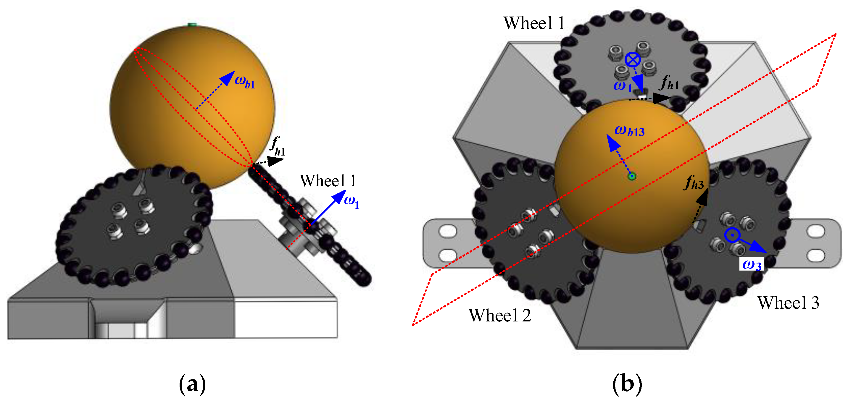
From Section 2.1, it can be inferred that the three single wheels of the COAM are connected to three stepper motors via flange shafts. The rotation of the stepper motors can drive the connected single wheels to rotate clockwise or counterclockwise in a plane perpendicular to the motor axis. As shown in Figure 10a, when only wheel 1 rotates counterclockwise, it generates an angular velocity ω1 right-hand rule along the direction of the motor axis, perpendicular to the maximum circular cross-section. At the contact point with the standard sphere, the flexible rubber balls on the enveloping circle of wheel 1 produce a friction force fh1, thereby driving the standard sphere to produce an angular velocity ωb1 in the direction perpendicular to the equatorial plane (tangent to the outer circle cross-section of wheel 1). This motion is like the meshing transmission of gears. Meanwhile, the flexible rubber balls on the enveloping circles of wheels 2 and 3 also experience lateral rolling at the contact points with the standard sphere, acting as passive elements to prevent slippage and thereby decoupling the friction forces between the three driving wheels and the standard sphere. As shown in Figure 10b, when wheel 1 rotates clockwise and wheel 3 rotates counterclockwise, they each generate angular velocities ω1 and ω3 along the direction of the motor axis, perpendicular to the maximum circular cross-section. The flexible rubber balls on the enveloping circles of wheels 1 and 3 each produce a friction force fh1 and fh3 at the contact points with the standard sphere, driving the standard sphere to produce an angular velocity ωb13 in the direction perpendicular to the plane dividing the two wheels by 120°. Meanwhile, the remaining small wheels on wheel 2 continue to roll laterally, serving as passive elements to prevent slippage.
Therefore, by combining the control of the three stepper motors, the standard sphere can be rotated to different degrees around the x, y, and z axes (3 DOFs), so standard sphere orientation adjustment can be realized.

2.4. Kinematic Modelling

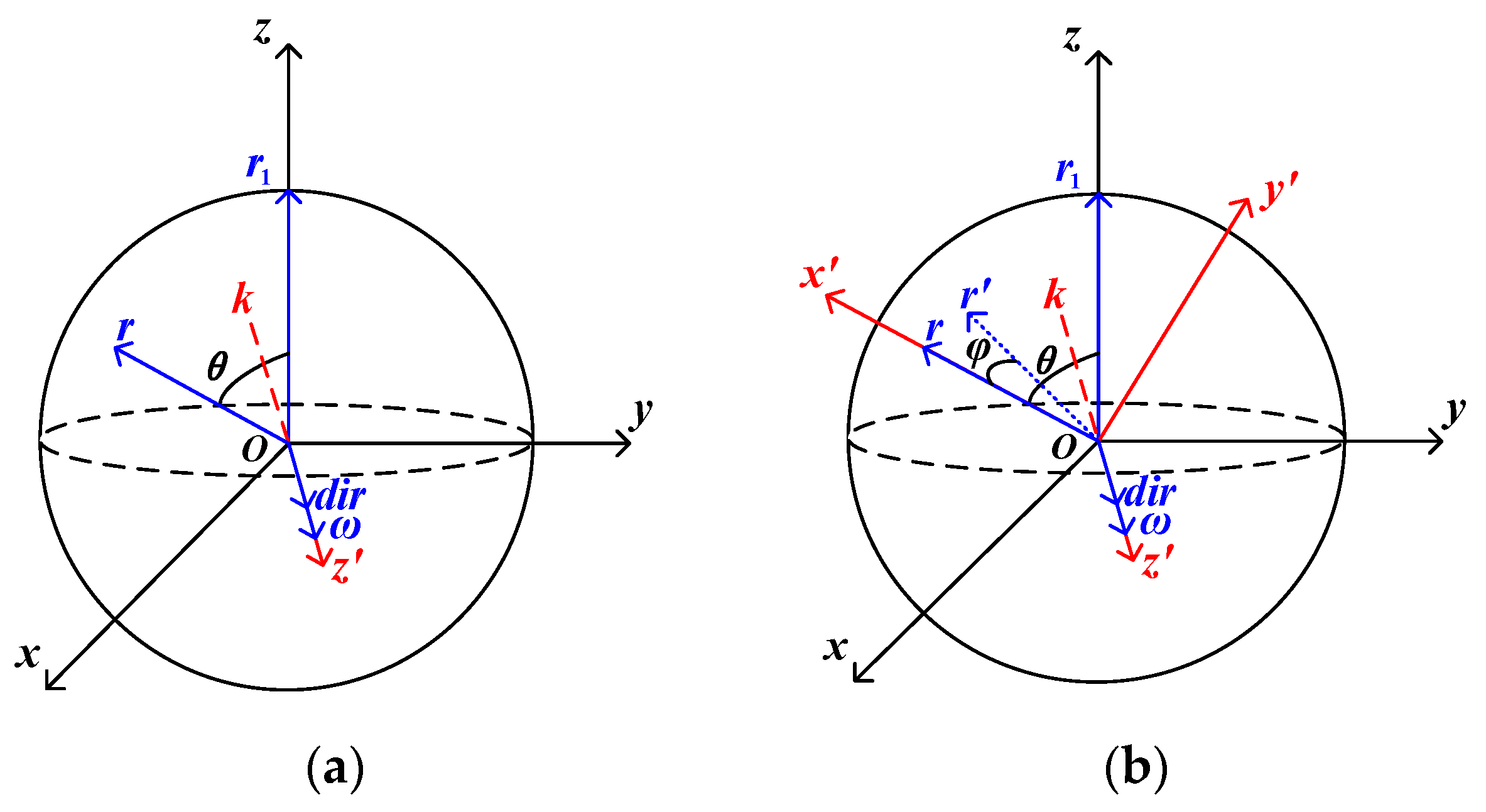
As shown in Figure 11a, a standard spherical coordinate system for Citrus Reticulata ‘Chachi’ was established.
In this system, the control position vector r(x,y,z) represents a vector pointing from the origin to an arbitrary position of the fruit stem, while the target position vector r1(0,0,R) points from the origin to the position where the fruit stem is upward. θ denotes the spatial angle between the control position vector r and the target position vector r1, and ω represents the composite angular velocity vector of the standard sphere coinciding with the rotation axis k. Essentially, to adjust the fruit stem from any position to an upright state, friction serves as the driving force. This involves controlling the Citrus Reticulata ‘Chachi’ to rotate around a rotation axis k synthesized in three-dimensional space, ensuring that the control position vector r aligns with the target position vector r1.
The rotation matrix for Citrus Reticulata ‘Chachi’ around the rotation axis k is as follows:
Rot ( k , θ ) = cos β cos γ cos β sin γ sin β sin α sin β cos γ + cos α sin γ sin α sin β sin γ + cos α cos γ sin α cos β cos α sin β cos γ + sin α sin γ cos α sin β sin γ + sin α cos γ cos α cos β
The coordinates of the control position vector r at a certain moment of rotation around the rotation axis k are as follows:
x t y t z t = cos β cos γ cos β sin γ sin β sin α sin β cos γ + cos α sin γ sin α sin β sin γ + cos α cos γ sin α cos β cos α sin β cos γ + sin α sin γ cos α sin β sin γ + sin α cos γ cos α cos β x y z
where α , β , γ represent the rotation angles of Citrus Reticulata ‘Chachi’ around the x, y, and z axes, respectively. As shown in Figure 11b, assuming the transformed new coordinate system is o-xyz’, where the z’ axis coincides with the rotation axis k, the z’ axis is aligned with the direction of the control position vector r, and y’ axis is perpendicular to the xo z’ plane, a coordinate transformation can be performed to simplify calculations. Then, the coordinate transformation matrix T is given by:
T = r r r × dir r × dir dir 3 × 3 = r r r × r × r 1 r × r 1 r × r × r 1 r × r 1 r × r 1 r × r 1 3 × 3
where dir is the unit directional vector of the z’ axis, aligned with the direction of ω , obtained by normalizing the cross product of the control position vector r and the target position vector r1. After combining (3) and r(x,y,z), in the new coordinates, the rotation of the standard sphere around the rotation axis k simplifies to rotation around the z’ axis. At a certain moment t, the coordinates of r rotating from r to r1 by angle φ around the rotation axis k simplify as follows:
x t y t z t = T × Rot z , φ × T 1 × r
where Rot z , φ = cos φ sin φ 0 sin φ cos φ 0 0 0 1 , the spatial angle is θ , the average angular velocity is ω , and the angle φ that r rotates towards r1 around the rotation axis k can be obtained with r, r1 and the total control time Δ t :
θ = a r cos r r 1 r r 1 = a r cos z R
ω = θ π 180 Δ t
φ = 180 ω t π = θ t Δ t
Therefore, by combining Equations (3)–(7), the coordinates of the control position vector r rotating around the rotation axis k towards r1 at each moment t can be obtained, allowing for subsequent sampling to record the adjustment trajectory of the standard sphere and the Citrus Reticulata ‘Chachi’ stem.
As shown in Figure 12, the three individual wheels of the COAM are labelled as wheel 1, wheel 2, and wheel 3. The origin Ob of the main body coordinate is located at the center of the bottom of the main body of the COAM, where Xb, Yb, and Zb, respectively, point to the right, front, and upward directions of the mechanism. The origins O1, O2, and O3 of the three individual wheel coordinates are located at the center of the wheel.
Taking wheel 3 as an example, the directional vector is as follows:
p 3 = 3 2 l cos ψ 1 2 l cos ψ l sin ψ Τ
where l represents the straight-line distance between the origin O3 of the wheel 3 coordinate and the origin Ob of the COAM global coordinate and ψ is the spatial angle between the wheel axis and the bottom surface. Similarly, the P1 and P2 direction vectors for wheel 1 and wheel 2, as well as the position matrix P for all three wheels, are as follows:
p 1 = 0 l cos ψ l sin ψ Τ
p 2 = 3 2 l cos ψ 1 2 l cos ψ l sin ψ Τ
P = p 1 p 2 p 3 = 0 3 2 l cos ψ 3 2 l cos ψ l cos ψ 1 2 l cos ψ 1 2 l cos ψ l sin ψ l sin ψ l sin ψ
The forward kinematic equations are as follows:
ω = ω x ω y ω z = PW = P ω 1 ω 2 ω 3 = ω 2 3 2 l cos ψ + ω 3 3 2 l cos ψ ω 1 l cos ψ ω 2 1 2 l cos ψ ω 3 1 2 l cos ψ ω 1 l sin ψ + ω 2 l sin ψ + ω 3 l sin ψ
Meanwhile, the input matrix W of the forward kinematic equations consists of the angular velocity vectors of the three individual wheels ω 1 , ω 2 , ω 3 and the output matrix ω represents the matrix of angular velocity vectors ω x , ω y , ω z generated by the standard sphere on the three coordinate axes. Derived from the forward kinematic equations, the inverse kinematic equations are as follows:
W = ω 1 ω 2 ω 3 = P 1 ω = 0 3 2 l cos ψ 3 2 l cos ψ l cos ψ 1 2 l cos ψ 1 2 l cos ψ l sin ψ l sin ψ l sin ψ 1 ω x ω y ω z
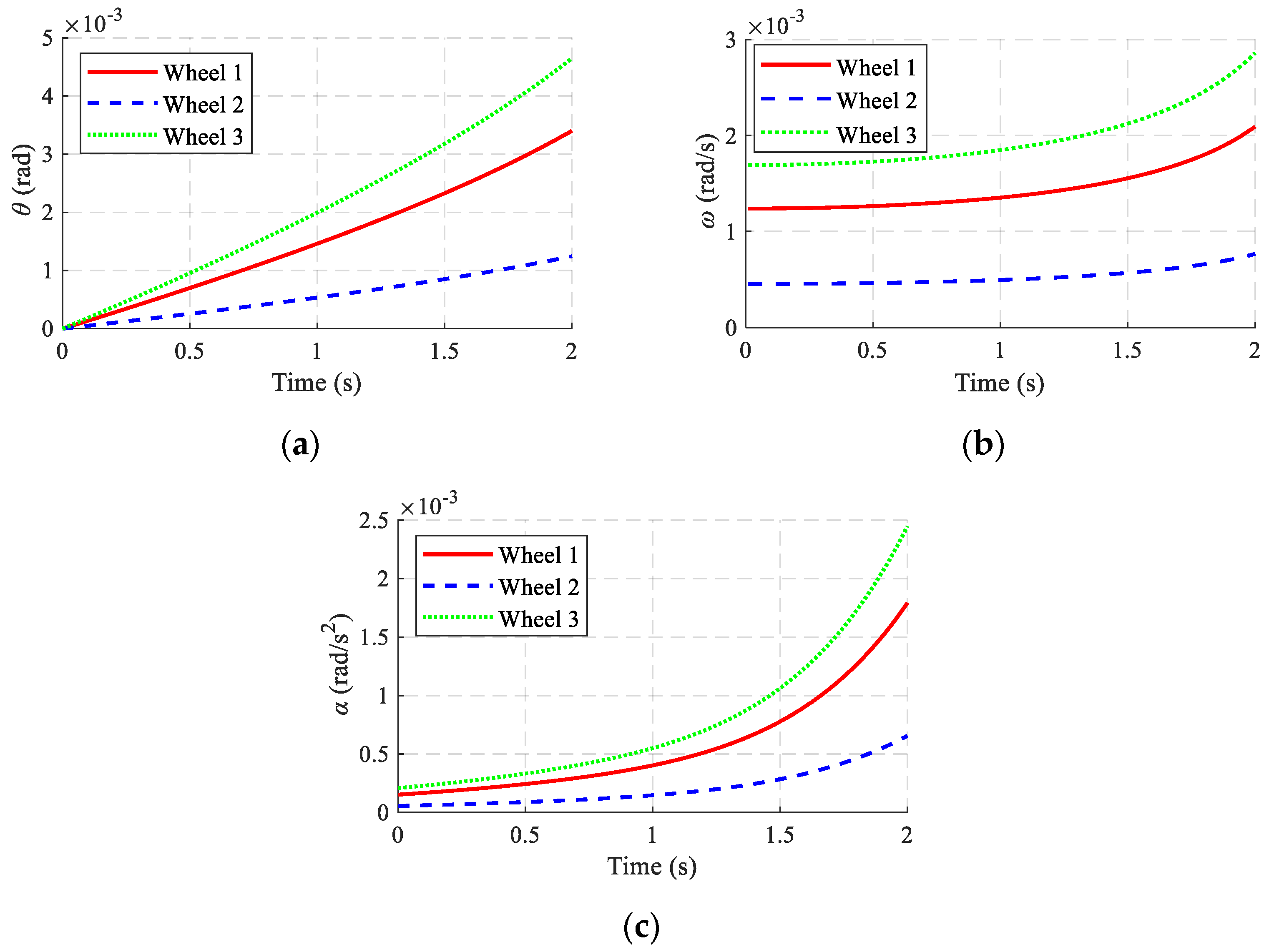
This establishes the forward and inverse kinematic models of the COAM, which was an essential step for the subsequent simulation examples and motion control experiment. The simulation parameters are shown in Table 1, where the line l was selected from the xoy plane, and the simulation results are shown in Figure 13.
Similarly, when selecting a circular trajectory C from the xoy plane, the simulation results were as shown in Figure 14.
The simulation results are shown in Figure 13 and Figure 14. It can be observed that under different trajectory scenarios, the motion patterns of the three individual wheels exhibited significant differences. When the motion trajectory of the COAM was a line, due to movement in only one direction, two of the wheels rotated at high angular velocities to facilitate differential motion, dominating the motion direction and angular velocity magnitude of the standard sphere’s motion. The remaining wheel, positioned farther from the direction of motion and approximately orthogonal to it, rotated at a lower angular velocity. Thus, utilizing flexible rubber balls on the side to act as passive components enabled the decoupling of frictional forces. Additionally, when the motion trajectory of the COAM was circular, the motion patterns of each wheel were similar, with a phase difference of 120°. The distance between each wheel’s position and the direction of motion varied over time, resulting in corresponding changes in the magnitude of their angular velocities.

3. Open-Loop Orientation Adjustment Experiment

3.1. The Experimental Platform Setup and Machine Vision Recognition

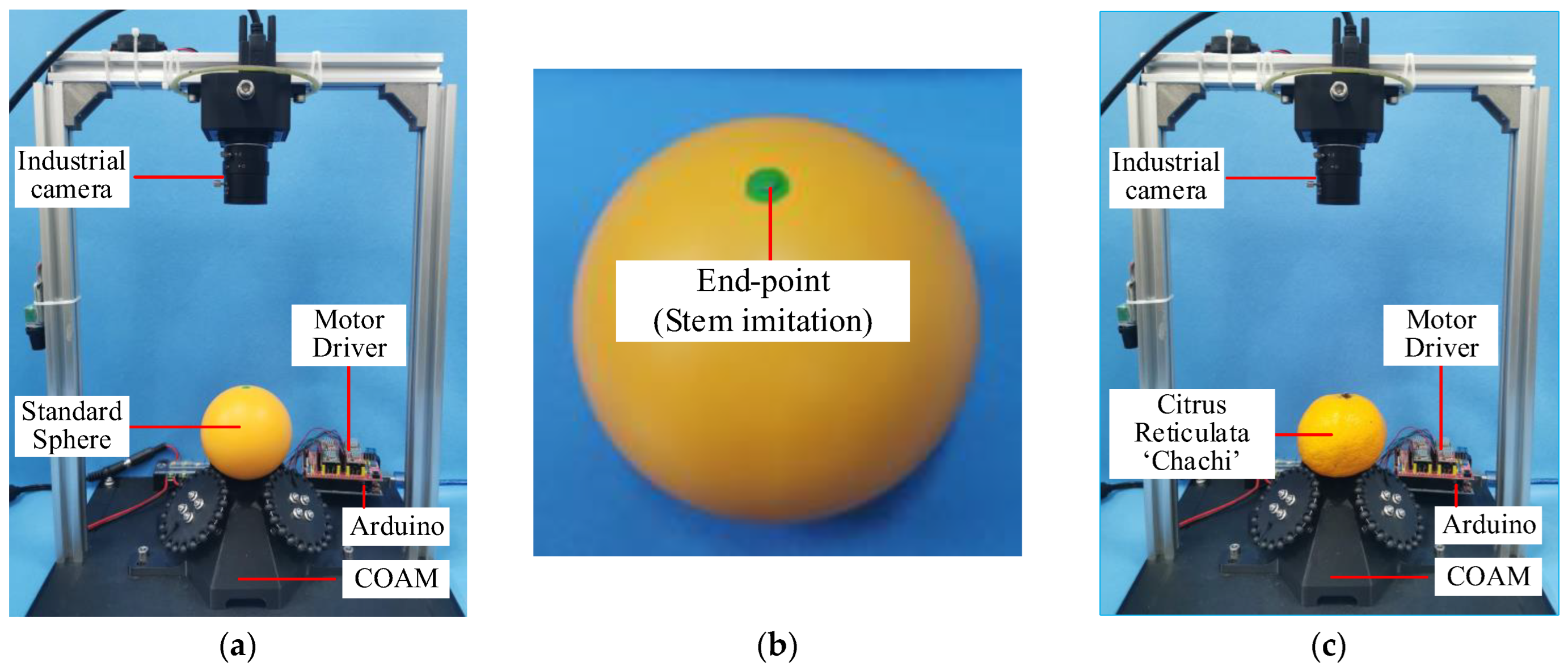
In Section 2.4, the kinematic model of the COAM was validated through simulation analyses using given line and circular trajectories. To further validate the correctness of the kinematic model, an open-loop orientation adjustment experiment was conducted using a standard sphere made of nylon on the constructed experimental platform. as shown in Figure 15a.
The radius of the standard sphere was equivalent to the average transverse radius of Citrus Reticulata ‘Chachi’ (35 mm), and its weight matched the average weight of Citrus Reticulata ‘Chachi’ (150 g). Additionally, to better match the look of Citrus Reticulata ‘Chachi’, the surface of the standard sphere was coated with orange matte paint. Furthermore, considering that the stem of the Citrus Reticulata ‘Chachi’ is dark green, a green marker was applied to simulate the position of the stem, serving as the end-point (Figure 15b). The trajectory of the end-point during the relevant motion processes was observed with an industrial camera.
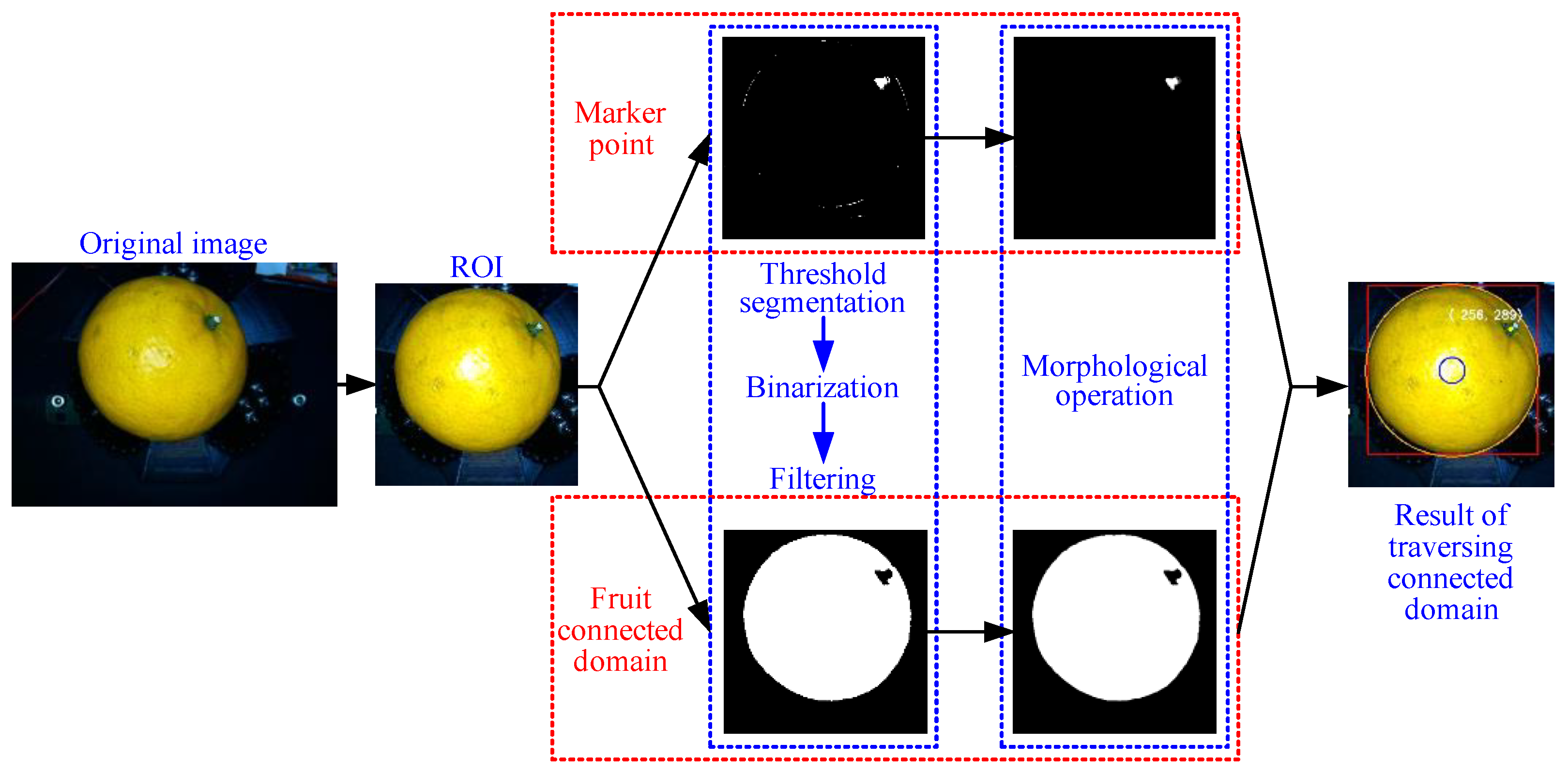
The first step of the visual guidance algorithm is stem identification. Stem identification mainly utilizes color threshold segmentation and connected component traversal methods. In this case, the overhead view imaging by an industrial camera separated the images of the standard sphere (or Citrus Reticulata ‘Chachi’) and the end-point (green marker point or dark green stem), which was projected onto the xoy plane. While marking the standard sphere (or Citrus Reticulata ‘Chachi’), the two-dimensional pixel coordinates of the end-point were extracted to calculate the inverse kinematics and closed-loop visual guidance algorithm. The orientation adjustment of the Citrus Reticulata ‘Chachi’ was based on its size, and its stem position was adjusted to near the center of its minimum circumscribed circle. This adjustment relied on a proportional relationship, so the image processing in this study was pixel-based and no additional calibration was required. As the determination of whether the end-point fell within the error circle (with a diameter of 10% of the pixel diameter of the minimum circumscribed circle of the standard sphere or Citrus Reticulata ‘Chachi’) was based on pixel proportions, camera coordinate transformation and pixel equivalence calibration were not required, making the process relatively simple. Figure 16 outlines the main steps of visual recognition when using the Citrus Reticulata ‘Chachi’. According to statistics, the diameter of the stem is in the range of 4~7 mm, assuming that the diameter of the Citrus Reticulata ‘Chachi’ is 65 mm, and the error band is set to 10% (that is 6.5 mm), which is within the diameter range of the stem; there is a small error as fault tolerance. Of course, in the actual use on a production line, this error band of 10% is a process parameter that can be adjusted according to actual working conditions. The larger the error band, the shorter the adjustment time, and the smaller the error band, the greater the adjustment time. In this paper, it was set to 10% because the diameter distribution of the Citrus Reticulata ‘Chachi’ is 65~70 mm most of the time, so it was reasonable to choose 10% as the error band.
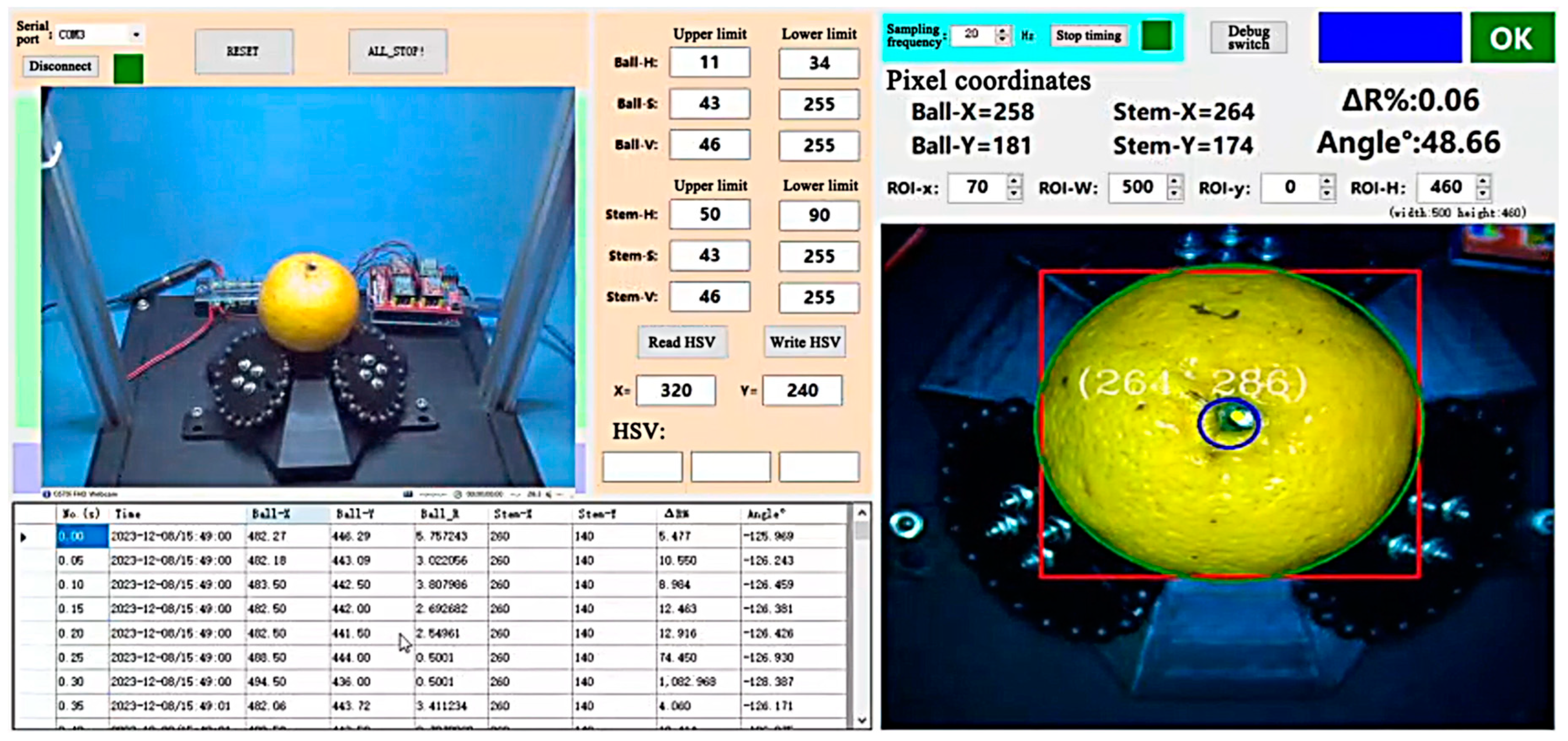
The host software interface programmed in the C# language (Figure 17) eventually displays the pixel coordinates of the end-point. This interface was integrated with the constructed experimental platform of the COAM, facilitating the recording and observation of subsequent experiments.

3.2. Open-Loop Orientation Adjustment Experiment with Standard Sphere

3.2.1. End-Point Trajectory Validation

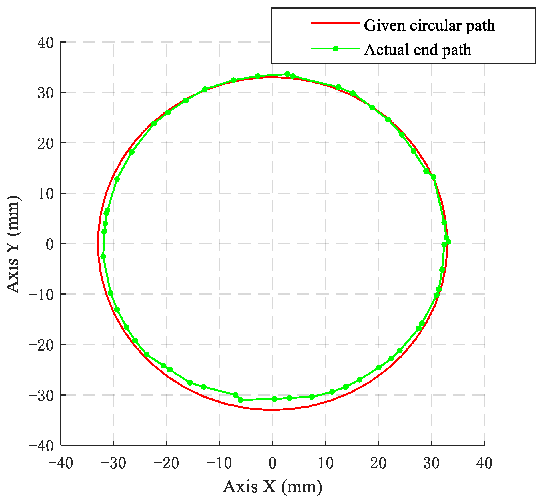
To validate the end-point trajectory, the circular trajectory in Table 1 was divided into 50 equal parts. Then, an inverse kinematics model was used to calculate the input vectors for each segmented trajectory of three driving wheels. These input vectors PW were then applied to the three individual wheels. The resulting actual end-point trajectory of the green marker point (simulating the fruit stem) on the standard sphere was compared with the given circular trajectory. As shown in Figure 18, the pixel equivalent was 0.214 millimeters per pixel. It can be observed that after applying the input vectors PW, the actual end-point path of the green marker point closely resembled the given circular path (the radius error was 2.03% and the Fréchet distance was 9.43). Thus, through the open-loop trajectory experiment, the correctness and feasibility of the inverse kinematic model were further validated.

3.2.2. Open-Loop Orientation Adjustment Experiment

After validating the kinematic model of the COAM in the previous chapters, based on the production requirements of cutting Citrus Reticulata ‘Chachi’ when fruit stems need to be adjusted to face upwards or downwards, an open-loop control experiment was conducted using a standard sphere to simulate the Citrus Reticulata ‘Chachi’. The end-point target was set as the center of the standard sphere projected onto the xoy plane.
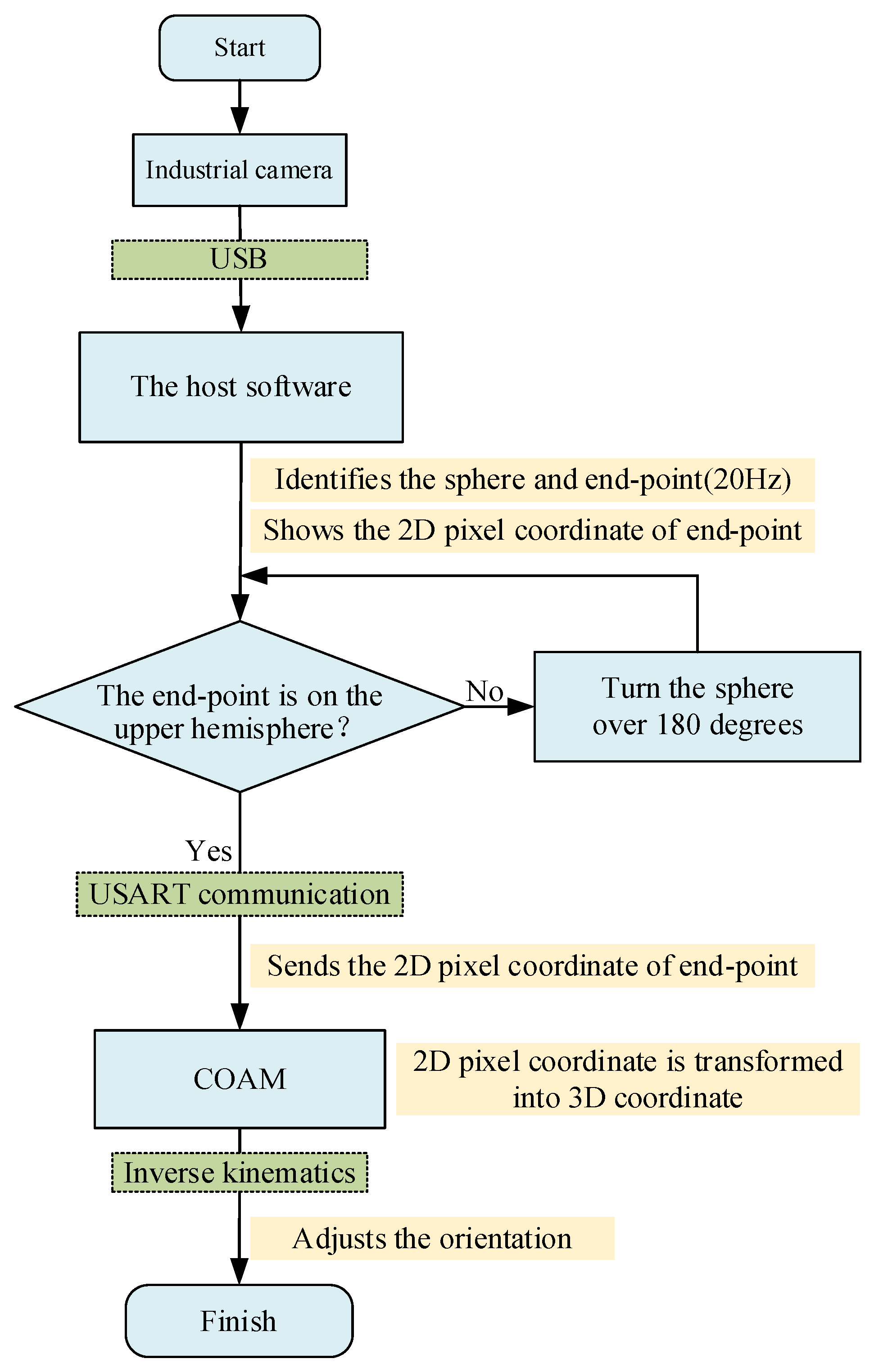
The experimental procedure, as shown in Figure 19, involved setting up an industrial camera positioned directly above the COAM to capture and identify the standard sphere and the end-point. If the camera failed to recognize the end-point, the host software instructed the COAM to flip the standard sphere 180 degrees upwards. Once the industrial camera detected the end-point during the overhead capture, it sent the two-dimensional pixel coordinates of the end-point projected on the xoy plane to the host software via USB. The host software used the USART protocol to communicate with the Arduino MCU and sent the two-dimensional pixel coordinates to it. The Arduino MCU running the COAM program first transformed the two-dimensional pixel coordinates back into three-dimensional coordinates and then calculated the rotation angles of the stepper motor shafts for the three individual wheels using the inverse kinematics model, thereby allowing the COAM to adjust the orientation of the standard sphere.
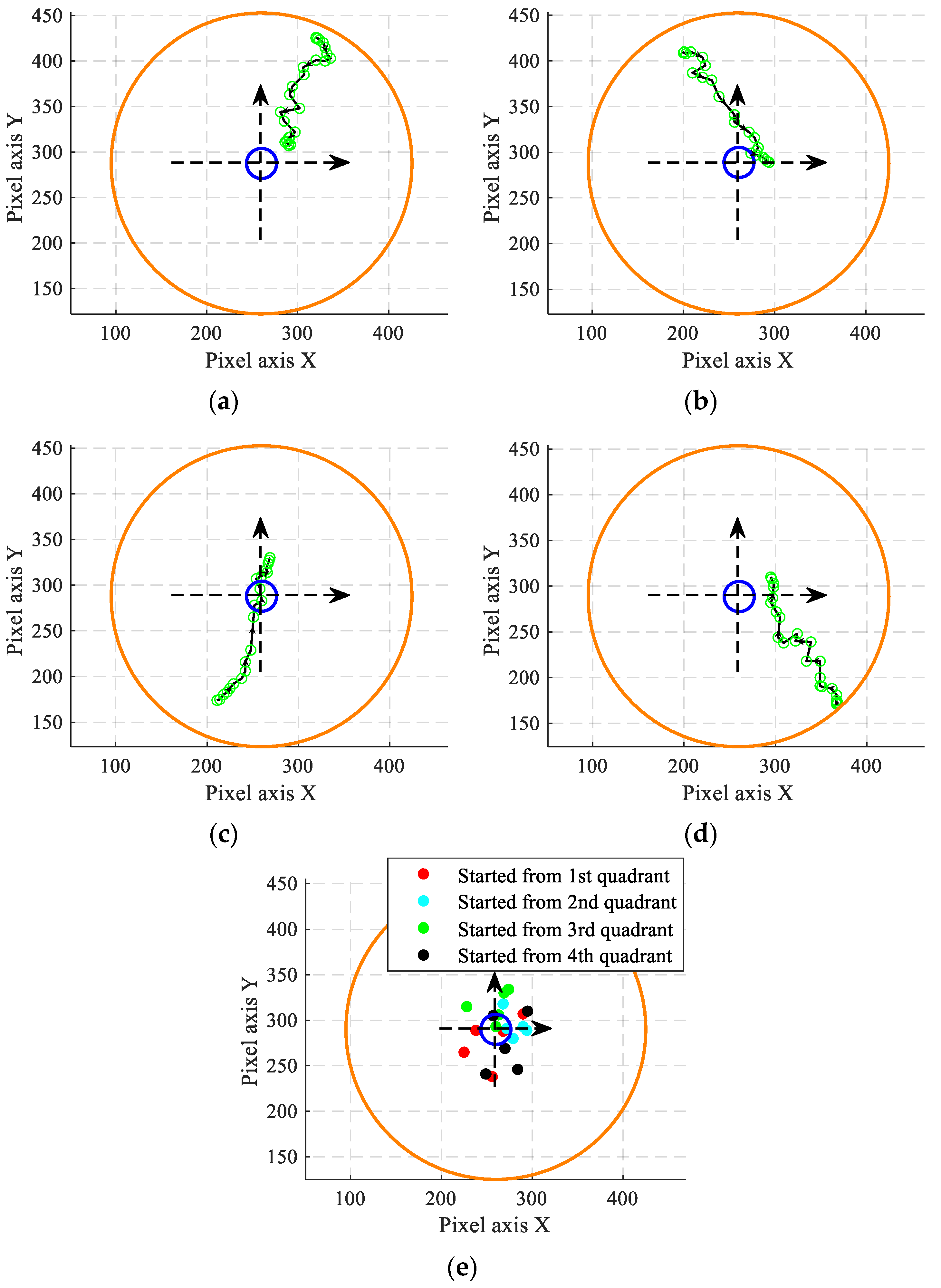
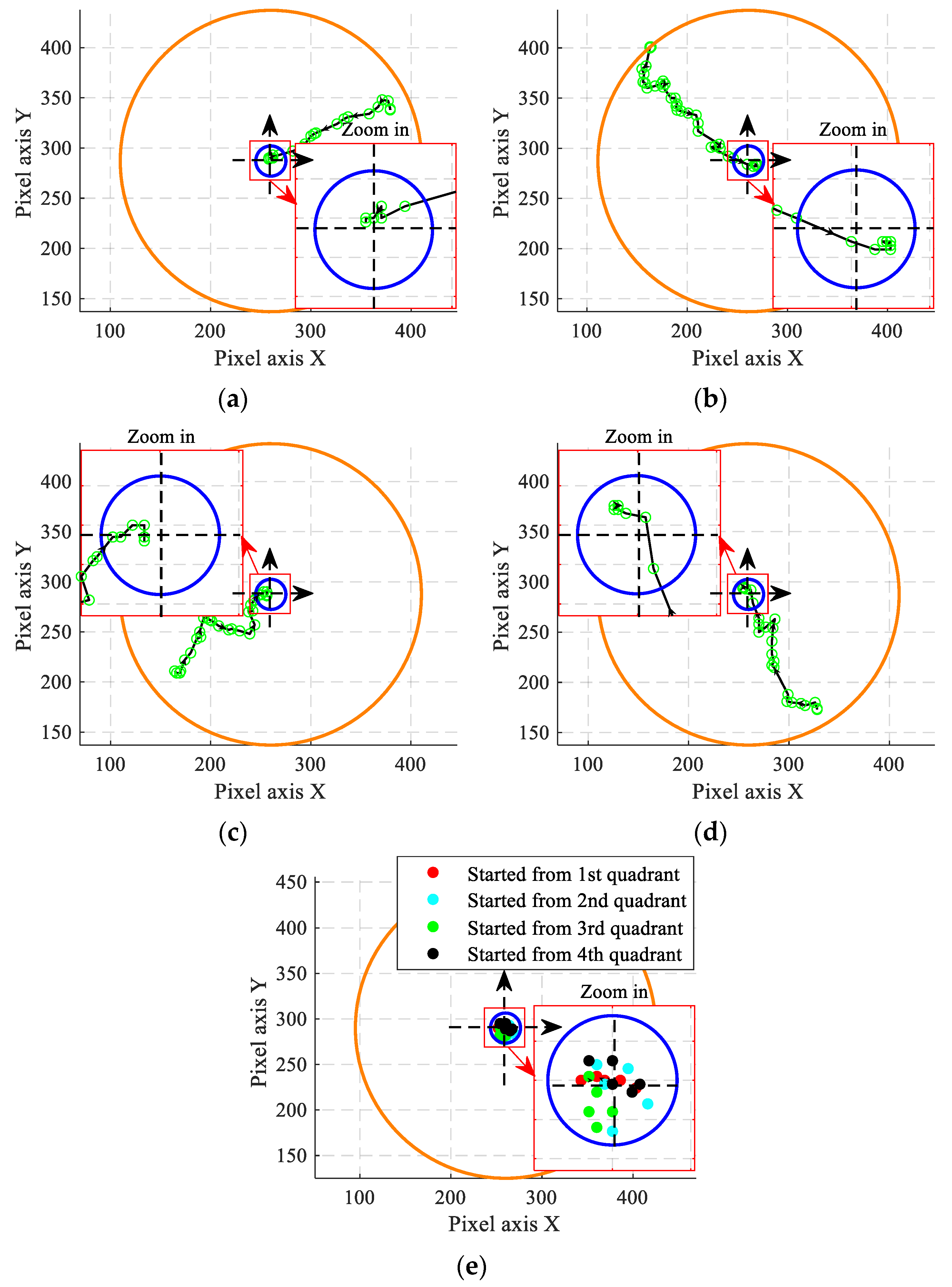
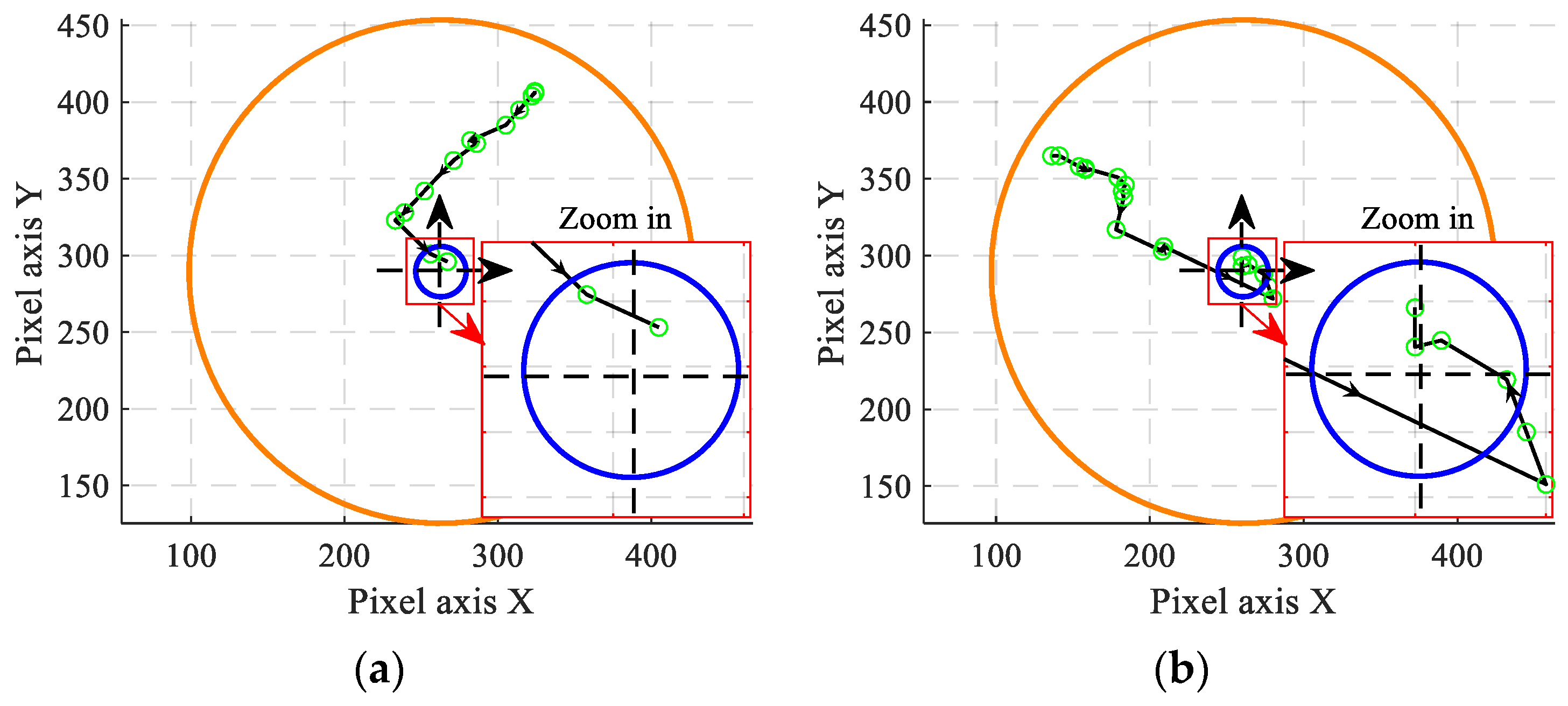
In the xoy plane (unit: pixel), with the center of the recognized circular region as the coordinate origin, five points were randomly selected from each quadrant as the starting points for the motion of the end-point. The open-loop control experiment for standard sphere orientation adjustment was then conducted. The paths of the end-point are shown in Figure 20a–d. The orange circles represent the projection of the standard sphere outline recognized by the industrial camera. The black lines connecting the green points represent the motion paths of the end-point recognized by the industrial camera. The black arrows on the lines indicate the direction of motion. The blue circles represent the error circle (within 10% of the standard sphere diameter) at the top center of the fruit.
Whether the end-point motion path could fall within the error circle under open-loop control was analyzed. According to Figure 20e, only about a quarter of the end-point paths ultimately fell within the error circle. The accuracy of orientation adjustment under open-loop control was not ideal because of machining accuracy and assembly errors, as well as uncertainties in friction. Relying solely on open-loop control made it difficult to achieve good adjustment results. Therefore, the COAM needed to introduce machine vision guidance algorithms with feedback control to improve the accuracy of orientation adjustment.

4. Closed-Loop Experiments with Different Algorithms

4.1. Closed-Loop Experiments Using PID Control

4.1.1. Standard Sphere Experiments (PID)

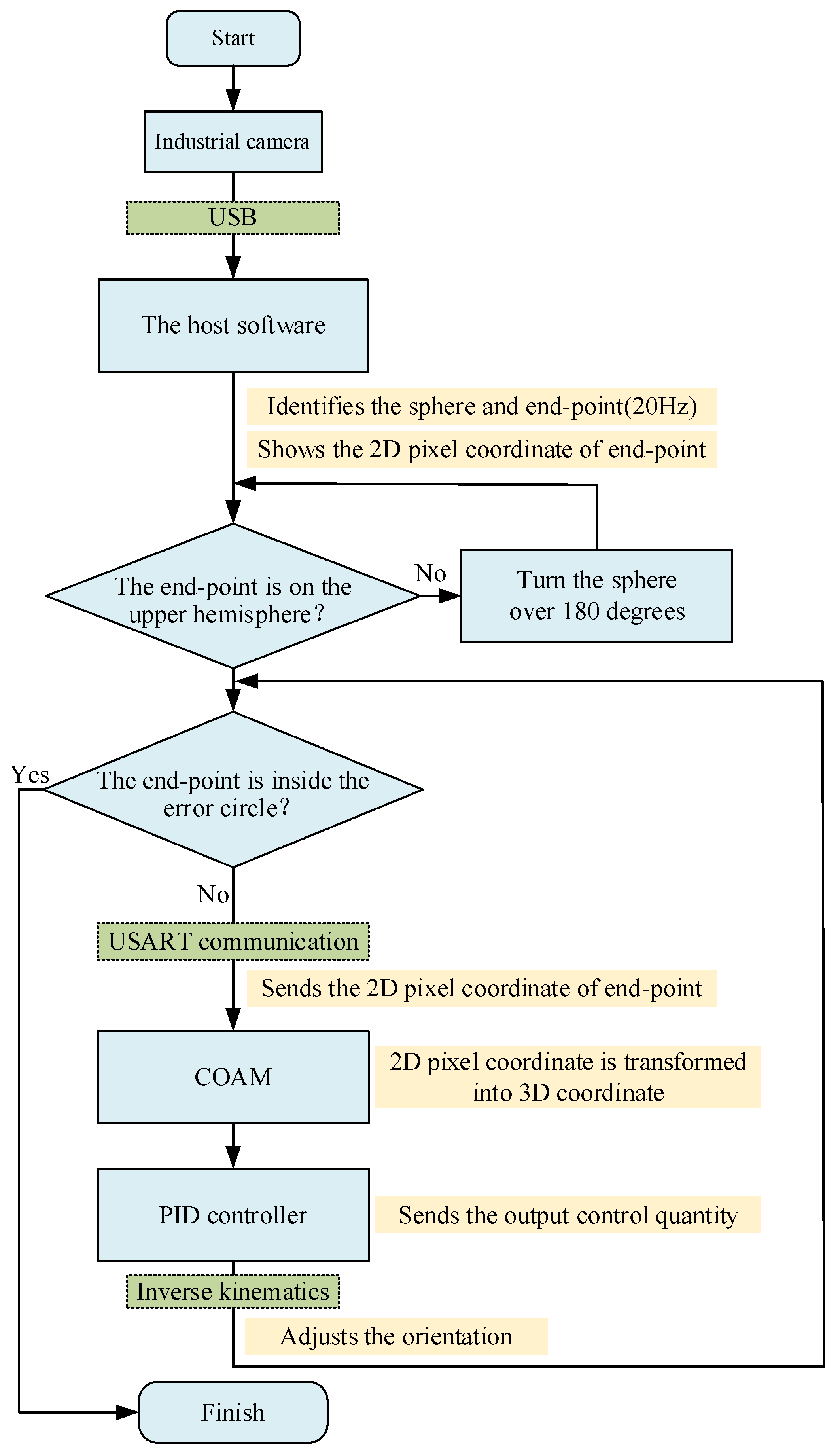
After conducting the open-loop control experiment, the visual guidance control experiment based on end-point coordinate feedback using the standard sphere was continued. The experimental procedure is shown in Figure 21. After each orientation adjustment, the host software evaluated the position of the end-point; if the end-point did not fall within the error circle, the COAM continued to correct the orientation of the standard sphere. During this process, the industrial camera identified the end-point at a frequency of 20 Hz until the end-point fell within the error circle.
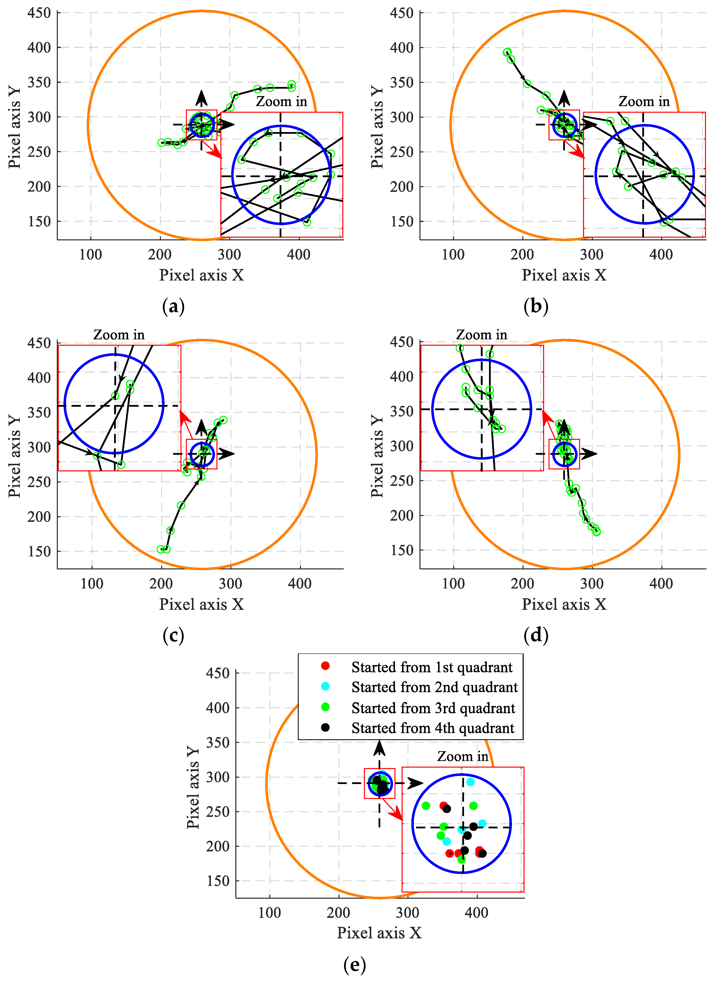
Similarly to the open-loop experiment, the paths of the end-point are shown in Figure 22a–d. To ensure consistency in the experiments, the standard remained the same as in the previous experiment, and it was observed whether the end-points of the path fell within the error circle under closed-loop control based on visual feedback control. From Figure 22e, it can be observed that after introducing visual feedback, the end-point of the standard sphere could eventually fall into the error circle no matter what quadrant it started from. The closed-loop control significantly improved the accuracy of orientation adjustment.
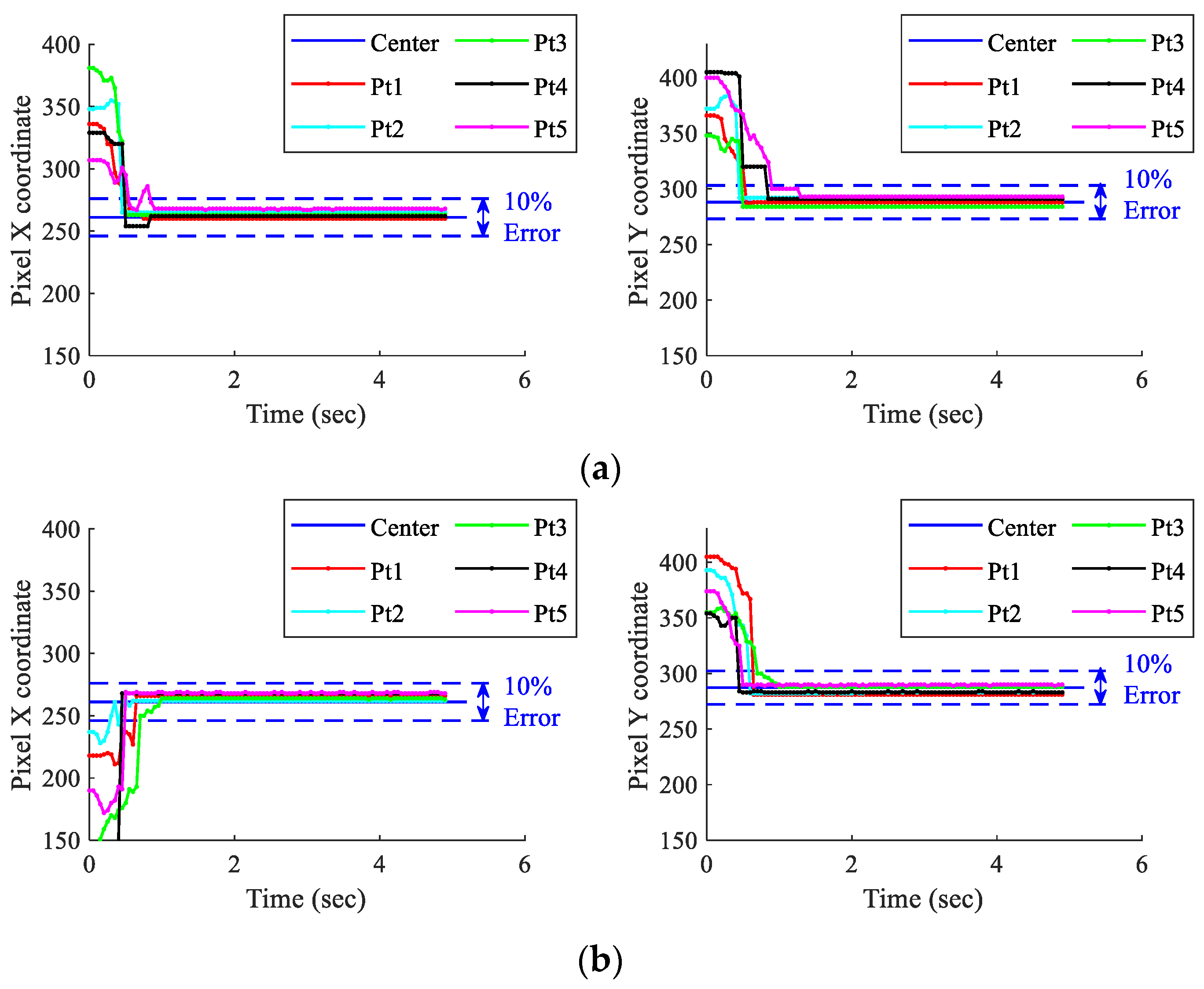
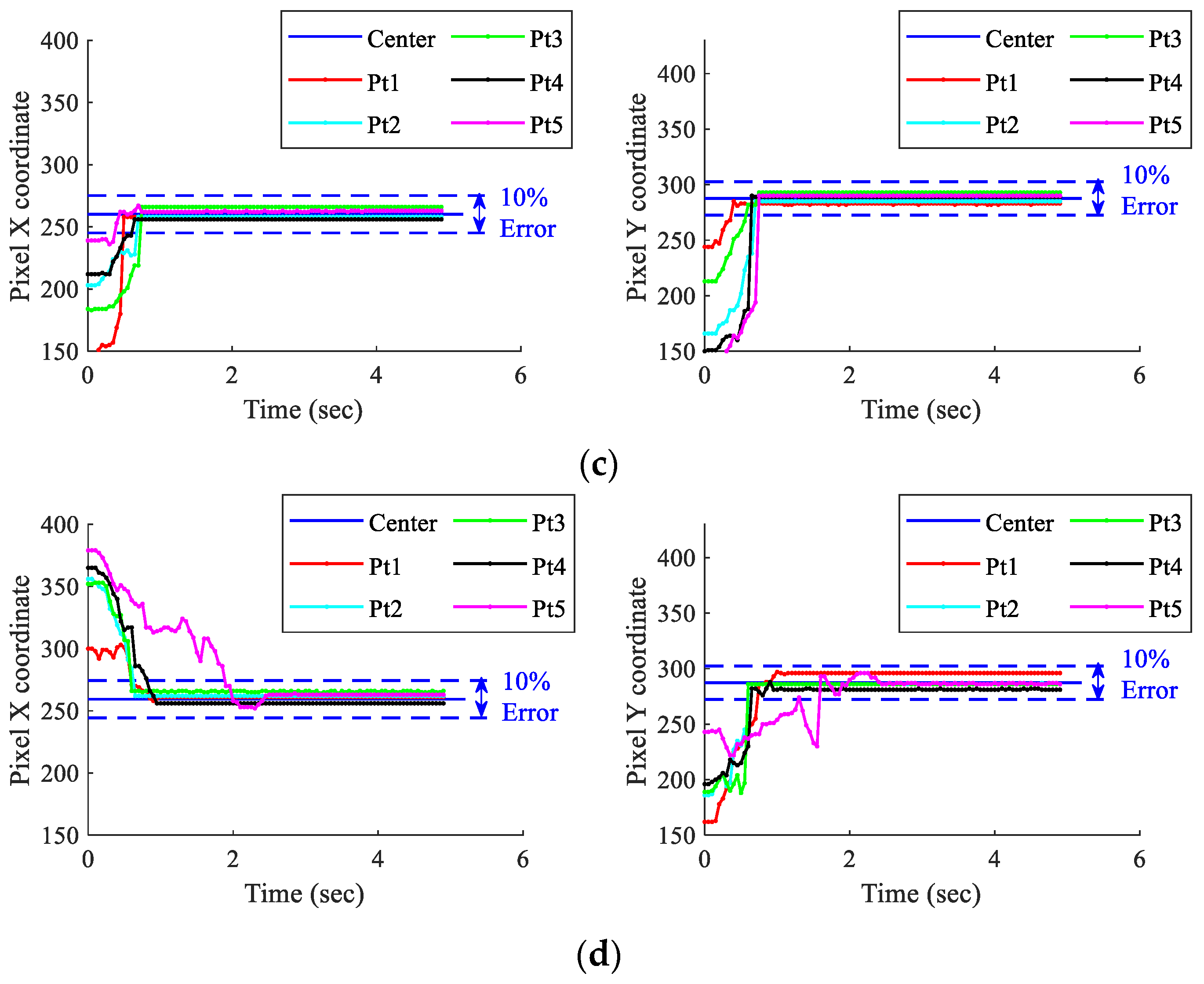
To evaluate the speed and stability of the closed-loop control with the standard sphere, further analysis was conducted on the five points’ trajectories selected from each quadrant. Time was set as the horizontal axis. The trends of pixels X and Y of the end-point during orientation adjustment from different quadrants were observed, as shown in Figure 23. While ensuring an error band of 10%, the pixel X and Y coordinates of the end-points tended to stabilize within 3 s. This indicates that under closed-loop control with visual feedback, the COAM exhibited a level of speed and stability that met the basic requirements for the initial processing and adjustment of Citrus Reticulata ‘Chachi’.

4.1.2. Citrus Reticulata ‘Chachi’ Experiments (PID)

To verify whether the COAM designed in this paper can be applied in actual production, a closed-loop control experiment was conducted using a fresh Citrus Reticulata ‘Chachi’. The experimental steps were like those shown in Figure 21 in Section 4.1, though the standard sphere shown in Figure 15a was replaced; the closed-loop experiment can be viewed on the following link: (https://www.youtube.com/watch?v=VxknxNjx85k, accessed on 1 September 2024).
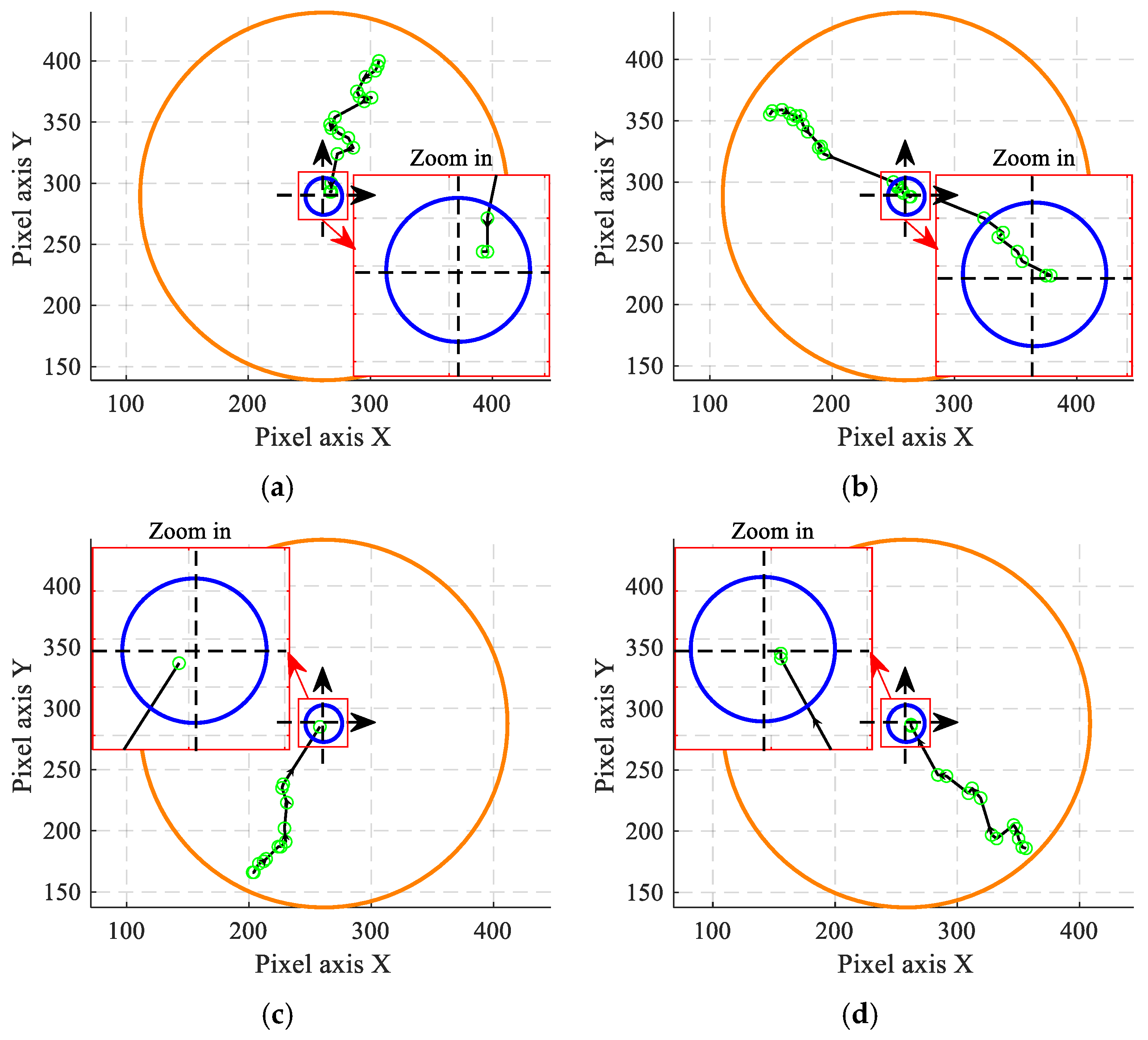
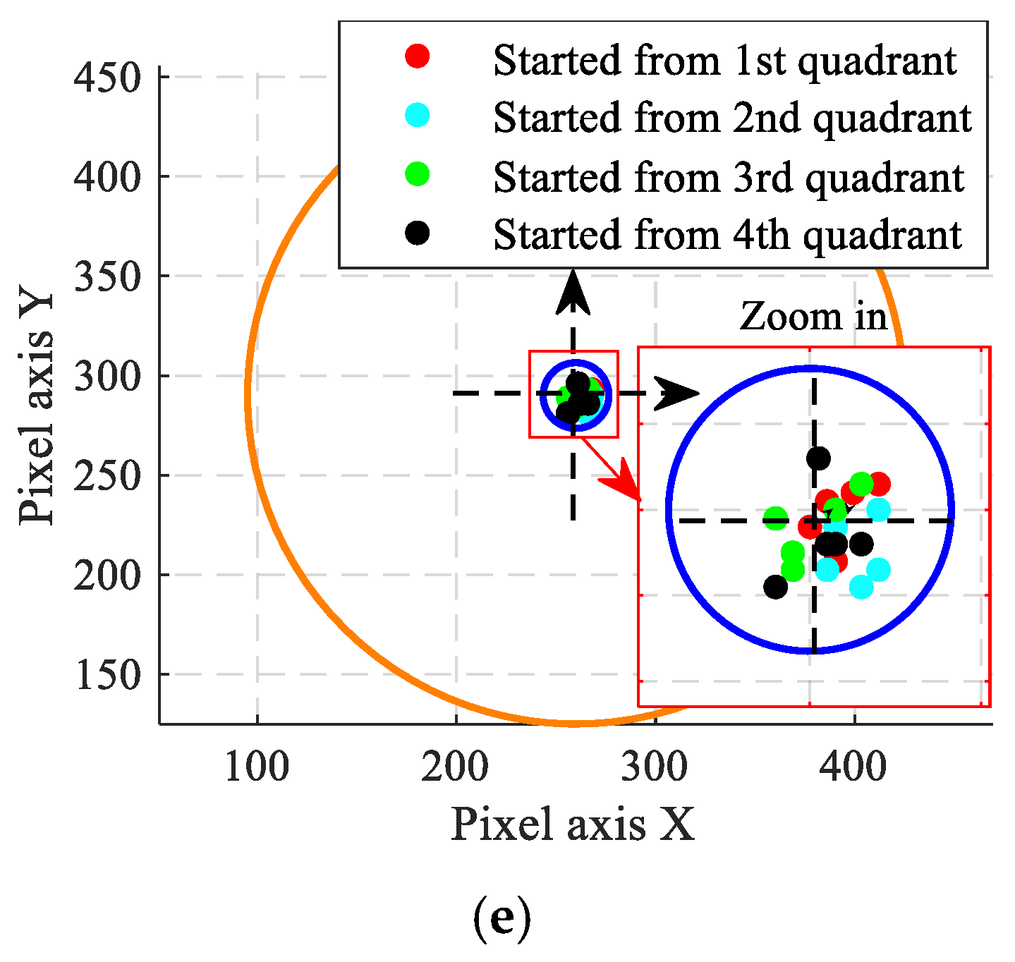
Some of the stem paths achieved following the previous steps are shown in Figure 24a–d. From Figure 24e, it can be observed that after introducing visual feedback, the dark green stem could eventually fall into the error circle, no matter what quadrant it started from. The orientation adjustment accuracy was comparable to the experiments using the standard sphere, indicating a similarly high level of accuracy. As shown in Figure 25, while ensuring the error band of 10%, the pixel X and Y coordinates of the stem tended to stabilize within 5 s. The rapidity and stability were comparable to the results with the standard sphere, meeting the basic requirements for the initial processing of Citrus Reticulata ‘Chachi’.

4.2. Closed-Loop Experiments Using LQR Control

4.2.1. Standard Sphere Experiments (LQR)

Although PID control was used to achieve desired adjustments, there was a lot of oscillation. Therefore, an LQR algorithm was used for improvement. Continuing to utilize standard spheres, the experimental procedure for vision-guided control based on LQR state feedback was as depicted in Figure 26.
Most of the steps were the same as in the previous PID experiments. The primary difference was the MCU program, as the LQR algorithm within the MCU program calculated the gain matrix K based on the system’s state-space expression and ultimately calculated the output control quantity u = −Kx provided by the LQR algorithm. This ensures that the system’s state optimally approaches zero in a fast and stable manner under given performance metrics, thereby achieving system stability. Firstly, consider the state-space representation of a linear time-invariant system:
x ˙ = A x + B u
where x is the state vector of the system and A and B are system matrices. The matrices A and B are as follows:
A = 0 6 4 6 4 2 2 2 4 2 4 2 2 2 2 2 2
B = 1 0 0 0 1 0 0 0 1
The performance criterion for the system is typically represented by a quadratic cost function:
J = 1 2 0 x T Q x + u T R u d t
where Q is a semi-positive definite diagonal matrix representing the state vector parameters and R is a positive definite diagonal matrix representing the control vector parameters. Substituting the linear state feedback controller u = −Kx into Equation (17) results in the following:
J = 1 2 0 x T Q + K T R K x d t
A common practice is to define an auxiliary constant matrix P such that
d d t x T P x = x T Q + K T R K x
Then, the Riccati algebraic equation is solved using MATLAB’s (MATLAB9.9, MathWorks, Natick, MA, USA) solver toolbox to obtain the value of the auxiliary constant matrix P.
A T P + P A + Q P B R 1 B T P = 0
where the matrices Q and R are obtained through an empirical fitting method:
Q = 0.8 0 0 0 0.8 0 0 0 0.8
R = 1 0 0 0 1 0 0 0 1
Combining Equations (20)–(22) results in the optimal state feedback gain matrix K:
K = R 1 B T P = 1.20 0.14 0.90 0.14 0.65 0.23 0.90 0.23 1.88
Finally, the output control quantity u that minimizes the cost function J can be obtained:
u = K x = R 1 B T P x
Substituting u = −Kx into Equation (14) results in the following:
x ˙ = A B K x
Using the MATLAB toolbox to solve the eigenvalues of the matrix ABK revealed that the real parts of the three eigenvalues were −0.52, −1.43, and −1.43. All three eigenvalues had negative real parts, indicating that this system under LQR control was asymptotically stable.
This output control quantity was then used in inverse kinematics to determine the angular displacements of the three stepper motors. After each adjustment of the orientation, the host computer assessed the position of the green marker point. If the green marker point remained outside the error circle, the COAM continued to correct the orientation of the standard sphere; the sample frequency remained at 20 Hz for results comparison.
The experimental data were recorded in the same way as in Section 4.1. The motion paths of some green marker points are depicted in Figure 27a–d. As shown in Figure 27e, incorporating state feedback resulted in the end-points of the motion paths of the green marker points, regardless of the starting quadrant, eventually falling within the error circle.
Using time as the horizontal axis, it was observed that the trends of the pixel X and Y coordinates of the end-points fit within the 10% error, as depicted in Figure 28. Furthermore, both the pixel X and Y coordinates of the end-points tended to stabilize within 2 s. These results indicate that the LQR state feedback exhibited certain levels of both speed and stability.

4.2.2. Citrus Reticulata ‘Chachi’ Experiments (LQR)

The control object of the standard sphere was then replaced by the Citrus Reticulata ‘Chachi’. The steps were the same as those described in Section 4.2.1, and the experimental data were also recorded in the same way. The motion paths of some green marker points are depicted in Figure 29a–d. Additionally, as shown in Figure 29e, regardless of the starting quadrant, the motion paths of the deep green stems, aided by state feedback, eventually fell within the error circle.
Using time as the horizontal axis, the trends of the pixel X and Y coordinates of the deep green stems of the Citrus Reticulata ‘Chachi’ during orientation adjustment motion as initiated from different quadrants were observed, as shown in Figure 30. It can be observed that, with the error maintained within 10%, both the pixel X and Y coordinates of the stem tended to stabilize within 2 s.

4.3. Results Comparison of Different Algorithms

To compare these two algorithms and ensure the universality of the COAM, this study repeated the above experiments using four Citrus Reticulata ‘Chachi’ fruits with sizes and weights close to the average (approximately 70 mm in long-axis size and 165 g). The experimental results of PID control showed that out of 80 trials conducted across the four quadrants with the four fruits, the average error of orientation adjustment was 3.93% (<10%) and the average stable adjustment speed was 15.64 mm/s (Table 2). Additionally, the experimental results of LQR control showed that out of 80 trials conducted across the four quadrants with the four fruits, the average error of orientation adjustment was 3.62% (<10%) and the average stable adjustment speed was 22.81 mm/s (Table 3). The stable adjustment speed can be calculated with the following formula.
v = p × x s p x e p 2 + y s p y e p 2 t
where p is the pixel equivalent (0.214 mm/pixel), xsp and ysp are the coordinates of the starting points, xep and yep are the coordinates of the end-points, and t is the stable adjustment time.
The experimental results show that the COAM control with two algorithms all met the actual production requirements for the initial processing of Citrus Reticulata ‘Chachi’ in terms of accuracy, stability, and speed. In terms of accuracy, the total average adjustment error of the LQR algorithm was slightly higher than that of PID control. However, in each quadrant with the circular domain center as the origin, the average adjustment errors of the two algorithms varied, showing similar levels of accuracy. In terms of speed, it is evident that both the total average adjustment speed and the average adjustment speed in each quadrant with the circular domain center as the origin were higher for the LQR algorithm compared with PID control. This indicates that the LQR algorithm has a faster response speed and better agility.
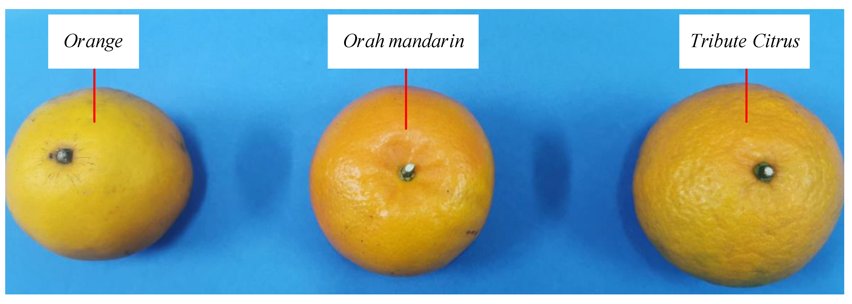
Furthermore, a corresponding closed-loop orientation adjustment experiment was conducted on other types of spherical fruits (Figure 31). The COAM could equally achieve fully automatic orientation adjustments for them, maintaining errors within 10% and demonstrating the strong universality of the COAM and the visual guidance control algorithm for other types of spherical fruits.

5. Conclusions and Outlook

To address the issues of low automation, poor efficiency, and standardization in the initial processing of Citrus Reticulata ‘Chachi’, this study innovatively designed a friction-driven Citrus Reticulata ‘Chachi’ orientation adjustment mechanism (COAM). Motion analysis and mechanical design were conducted, and open-loop experiments indicated that the mechanism could adjust the orientation of Citrus Reticulata ‘Chachi’ fruits of different sizes and weights, demonstrating strong adaptability. To improve the performance of the COAM, machine vision-based feedback was introduced in two different algorithms for visual guidance. The experimental results under closed-loop conditions showed that the COAM could adjust the Citrus Reticulata ‘Chachi’ stem along the shortest path. The mechanism could quickly and efficiently realize the automatic adjustment of some kinds of spherical fruits, and the LQR control was better than the PID control in both speed and precision. The COAM exhibited good stability and standardization, so it could become an indispensable part of the automation production line for the initial processing of Citrus Reticulata ‘Chachi’. The friction-driven Citrus Reticulata ‘Chachi’ orientation adjustment mechanism designed in this study can become an important step on the road to the mechanization and automation of the pericarp of the Citrus Reticulata ‘Chachi’ industry.

Author Contributions

Conceptualization, G.-Q.Y. and J.-S.M.; data curation, J.-Y.L. and Q.-S.C.; formal analysis, D.-Y.L.; funding acquisition, G.-Q.Y. and J.-S.M.; investigation, J.-Y.L.; methodology, G.-Q.Y. and J.-S.M.; resources, G.-Q.Y.; software, J.-Y.L. and Q.-S.C.; validation, G.-Q.Y., J.-S.M., D.-Y.L. and X.-E.Z.; writing—original draft, G.-Q.Y., J.-Y.L. and J.-S.M.; writing—review and editing, G.-Q.Y., Q.-S.C., D.-Y.L. and J.-S.M. All authors have read and agreed to the published version of the manuscript.

Funding

This work was funded and supported by the National Natural Science Foundation of China (Grant No. 52205266) and the Guangdong Basic and Applied Basic Research Foundation (Grant No. 2020A1515110191).

Institutional Review Board Statement

Not applicable.

Data Availability Statement

Data are contained within the article.

Conflicts of Interest

The authors declare no conflict of interest.

References

  1. Zhan, R.; Liu, J.; Chen, L.; Han, Z.; Lu, Y.; Chen, W.; Chen, W. Investigation on the Production Status of Lingnan Herbal Medicine in Guangdong Province. J. Guangzhou Univ. Treditional Chin. Med. 2020, 37, 1836–1843. [Google Scholar]
  2. Liu, W.; Wei, W.; Chen, Y.; Zhao, J.; Fu, M.; Wang, X. Research Progress on Geographical Origin Traceability and Authentication of Citri Reticulatae Pericarpium. Food Sci. 2023, 45, 19–28. [Google Scholar]
  3. Huang, J.; Li, M.; Wu, J.; Mo, Z. Current Situation and Development Countermeasures of Xinhui Citrus lndustry Planting. Guangdong Seric. 2023, 57, 112–114. [Google Scholar]
  4. China NPCO. Pharmacopoeia of the People’s Republic of China Part One; 2020 ed.; China Medical Science and Technology Press: Beijing, China, 2020. [Google Scholar]
  5. Wang, Y.; Fan, Q.; Wu, H.; Wang, J.; Liao, W. Textual Research on the Basic Source of Chenpi and a Brief Introduction to the Planting History of Medicinal Material. Subtrop. Plant Sci. 2023, 52, 453–464. [Google Scholar]
  6. Yu, X.; Sun, S.; Guo, Y.; Liu, Y.; Yang, D.; Li, G.; Lü, S. Citri Reticulatae Pericarpium (Chenpi): Botany, ethnopharmacology, phytochemistry, and pharmacology of a frequently used traditional Chinese medicine. J. Ethnopharmacol. 2018, 220, 265–282. [Google Scholar] [CrossRef] [PubMed]
  7. Shorbagi, M.; Fayek, N.M.; Shao, P.; Farag, M.A. Citrus reticulata Blanco (the common mandarin) fruit: An updated review of its bioactive, extraction types, food quality, therapeutic merits, and bio-waste valorization practices to maximize its economic value. Food Biosci. 2022, 47, 101699. [Google Scholar] [CrossRef]
  8. Singh, I.P.; Gore, D.D.; Karkhele, S.; Vairappan, C.S. The Chemistry and Pharmacology of Mandarin Orange (Citrus reticulata). In Recent Advances in Pharmaceutical Innovation and Research; Springer: Singapore, 2023; pp. 305–320. [Google Scholar]
  9. Liu, M.; Wang, J.; Deng, H.; Geng, L. Comparative study on main components and detection methods of Pericarpium Citri Reticulatae from different habitats. In IOP Conference Series: Earth and Environmental Science; IOP Publishing: Bristol, UK, 2021; p. 12018. [Google Scholar]
  10. Guan, X.; Yang, H.; Zhang, J.; Xu, J. Research Progress on Chemical Constituents and Pharmacological Effects of Tangerine Peel. Chin. Arch. Tradit. Chin. Med. 2023, 6, I0008. [Google Scholar]
  11. Liang, S.; Zhang, J.; Liu, Y.; Wen, Z.; Liu, X.; Dang, F.; Xie, T.; Wang, J.; Wang, Z.; Wu, H. Study on flavonoids and bioactivity features of pericarp of Citrus reticulata “Chachi” at different harvest periods. Plants 2022, 11, 3390. [Google Scholar] [CrossRef] [PubMed]
  12. Chen, Y.; Xu, Y.; Wen, J.; Yu, Y.; Wu, J.; Cheng, L.; Cheang, W.-S.; Liu, W.; Fu, M. Analysis of Flavonoid Metabolites in Citrus reticulata ‘Chachi’at Different Collection Stages Using UPLC-ESI-MS/MS. Foods 2023, 12, 3945. [Google Scholar] [CrossRef] [PubMed]
  13. Liang, P.; Chen, X.; Gong, M.; Xu, Y.; Tu, H.-S.; Zhang, L.; Liao, B.-S.; Qiu, X.-H.; Zhang, J.; Huang, Z.-H.; et al. Guang Chen Pi (the pericarp of Citrus reticulata Blanco’s cultivars ‘Chachi’) inhibits macrophage-derived foam cell formation. J. Ethnopharmacol. 2022, 293, 115328. [Google Scholar] [CrossRef] [PubMed]
  14. Yang, M.; Jiang, Z.; Wen, M.; Wu, Z.; Zha, M.; Xu, W.; Zhang, L. Chemical variation of Chenpi (Citrus peels) and corresponding correlated bioactive compounds by LC-MS metabolomics and multibioassay analysis. Front. Nutr. 2022, 9, 825381. [Google Scholar] [CrossRef] [PubMed]
  15. Lai, Y. The Utilization of Xinhui Chenpi Geographical lndication from the Perspective of Brand Premium. China Trademark 2023, S1, 70–73. [Google Scholar]
  16. Wang, M.; Li, X.; Ding, H.; Chen, H.; Liu, Y.; Wang, F.; Chen, L. Comparison of the volatile organic compounds in Citrus reticulata ‘Chachi’peel with different drying methods using E-nose, GC-IMS and HS-SPME-GC-MS. Front. Plant Sci. 2023, 14, 1169321. [Google Scholar]
  17. Yan, X.; Liu, J.; Zhang, F. Traditional Production Techniques and Quality ldentification of Xinhui Citri Reticulatae Pericarpium. Chin. Pharm. Aff. 2022, 36, 41–44. [Google Scholar]
  18. Zeng, H.; Zeng, L.; Chen, J.; Chen, X.; Peng, R.; Huang, Z.; Zeng, X.; Zeng, Z. Research Progress on Chemical Constituents Difference of Citri Reticulatae Pericarpium with Different Storage Years. Asia-Pac. Tradit. Med. 2023, 19, 221–225. [Google Scholar]
  19. Yan, G.; Chen, D.; Mo, J.; Qu, J.; Sun, Z. Experimental Study on Dynamic Characteristics of Moisture Content of Citrus reticulata ‘Chachi’. Mod. Agric. Equip. 2022, 43, 31–38. [Google Scholar]
  20. Li, Z. Drawing up a new blueprint for the development of the hundred-billion-dollar industry of chenpi. China Brand 2024, 1, 44–45. [Google Scholar]
  21. Zhang, K.; Si, X.; Zhao, J.; Li, Z.; Liu, H.; Guo, Q. Development of Phellinus Igniarius and Tangerine Peel Compound Beverage. Beverage Ind. 2023, 26, 67–72. [Google Scholar]
  22. Liu, Q.; Yan, G.; Qu, J.; Chen, D.; Zhang, D.; Shen, R. Current status and countermeasures of primary processing machinery technology for Citrus reticulata Blanco (Citrus reticulata ‘Chachi’). J. Chin. Agric. Mech. 2021, 42, 91–98. [Google Scholar]
  23. Yan, G.; Qu, J.; Ou, G.; Mo, J.; Zhong, C.; Chen, D.; Liu, Q.; Zhang, D. Current situation and countermeasures of drying and storage technology and equipment of Citrus reticulata ’Chachi’. J. South. Agric. 2021, 52, 2543–2553. [Google Scholar]
  24. Deng, M. A Rapid Peeling Machine for Citrus Fruits. ZL201721250809.5, 16 October 2018. [Google Scholar]
  25. Wu, G. One Type of Automatic Device for Separating the Peel and Pulp of Citrus Fruits. ZL201720212220.X, 1 May 2018. [Google Scholar]
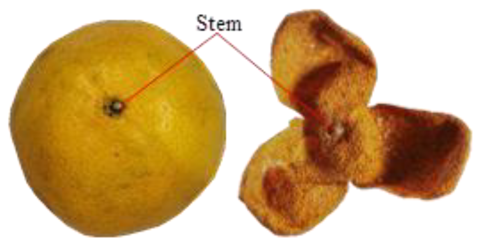
Figure 1. Citrus Reticulata ‘Chachi’ and the pericarp of the Citrus Reticulata ‘Chachi’.
Agriculture 14 01516 g001
Figure 2. Traditional production process of the pericarp of the Citrus Reticulata ‘Chachi’.
Agriculture 14 01516 g002
Figure 3. Different cutting methods of Citrus Reticulata ‘Chachi’. (a) Two cuts on the back; (b) three cuts on the front.
Agriculture 14 01516 g003
Figure 4. A manual cutting machine.
Agriculture 14 01516 g004
Figure 5. Manual loading with semi-automatic cutting machine.
Agriculture 14 01516 g005
Figure 6. A machine for Citrus cutting and peeling [25]. (a) Figure of patent file; (b) figure of real product.
Agriculture 14 01516 g006
Figure 7. The overall structure diagram of the COAM.
Agriculture 14 01516 g007
Figure 8. Single-wheel structure diagram.
Agriculture 14 01516 g008
Figure 9. The electronic control system diagram of the COAM.
Agriculture 14 01516 g009
Figure 10. Single wheel and double wheels drive standard sphere motion diagram. (a) Single wheel drives standard sphere; (b) double wheel drives standard sphere.
Agriculture 14 01516 g010
Figure 11. The sphere coordinates of Citrus Reticulata ‘Chachi’ and the motion process. (a) Coordinates of standard sphere; (b) coordinate transformation.
Agriculture 14 01516 g011
Figure 12. Reference coordinates for kinematic model. (a) Global coordinates; (b) single-wheel coordinates.
Agriculture 14 01516 g012
Figure 13. An inverse kinematics solution example of line trajectory. (a) Angular displacement; (b) angular velocity; (c) angular acceleration.
Agriculture 14 01516 g013
Figure 14. An inverse kinematics solution example of circular trajectory. (a) Angular displacement; (b) angular velocity; (c) angular acceleration.
Agriculture 14 01516 g014
Figure 15. The experimental setup. (a) Experimental platform with standard sphere; (b) standard sphere; (c) experimental platform with the Citrus Reticulata ‘Chachi’.
Agriculture 14 01516 g015
Figure 16. The main steps of stem identification.
Agriculture 14 01516 g016
Figure 17. Software interface (based on C# and OpenCV-Sharp).
Agriculture 14 01516 g017
Figure 18. Comparison between the actual end-point path and the given circular path (open-loop).
Agriculture 14 01516 g018
Figure 19. The flow chart of open-loop control.
Agriculture 14 01516 g019
Figure 20. Paths and end-point distributions of open-loop control experiment. (a) One of the paths in the first quadrant; (b) one of the paths in the second quadrant; (c) one of the paths in the third quadrant; (d) one of the paths in the fourth quadrant; (e) the end-points of the paths starting from different quadrants.
Agriculture 14 01516 g020
Figure 21. The flow chart of closed-loop control (PID control).
Agriculture 14 01516 g021
Figure 22. Paths and end-point distributions of PID control experiment (standard sphere). (a) One of the paths in the first quadrant; (b) one of the paths in the second quadrant; (c) one of the paths in the third quadrant; (d) one of the paths in the fourth quadrant; (e) the end-points of the paths starting from different quadrants.
Agriculture 14 01516 g022
Figure 23. The trends of pixels X and Y when the end-points started in different quadrants with time (standard sphere, PID control). (a) The trends of pixels X and Y starting from the first quadrant; (b) the trends of pixels X and Y starting from the second quadrant; (c) the trends of pixels X and Y starting from the third quadrant; (d) the trends of pixels X and Y starting from the fourth quadrant.
Agriculture 14 01516 g023
Figure 24. Paths and end-point distributions of PID control experiment (Citrus Reticulata ‘Chachi’). (a) One of the paths in the first quadrant; (b) one of the paths in the second quadrant; (c) one of the paths in the third quadrant; (d) one of the paths in the fourth quadrant; (e) the end-points of the paths starting from different quadrants.
Agriculture 14 01516 g024
Figure 25. The trends of pixels X and Y when the end-points started in different quadrants with time (Citrus Reticulata ‘Chachi’, PID control). (a) The trends of pixels X and Y starting from the first quadrant; (b) the trends of pixels X and Y starting from the second quadrant; (c) the trends of pixels X and Y starting from the third quadrant; (d) the trends of pixels X and Y starting from the fourth quadrant.
Agriculture 14 01516 g025
Figure 26. The flow chart of closed-loop control (LQR control).
Agriculture 14 01516 g026
Figure 27. Paths and end-point distributions of LQR control experiment (standard sphere). (a) One of the paths in the first quadrant; (b) one of the paths in the second quadrant; (c) one of the paths in the third quadrant; (d) one of the paths in the fourth quadrant; (e) the end-points of the paths starting from different quadrants.
Agriculture 14 01516 g027aAgriculture 14 01516 g027b
Figure 28. The trends of pixels X and Y when the end-points started in different quadrants with time (standard sphere, LQR control). (a) The trends of pixels X and Y starting from the first quadrant; (b) the trends of pixels X and Y starting from the second quadrant; (c) the trends of pixels X and Y starting from the third quadrant; (d) the trends of pixels X and Y starting from the fourth quadrant.
Agriculture 14 01516 g028aAgriculture 14 01516 g028b
Figure 29. Paths and end-point distributions of LQR control experiment (Citrus Reticulata ‘Chachi’). (a) One of the paths in the first quadrant; (b) one of the paths in the second quadrant; (c) one of the paths in the third quadrant; (d) one of the paths in the fourth quadrant; (e) the end-points of the paths starting from different quadrants.
Agriculture 14 01516 g029aAgriculture 14 01516 g029b
Figure 30. The trends of pixels X and Y when the end-points started in different quadrants with time (Citrus Reticulata ‘Chachi’, LQR control). (a) The trends of pixels X and Y starting from the first quadrant; (b) the trends of pixels X and Y starting from the second quadrant; (c) the trends of pixels X and Y starting from the third quadrant; (d) the trends of pixels X and Y starting from the fourth quadrant.
Agriculture 14 01516 g030aAgriculture 14 01516 g030b
Figure 31. Other spherical fruits.
Agriculture 14 01516 g031
Table 1. Simulation parameters.
Sphere Radius/mmWheel Radius/mmLine Trajectory/mmCircular Trajectory/mm
3525 l : x t = 10 t y t = 10 t C : x t = 33 cos 2 π t y t = 33 sin 2 π t
Table 2. The experimental results of four Citrus Reticulata ‘Chachi’ fruits (PID control).
Numbers of Citrus Reticulata ‘Chachi’ and Points1st Quadrant2nd Quadrant3rd Quadrant4th Quadrant
Error
(%)
Speed
(mm/s)
Error
(%)
Speed
(mm/s)
Error
(%)
Speed
(mm/s)
Error
(%)
Speed
(mm/s)
No.1
(70.90 mm in long-axis size,
166.78 g)
Point 13.8311.754.1218.317.5513.624.6218.17
Point 22.6119.821.8117.164.4314.704.5818.01
Point 38.9117.041.4916.676.3719.984.8315.97
Point 48.7417.046.8111.652.5211.733.4512.95
Point 55.0710.452.3715.105.7416.206.3217.64
No.2
(70.55 mm in long-axis size,
164.52 g)
Point 11.8119.237.8613.140.859.841.7011.07
Point 28.7314.632.3015.836.3714.300.6816.65
Point 32.2412.652.6515.732.4118.631.5415.89
Point 44.6916.691.1716.031.2813.980.2115.26
Point 50.9421.583.5517.235.8010.268.5214.67
No.3
(69.56 mm in long-axis size,
165.22 g)
Point 15.1112.778.4317.632.4014.521.9815.69
Point 23.2416.071.3520.424.2511.991.2518.54
Point 32.8918.162.5917.604.8317.104.6312.51
Point 43.8616.657.7414.371.8612.785.8414.99
Point 54.9513.880.5115.375.1217.521.6615.47
No.4
(68.08 mm in long-axis size,
164.21 g)
Point 12.6416.254.1116.522.1611.558.9212.68
Point 25.8517.425.6818.554.2116.912.6516.85
Point 34.4114.631.5418.961.8012.960.4520.65
Point 42.6314.276.3216.417.6615.246.3317.42
Point 51.7316.160.8310.423.3021.635.4214.07
Average4.2415.863.6616.164.0514.773.7815.76
Variance5.257.376.325.544.189.526.515.29
Table 3. The experimental results of four Citrus Reticulata ‘Chachi’ fruits (LQR control).
Numbers of Citrus Reticulata ‘Chachi’ and Points1st Quadrant2nd Quadrant3rd Quadrant4th Quadrant
Error
(%)
Speed
(mm/s)
Error
(%)
Speed
(mm/s)
Error
(%)
Speed
(mm/s)
Error
(%)
Speed
(mm/s)
No.1
(70.90 mm in long-axis size,
166.78 g)
Point 11.9316.624.1918.353.5318.936.5526.25
Point 22.3821.763.3619.660.6721.502.9225.63
Point 32.8026.422.3427.502.9520.764.7016.93
Point 42.6634.074.4222.567.4614.604.8224.61
Point 56.1328.985.0617.832.8720.351.9922.83
No.2
(70.55 mm in long-axis size,
164.52 g)
Point 11.9323.713.8529.524.3027.150.8519.26
Point 26.6934.515.6523.994.3630.230.7423.69
Point 34.5130.775.1020.987.8514.114.3823.98
Point 43.7827.241.8526.562.9518.761.4530.44
Point 52.5816.373.5020.556.4226.362.6522.55
No.3
(69.56 mm in long-axis size,
165.22 g)
Point 14.5820.704.4518.035.1223.804.5127.15
Point 20.9532.631.7024.831.1114.692.4424.64
Point 32.6727.023.8529.120.8530.836.8526.61
Point 44.1121.383.3716.792.7919.411.4219.89
Point 54.5520.751.2535.282.6315.632.1032.37
No.4
(68.08 mm in long-axis size,
164.21 g)
Point 11.2524.372.7517.835.4124.065.2518.83
Point 22.7817.587.0415.052.7816.892.6630.26
Point 33.4516.313.4218.264.5017.373.3017.60
Point 42.1213.134.5024.913.1225.743.6222.86
Point 52.7623.085.8516.566.3029.896.1715.57
Average3.2323.873.8822.213.9021.553.4723.60
Variance2.1437.392.0727.304.0128.033.3020.28
Disclaimer/Publisher’s Note: The statements, opinions and data contained in all publications are solely those of the individual author(s) and contributor(s) and not of MDPI and/or the editor(s). MDPI and/or the editor(s) disclaim responsibility for any injury to people or property resulting from any ideas, methods, instructions or products referred to in the content.