Article

Design and Experimental Testing of Extended-Range Power Supply System for 15 Horsepower Electric Tractor

1
Collaborative Innovation Center for Shandong’s Main Crop Production Equipment and Mechanization, Qingdao Agricultural University, Qingdao 266109, China
2
Weichai Lovol Intelligent Agricultural Technology Co., Ltd., Weifang 261200, China
*
Author to whom correspondence should be addressed.
Agriculture 2024, 14(9), 1551; https://doi.org/10.3390/agriculture14091551 (registering DOI)
Submission received: 26 July 2024 / Revised: 25 August 2024 / Accepted: 29 August 2024 / Published: 7 September 2024
(This article belongs to the Section Agricultural Technology)

Abstract

:
Electric tractors have many advantages, including high torque, excellent controllability, energy efficiency, a simple structure, and an electric interface for expansion. However, a significant limitation lies in their endurance. This study presents the design of an extended-range power supply system to ensure continuous endurance for an electric tractor. The objective is to provide a continuous power source for our self-developed electric tractor while preserving the benefits of electric propulsion. Extended-range power systems utilize a primary mover, typically an oil-fueled internal combustion engine, to drive the generator for electricity generation, and the generated AC-form electricity is subsequently converted into stable DC bus voltage by a power electronic converter. The hardware and control design of an extended-range power supply system are finalized and validated through experimental trials. The results demonstrate the system’s capability to sustain stable DC bus voltage amidst disruptions such as sudden load shifts and fluctuations in the prime mover’s speed. Even with a 50% sudden load change, the voltage drop is within 12% and can recover to ±3% within 4 s. The extended-range can be used alone without a battery to power the electric tractor, or it can used in parallel with other extended ranges or batteries for power sharing thanks to the droop control ability.

1. Introduction

Tractors represent the most prevalent type of machinery utilized in the agricultural production process [1,2]. Electric-powered tractors incorporate all the advantages of electric drive, such as high power, a simplified structure, easy expansion, good fuel economy, and low CO 2 emissions compared to traditional pure diesel tractors [3,4,5,6]. They offer significant advantages, especially in the regulation of distributed power systems and independent steering technology [7,8]. Nevertheless, the primary limitation of these devices is the endurance of the electric power supply [9,10,11].
A multitude of electric tractors have been developed utilizing disparate power supply techniques [12,13]. Since 2007, John Deere, Fendt, New Holland, and other international agricultural equipment manufacturers have developed a number of electric tractor prototypes. In 2017, John Deere developed the SESAM, a battery-powered electric tractor that is capable of functioning for a maximum of only four hours at a medium load. In such designs, the battery typically occupies the majority of the vehicle’s space. In 2018, John Deere developed a high-voltage cable-powered 400 hp electric tractor designated the “GridCON” that eliminated the need for a battery but requires a high-voltage cable to power the tractor. In 2019, John Deere developed the 670 hp battery-and-cable-powered electric tractor “Joker”, which contains only a small battery. For higher-power-output scenarios, one or several “Joker” tractors can be connected with a “GridCON” to be powered by a high-voltage cable, and such a group allows the cluster power to reach 1300 hp [14,15], but the cable still remains a problem. In the same year, STEYR developed a hybrid concept tractor called the “Konzept”, which utilizes supercapacitor technology to instantly increase speed by 25% and deliver more power for field work. Massey Ferguson proposed the concept of a 700 hp electric combine harvester, designated “Prototype 2030”, which employs an extended-range electric power supply that utilizes oil as a fuel source to generate electricity. Extended-range electric tractors utilize a hybrid architecture that can reduce pollution on a small scale by utilizing the engine’s highest fuel efficiency for power generation. This architecture is expected to have high research value and potential by 2030 [16,17]. Fendt developed a 67 hp pure electric compact tractor, designated the “e100 Vario”, which employs a pure battery-powered solution with a 100 kWh lithium-ion battery, but its continuous operation capability at medium load is only five hours. A CCS Type 2 plug is used to charge the battery to 80% in 40 min [18]. In China, two prototype tractors were developed in a collaboration between the National Agricultural Equipment Innovation Centre and the Luoyang Intelligent Agricultural Equipment Research Institute: a hydrogen-fuel-cell-powered electric tractor named “ET504-H” and a 100 hp battery-changing prototype named “ET1004-W” [19,20,21]. In 2021, Qingdao Agricultural University developed a 15 hp extended-range electric crawler tractor named “Endeavor”. The tractor is equipped with a double power supply comprising a power battery and an extended-range power supply. The tractor is powered by the power battery during transportation and steering operations, while the extended range is activated during operations involving rotation and plowing, thus enhancing the vehicle’s operational range [22,23,24].
In recent years, there has been a lot of research on hybrid vehicle energy management, such as Xiong proposing a new series–parallel electric bus energy management strategy that is accomplished using two fuzzy logic controllers to complete mode switching and power allocation [25]. Marzougui analyzes the energy management of a hybrid power system of an electric vehicle and distributes the energy flow with a combination of multiple control algorithms [26]. Liu proposes a power supply and energy management strategy for an electric tractor [27]. Li proposes a powertrain configuration and energy management strategy for electric vehicles that can reduce energy usage by up to 30% [28]. Yu proposes a control strategy that employs fuzzy control rules and the battery SOC to allocate motor torque based on the demanded torque [29].
The existing power supply methods can be broadly classified into five categories: pure battery, battery and supercapacitor, hydrogen fuel cell, cable power supply, and extended-range power supply [30,31]. Among these options, pure battery solutions are unable to meet the demand for high power and long range, while hydrogen- and cable-powered solutions require significant infrastructure investment. An extended-range power supply enables the user to “use battery if available, burn oil to generate electricity if necessary” [32,33], thus eliminating the battery endurance problem. The advantages and limitations of these five techniques are briefly described in Table 1. The extended-range power supply solution is a viable solution for powering electric tractors under current technical conditions [34,35,36]. However, the detailed design of a range extender system for tractor applications has not been reported.
Accordingly, the objective of this paper is to give a detailed design of an extended-range power supply system to provide a continuous electric power supply for electric tractors. The hardware design and control design are completed and are finally verified through bench experiments to test both the dynamic and steady-state performance.

2. Materials and Methods

2.1. Overall Design of the Extended-Range Power Supply System

This section presents the hardware design of an extended-range power supply system using a DC bus based on an analysis of the drive characteristics and power requirements of an independently developed electric tractor.

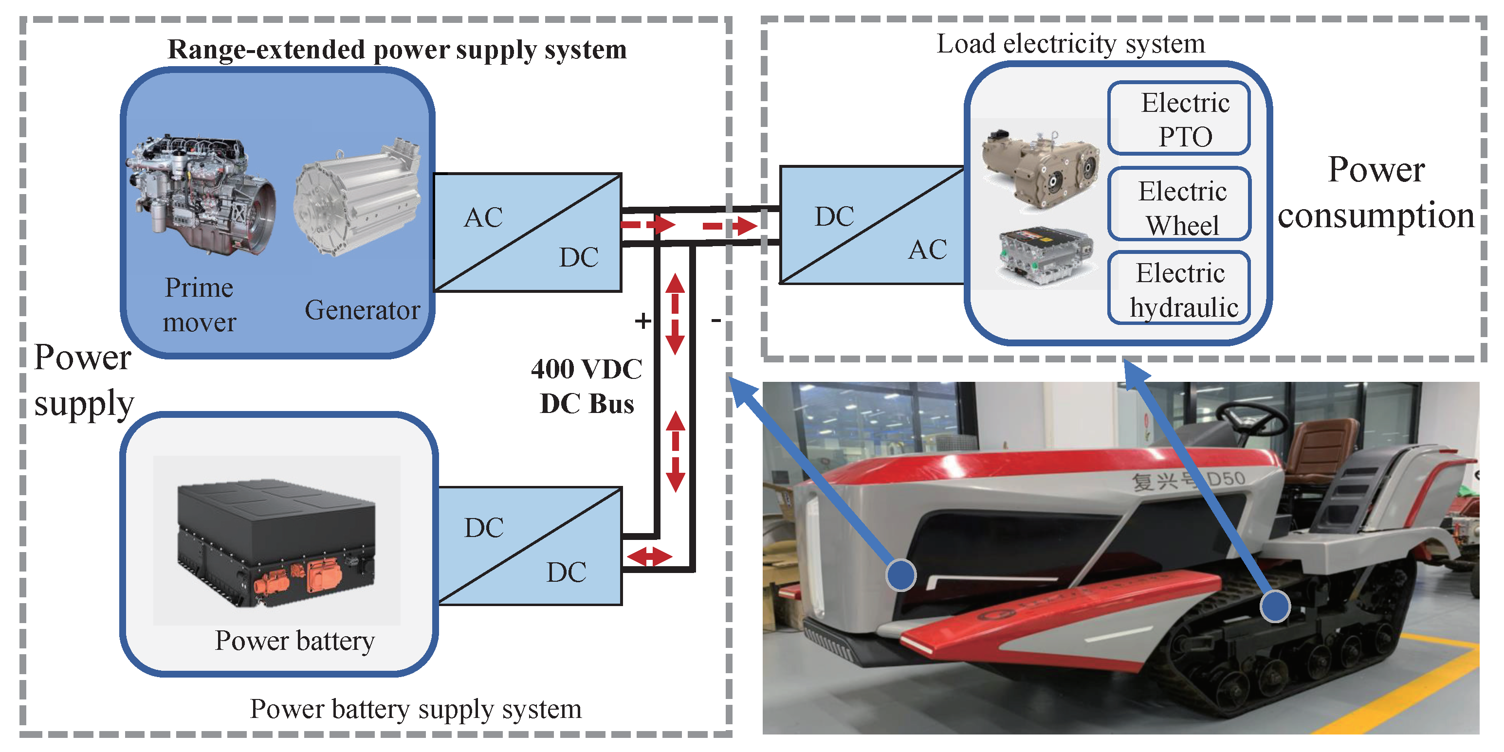
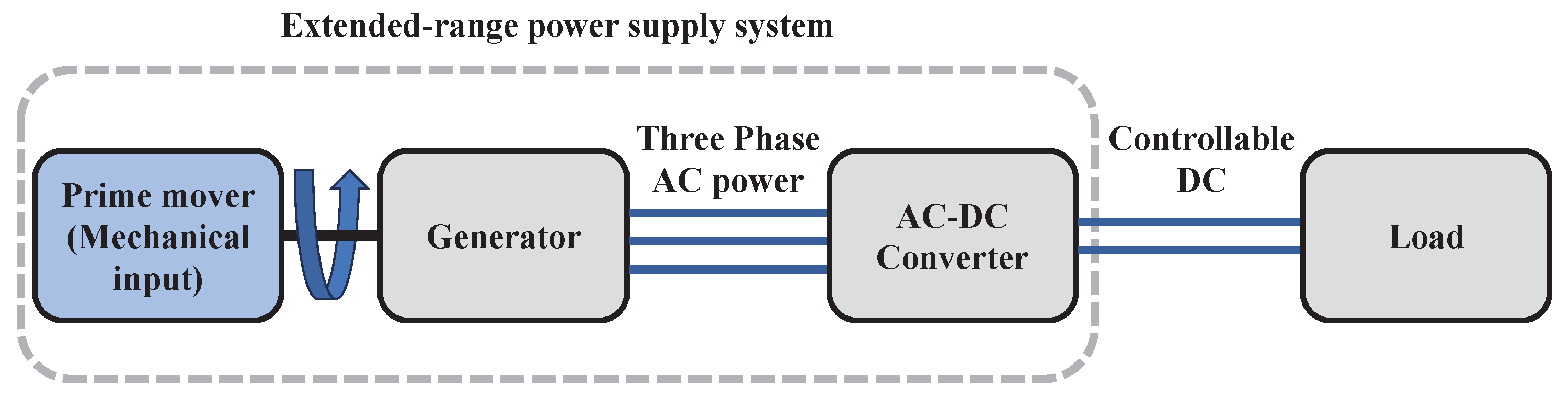
2.1.1. The Power Supply Architecture of the Extended-Range Electric Tractor

The electric drive system of an extended-range electric tractor comprises two primary parts: power supply and power consumption, as illustrated in Figure 1. Power supply encompasses the extended-range power system and the power battery. Power consumption encompasses the drive motor, electric hydraulics, electric PTO, and transmission. Power supply and power consumption are connected via a DC bus.
Unlike a conventional extended-range power supply that works only by injecting current to the DC bus, which is directly connected to the battery, in our study, the extended-range power supply system is designed to maintain a stable DC bus voltage so that it can work alone or in parallel with other extended ranges or batteries, providing more flexibility and possibilities for the power supply structure. The extended-range power supply system comprises two principal components: an AC-DC converter and a DC-DC converter. This manuscript primarily addresses the AC-DC converter aspect.
It comprises the prime mover, the generator, and the AC-DC converter. The prime mover rotates the generator, generating AC voltage. The AC-DC converter is responsible for transforming the AC voltage into a controlled DC voltage with a stable voltage. The control algorithm not only supports current control and voltage regulation but also enables droop control, which is a decrease in output voltage as the power increases. This can facilitate parallel power sharing using multiple power sources, thereby enabling the electric tractor to flexibly extend its overall power and energy capacity.

2.1.2. Hardware Design of the Extended-Range Power Supply System

1.
Hardware architecture
The interconnections of the components of the extended-range power supply system are illustrated in Figure 2. As previously stated, the prime mover is mechanically connected to a three-phase permanent magnet generator. The generator is electrically connected to an AC-DC converter. The output of the AC-DC converter is connected to the DC bus of the electric tractor.
2.
Determination of the DC bus voltage level
It is important to consider the generator size and insulation voltage when determining the DC bus voltage. The generator size is selected using Equations (1) and (2).
D 2 l e f = P n C A
P = 3 E I = T e Ω
where D is the motor armature diameter (m), l e f is the length of the motor armature (m), P is the motor power (W), n is the rotation speed (r/min), C A is a constant, E is the armature phase EMF (V), I is the motor armature current (A), T e is the electromagnetic torque (N·m), and Ω is the mechanical angular velocity (rad/s).
Equations (1) and (2) show that the size of the generator is proportional to the electromagnetic torque T e , and the armature voltage E is proportional to the mechanical angular velocity Ω . Thus, the same power can be produced by increasing the speed; this also lowers the motor torque and decreases the required size and cost of the motor. Therefore, when the power is at a certain level, increasing Ω should reduce the size, loss, and cost of the motor. Increasing Ω also increases E, and the DC bus voltage should be greater than the line peak voltage of the motor. Taking into account the considerations mentioned above as well as the specifications of commercially available motors, a 400 V DC bus voltage platform is chosen for the electric tractor.
3.
Hardware selection
Considering the operational requirements of the extended-range electric tractor, the principle should be satisfied that the battery serves as the main power source and the extended range could be supplied concurrently or separately. In case of continuous heavy load, the battery and range extender could work together. The power should satisfy Equations (3)–(5).
P b a t > P T
P b a t + P R E > P T M A X
P R E = k P b a t
where P b a t is the battery power (W), P R E is the power of the extended-range power supply system (W), P T M A X is the maximum power of the electric tractor (W), and k is the design factor and k < 1.
In this paper, the target power of the electric tractor is 20 kW and the maximum power is 30 kW. Equation (3) should be satisfied in pure electric mode. Equation (4) should be satisfied when the extended-range power supply and the battery work together. As the power battery could provide 20 kW, the required extended-range power supply is designed to be 10 kW. According to the existing equipment, a 10.67 kW prime mover and a 10 kW generator are selected to make required extended-range power supply. The transmission between the engine and the motor is achieved through a B-type belt, with a transmission ratio of approximately 1.33, and the slip rate is maintained at less than 2%. In this system, the center distance is 950 mm, the diameter of the pulley on the engine side is 200 mm, and the diameter of the pulley on the motor side is 149 mm. The final hardware configuration for the extended-range system is shown in Table 2.

2.2. Control Design of the Extended-Range Power Supply System

Three control algorithms are required to ensure the stability and quality of the power supply: current control, voltage control, and droop control. This section elaborates on the design principles of the three control algorithms mentioned above.
Current and voltage control should have good dynamic and steady-state performance. The current control is in milliseconds and the voltage control is in seconds to avoid large voltage drops. In addition, the droop control should achieve a proportional downward adjustment of the bus voltage as the output power increases.

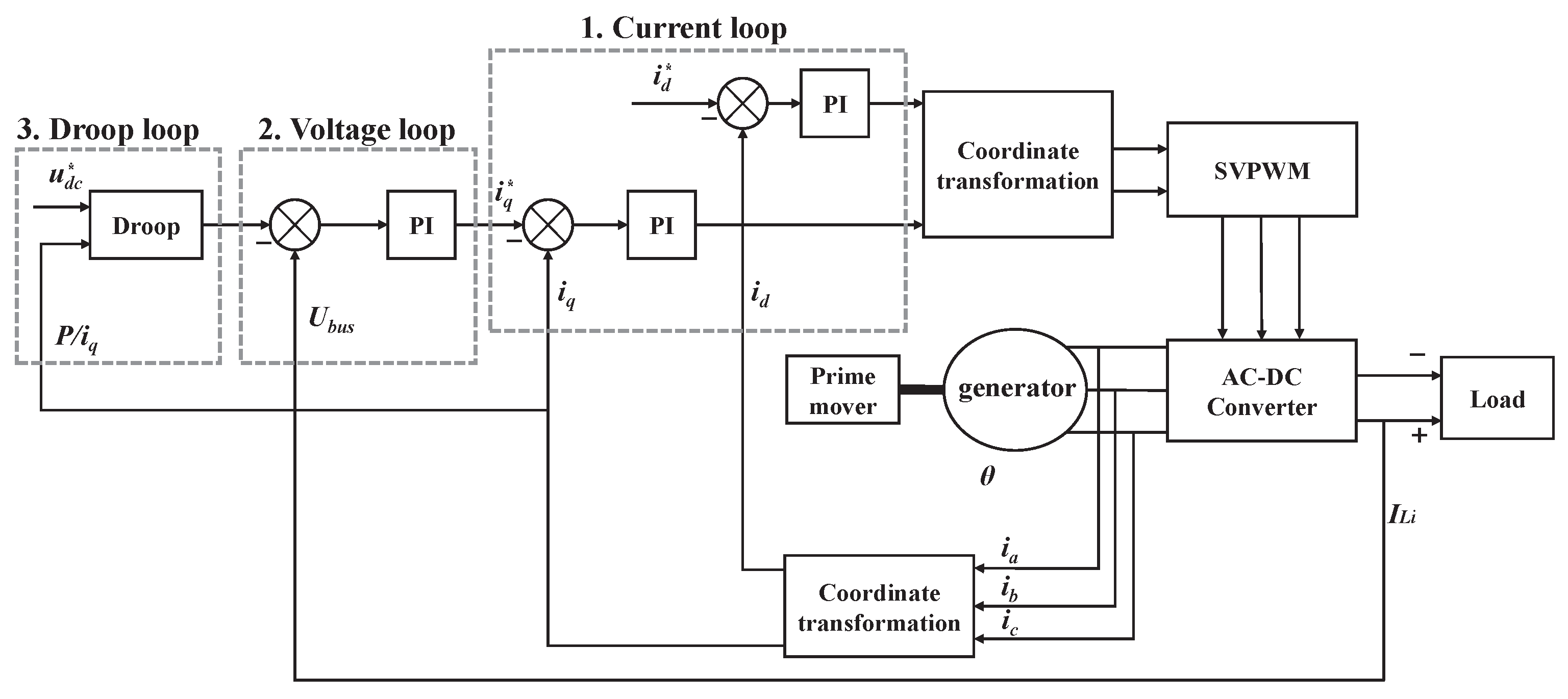
2.2.1. General Overview of the Control Strategy of the Extended-Range Power Supply System

The control structure of the extended-range system is shown in Figure 3. The prime mover rotates the generator to produce an uncontrolled AC voltage, which is then converted to a controlled DC voltage, using a FOC drive strategy with current control, voltage control, and droop control.
Details of the parameter variables involved in Figure 3 are shown in Table 3.
The current control first transforms three-phase generator stator currents i a , i b , and i c into i d and i q in the d-q coordinate system by coordinate transformation. Then, the difference between i d and i q and i d * and i q * is used as the error input to the current loop PI regulator to adjust the motor terminal voltage so that the current can be controlled to follow the given current reference. The voltage controller regulates the DC bus voltage by adjusting the q-axis current i q through the voltage loop PI regulator. Droop control provides a downward adjustment of the DC bus reference voltage u d c * as output power increases, facilitating power sharing between multiple power supplies.

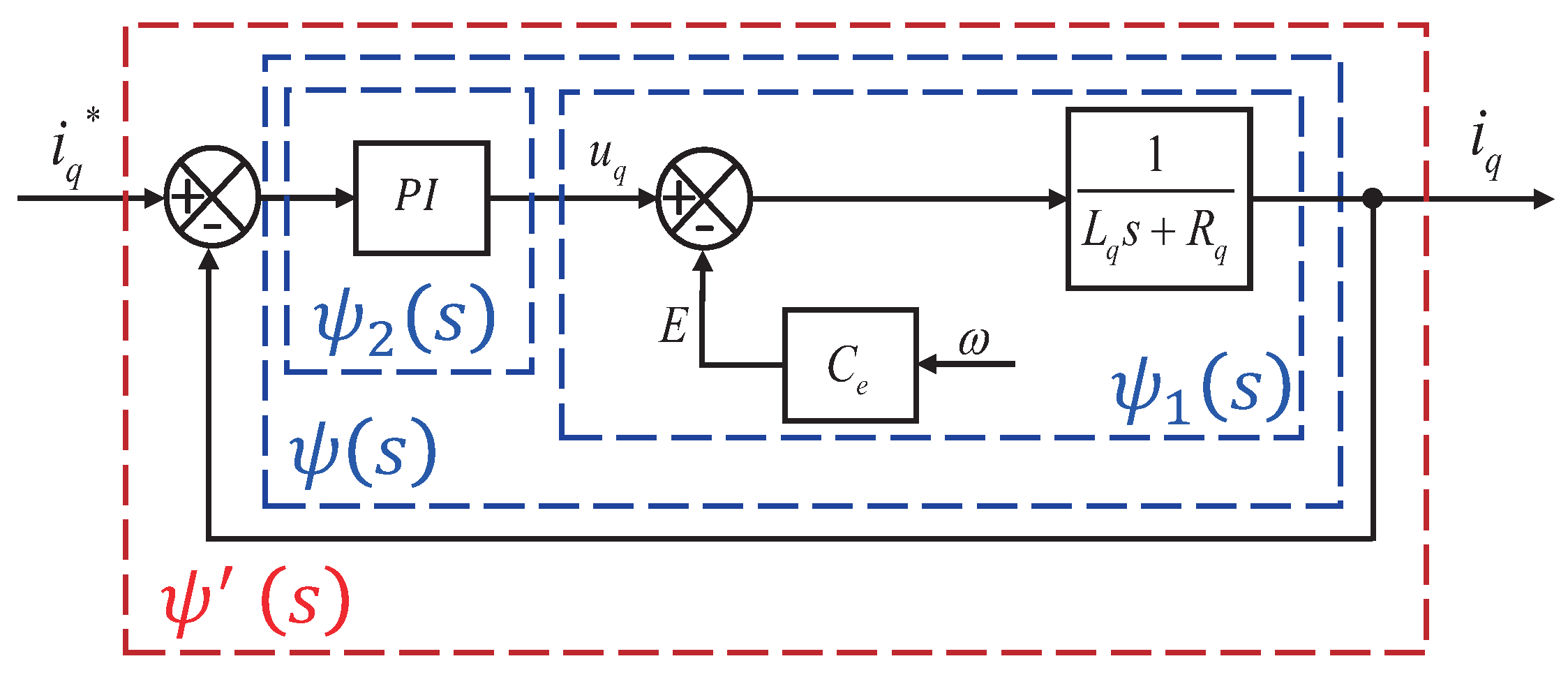
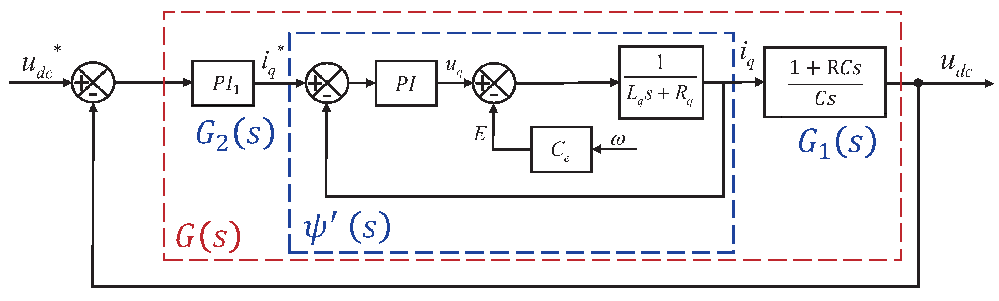
2.2.2. Mathematical Model of the Controlled Object of Extended-Range Power Supply System

The mathematical model of the generator model is necessary to develop a control strategy for the extended-range power supply system. The generator used is a PMSM, and its model is given by Equation (6).
U d = R s i d + L d d i d d t p ω i q L q U q = R s i q + L q d i q d t + p ω i d L d + λ p ω T e = 3 2 p [ λ i q + ( L d L q ) i d i q ]
where U d is the d-axis voltage (V), L d is the d-axis inductance (H), U q is the q-axis voltage (V), L q is the q-axis inductance (H), p is the number of pole pairs of the motor; λ is the magnetic flux (Wb), ω is the rotor angular speed (rad/s), and R s is the stator resistance ( Ω ).
As mentioned above, the motor is driven by the FOC algorithm with i d * = 0, and the model in Equation (6) can be simplified as in Equation (7), which makes the PMSM quite similar to a DC motor. The details of the parameters for the mathematical model variables of PMSM and DC motors are shown in Table 3.
U d = R q i q + L q d i q d t + C e ω T e = 3 2 C e i q
where C e is the Back EMF coefficient, and R q is the armature resistance ( Ω ).

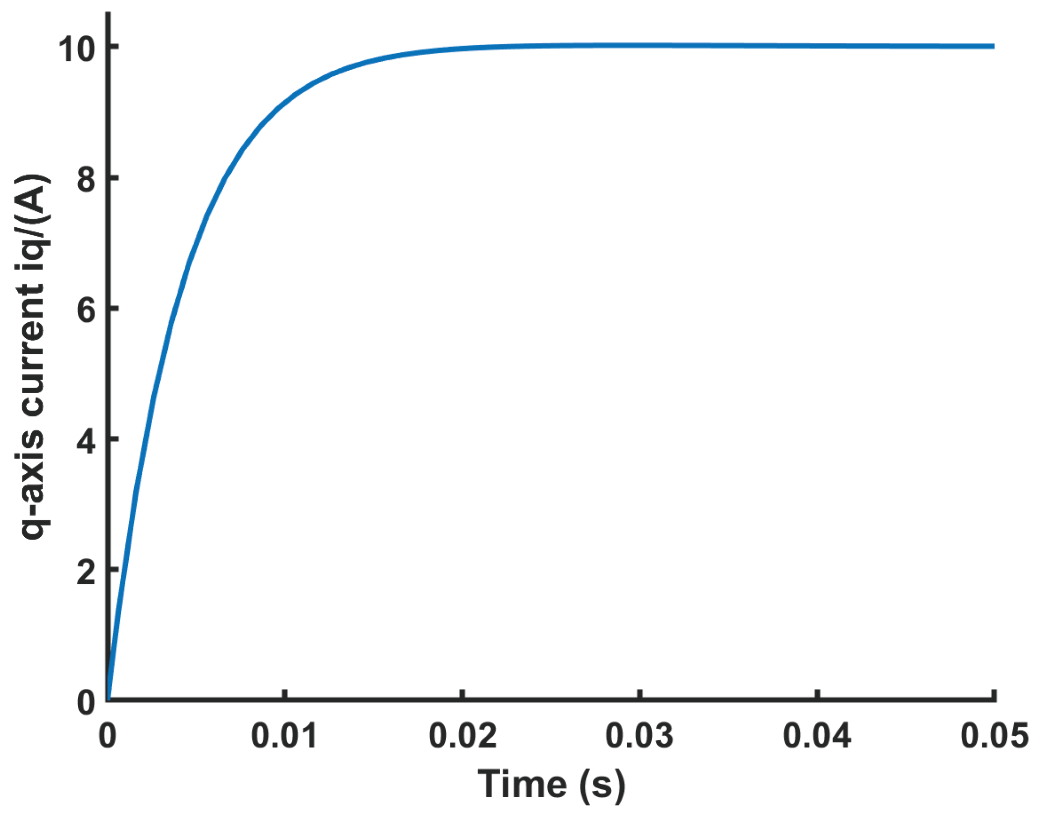
2.2.3. Design of Current Control for Extended-Range Power Supply System

Based on the plant in Equation (7), the current loop PI control block diagram is shown in Figure 4.
The transfer function of the plant for current control is noted as ψ 1 ( s ) , and the transfer function of the PI controller is noted as ψ 2 ( s ) , as given in Equations (8) and (9).
ψ 1 ( s ) = 1 L q s + R q
ψ 2 ( s ) = K p i ( 1 + T i i s ) T i i s
where K p i is the proportional gain of the current controller, and T i i is the integration time constant of the current controller.
Therefore, the open-loop transfer function ψ ( s ) for current control can be represented by Equation (10).
ψ ( s ) = ψ 1 ( s ) · ψ 2 ( s ) = 1 L q s + R q · K p i ( 1 + T i i s ) T i i s
According to ψ ( s ) , the open-loop Bode diagram can be plotted with different PI parameters, as shown in Figure 5.
In classical control theory, a larger area enclosed by the amplitude–frequency characteristic curve above the 0 dB horizontal axis corresponds to a faster closed-loop response. Furthermore, a larger phase margin corresponds to a smaller closed-loop overshoot. When comparing the different parameters, it becomes evident that curve (a) not only ensures a sufficient enclosed area but also exhibits an adequate phase margin and high-frequency suppression capability. In contrast, curve (b) displays a small enclosed area, signifying a slower response. Meanwhile, curve (c) features a large enclosed area but lacks sufficient high-frequency attenuation capability with larger gain, rendering the closed-loop system susceptible to the influence of re-measurement noise and the discrete control effect curve. Consequently, the parameters K p i = 0.2, T i i = 0.015 from curve (a) are ultimately adopted.
The closed-loop transfer function ψ ( s ) is given by Equation (11).
ψ ( s ) = ψ ( s ) 1 + ψ ( s ) = K p i ( 1 + T i i s ) T i i s ( L q s + R q ) + K p i ( 1 + T i i s )
The closed-loop simulation is also performed, and the obtained closed-loop current control performance is shown in Figure 6. The settling time is approximately 20 ms for a given 10 A, which meets the current control requirements of fast response.

2.2.4. Design of Voltage Control for Extended-Range Power Supply System

For voltage control, the system includes the tuned current loop, the DC bus capacitor, and the load. As the speed of the extended-range system is essentially constant during steady-state operation and the speed variation during dynamic adjustment was small, the influence of the rotational inertia and friction of the mechanical rotating parts can be ignored for the dynamic analysis. The voltage control block diagram can therefore be obtained as shown in Figure 7.
The DC bus transfer function G 1 ( s ) includes the capacitance C and the load R and is given by Equation (12).
G 1 ( s ) = 1 + R C s C s
where C is the voltage regulator capacitor (F), and R is the load resistance ( Ω ).
The voltage controller is noted as G 2 ( s ) , given by Equation (13).
G 2 ( s ) = K p u ( 1 + T i u s ) T i u s
where K p u is the proportional gain of the voltage controller, and T i u is the integral time constant of the voltage control.
The open-loop transfer function G ( s ) for voltage control by is given by Equation (14).
G ( s ) = G 1 ( s ) · ψ ( s ) · G 2 ( s )
Similarly, the closed-loop control performance with different control parameters is evaluated with the open-loop Bode diagram curve, as shown in Figure 8. The final selected control parameters are K p u = 0.01, T i u = 1.
Then, the closed-loop performance was verified. G ( s ) was the closed-loop transfer function of the voltage loop, given by Equation (15).
G ( s ) = G ( s ) 1 + G ( s )
The closed-loop performance was evaluated by closed-loop simulation, as shown in Figure 9. It can be seen that the DC bus voltage can be controlled at 400 V. The voltage dropped by 48 V when the 10 kW load was suddenly added for 10 s. After a response time of 3.5 s, the regulated voltage of 400 V was recovered, and the overshoot of the recovery process was less than 1%. The dynamic response of the system was fast and smooth, with no steady-state errors, meeting the requirements of voltage control.

2.2.5. Design of Droop Control Parameters for Extended-Range Power Supply System

Droop control provides a downward adjustment of the DC bus voltage reference u d c * as output power increases, but droop control enables load sharing between multiple power sources without communication. For example, in the case of a tractor equipped with a harvesting system, there is a sudden increase in output power the moment the harvesting system begins to operate. In this case, the droop control can automatically adjust the power distribution without communication by using the engine to share this increased load, thus enabling load sharing between the battery pack and the engine. The voltage droop control characteristic is shown in Figure 10. Principally, the droop control had a linear droop characteristic and the relationship between the DC bus voltage and current satisfied Equation (16).
U b u s = u d c * r d i I L i
where r d i is the slope of the droop control.
For droop control, the smaller the droop slope factor, the less variation in the bus voltage, but the more difficult it is to share power between multiple sources. On the other hand, a large droop slope factor could reduce the efficient utilization of the DC bus voltage. In this application, the generation class is 10 kW, the maximum permissible bus voltage variation is 20 V at rated generator power, the maximum DC bus current is 26 A, and finally, the parameters are selected as r d i = 0.77 according to Equation (16).

3. Results and Discussion

This section provides the experimental verification of the designed extended-range power supply system. The control performance of the current loop, voltage loop, and droop control are tested for steady-state and dynamic performance, and the start-up process is also optimized.

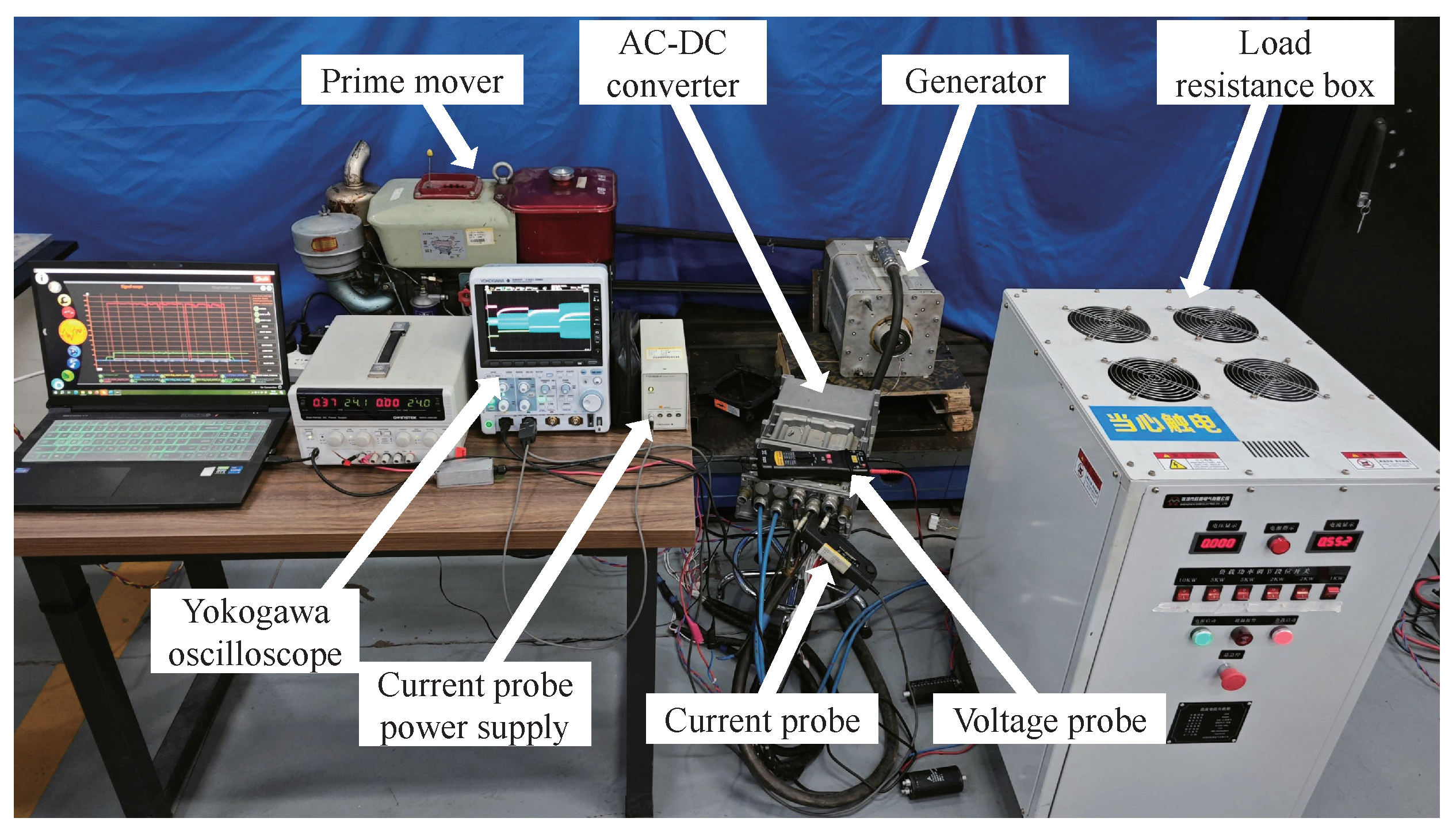
3.1. Experimental and Test Conditions

The extended-range power supply system experiment bench is shown in Figure 11. The extended-range power supply system experiment bench consists of a prime mover, a generator, an AC-DC converter, and a load. The load is simulated by a variable resistor.
The load can be switched to different configurations under the tested voltage, corresponding to 1 kW, 2 kW, 5 kW, 10 kW power consumption, marked as Loads 1∼4, respectively, and the resistance values are shown in Table 4.
Experimental data are collected with a DLM3034 oscilloscope, the manufacturer of the equipment is Yokogawa Test & Measurement Corporation, located in Tokyo, Japan. High-bandwidth probes are used to measure the bus voltage and the three-phase stator current of the generator.

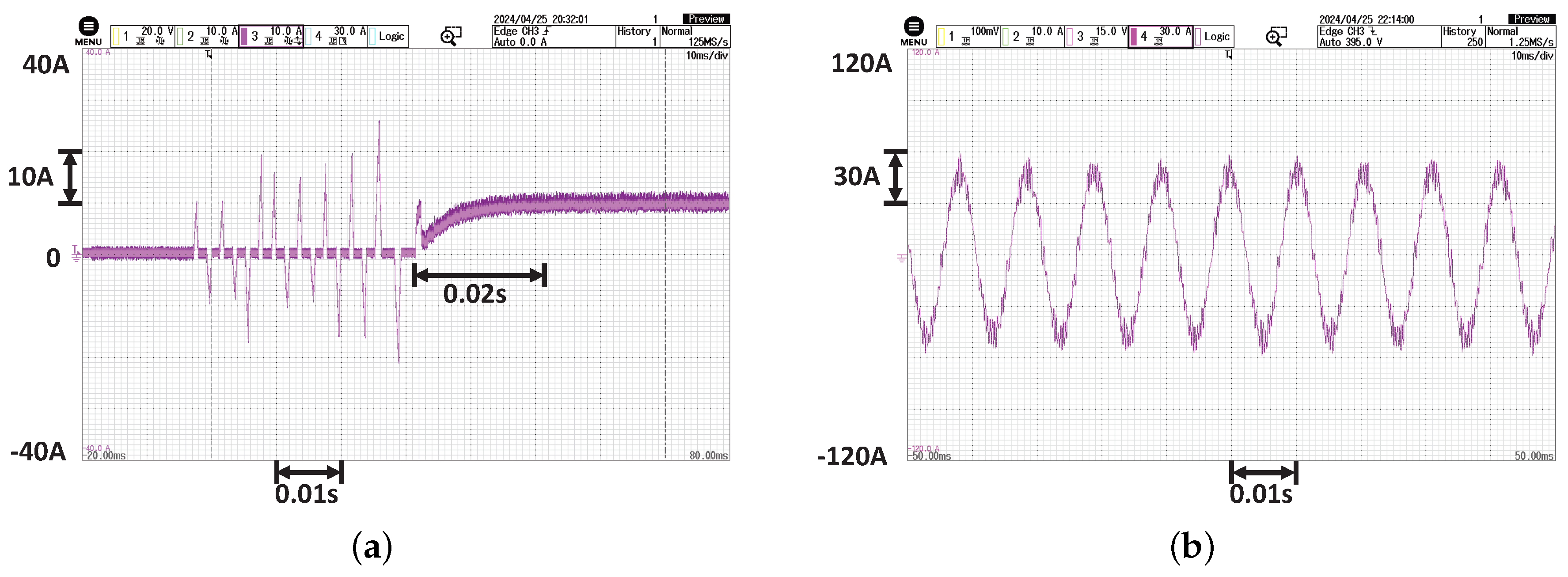
3.2. Current Loop Control Characteristics Experiment

The dynamic and steady-state current control performance is verified. To avoid the influence of rotation, the dynamic performance is evaluated by locking the shaft and injecting current into the generator.
The current dynamic response obtained is shown in Figure 12a. Ignoring the initial transient current burr due to the start-up injection for estimating the generator position, it can be seen that for a given desired current of i q * = 10 A, the settling time is within 20 ms, which is consistent with the control design and simulation results. The steady-state control performance is shown in Figure 12b. The generator phase current waveform is stable and sinusoidal, indicating good steady-state control performance.

3.3. Start-Up Ramping

In the case of an extended-range power supply, there is a contradiction in the nature of the control parameters: the control parameter cannot be adjusted either too fast or too slow. If the control parameter is too fast, it could cause an impact force on the prime mover during a sudden change condition, especially during the start-up, which may lead to the prime mover shutting down. If the control response is too slow, the DC bus voltage drop may be overly large in the condition of disturbance.
To handle this contradiction, this paper implements fast control parameters with a start-up ramp, and the ramp rate is set to 100 V/s. The start-up process is tested at different speeds of 1400 r/min, 1800 r/min, 2200 r/min, and 2600 r/min, respectively, and the resulting bus voltage waveform is shown in Figure 13.
With the start-up algorithm, the DC bus voltage could be smoothly ramped up from the unregulated voltage to the desired voltage at the desired ramp rate. The initial unregulated voltage comes from the inverter diode before the inverter chopping starts. The results show that the system can start at different speeds within 2∼3 s to achieve 400 V voltage stabilization, and the starting process is smooth and could avoid excessive impact to cause the prime mover shutdown.

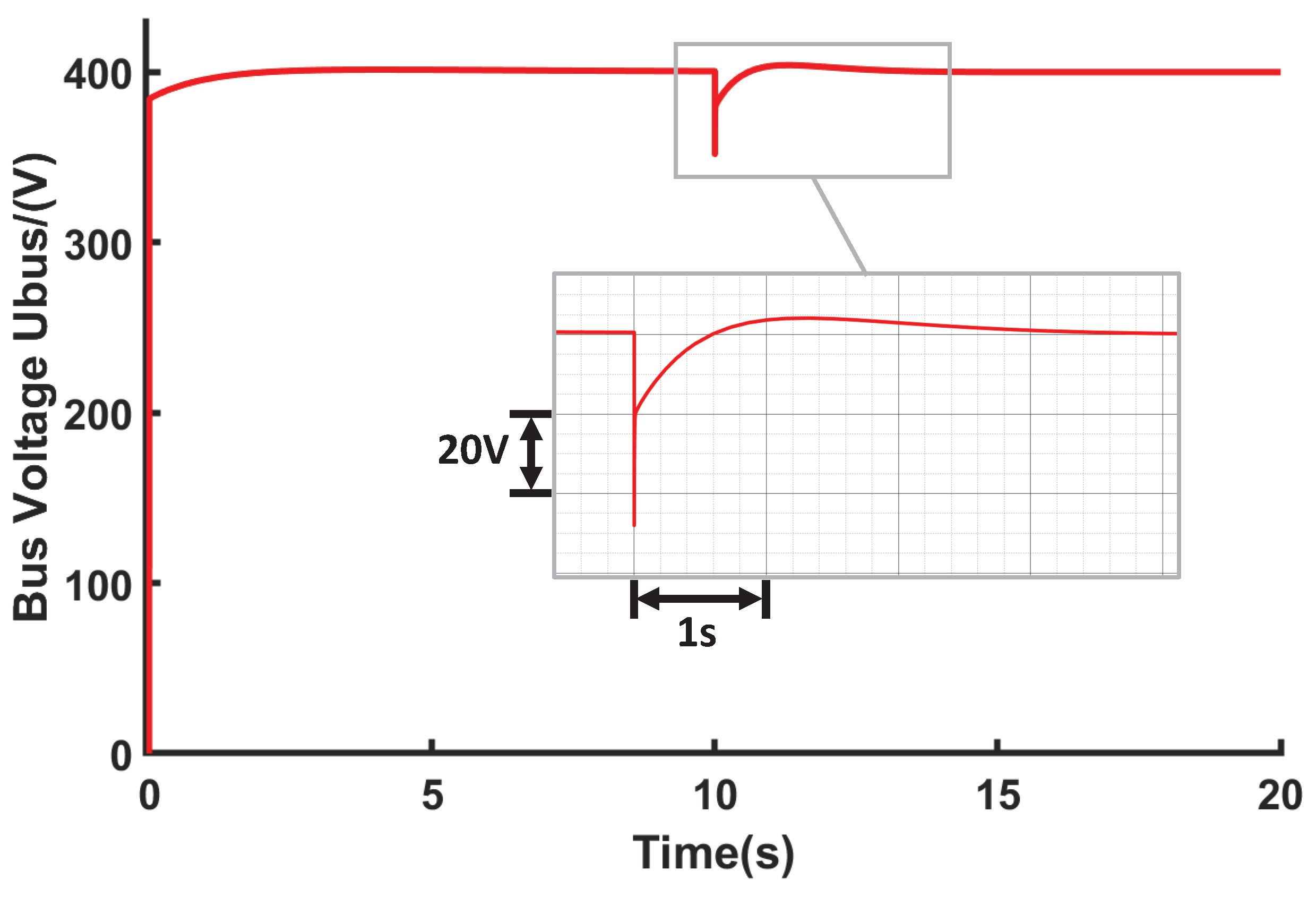
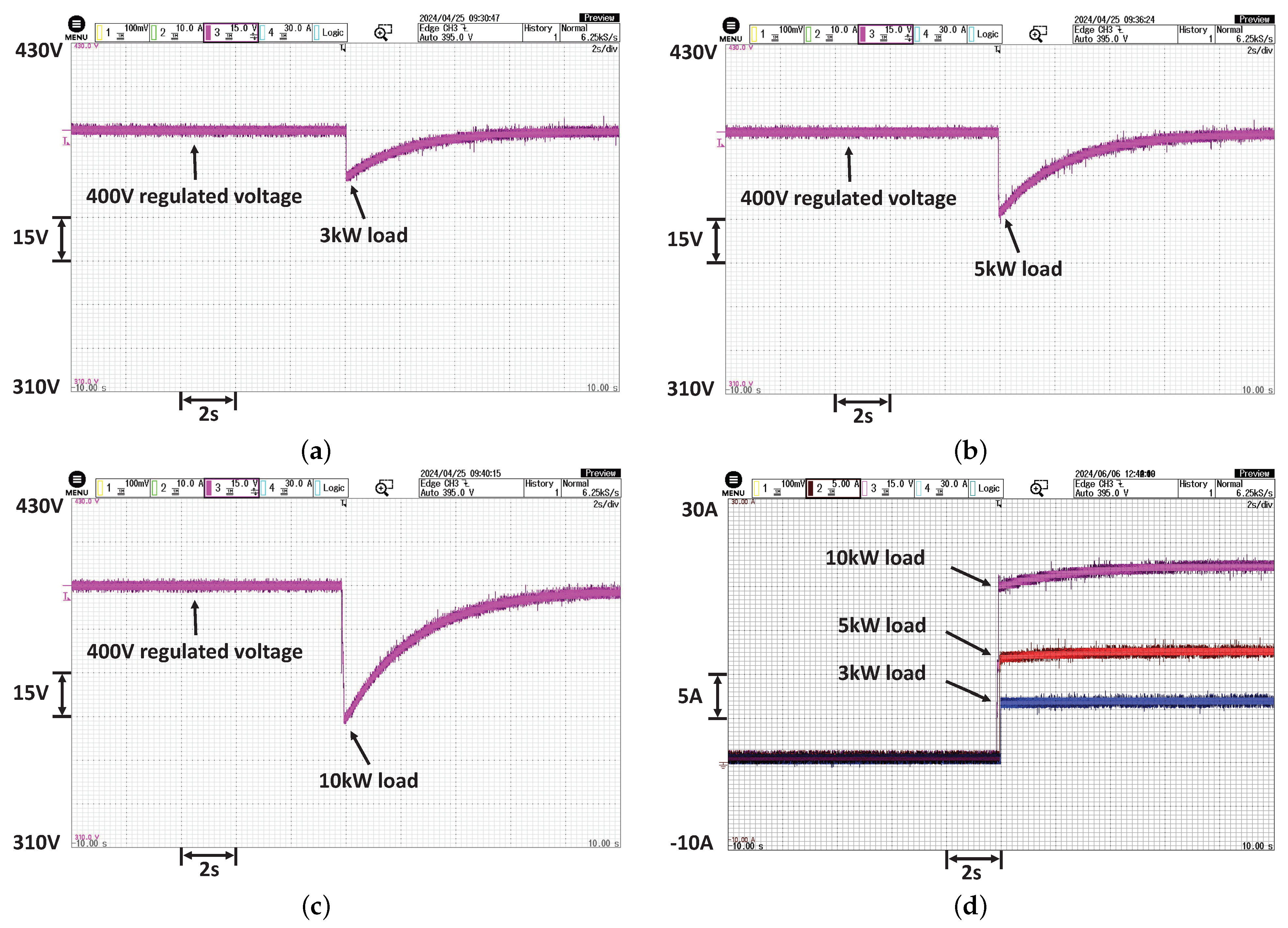
3.4. Voltage Loop Dynamic Control Characteristics Experiment

The voltage control performance is evaluated experimentally, mainly focusing on the dynamic performance, because the voltage control PI controller is able to ensure no steady-state error for voltage control.
The test is performed as follows. First, the control is raised to the steady state with stabilized voltage, then the load resistor is suddenly connected to the DC bus. The results of the DC bus voltage fluctuation and current waveforms are shown in Figure 14.
Figure 14a–c show the results after the sudden introduction of 3 kW, 5 kW, and 10 kW loads, representing 30%, 50%, and 100% load conditions, respectively. The DC bus voltage experiences reductions of 16 V, 28 V, and 46 V, respectively. It is noteworthy that the maximum voltage drop remains within 12% of the rated voltage even under the 100% sudden load condition.
The maximum voltage recovery time under disturbance is less than 9 s. The results show that the designed extended-range power supply system can ensure stable power supply to the load even in the case of 100% sudden load change.
The DC bus current I L i is shown in Figure 14d. The DC bus currents step up to 7.48 A, 12.83 A, and 22.58 A for different loads, respectively. There are no drastic fluctuations and overshoots in the load current. The transient process of voltage dip aligns with the current rise process following sudden load changes. Furthermore, the load current exhibits smooth behavior, demonstrating that the voltage control performance of the extended-range power supply system meets the design requirements.

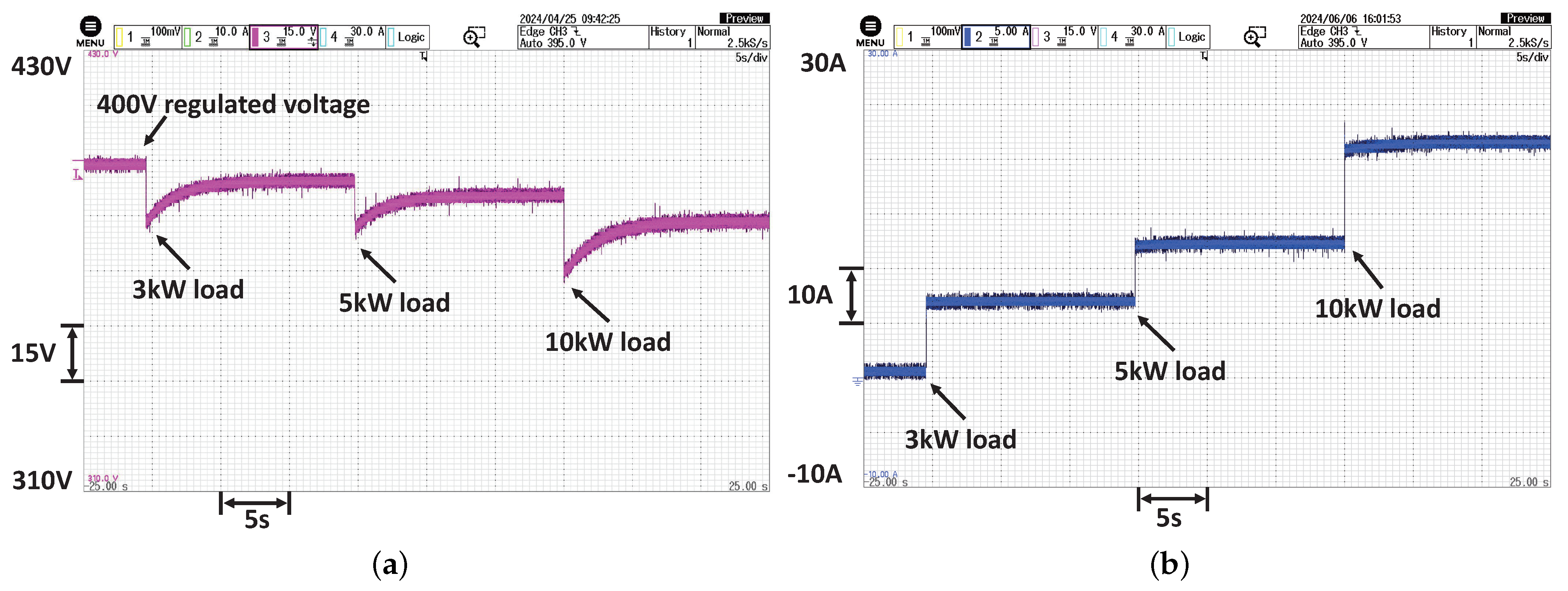
3.5. Droop Control Steady State Characteristics Experiment

Droop control facilitates the downward adjustment of the DC bus voltage as output power increases, enabling power sharing among multiple sources without the need for intercommunication. The functionality of the droop control is validated and tested at various load levels (0 kW, 3 kW, 5 kW, and 10 kW), with the r d i value set to 0.75. The resulting DC bus voltage and current waveforms are illustrated in Figure 15.
The DC bus voltage is shown in Figure 15a. The DC bus voltage is initially stable at 400 V. Then, when a 3 kW load is switched on, the droop control eventually drops the voltage to 394.5 V, with a maximum 3% transient undershoot to 383.2 V. For 5 kW and 10 kW loads, the corresponding final droop voltages are 390.8 V and 383.2 V, respectively, with maximum 2.6% and 3.5% transient undershoot to 380.5 V and 369.8 V.
In all cases, the voltage transient undershoot could be recovered within 7 s. The DC bus current I L i is shown in Figure 15b. The currents are 7.33 A, 12.67 A, and 22.37 A for different loads. The calculated r d i values of the three different loads are 0.73, 0.75, and 0.74, respectively. The results are consistent with the control design and could meet the requirements.

4. Conclusions

In this paper, an extended-range power supply system has been designed with the aim of continuously powering our independently developed electric tractor. The hardware configuration and control design have been completed and experimentally tested for dynamic and steady-state operation.
The detailed design method and design process for the extended-range power supply system were given, including current control, voltage control, and droop control. Experimental results showed that the actual performance is in accordance with the design requirement and simulation results. There is no steady state error for the DC bus voltage. In the transient test with sudden load change, the maximum DC bus voltage drop is less than 12%. The voltage droop recovers to within a 3% range in less than 4 s and the recovery time is less than 9 s. The droop control works well with the design parameters, facilitating future power sharing between multiple sources without communication. The start-up process was also optimized with a ramp to avoid shutting down the prime mover. The designed system meets the requirements for continuous power supply of an electric tractor.

Author Contributions

Conceptualization, B.W. and Y.L.; methodology, B.W.; software, Y.L. and X.C.; validation, X.C. and Y.L.; formal analysis, Y.L.; investigation, B.W., X.C. and Y.L.; resources, B.W.; data curation, Y.L. and D.W.; writing—original draft preparation, Y.L.; writing—review and editing, B.W.; visualization, Y.L. and S.S.; supervision, D.W. and S.S.; project administration, B.W.; funding acquisition, B.W. All authors have read and agreed to the published version of the manuscript.

Funding

This paper was supported by the Collaborative Innovation Center for Shangdong’s Main crop Production Equipment and Mechanization under Grant SDXTZX-22, Shandong Provincial Natural Science Foundation under Grant ZR2021ME018, National Key Research and Development Program of China under Grant 2022YFE0125800 and Lu-Yu Collaborative Project under Grant 2021LYXZ013.

Institutional Review Board Statement

Not applicable.

Data Availability Statement

The data will be made available upon reasonable request from the corresponding authors.

Acknowledgments

The authors would like to thank all those who contributed to this study.

Conflicts of Interest

Author Xianggang Chu is now employed by the company Weichai Lovol Intelligent Agricultural Technology Co., Ltd., after graduation from Qingdao Agricultural University. The remaining authors declare that the research was conducted in the absence of any commercial or financial relationships that could be construed as a potential conflict of interest.

Abbreviations

The following abbreviations are used in this manuscript:
ACAlternative Current
DCDirect Current
CCSCombined Charging System
SOCState of Charge
PTOPower Take-Off
AC-DCAlternative Current–Direct Current
EMFElectromotive Force
FOCField Orientation Control
PMSMPermanent Magnet Synchronous Motor
PIProportional Integral

References

  1. Khatawkar, D.S.; James, P.S.; Dhalin, D. Modern trends in farm machinery-electric drives: A review. Int. J. Curr. Microbiol. Appl. Sci. 2019, 8, 83–98. [Google Scholar] [CrossRef]
  2. Mileusnić, Z.; Petrović, D.; Đević, M. Comparison of tillage systems according to fuel consumption. Energy 2010, 35, 221–228. [Google Scholar] [CrossRef]
  3. Janulevičius, A.; Juostas, A.; Pupinis, G. Tractor’s engine performance and emission characteristics in the process of ploughing. Energy Convers. Manag. 2013, 75, 498–508. [Google Scholar] [CrossRef]
  4. Katrašnik, T. Hybridization of powertrain and downsizing of IC engine–A way to reduce fuel consumption and pollutant emissions–Part 1. Energy Convers. Manag. 2007, 48, 1411–1423. [Google Scholar] [CrossRef]
  5. Moreda, G.; Muñoz-García, M.; Barreiro, P. High voltage electrification of tractor and agricultural machinery–A review. Energy Convers. Manag. 2016, 115, 117–131. [Google Scholar] [CrossRef]
  6. Moghadasi, S.; Long, Y.; Jiang, L.; Munshi, S.; McTaggart-Cowan, G.; Shahbakhti, M. Design and performance analysis of hybrid electric class 8 heavy-duty regional-haul trucks with a micro-pilot natural gas engine in real-world highway driving conditions. Energy Convers. Manag. 2024, 309, 118451. [Google Scholar] [CrossRef]
  7. Deng, X.; Sun, H.; Lu, Z.; Cheng, Z.; An, Y.; Chen, H. Research on dynamic analysis and experimental study of the distributed drive electric tractor. Agriculture 2022, 13, 40. [Google Scholar] [CrossRef]
  8. An, Y.; Wang, L.; Deng, X.; Chen, H.; Lu, Z.; Wang, T. Research on Differential Steering Dynamics Control of Four-Wheel Independent Drive Electric Tractor. Agriculture 2023, 13, 1758. [Google Scholar] [CrossRef]
  9. Mao, Y.; Wu, Y.; Yan, X.; Liu, M.; Xu, L. Simulation and experimental research of electric tractor drive system based on Modelica. PLoS ONE 2022, 17, e0276231. [Google Scholar] [CrossRef]
  10. Zhang, X.; Tan, S.C.; Li, G.; Li, J.; Feng, Z. Components sizing of hybrid energy systems via the optimization of power dispatch simulations. Energy 2013, 52, 165–172. [Google Scholar] [CrossRef]
  11. Wu, Z.; Wang, J.; Xing, Y.; Li, S.; Yi, J.; Zhao, C. Energy Management of Sowing Unit for Extended-Range Electric Tractor Based on Improved CD-CS Fuzzy Rules. Agriculture 2023, 13, 1303. [Google Scholar] [CrossRef]
  12. Faria, R.; Moura, P.; Delgado, J.; De Almeida, A.T. A sustainability assessment of electric vehicles as a personal mobility system. Energy Convers. Manag. 2012, 61, 19–30. [Google Scholar] [CrossRef]
  13. Mousazadeh, H.; Keyhani, A.; Javadi, A.; Mobli, H.; Abrinia, K.; Sharifi, A. Life-cycle assessment of a Solar Assist Plug-in Hybrid electric Tractor (SAPHT) in comparison with a conventional tractor. Energy Convers. Manag. 2011, 52, 1700–1710. [Google Scholar]
  14. Li, J.; Wu, X.; Zhang, X.; Song, Z.; Li, W. Design of distributed hybrid electric tractor based on axiomatic design and Extenics. Adv. Eng. Inform. 2022, 54, 101765. [Google Scholar] [CrossRef]
  15. Liu, M.; Lei, S.; Zhao, J.; Meng, Z.; Zhao, C.; Xu, L. Review of development process and research status of electric tractors. Trans. Chin. Soc. Agric. Mach 2022, 53, 348–364. [Google Scholar]
  16. Flórez-Orrego, D.; Silva, J.A.; de Oliveira Jr, S. Exergy and environmental comparison of the end use of vehicle fuels: The Brazilian case. Energy Convers. Manag. 2015, 100, 220–231. [Google Scholar] [CrossRef]
  17. Pali, H.S.; Kumar, N.; Alhassan, Y. Performance and emission characteristics of an agricultural diesel engine fueled with blends of Sal methyl esters and diesel. Energy Convers. Manag. 2015, 90, 146–153. [Google Scholar] [CrossRef]
  18. Liu, M.; Li, Y.; Xu, L.; Wang, Y.; Zhao, J. General modeling and energy management optimization for the fuel cell electric tractor with mechanical shunt type. Comput. Electron. Agric. 2023, 213, 108178. [Google Scholar] [CrossRef]
  19. Li, X.; Xu, L.; Liu, M.; Yan, X.; Zhang, M. Research on torque cooperative control of distributed drive system for fuel cell electric tractor. Comput. Electron. Agric. 2024, 219, 108811. [Google Scholar] [CrossRef]
  20. Yang, H.; Sun, Y.; Xia, C.; Zhang, H. Research on energy management strategy of fuel cell electric tractor based on multi-algorithm fusion and optimization. Energies 2022, 15, 6389. [Google Scholar] [CrossRef]
  21. Chen, L.; Zhan, Q.; Wang, W.; Huang, X.; Zheng, Q. Design and experiment of electric drive system for pure electric tractor. Trans. Chin. Soc. Agric. Mach. 2018, 49, 388–394. [Google Scholar]
  22. Wang, B.; Sechilariu, M.; Locment, F. Intelligent DC microgrid with smart grid communications: Control strategy consideration and design. IEEE Trans. Smart Grid 2012, 3, 2148–2156. [Google Scholar] [CrossRef]
  23. Wang, B.; Qiao, M.; Chu, X.; Shang, S.; Wang, D. Design and Experimental Study of Extended-Range Electric Caterpillar Tractor. Trans. Chin. Soc. Agric. Mach 2023, 54, 431–439. [Google Scholar]
  24. Dong, Z.; Qin, J.; Hao, T.; Li, X.; Chi, K.T.; Lu, P. Distributed cooperative control of DC microgrid cluster with multiple voltage levels. Int. J. Electr. Power Energy Syst. 2024, 159, 109996. [Google Scholar] [CrossRef]
  25. Xiong, W.; Zhang, Y.; Yin, C. Optimal energy management for a series–parallel hybrid electric bus. Energy Convers. Manag. 2009, 50, 1730–1738. [Google Scholar] [CrossRef]
  26. Marzougui, H.; Kadri, A.; Martin, J.P.; Amari, M.; Pierfederici, S.; Bacha, F. Implementation of energy management strategy of hybrid power source for electrical vehicle. Energy Convers. Manag. 2019, 195, 830–843. [Google Scholar] [CrossRef]
  27. Liu, J.; Xia, C.; Jiang, D.; Sun, Y. Development and testing of the power transmission system of a crawler electric tractor for greenhouses. Appl. Eng. Agric. 2020, 36, 797–805. [Google Scholar] [CrossRef]
  28. Li, M.; Xu, H.; Li, W.; Liu, Y.; Li, F.; Hu, Y.; Liu, L. The structure and control method of hybrid power source for electric vehicle. Energy 2016, 112, 1273–1285. [Google Scholar] [CrossRef]
  29. Yu, Y.; Hao, S.; Guo, S.; Tang, Z.; Chen, S. Motor Torque Distribution Strategy for Different Tillage Modes of Agricultural Electric Tractors. Agriculture 2022, 12, 1373. [Google Scholar] [CrossRef]
  30. Alegria, E.; Brown, T.; Minear, E.; Lasseter, R.H. CERTS microgrid demonstration with large-scale energy storage and renewable generation. IEEE Trans. Smart Grid 2013, 5, 937–943. [Google Scholar] [CrossRef]
  31. Justo, J.J.; Mwasilu, F.; Lee, J.; Jung, J.W. AC-microgrids versus DC-microgrids with distributed energy resources: A review. Renew. Sustain. Energy Rev. 2013, 24, 387–405. [Google Scholar] [CrossRef]
  32. Hou, X.; Zhang, X.; Huang, S.; Xu, P.; Shen, J. Measurement of engine performance and maps-based emission prediction of agricultural tractors under actual operating conditions. Measurement 2023, 222, 113637. [Google Scholar] [CrossRef]
  33. Ren, G.; Wang, J.; Chen, C.; Wang, H. A variable-voltage ultra-capacitor/battery hybrid power source for extended range electric vehicle. Energy 2021, 231, 120837. [Google Scholar] [CrossRef]
  34. Cao, X.; Han, M.; Nee, H.P.; Yan, W. A new method for simplifying complex DC systems and obtaining the controller droop coefficients. IEEE Trans. Power Syst. 2021, 37, 996–1006. [Google Scholar] [CrossRef]
  35. Ahmed, K.; Hussain, I.; Seyedmahmoudian, M.; Stojcevski, A.; Mekhilef, S. Voltage stability and power sharing control of distributed generation units in DC microgrids. Energies 2023, 16, 7038. [Google Scholar] [CrossRef]
  36. Lee, H.S.; Kim, J.S.; Park, Y.I.; Cha, S.W. Rule-based power distribution in the power train of a parallel hybrid tractor for fuel savings. Int. J. Precis. Eng. Manuf.-Green Technol. 2016, 3, 231–237. [Google Scholar] [CrossRef]
Figure 1. Power block diagram of the extended-range electric tractor system.
Agriculture 14 01551 g001
Figure 2. Power block diagram of the extended-range electric tractor system.
Agriculture 14 01551 g002
Figure 3. Block diagram of an extended-range power supply system.
Agriculture 14 01551 g003
Figure 4. Current control equivalent structure diagram.
Agriculture 14 01551 g004
Figure 5. Open-loop Bode diagram of current loop.
Agriculture 14 01551 g005
Figure 6. Response characteristics simulated curve of i q .
Agriculture 14 01551 g006
Figure 7. Equivalent structure diagram of voltage loop.
Agriculture 14 01551 g007
Figure 8. Equivalent structure diagram of voltage loop.
Agriculture 14 01551 g008
Figure 9. Simulation results of voltage control.
Agriculture 14 01551 g009
Figure 10. Characteristic curve of voltage droop control.
Agriculture 14 01551 g010
Figure 11. Extended-range power supply system experiment bench.
Agriculture 14 01551 g011
Figure 12. Bench experiment results of current control: (a) dynamic performance; (b) steady-state generator current waveform.
Agriculture 14 01551 g012
Figure 13. Starting procedure at different initial speeds of prime mover: (a) 1400 r/min; (b) 1800 r/min; (c) 2200 r/min; (d) 2600 r/min.
Agriculture 14 01551 g013
Figure 14. Bench experiment results of the voltage loop: (a) 3 kW power loads; (b) 5 kW power loads; (c) 10 kW power loads; (d) DC current.
Agriculture 14 01551 g014
Figure 15. Bench experiment results of droop control: (a) bus voltage with varying load; (b) DC current.
Agriculture 14 01551 g015
Table 1. Advantages and limitations of different techniques.
Technology TypeAdvantagesLimitations
Pure batteryZero emissionsShort endurance, Poor overload capacity
Batteries and supercapacitorZero emissions, Poor overload capacityShort endurance
Hydrogen fuel cellsLow pollutionPoor infrastructure
Cable power supplyLong enduranceLimited scope of work, High infrastructure costs
Extended-range power supplyLong range, High fuel efficiencyDifficult control algorithms
Table 2. Electrical parameters of the extended-range power supply system.
NameParameters (Units)Value
GeneratorRated power (kW)10
Rated current (A)53.39
Rated speed (r/min)3000
Frequency (Hz)100
Pole pair2
Armature resistance ( ω )0.07
Armature inductance (mH)0.84
Prime moverRated power (kW)10.67
Rated speed (r/min)2200
AC-DC ConverterRated voltage on the DC side (V)400
Rated current on the DC side (A)25
Switching frequency (kHz)8
Control functionsCurrent closed-loop control
Voltage closed-loop control
droop control
Table 3. Model parameter variable.
Variable NameVariable DefinitionVariable Unit
i a A-phase stator currentA
i b B-phase stator currentA
i c C-phase stator currentA
i d D-axis currentA
i q Q-axis currentA
i d * D-axis reference currentA
i q * Q-axis reference currentA
θ Electrical angle of the generatorDegree (°)
I L i DC bus currentA
u d c * DC bus reference voltageV
POutput powerW
U b u s DC bus actual voltageV
U d D-axis voltageV
L d D-axis inductanceH
U q Q-axis voltageV
L q Q-axis inductanceH
λ Magnetic fluxWb
ω Rotor angular speedrad/s
R s stator resistance Ω
C e Back electromotive force coefficient-
R q Armature resistance Ω
Table 4. Variable resistance load levels.
Load Level NameResistance Value ( Ω )Corresponding Power (kW)
Load 11601
Load 2802
Load 3325
Load 41610
Disclaimer/Publisher’s Note: The statements, opinions and data contained in all publications are solely those of the individual author(s) and contributor(s) and not of MDPI and/or the editor(s). MDPI and/or the editor(s) disclaim responsibility for any injury to people or property resulting from any ideas, methods, instructions or products referred to in the content.

