Article

Simulation and Testing of Grapevine Branch Crushing and Collection Components

1
Institute of Machinery and Equipment, Xinjiang Academy of Agricultural and Reclamation Science, Shihezi 832000, China
2
College of Mechanical and Electrical Engineering, Shihezi University, Shihezi 832000, China
*
Author to whom correspondence should be addressed.
Agriculture 2024, 14(9), 1583; https://doi.org/10.3390/agriculture14091583
Submission received: 5 July 2024 / Revised: 4 September 2024 / Accepted: 5 September 2024 / Published: 11 September 2024
(This article belongs to the Section Agricultural Technology)

Abstract

:
Aiming at the problem of the low rate of resource utilization of large amounts of grape branch pruning and the high cost of leaving the garden, we design a kind of grape branch picking and crushing collection machine that integrates the collection of strips, the picking up, crushing, and collecting operations. The crushing and collecting parts of the machine are simulated, analyzed, and tested. Using the method of numerical simulation, combined with the results of the pre-branch material properties measurement, the branch crushing process is simulated based on LS-DYNA software. Our analysis found that in the branch destruction process, not only does knife cutting exist, but the bending fracture of the opposite side of the cutting place also exists. With the increase in the knife roller speed, the cutting resistance of the tool increases, reaching 2690 N at 2500 r/min. In the cutting simulation under different tool edge angles, the cutting resistance of the tool is the smallest when the edge angle is 55°, which is 1860 N, and this edge angle is more suitable for branch crushing and cutting. In the cutting simulation under different cutting edge angles, the cutting resistance of the tool is the smallest when the edge angle is 55°, which is 1860 N, and this edge angle is more suitable for branch crushing and cutting. Using Fluent software to analyze the characteristics of the airflow field of the pulverizing device, it was found that with the increase in the knife roller speed, the inlet flow and negative pressure of the pulverizing chamber increase. When the knife roller speed is 2500 r/min, the inlet flow rate and negative pressure are 1.92 kg/s and 37.16 Pa, respectively, which will be favorable to the feeding of the branches, but the speed is too high and will also lead to the enhancement of the vortex in some areas within the pulverizing device, which will in turn affect the feeding of the branches as well as the throwing out of pulverized materials. Therefore, the speed range of the pulverizing knife roller was finally determined to be 1800~2220 r/min. Based on the ANSYS/Model module modal analysis of the crushing knife roller, the knife roller of the first six orders of the intrinsic frequency and vibration pattern, the crushing knife roller of the lowest order had a modal intrinsic frequency of 137.42 Hz, much larger than the crushing knife roller operating frequency of 37 Hz, above which the machine will not resonate during operation. The research results can provide a theoretical basis and technical support for other similar crops to be crushed and collected.

1. Introduction

Xinjiang is an important national production base of high-quality specialty fruits and forests, and according to statistics, the national grape planting area in 2020 was 712.4 khm2 [1], while the grape planting area in Xinjiang amounted to 123 khm2 [2], accounting for 17.27%. Grape pruning is one of the most important measures in grape production management, and its main role is to maintain the balance between nutrient growth and fruit production, and in Xinjiang alone, up to 100 kt of grape stubs are produced by pruning each year. At present, fruit farmers use the pruning of the grape branches mainly for the pile buried, burned on the spot, and crushed back to the garden. This has caused a series of hazards: branches piled up for a long time easily cause fire, there is a security risk, and the accumulation of branches’ decay and deterioration will breed pathogenic bacteria, triggering pests, and then threaten the growth of grapes. Although incineration can quickly remove branches, it can have a negative impact on the atmospheric environment, leading to the formation of haze and posing a threat to people’s health; the method of directly crushing and returning them to the garden can reduce the volume of the treatment, but it is difficult to completely eliminate the germs and eggs through pharmaceuticals because of the large base of pests and diseases. In addition, the crushed branches generate a lot of heat when fermenting in the soil, which may cause root burning.
Effective recycling of grapevine branches not only avoids the above problems, but also realizes the resourcefulness of waste. Grapevine branches and leaves contain high nutritional value and good palatability, making them a high-quality and economical feed resource for herbivorous livestock. In addition, they can be used as a culture substrate for edible mushrooms and as biofuel, further utilizing their value.
There is more equipment for post pruning grapevine pruning abroad. A crusher was developed by the Italian Ministry of Agriculture and Forestry Engineering (DIAF) in cooperation with Nobili, which is hooked up to the rear of the tractor by a three-point suspension device, with a pickup device at the front, which picks up and transports pruning waste, after which the crushed material is collected in a storage bag or in a storage box that is lifted and lowered by means of hydraulic cylinders [3]. In China, most of the grapevine branches are directly crushed and returned to the field after pruning, while few are crushed for collection and utilization. This is mainly because branch processing requires specialized collection, processing, and transportation equipment, which require high capital investment; in addition, large-scale recycling also depends on sustainable market demand and mature business models, and these conditions are not yet fully mature in the country.
In response to the above problems, this study designs grape branch crushing and processing equipment that collects strips, picks up, crushes, and collects as a whole, which effectively ensures that the pruned branches and leaves in the vineyard are crushed and collected as well as leave the vineyard, and greatly improves the resourceful utilization of grape branches and leaves. At present, the Xinjiang region in the branch crushing and collection process is generally faced with a low degree of mechanization, crushing poor-quality and labor-intensive problems. In addition, the market specifically for grape pruning branch crushing and collection equipment is smaller; due to the high cost of general orchard equipment, its complex structure, that the crushing qualification rate is low, and other issues, it is difficult to meet the needs of individual vineyard growers.
Branch pulverizers are divided into two categories, fixed and mobile, according to the mode of operation, and this paper focuses on branch pulverizers that can be moved in the field and do not need to be fed manually. These machines are further categorized into two types with and without collection devices: branch crushing and returning machines and branch crushing and collecting machines. At present, the country mainly uses branch crushing and returning machines, which is due to the high cost of using general-purpose orchard branch crushing and collecting equipment, poor operational performance, and that the pruning branch recycling chain is not yet perfect. Although foreign branch crushing equipment developed earlier, the product range is rich and mature; however, most of the equipment is not applicable to the grape growing mode in Xinjiang, the price is expensive, the commonality of parts is low, and the maintenance is difficult, so its promotion in China is limited.
At present, Xinjiang region’s branch crushing collection process generally exists in the low degree of mechanization, branch crushing quality is not good, labor intensity is low, and there are other issues. Moreover, the market for the resource utilization of grapevine branches of machine tools is mostly crushed to return to the field. In view of these problems, this paper designs grape branch crushing and collecting equipment that collects strips, picks up, crushes, and collects as a whole, aiming to reduce labor costs and improve the utilization rate of grape branch resources. The research results can provide a theoretical basis and technical support for other similar crops to be crushed and collected.
Through the simulation and test of grapevine branch crushing and collecting parts to determine the key structure of the machine and the range of working parameters, the subsequent prototype of the field test can provide data reference. Firstly, LS-DYNA software is used to simulate and analyze the branch crushing process to investigate the effects of different knife roller speeds and knife edge angles on the branch crushing process. After that, Fluent software is used to simulate and analyze the characteristics of the airflow field in the crushing device to obtain the basic characteristics of the airflow field in the crushing device, and by analysing the characteristics of the flow field distribution under the conditions of different knife roller speeds, we investigate the effects of different knife roller speeds on the branch feeding, crushing, and throwing performance, and finally determine the appropriate range of knife roller speeds. Finally, based on the ANSYS/Model module, the modal analysis of the crushing knife roller is carried out to analyze the intrinsic frequency and vibration pattern of the knife roller, to investigate the relationship between the modal properties of the knife roller and the excitation frequency, and to determine whether there is resonance.

2. Materials and Methods

2.1. Simulation and Analysis of Branch Crushing Process Based on LS-DYNA

The process of branch crushing is a non-linear dynamic contact process between the tool and the grapevine branch; The deformation that occurs during the crushing process is quite complex, and the tool rotates at a high speed during the crushing process. It is difficult to study the role of the tool and the branch with each other by conventional methods, and finite element analysis provides a new method for the study of branch crushing. ANSYS/LS-DYNA is a display dynamics analysis software based on real-world physical problems. It is based on the Lagrangian algorithm and is often used as a display solver for solving highly non-linear problems and transient dynamics problems [4,5].
In machine operation, branches enter the feed inlet through the picking and toothing devices and subsequently enter the pulverizing chamber, where the knives perform preliminary cutting. This cutting process is crucial for the final crushing quality of the branch, so this section aims to analyze the effect of different knife roller speeds and knife edge angles on the branch crushing effect at the feed inlet through simulation.

2.1.1. Crush Model Simplification and Establishment

The model of the crushing device for branch crushing is relatively complex, and it is not possible to set all the parameter conditions for the simulation using the model directly, so it is necessary to simplify the structure and keep the key parts so that the model can run properly in LS-DYNA and shorten the simulation time. The simplified steps of the model are as follows:
(1)
A single grape branch was used in the simulation, ignoring the effects of branch curvature, cross-sectional shape changes, and branch nodes on the mechanical properties; the branch was regarded as an elongated cylindrical model with a constant diameter and straightness, and the simplified branch model had a length of 220 mm and a diameter of 12 mm;
(2)
The crushing device is simplified by reducing the hammer claw, the knife seat, the connecting parts, and the knife shaft to a single knife roller entity, ignoring the head of the shaft, the bolted connecting parts, the tool reinforcement, and the chamfer that does not come into contact with the branch, and shortening the crushing knife shaft to only one crushing tool;
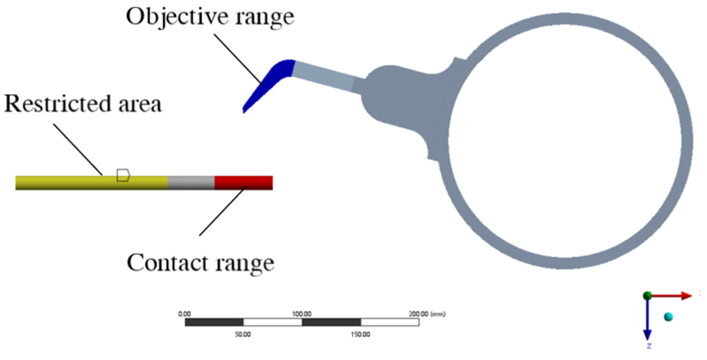
(3)
The crushing process does not consider branch-to-branch interactions; the branch is fed at a horizontal angle, and displacement constraints are applied to some regions of the branch, as shown in Figure 1b.
After determining the simplification scheme, SolidWorks 2020 software is used to model the model in three dimensions, and three kinds of crushing models with tool cutting edge angles of 50°, 55°, and 60° are established, named M-50, M-55, and M-60, respectively. Each model consists of two entities, the branch and the knife roller, respectively, and the branch entity is partitioned to divide the mesh encryption region as well as the constraint region. The model is saved in Parasolid (.x_t) format and imported into ANSYS pre-processing SpaceClaim 2020 software, the global coordinate system of the model is defined at the center of the knife axis, and then the split branch entities are subjected to the shared topology operation to ensure the transfer of the branch model data during simulation.
Since the center of rotation of the rigid body in LS-DYNA software is the center of mass by default, and the actual center of rotation of the tool roll is at the axis of the tool shaft, it is necessary to import the model with the defined global coordinate system into SolidWorks, and find the mass and inertia tensor of the tool roll with respect to the global coordinate system (Ixx, Iyy, Izz, Ixy, Iyz, Ixz), so as to define the rigid body properties to determine the center of rotation during simulation in LS-DYNA. Define the rigid body properties to determine the position of the center of rotation for the simulation.

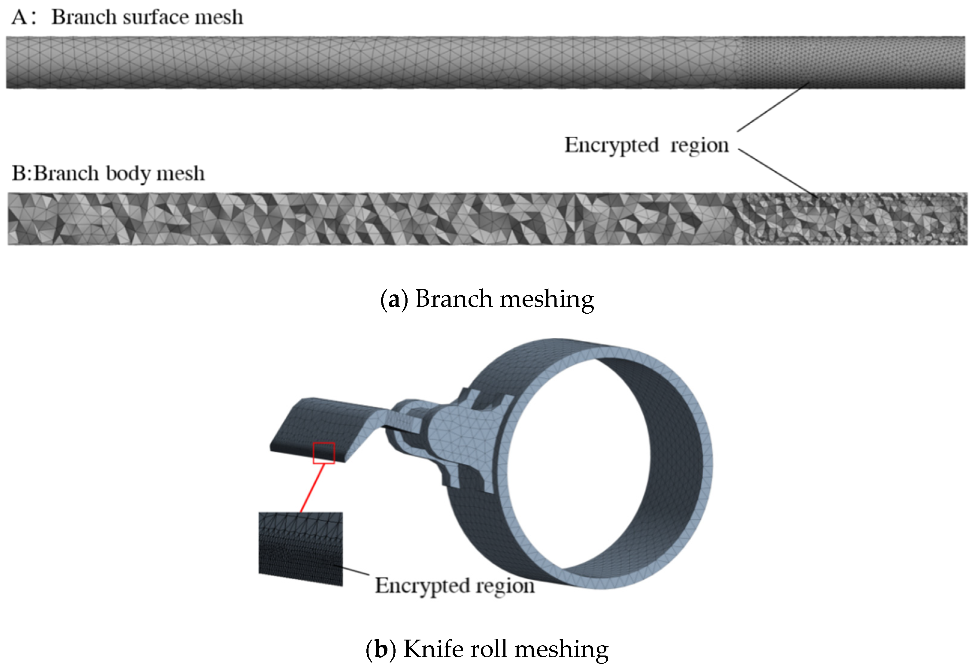
2.1.2. Crushing Model Material Definition and Meshing

(1)
Definition of model materials
After loading the LS-DYNA module in ANSYS, click on the engineering data column to define the material properties of the knife roller and branch. In this paper, the knife roller is defined as a rigid body, with a material density of 7.85 × 10³ kg/m3, a modulus of elasticity of 210 GPa, and a Poisson’s ratio of 0.3. According to the mechanical properties of the branch and the simplification requirements of the model in the previous stage, an isotropic elastic-plastic material model is selected for the branch material *MAT_PLASTICK_INEMATIC [6]. Combined with the relevant literature, the model material parameters are defined as shown in Table 1.
(2)
Model meshing
Mesh partitioning is an important part of the LS-DYNA simulation process, which determines the speed of simulation calculation as well as the solution accuracy. For the meshing of the crushing model, if the cell size is too large, it will be difficult to respond to the detailed process when the branch is damaged, but if the cell size is too small, the huge number of cells in the model will greatly increase the computation and the simulation cost [7,8]. Thus, the present model adopts the method of encrypting the local contact area for meshing.
All the geometry in the model is meshed using a tetrahedral meshing method and the algorithm is the patch conformal method, after which the regions are resized: branches’ encrypted area for face size meshing, cell size of 1 mm; branches’ encrypted area outside the part of the geometry of the cell size adjustment of 2 mm; knife roller geometry as a whole cell size adjustment of 10 mm; the tip of the knife part of the edge of the size adjustment of 1 mm; knife edge chamfering arc face size adjustment of 1 mm cell size. Three different tool edge angles of the crushing model, using the above method, were put in a mesh division, and the model M-50 division results are shown in Figure 2; skewness evaluation criteria were used to assess the quality of the model mesh division; the three models’ mesh division and quality assessment results are shown in Table 2; the average value of the skewness is less than 0.5.

2.1.3. Defining Contact Types, Constraints, and Analysis Settings

(1)
Define contact type
The contact in the crushing model is mainly the contact between the end of the crushing tool and the branch; when crushing, the end of the tool is not only in contact with the surface of the branch, but also invades into the branch geometry to generate contact and insert the “Contact Area” object into the “Connection” in the LS-DYNA interface. Insert the “Contact Area” object into the “Connection” in the LS-DYNA interface, specify the target area as the surface of the end of the tool (including 6 surfaces), and the contact area as the encrypted area of the branch model, as shown in Figure 3, and define the contact type as “Friction”. Set the coefficient of static friction between the tool and the branch to 0.39, and the coefficient of kinetic friction to 0.12. At the same time, insert the “Contact Characteristics” into the solver and define the type as “Erosion”.
(2)
Defining constraints
The constraints in the crushing model include the constraints of the branch and the constraints of the knife roller. The displacement constraints are defined for the branch in the solver, with the x and y components set to free and the z component set to 0 displacement. Since the knife roller attribute is a rigid body, the knife roller rotates around the axis in the crushing process, so the rigid body constraint is added to the knife roller, which is set to rotate freely around the y-axis, and the remaining five degrees of freedom are set to be fixed; the center of rotation of the knife roller is the center of mass of the rigid body in LS-DYNA by default, so it is necessary to define the attribute of the rigid body in the solver in order to ensure that it rotates around the knife axis, and the mass and inertia tensor of the knife roller is inputted into the solver according to the pre-solved mass and inertia tensor of the knife roller in relation to the global coordinate system. For the mass and inertia tensor, input the inertia parameters, and define the coordinates of the rotation center (x, y, z) as the position of the origin of the global coordinate system.
(3)
Analytical settings
Since the present study is to explore the comminution problem at different speeds, the comminution knife roller speeds were set to 1.7 × 10³ r/min, 2.1 × 10³ r/min, and 2.5 × 10³ r/min, respectively. If the force constraint is not applied to the knife roller rigid body in the simulation process, and only its initial rotational speed is set, some of its kinetic energy will be converted into internal energy and the kinetic energy of the branch when the rigid body is in contact with the branch, which leads to a decrease in the rotational speed of the rigid body in the crushing process; it is not possible to ensure that the rigid body rotates at a uniform speed, and the actual force of the rigid body is more complicated, so it is necessary to apply a forced node rotation associated with the time to the rigid body.
Define the end time as the rotation time of the rigid body in the analysis settings, insert “Rigid Body Rotation” into the solver and define its rotation size around the y-axis as “Table Data”, enter the linear data of rotation angle and rotation time in “Table Data”, and define the initial time and initial angle under the conditions of 1.7 × 10³ r/min, 2.1 × 10³ r/min, and 2.5 × 10³ r/min for the three rotational speeds of the knife roller. In the “Table Data”, enter the linear data of rotation angle and rotation time, and under the conditions of three rotational speeds of 1700 r/min, 2100 r/min, and 2500 r/min of the knife roller, define the initial time and initial angle as 0, and the end time and angle as 3 × 10⁻³ s rotation of 30.6°, 2.38 × 10⁻³ s rotation of 30°, 2 × 10⁻³ s rotation of 30°, and 2 × 10⁻³ s rotation of 30°, respectively. Finally, set 100 equidistant points in the output control of the analysis setup, and add the equivalent force, overall hourglass energy, kinetic energy, and internal energy in the “solution” in order to analyze and study the whole crushing process.

2.2. Simulation and Analysis of Flow Field Characteristics in Pulverizing Device Based on CFD

When the branch crushing and collecting machine is in operation, the characteristics of the airflow field in the crushing device affect the feeding of branches, the quality of crushing, and the throwing of crushed materials; the high-speed rotation of the crushing knife rollers will especially make the crushing device form a complex flow field. This section will establish a simplified model of the crushing device of the branch crushing and collecting machine, based on the CFD numerical simulation method, using Fluent software, simulation, and analysis of the characteristics of the airflow field in the crushing device, to obtain the basic characteristics of the flow field in the crushing device, and to compare and analyze the distribution characteristics of the flow field under the conditions of different speeds of the crushing knife rollers in order to explore the influence of the speed of rotation on the branch feeding, crushing, and transporting, and provide a reference for the subsequent field test of the prototype.

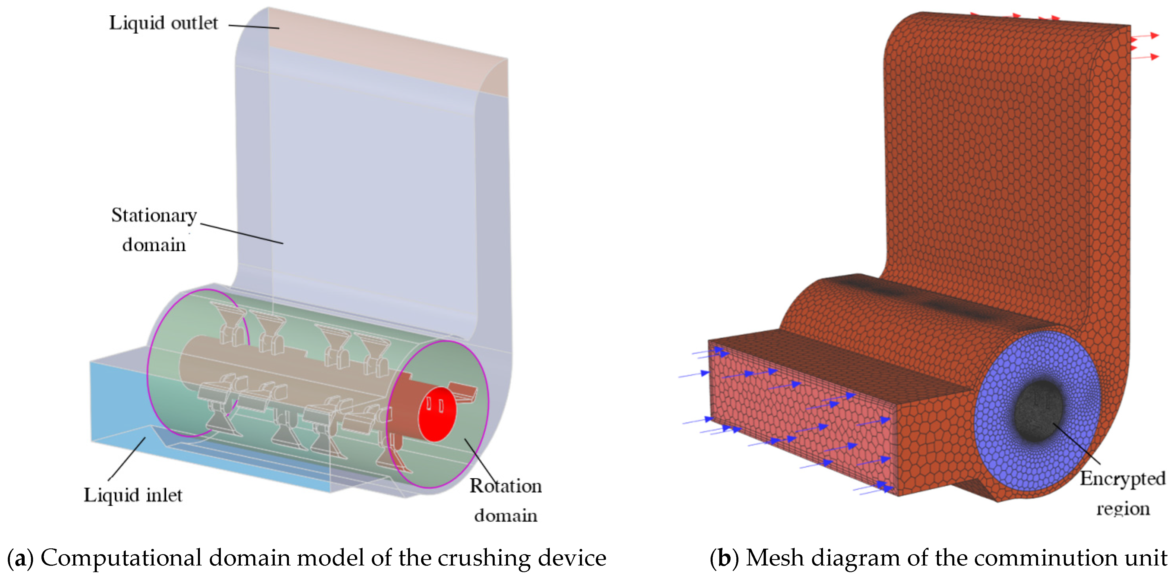
2.2.1. Crushing Device Model Building and Meshing

Establishing and simplifying the crushing device model is the basis for subsequent CFD simulation, the simulation before the simulation; first use SolidWorks software to establish the crushing knife roller, rotating area, and crushing the three-dimensional model of the cavity; in the process of modeling some of the structure of the simplified processing, do the following: neglect part of the chamfer of the hammer claw and the reinforcement; remove the bottom ends of the tool holder; ignore the connecting bolts and nuts, and consider the hammer claw and the tool holder and the tool shaft as a whole; ignore the shaft head at both ends of the tool shaft, and simplify the tool shaft to a through straight cylinder, so as to subsequently extract the domain of the fluid calculation. The established model file is saved in Parasolid (.x_t) format, imported into the ANSYS pre-processing software SpaceClaim Boolean operation, the rotational domain and static domain are extracted, and then the entire computational domain for the shared topology operation is extracted to ensure that the rotational domain and the static domain of the data transfer between the group for the model to create “NS”. In the group, “NS” is created for the model, and the inlet, the outlet, and the wall of the computational domain are selected and named; the processed 3D model is shown in Figure 4a.
After the model processing is completed, run ANSYS-Workbench and load Fluent (with Fluent Meshing) components, enter the Fluent meshing interface and select “Watertight Geometry” for meshing, and import the fluid calculation domain. Model mesh encryption on the wall of the crushing knife roller, and then generate the computational domain surface mesh. The geometric model is set to consist of a fluid domain with no voids, and the fluid–fluid boundary is changed from “wall” to “interior” to determine the boundary of the computational domain: the inlet and outlet are set to Pressure-inlet, Pressure-outlet, respectively, and all areas of the model are set to Fluid. Add a boundary layer to the computational domain model walls with an offset method type of Smooth-transition and other parameters as default. The Ploy-Hexcore method is applied to the computational domain for body meshing, which is well adapted to surfaces and produces a small number of meshes [9,10], resulting in a total of 1.49 × 10⁶ solid cells and 4.32 × 10⁶ mesh nodes. Automatic node movement is performed on the cell area to improve the grid quality, and finally the grid quality is evaluated by applying the skewness evaluation criterion; the average value of skewness is 0.066, the maximum value is 0.536, and the grid classification grade is “Excellent”.

2.2.2. Model Simulation Parameter Settings

(1)
Fluid flow control equations and turbulence model selection
In the branch crushing throwing process, branches in the crushing chamber after crushing are thrown through the discharge pipe, in which the crushed material is transported in the hammer claw and crushing device under the joint action of the airflow; to complete the crushing device in the form of air movement is actually gas–solid two-phase turbulent movement, but the direct analysis is difficult; the use of Fluent simulation software to analyze the crushing chamber of the gas-phase flow can be indirectly performed by crushing material motion form [11], a simulation and analysis process ignoring the air and the energy transfer between the crushed material and the crushing device within the gas-phase flow follows the law of conservation of mass and momentum. The mass conservation equation is as follows:
div ρ u ¯ = ρ u x + ρ v y + ρ w z
In the equation, div is the dispersion, ρ is the fluid density, and u, v, and w are the velocity vectors in the x, y, and z directions.
The momentum conservation equation is as follows:
ρ u t + div ρ u u ¯ = div μ g r a d u P w x + S U
ρ v t + div ρ v u ¯ = div μ g r a d v P w y + S V
ρ w t + div ρ w u ¯ = div μ g r a d w P w z + S W
In the equation, Pw is the pressure on the microproducts, t is the time, and, SU, SV, SW are generalized source terms.
The high-speed rotation of the knife roller in the crushing chamber will make the flow field in the crushing device produce a vortex phenomenon, so in the flow simulation process, the appropriate computational model needs to be chosen, in order to obtain the actual crushing chamber airflow characteristics of the similar results. The flow field in the crushing chamber in this study is dominated by turbulence, so a turbulence model is chosen for the simulation. The k-ε turbulence model in Fluent is computationally stable and efficient and is widely used in turbulence simulation [12,13]. The k-models include Standard k-ε, RNG k-ε, and Realizable k-ε models, among which Realizable k-ε models are more commonly used and can better solve turbulent flow problems [14]. Therefore, the Realizable k-ε model is chosen in this simulation to simulate the airflow field in the crushing chamber, and the transport equations for k and ε are given in Equations (5) and (6).
ρ U j k x j = μ l + μ t σ k 2 k + μ t S t 2 ρ ε
ρ U j ε x j = μ l + μ t σ ε 2 ε + C 1 S t ρ ε C 2 ρ ε 2 k + v ε
In the equation, C1 = max [0.43,η/(η + 5)], C2 = 1.0, Uj is the fluid velocity, k is the turbulent kinetic energy, μt is the effective viscosity, ε is the turbulent dissipation rate, xj is the component of x in the j-direction, St is the generating term of turbulent kinetic energy, σk is the Prandtl constant related to the turbulent kinetic energy taken as 1, σ is the Prandtl constant related to the turbulent dissipation rate taken as 0.7179, η is the strain rate, C1, C2 is the constant coefficient on the turbulence dissipation, C1 taken as 1.42, C2 taken as 1.68 [15].
When using Fluent software to simulate and analyze the airflow field inside the crushing chamber, the Navier–Stokes control equation used to solve the airflow field is
t v a ρ a ε a + v a 2 ρ a ε a = P + μ a v a + v a T + v a ρ a g F c i
In the equation, va is the gas-phase fluid velocity vector, and Fci represents the momentum sink. Referring to the relevant literature, it can be seen that the turbulent velocity and pressure of pumps, fans, and other systems are basically constant and time-independent, which is called the time-averaged value when the system works stably. The turbulence can be expressed by the time-averaged motion parameters called time-averaged turbulence, and the turbulence can be regarded as constant flow; at this time, the continuity equation, kinetic energy equation, and Bernoulli’s equation can be applied to the time-averaged turbulence [16].
(2)
Parameter setting
After the mesh division is finished, the simulation operation condition is set to double precision in Fluent, and after entering the solution interface, the mesh is checked firstly to make sure that there is no negative volume, and then the parameter setting is continued with. In the simulation, the flow field is regarded as incompressible, the fluid medium is set as air, and the steady state, pressure-based solver is selected. The working conditions of the computational domain are set, the gravitational acceleration is 9.8 m/s2 in the negative direction of the z-axis, and the operating pressure is 1.01 × 10⁵ Pa (one standard atmospheric pressure). The rotational domain is defined using the multiple reference system model (MRF): according to the demand of this simulation analysis, the knife roller speed is set to 1.7 × 10³ r/min, 2.1 × 10³ r/min and 2.5 × 10³ r/min, respectively; the rotation threshold is defined as rotating around the center axis, i.e., the y-axis, in the positive direction. The inlet and outlet of the computational domain are set as pressure inlet and pressure outlet, respectively, and the gauge pressure at the inlet and outlet are set to 0 Pa. The solution method is the pressure–velocity coupling algorithm for steady state computation. The scheme is Simple, the pressure interpolation algorithm is the PRESTO algorithm, which is suitable for high Xuan-flow, and the pressure changes rapidly in the fluid domain [17,18,19]; the momentum, turbulent kinetic energy, and dissipation rate are all in the Second Order Upwind format, which has a high computational accuracy [20], the Warped-Face gradient correction is chosen, and the sub-looseness factor is the default value. The subrelaxation factors are all default values. After initialization of the mix, set the number of operation iterations to 2000, after which the calculation starts until convergence. After convergence, the entry and exit mass flow reports are viewed and the difference between the entry and exit flows is calculated to be less than 0.5% to ensure that the simulation results are valid.

2.3. Crushing Knife Roller Modal Analysis

In crusher crushing operations, crushing knife roller rotation is the main source of vibration of the machine, and the resonance will cause the connected machine parts to loosen, and even some parts of the hazard to crack; thus, it is necessary to carry out a modal analysis of the knife roller, in order to determine the crushing of the knife roller modal attributes and the relationship between the frequency of excitation and the rotation of the predictive dynamic performance of the equipment [21], so as to avoid resonance of the branch crushing and collecting machine in the work. The phenomenon of resonance in the operation of the branch crusher and collector can be avoided.
In the theory of classical mechanics, the kinetic equation of an object is shown in Equation (8):
[ M ] { x ¨ } + [ C ] { x ˙ } + [ K ] { x } = { F ( t ) }
In the equation,
[M]—System quality matrix;
[C]—System damping matrix;
[K]—Stiffness matrix;
{ x ¨ } —System unit node acceleration vector;
{ x ˙ } —System unit node velocity vector;
{ x } —System unit node displacement vector;
{ F ( t ) } —Force vector.
In practice, the structure’s intrinsic frequency and vibration mode are affected very little by its own damping, and this affect can be ignored. If the structure is free of vibration in the analysis, the structural modes are determined only by its own characteristics and the external load has nothing to do with it; given that the force vector F(t) = 0 in Equation (9), ignoring the damping [C], the dynamic equation of undamped free vibration is
[ M ] { x ¨ } + [ K ] { x } = { 0 }
A structure in a state of free vibration with each mass point vibrating in simple harmonic vibration near its equilibrium position [22], and the expression for the vector of vibration displacements of the mass points is
{ x } = { x 0 } cos ω t
In the equation,
{x0}—Amplitude vector;
ω—Frequency of oscillation pattern.
Associative Equations (9) and (10) can be obtained.
( [ K ] ω i 2 [ M ] ) { x } = 0
The eigenvalue is ωi2, ωi is the self-oscillating circumferential frequency, i is the number of degrees of freedom, the eigenvector corresponding to the eigenvalue ωi2 is the vibration mode corresponding to the self-oscillation frequency f = ωi/2π [23,24,25]. Show that modal analysis is essentially the process of solving eigenvalues and eigenvectors, also known as modal extraction [26].

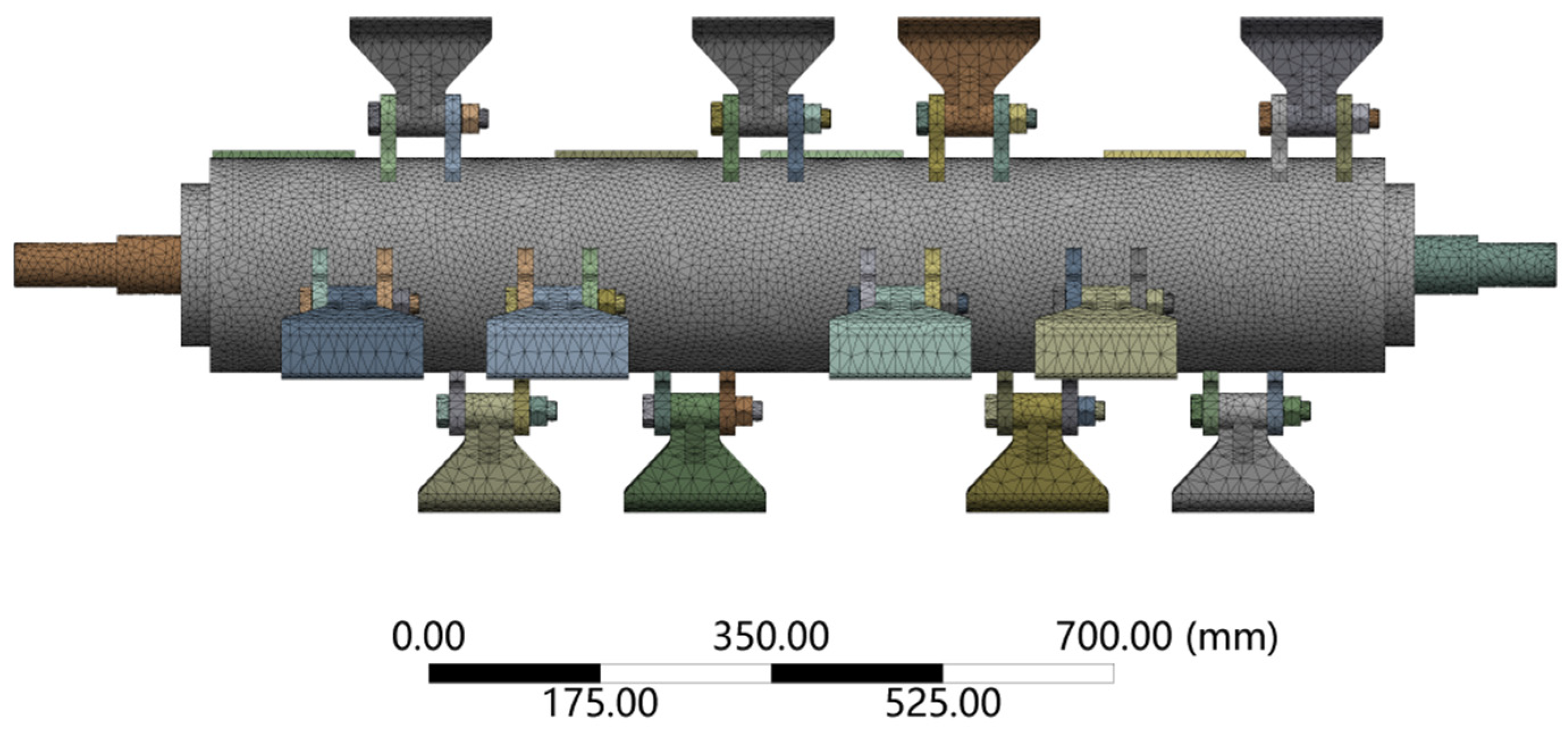
Crusher Roll Modeling and Meshing

SolidWorks 2020 software is used to establish a three-dimensional model of the crushing knife roller, omitting details such as keyways and threads that do not have much influence on the modal analysis of the system, saving the file in Parasolid (.x_t) format, invoking the Model module in ANSYS Workbench 2022 R1, importing the three-dimensional model, and using the DesignModeler plug-in to perform co-nodal operations on the components in the geometry. The generated new parts are given the corresponding material, in which the material of the knife shaft and knife seat is Q235, the material of the hammer claw is 65Mn, and the material of the axle head is No.45 steel; the three kinds of steel have similar values of density, modulus of elasticity, and Poisson’s ratio parameter, and the following materials are used for each part of the crushing knife roll in the simulation: the density is 7.85 × 10³ kg·m−3, modulus of elasticity is 210 GPa, and Poisson’s ratio is 0.3 [27].
All contacts in the connection are removed and the model is automatically meshed, where the cell size is set to 10 mm and the dimensional resolution is set to default. The division produces a total of 3.07 × 10⁵ grid nodes and 1.69 × 10⁵ entity cells. Afterwards, cylindrical support constraints are added at the mating point of the shaft head and bearing for constrained modal analysis, and no external force is applied to the whole model [21]. As shown in Figure 5.
For the mesh quality metrics, ANSYS Workbench has aspect ratio, Jacobi ratio, skewness, maximum corner angle, and warpage angle, etc. Skewness is one of the commonly used criteria for meshing quality, and the closer the skewness is to 0, the better the mesh quality is. The average value of the mesh skewness of the knife roller model is 0.43. Referring to the comparison table of skewness and mesh quality in the literature [28], it can be seen that the mesh classification is “Good”, which meets the computational accuracy requirements for the subsequent modal analysis of the knife shaft.

3. Results

3.1. Results of Simulation and Analysis of Branch Crushing Process

The simulation study of the branch crushing process was carried out under the conditions of different knife roller speeds and different tool edge angles; a total of five simulations of the overall hourglass energy to total energy ratio were less than 5%, indicating that the model numerical fit was reasonable and the simulation results were reliable [29,30]. Figure 6 gives the branch cutting process under the parameter conditions of knife axis speed of 1700 r/min and tool edge angle of 55°. It can be seen that the cutting process of the tool includes four positions of preparing to cut, start cutting, deep cutting, and cutting completion, of which the deep cutting also includes the position of the maximum stress position and the lower part of the disconnection position, as shown in Figure 6a–f.
At the starting moment in Figure 6a, when the tool is about to make contact with the branch, the equivalent force is zero; initial contact between the branch and the tool occurs at 1.14 × 10⁻³ s. Due to the high rotational speed of the tool, the branch is subjected to a large impact and the load changes abruptly, at which time the maximum equivalent force reaches 24.724 MPa; Figure 6d shows the branch cutting state when the maximum equivalent force of the whole crushing process occurs; the time of occurrence is 1.32 × 10⁻³ s, the branch produces a large deformation, and at this time the size of the equivalent force is 43.175 MPa; at 1.38 × 10⁻³ s, the branch breaks off from the cut opposite side, as shown in Figure 6e; the branch finishes cutting at 1.62 × 10⁻³ s. As shown in Figure 6f, the uneven cut section of the branch can be fully observed, and at this time, the branch is still in the bending state, and there exists internal stress, with the maximum value of equivalent stress of 33.345 MPa. From the whole cutting process, it can be seen that the destruction process of the branch not only exists in the tool cutting, but also in the bending and breaking of the opposite side of the cutting place, so that the branch crushed will present an irregular cutting section.
(1)
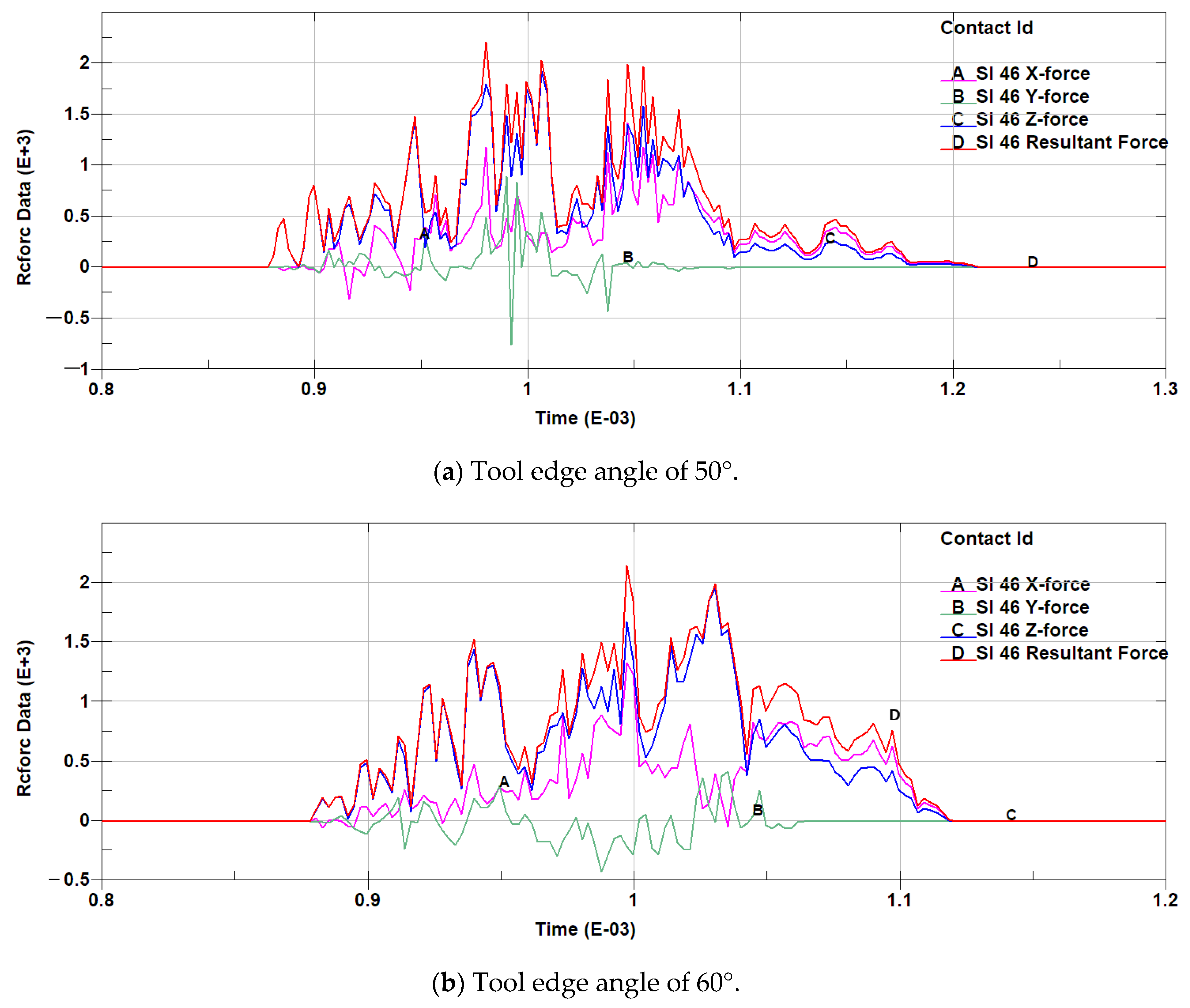
Simulation analysis of the crushing process at different knife roller speeds
In the crushing process, crushing knife roller speed is a key factor affecting the cutting force; in the simulation analysis of the knife edge angle of 55°, the knife roller speeds were 1.7 × 10³ r/min, 2.1 × 10³ r/min, and 2.5 × 10³ r/min. LS-DYNA simulation analysis andpost-processing software LS-Prepost were used to open the generated d3plot * as well as the rcforce* files, to produce the cutting force–time curve in the branch crushing process, and to facilitate the cutting process of the cutting force in all directions and the cutting force analysis. The generated cutting force–time curves are shown in Figure 7a–c, where time (Time) is in s, contact force (Rcforce Data) is in N, and the horizontal coordinate time range is taken as the effective cutting period of the branch.
Analysis of Figure 7a–c shows that under the three rotational speeds of 1.7 × 10³ r/min, 2.1 × 10³ r/min, and 2.5 × 10³ r/min, the cutting force of the knife oscillates with time, which is due to the fact that in the simulation process, the unit within the branch model is damaged after the strain generated exceeds its permissible strain as the knife cuts deeper, and part of the force will be unloaded. Further analysis shows that the simulation process of three different knife roller speeds, with the increase in rotational speed of the branch cutting process, will be completed in a shorter period of time, the cutting process in the Y-direction cutting force is shorter, the maximum value of the Z-direction cutting force is the largest, and the maximum value of the cutting force in the X, Z direction increases as rotational speed increases, from small to large with three speeds of the cutting force (the value of the reaction on the tool for the resistance to cutting). The maximum values are 1.71 × 10³ N, 1.86 × 10³ N, 2.69 × 10³ N, corresponding to the times of 1.21 × 10⁻³ s, 1.03 × 10⁻³ s, and 8.34 × 10⁻⁴ s, respectively, as shown in Figure 8. It can be seen that the maximum value of the cutting resistance also increases with the increase in the rotational speed of the knife roller, and the maximum value of the time of occurrence also increases. Through the above analysis, it can be seen that in the crushing process, increasing the knife speed will enhance the crushing efficiency, but the knife cutting resistance will also increase, so in order to meet the conditions of branch cutting, a knife roller speed in the low range should be selected.
(2)
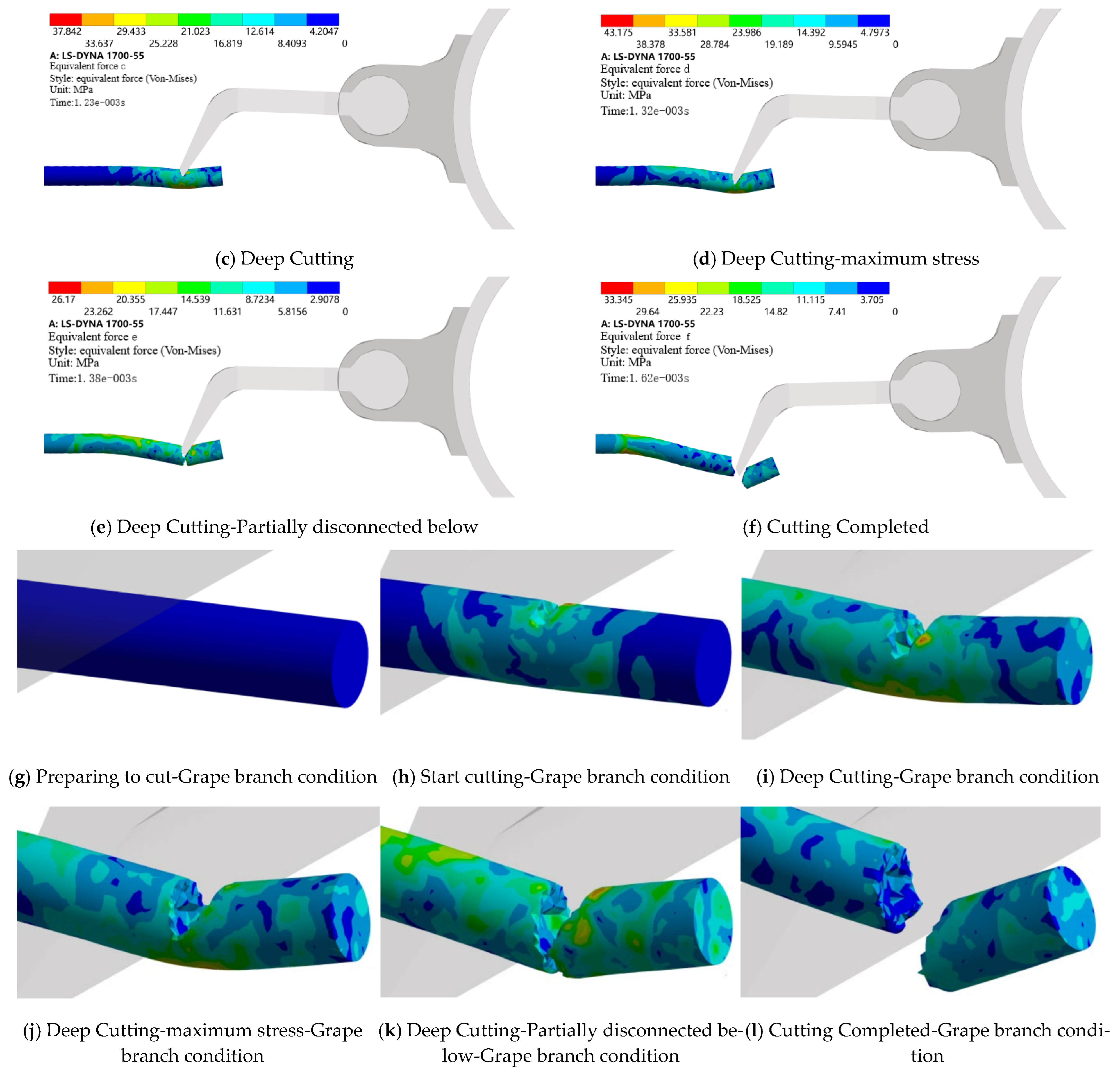
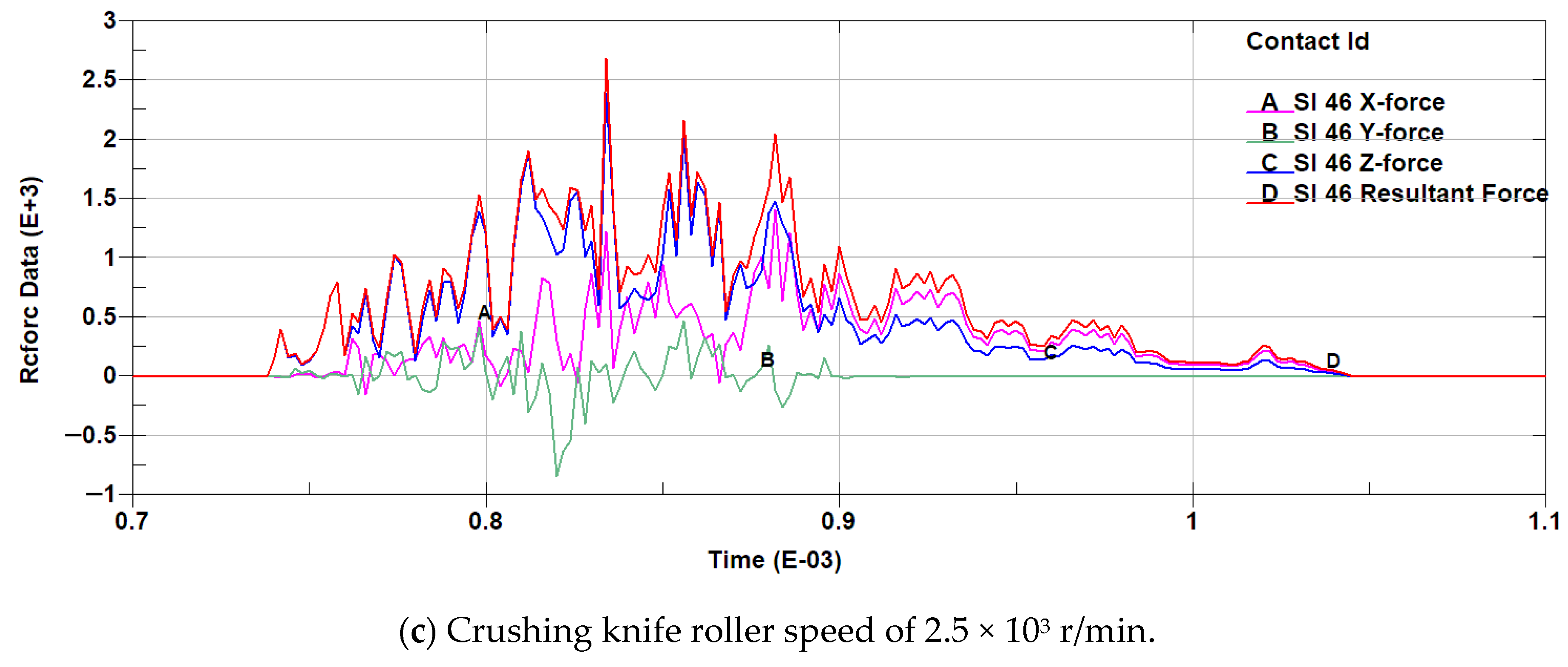
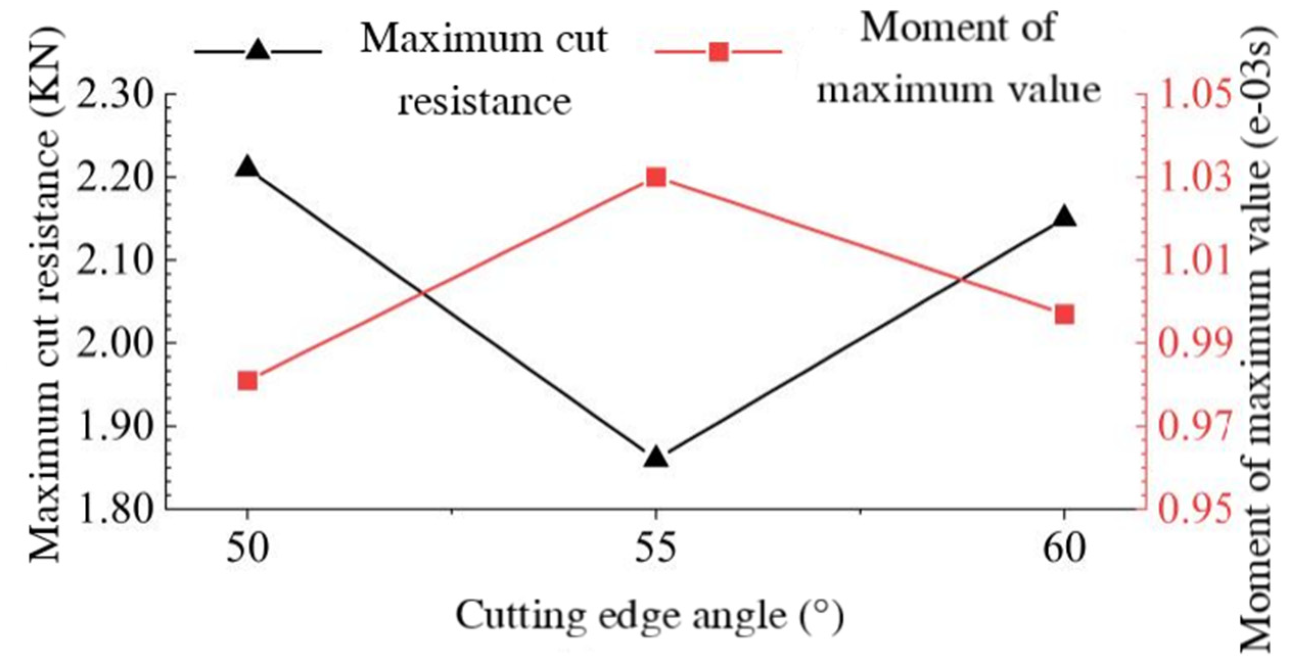
Simulation analysis of comminution process under different tool edge angles
Figure 7b and Figure 9a,b reflect the cutting force–time curves at the knife roller speed of 2100 r/min and the tool edge angles of 50°, 55°, and 60°, respectively. It can be analyzed that the effective cutting time decreases accordingly with the increase in the tool edge angle; the cutting force is smaller in the Y direction during the cutting process and the largest in the Z direction, and the maximum cutting force is the smallest in the X and Z directions at the edge angle of 55°. When the cutting angle is 55°, the maximum cutting force in the X and Z directions is the smallest. The maximum value of the combined cutting force of the tool with 50°, 55°, and 60° cutting edge angles is 2.21 × 10³ N, 1.86 × 10³ N, and 2.15 × 10³ N, respectively, and the corresponding time is 9.81 × 10⁻⁴ s, 1.03 × 10⁻³ s, and 9.97 × 10⁻⁴ s, respectively, which is shown in Figure 10; it can be seen that the maximum value of the combined cutting force is the smallest when the cutting edge angle is 55°. Therefore, under a certain rotational speed, the cutting resistance is the smallest when the cutting edge angle of the tool is 55°, which is more suitable for the crushing and cutting of grapevine branches.

3.2. Simulation Results of CFD-Based Flow Field Characteristics in Pulverizing Device

After the end of the flow field simulation operation, the results will be imported into the CFD-Post software for post-processing of the simulation results, in order to provide a more intuitive description of the flow field distribution characteristics of the crushing device, and to establish seven representative two-dimensional cross-sections in the computational domain and the locations of the cross-sections, as shown in Figure 11.
The P1 cross-section is at the left boundary of the computational domain, parallel to the XZ plane and Y = −580 mm; the P2 cross-section is a symmetric plane at the center of the computational domain; the P3 cross-section is in the right region of the fluid domain, parallel to the XZ plane and Y = 310 mm; the P4 cross-section is close to the inlet region and passes through the end of the hammer claw, parallel to the YZ plane and X = 271 mm; the P5 cross-section is overlapped with the YZ plane and passes through the axial line of the knife roller; P6 is located at the bottom of the calculation domain, parallel to the XY plane, Z = −250 mm; P7 is located in the middle and lower part of the discharge pipe, parallel to the XY plane, Z = 500 mm.
(1)
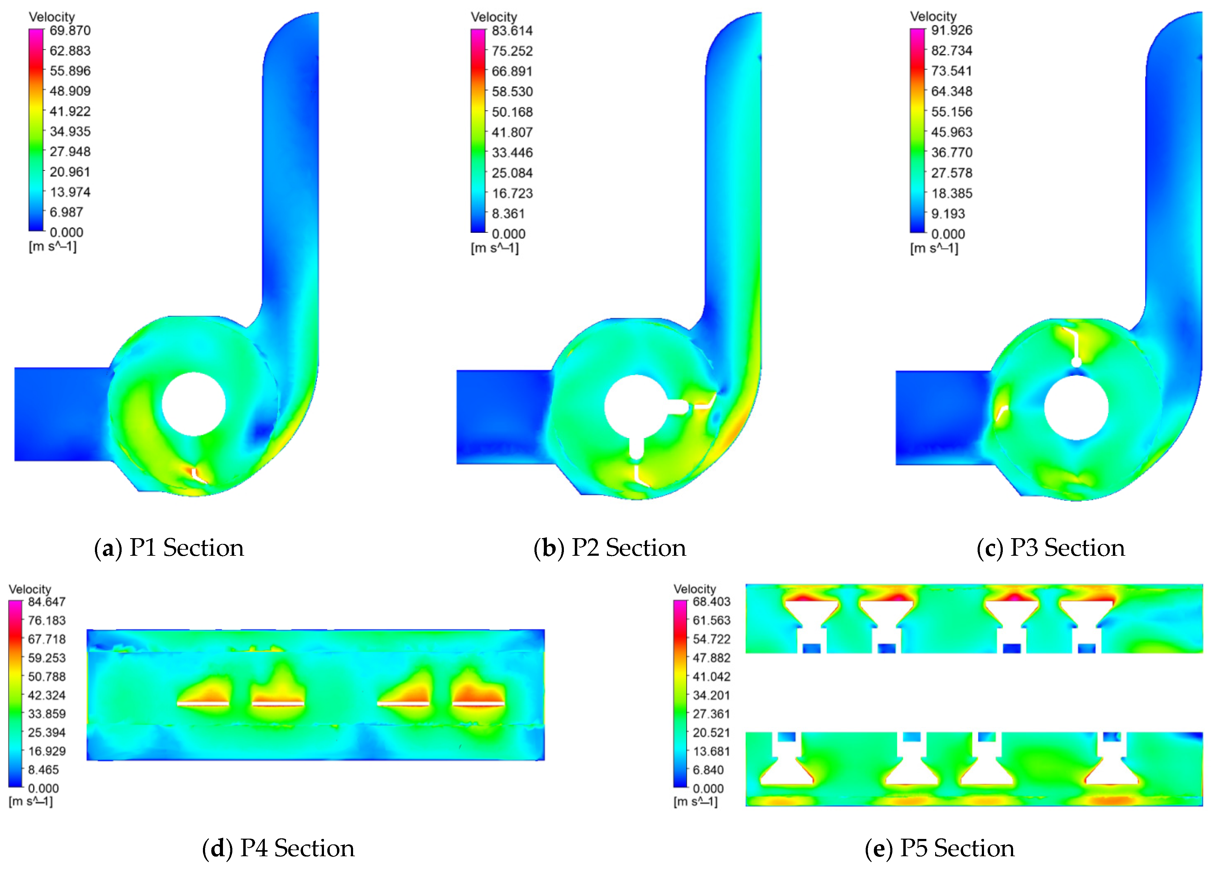
Crushing indoor velocity field analysis
In this section, the velocity field inside the crushing device is analyzed at a knife roller speed of 2.1 × 10³ r/min, and the velocity cloud of the P1~P7 cross-section is shown in Figure 12. From the P1~P3 and P5 cross-section velocity cloud diagrams, it can be seen that the airflow velocity in the inlet area is lower, and the flow velocity at the bottom area of the inlet is higher; the mean values of the P1~P3 cross-section velocities are 21.383 m/s, 27.553 m/s, and 28.063 m/s, and it can be seen that the average velocity in the computational domain located in the boundary is lower, the average velocity located in the center area is higher, and the change is not. It can be seen that the average velocity in the calculation domain is lower at the boundary, and the average velocity in the center area is higher and does not change much; the air velocity in the rotating area of the knife roller is higher, the air velocity in the rotating area is increasing along the radial direction of the knife roller, and the air velocity decreases from the rotating area into the discharge pipe. From P4 and P6 cross-sections, it can be seen in the tool leeward area that the airflow velocity is higher than in the windward area; from P1~P3, P7 cross-sections, a velocity cloud can be seen, the discharge pipe near the right side of the crushing device is higher than the speed of the left side of the region near the speed, and the central region of the highest speed, which is consistent with the theoretical design of the crushing device. The high-speed rotation of the knife roller will also be in the knife roller rotating region of the outer surface of the formation of the circulation layer, as shown in Figure 12a,c, due to the design of the hammer claw for the asymmetric helical arrangement, which to a certain extent inhibits the formation of the circulation layer; in the actual design of the crushing chamber, it should also be added to the wall of the spoiler teeth, in order to destroy the circulation layer to allow the branch to be fully crushed and smoothly thrown out by the discharge pipe.
(2)
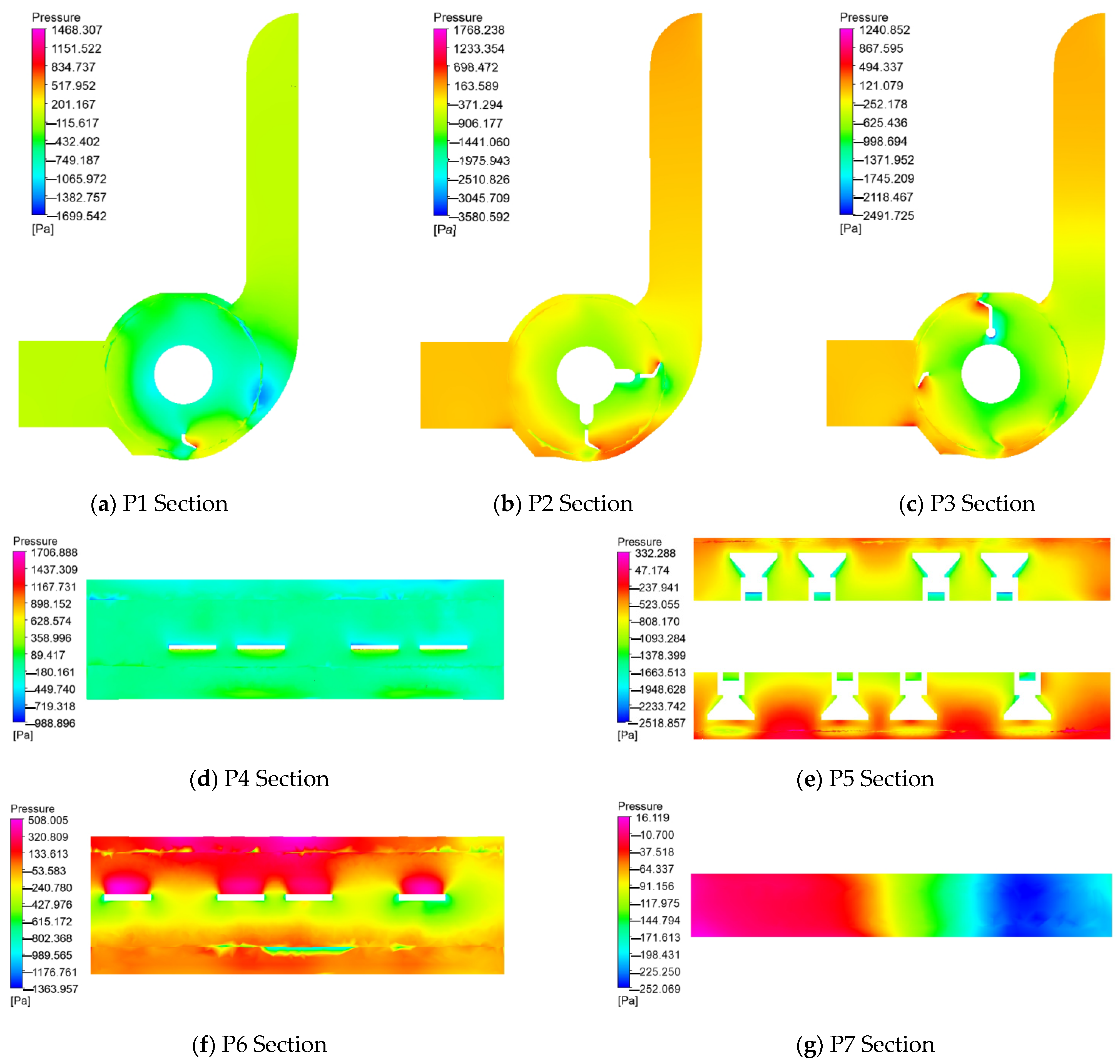
Pressure field analysis inside the crushing chamber
Figure 13 and Figure 14 show the pressure distribution on the surface of the crushing knife roller and the cross-section of P1~P7 when the knife roller rotates at a speed of 2.1 × 10³ r/min. It can be seen in Figure 13 that the pressure on the windward side of the crushing knife roller shows a gradient distribution along the radial direction, and along the radial direction of the knife roller from the cylindrical surface of the cutter shaft to the top of the hammer claw, the pressure is constantly increasing; combined with the pressure cloud diagrams of the cross-sections of P1~P3 and P6, the pressure on the windward side of the tool is significantly higher than that of the surrounding area. The pressure near the windward side of the tool is obviously higher than the surrounding area, and the higher pressure on the windward side of the hammer and claw-type tool is related to the work done on the windward side of the fluid [31]. The pressure on the windward side of the tool shows discontinuous variations, with the pressure at the bottom and end of the tool being higher than that in the central region, the pressure on the windward side of the tool being lower than that on the windward side, and there being a negative pressure zone around the tool. The change in tool leeward pressure occurs at the corner of the hammer jaw bend, indicating that the change in tool shape also leads to pressure fluctuations in the nearby area.
The pressure distribution of the P1 to P7 sections is presented in Figure 14. From the P1~P3 and P5 cross-section pressure clouds, it can be seen that in the whole crushing device, the pressure change in the feed inlet area and the discharge pipe close to the exit area is not big. The average values of the pressures of the P1~P3 sections are −512.273 Pa, −657.452 Pa, and −585.193 Pa, respectively, which shows that in the crushing device, the pressure value of the central area where the P2 section is located is lower. In the knife roller rotary area, due to the high-speed rotation of the knife roller, the pressure fluctuation is more obvious in the rotary area, forming a large area of negative pressure, and the closer to the knife shaft surface, the lower the negative pressure value. The P4 cross-section pressure cloud reacts to the pressure distribution at the junction of the inlet area and the crushing chamber, where the pressure value fluctuates less and the average pressure value is −80.954 Pa. The P7 cross-section pressure map can be seen in the cross-section of the discharge pipe near the rotating domain of the existence of negative pressure areas, and due to the influence of the right spiral arrangement of the hammer claw, the right side of the discharge pipe pressure value is lower than that of the left side, and the pressure value of the region presents a gradient distribution, so the hammer claw adopts the right spiral arrangement of a low vibration; the cutter shaft is uniformly affected by the characteristics of the force, but it is necessary to consider the arrangement of the influence of the uniformity of the material thrown.
(3)
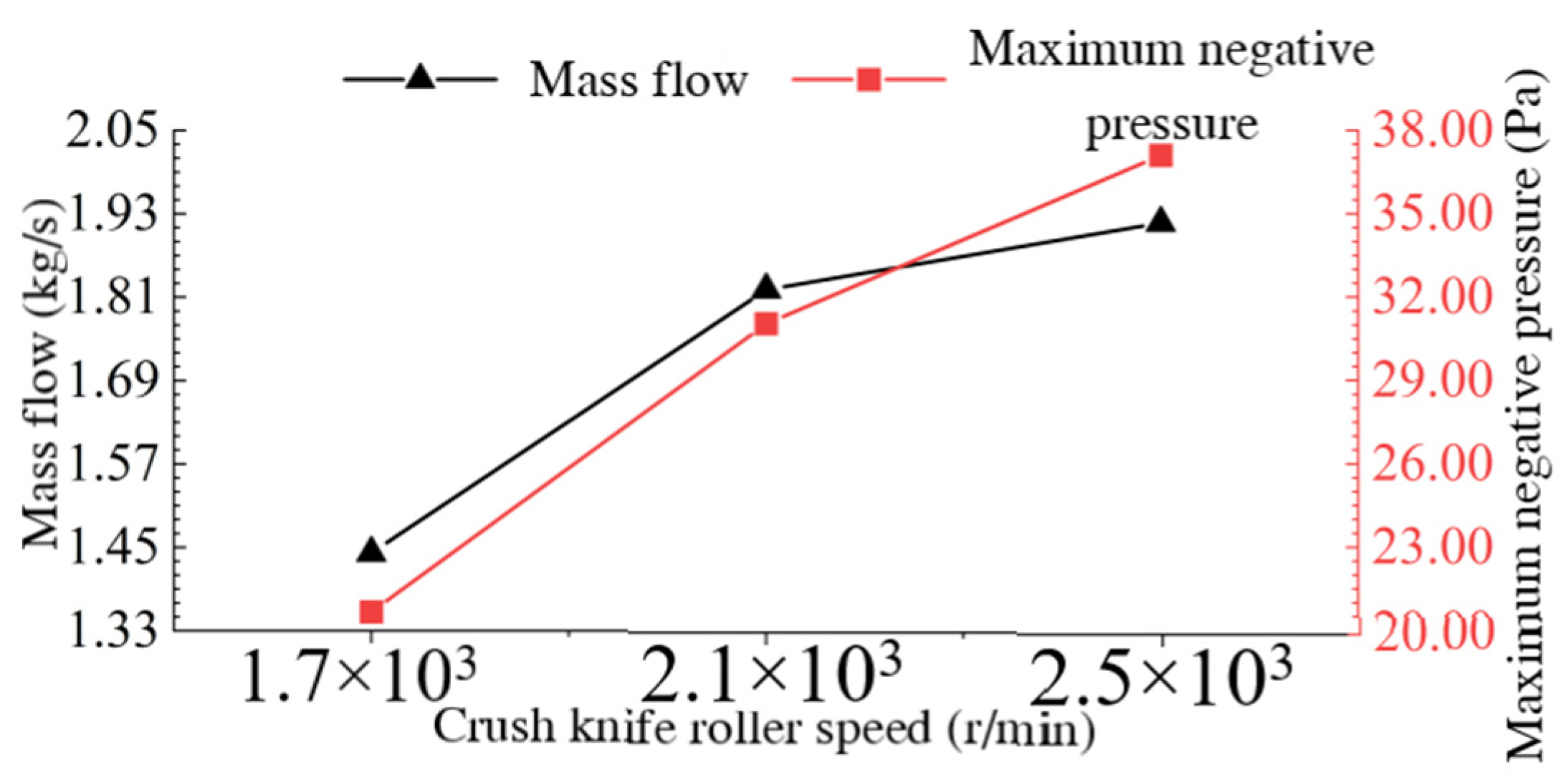
Characterization of the flow field in the crushing chamber at different knife roller speeds
The rotational speed of the crushing knife roller is the key working parameter of the branch crushing and collecting device, and this study will further analyze the effect of rotational speed on the branch feeding, crushing, and crushed material throwing by comparing the distribution of the airflow field in the crushing device under different rotational speeds. The speed of the crushing knife roller was set to 1.7 × 10³ r/min, 2.1 × 10³ r/min, and 2.5 × 10³ r/min, and after the calculation, the post-processing software CFD-Post was used to calculate the inlet flow rate and generate the inlet pressure map and cross-section flow map for analysis and research.
Figure 15a–c, respectively, represent three knife roller speed inlet pressure clouds; three speed inlet areas are large negative pressure areas, and positive pressure areas are present at the bottom of the inlet position, which is related to the bottom of the existence of the vortex; the maximum values of the inlet negative pressure were 20.65 Pa, 31.05 Pa, and 37.16 Pa, as shown in Figure 16, as can be seen with the increase in rotational speed of the entrance as the negative pressure maximum values increase. The maximum value of inlet negative pressure increases with the increase in rotational speed. As can be seen in Figure 14, the inlet mass flow rates at the three rotational speeds are 1.44 kg/s, 1.82 kg/s, and 1.92 kg/s, respectively, and as the rotational speed increases, the inlet flow rate also increases. Both the negative pressure at the inlet of the crushing unit and the increase in flow rate will induce more airflow from the inlet into the crushing unit, so increasing the speed of the crushing knife rollers during machine operation will be beneficial to the feeding of the branches.
Figure 17 shows the flow line diagrams of representative cross-sections P2 and P3 at different knife roller speeds, and it can be analyzed that the airflow velocity on cross-sections P2 and P3 increases as the speed increases. Three rotational speeds under the cross-section P2 streamline distribution changes which are not large, and are in the inlet and the knife roller rotating area and the junction of the discharge pipe to produce a vortex of similar size, so the knife roller speed changes on the cross-section P2; that is, the center of the crushing device region of the airflow mobility of the impact is small, only on the region of the airflow speed.
Vortices of different shapes and sizes are generated in the inlet area of cross-section P3, at the junction of the knife roll rotation area and the discharge tube, at the lower right side of the discharge tube, and at the middle-left side of the discharge tube. When the speed is increased from 1.7 × 10³ r/min to 2.5 × 10³ r/min, the vortex at the inlet area moves to the lower left, the vortex in the middle area of the left side of the discharge tube moves to the upper side, and the vortex strength there is obviously increased at 2.5 × 10³ r/min; when the speed is increased from 1.7 × 10³ r/min to 2.1 × 10³ r/min, the vortex at the junction of the rotating area of the knife roller and the discharge tube and at the lower right side of the discharge tube is weakened. However, when the rotational speed is increased from 2.1 × 10³ r/min to 2.5 × 10³ r/min, the vortex at the junction between the rotating area of the knife roller and the discharge tube is significantly enhanced, and the vortex area at the right bottom of the discharge tube is significantly larger, its diameter being almost equal to the cross-section width of the discharge tube. Therefore, the variation in the speed of the crushing knife roller has a large effect on the airflow velocity as well as the airflow mobility at the cross-section P3.
In comprehensive analysis of the above, with the increase in the speed of the crushing knife roller, the crushing device at the exit of the airflow rate increases, and will increase the throwing speed of the material to a certain extent, but the knife roller speed being too high will also lead to the crushing device in part of the region enhancing the vortex, which affects the inlet of the branches of the feed and the crushed material thrown out of the discharge pipe.
Based on the tool dynamics analysis, branch crushing process simulation analysis, and the results of this section of the crushing device under the airflow field characteristics of different knife roller speeds, combined with the range of tractor output shaft speed, implement ratio, crushing power consumption, and other factors, the final determination of the crushing knife roller speed range was 1.8 × 10³~2.22 × 10³ r/min.

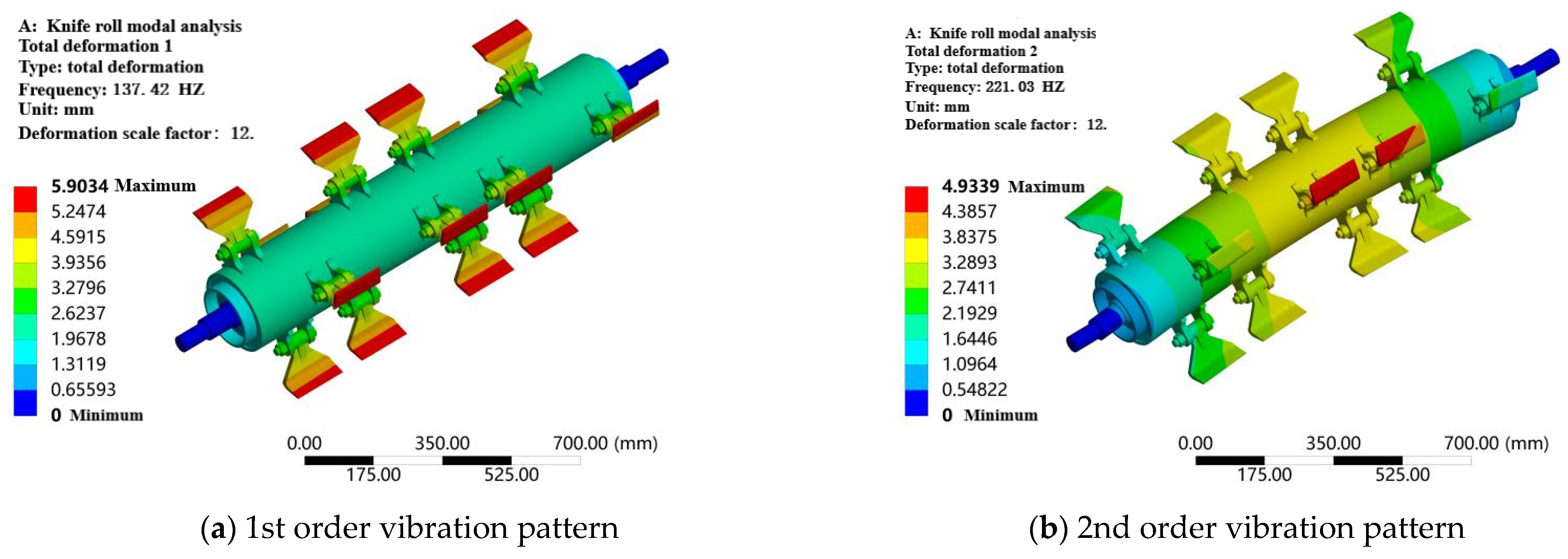
3.3. Crushing Knife Roller Modal Analysis Results

Generally speaking, the low-order vibration of the mechanism of the dynamic impact of the device is more significant, so the selection of the first 5 to 10 orders for analysis has been sufficient [21,32]. This paper combines the characteristics of the crushing knife roller and similar devices’ modal analysis literature [33], analyzing the first six orders of the crushing knife roller natural frequency and vibration pattern. The results of the modal analysis are summarized, and the intrinsic frequencies of each order are shown in Table 3. In order to facilitate the analysis, the deformation generated by the crushing knife roller is enlarged to show that the deformation scale factor is taken as 12, and the vibration pattern of each order is shown in Figure 18.
As can be seen from Figure 18, in the 1st order modal vibration mode, the deformation of the crushing knife roller for the overall radial tensile deformation and axial compression deformation is shown; in the 2nd and 3rd order modal vibration mode, the crushing rollers show a large bending deformation; this deformation is mainly concentrated in the middle part of the knife rollers, and the deformation at both ends is relatively small; in the 4th order modal vibration mode, the crushing shaft in the middle of the radial compression deformation and the deformation of the two ends is relatively small; the 5th and 6th order modal vibration modes in the crushing knife roller deformation are S-shaped near the head of the knife shaft to produce the opposite direction of radial deformation, and the knife roller in the middle position is not deformed. In the 4th order modal vibration mode, the middle of the crushing shaft produces part of the radial compression deformation, and the deformation at both ends is small; in the 5th and 6th order modal vibration modes, the crushing knife roller deformation is in the form of S, the radial deformation in the opposite direction is produced close to the head of the knife shaft, and the deformation in the middle of the knife roller is small. Meanwhile, combined with Table 2, it can be seen that the 2nd and 3rd order have similar intrinsic frequencies, and the 5th and 6th orders have similar shapes.
Knife roller operation has a maximum working speed of 2.22 × 10⁵ r/min; according to the frequency and speed of the relationship in the Formula (12), the operating frequency is 37 Hz, much smaller than the crushing knife roller lowest-order modal intrinsic frequency of 137.42 Hz; the crushing knife roller design is reasonable, and the machine will not resonate during operation.
v = 60 × f
In the equation,
v—Critical speed, r/min;
f—Intrinsic frequency, Hz.

4. Field Trials

Test time and place: October 2023, experimental field, Jinghe County, Bortala Bortala Mongol Autonomous Prefecture, Xinjiang Uygur Autonomous Region; test materials: winter pruned branches of Keresen Vineyard, grapevine planted with row spacing of 6 m and plant spacing of 0.6 m, average width of the pile of branches after pruning of 1.2 m, average height of 0.2 m. The average water content of the branches (including the leaves) was 61.48%, and the diameter was ≤60 mm.
Test apparatus: grape branch crushing and collecting machine prototype, tractor, tape measure, vernier calipers, pruning shears, table scale, electronic balance, drying box, tachometer (DT-2236B), stopwatch, dismantling tools. As can be seen from the figure, the field verification test crushing effect is basically similar to the theoretical value, and the prototype can meet the design requirements.
The operational performance of the grapevine branch crusher and collector was affected by the speed of the crusher rollers, the speed of the pickup rollers, and the ground clearance (distance between the end of the pickup teeth and the ground), which were therefore chosen as the test variables. The pickup roller speed was controlled by adjusting the throttle valve in the hydraulic circuit, the crushing knife roller speed was realized by changing the pulley to adjust the transmission ratio, and the ground clearance of the pickup toggle was adjusted by changing the implement slide plate.
Considering the cutting resistance of the crushing knife, the characteristics of the flow field in the crushing device, the range of tractor output shaft speeds, the gear ratio, the crushing power consumption, and other factors, the crushing knife roller speed selection range is as follows: 1.8 × 10³ r/min, 2.01 × 10³ r/min, and 2.22 × 10³ r/min. For pickup roller speed selection in 80~120 r/min, take three levels: 80 r/min, 100 r/min, 120 r/min. The speed of pickup roller is selected from 80~120 r/min, and three levels are taken: 80 r/min, 100 r/min, 120 r/min. The ground clearance plays a key role in the branch pickup rate; referring to the related literature, the height of ground clearance ranges from 5 to 25 mm, and three levels are taken: 5 mm, 15 mm, 25 mm.
The two important performance indexes of the grapevine branch crushing and collecting machine are the picking up rate and crushing length qualification rate, which are calculated as follows:
Calculation of pickup rate: Before the test, the branches in each test area were weighed, and at the end of the test, the branches missed after the operation were collected and weighed, and the pickup rate was calculated according to Equation (13).
φ = m m 1 m × 100 %
where φ is the pickup rate, %; m is the total mass of branches in the measurement area, kg; m1 is the total mass of missed branches in the measurement area, kg.
Calculation of pulverized length qualification rate: collect and weigh the branches with pulverized length ≥ 150 mm among them and calculate according to Equation (14).
μ = m m 1 m 2 m m 1 × 100 %
where μ is the crushing length pass rate, %; m2 is the total mass of crushed unqualified branches in the measurement area, kg.
After the completion of grape branch pruning operations, the field test began in the test field; the length of each test area was taken as 20 m, the two ends of the measurement area were left 20 m of the stabilization area, and each test process to change the prototype’s operating state was consistent. The operating speed of the tractor during the test was controlled at 1.8 km/h. Before each test, the working parameters of the prototype were adjusted according to the test requirements.
The experimental results are shown in Table 4.
The test results are shown in Figure 19.

5. Conclusions

(1)
Through numerical simulation, using LS-DYNA software, combined with the measurement data of grapevine branch material characteristics in Section 2, the branch crushing process was simulated, the crushing process of the branch into the crushing chamber was analyzed, and the effects of different knife roller speeds and knife edge angles on the cutting resistance of the knife to crushing the branch were analyzed; the characteristics of the airflow field in the crushing device were analyzed using Fluent software, and the flow field distribution characteristics were compared under different knife roller speeds. The flow field characteristics in the crushing device were analyzed by Fluent software; the flow field distribution characteristics under different knife roller speeds were compared, the influence of the speed on branch feeding, crushing, and conveying was investigated, and the speed range of the knife roller, which can be used as a reference for the subsequent field test of the prototype, was finally determined; the modal analysis of the crushing knife roller was carried out on the basis of the ANSYS/Model module in order to prevent the resonance phenomenon from occurring in the operation of the machine.
(2)
Based on the branch crushing process simulation analysis, it is concluded that the branch in the destruction process not only exists in the cutting, but there is also the cutting of the opposing side of the bending fracture; with the increase in the speed of the knife roller, the cutting resistance of the tool continues to increase, and the cutting resistance reaches 2.69 × 10³ N at 2.5 × 10³ r/min; for the cutting angle of 55°, when the cutting resistance of the tool cutting the smallest, 1.86 × 10³ N, the blade angle is more suitable for the cutting of grapevines. The cutting angle is more suitable for the crushing and cutting of grapevine branches.
(3)
In the simulation analysis of the flow field of the crushing device, the velocity and pressure distribution law of the representative area of the crushing device are summarized; it is concluded that with the increase in the knife roller speed, the inlet flow and negative pressure of the crushing chamber increase, and the inlet flow and negative pressure at a speed of 2500 r/min are 1.92 kg/s and 37.16 Pa, respectively, which is conducive to the feeding of the branch; however, the speed is too high and it will lead to the enhancement of the vortex in some areas of the crushing device, which will affect the feeding of the branch at the entrance and the throwing of the crushed material in the discharge pipe. The crushing device in some areas enhances the vortex, which in turn affects the entrance of the branch feeding and the throwing of crushed material from the discharge pipe; combined with the analysis of the previous section, the final determination of the crushing knife roller speed range of 1.8 × 10³~2.22 × 10³ r/min. Based on the crushing knife roller modal analysis, the analysis of the first six orders of the knife roller natural frequency and vibration, the lowest order of the crushing knife roller’s modal natural frequency is 137.42 Hz, much larger than the crushing knife roller operating speed. If the crushing knife roller operating frequency is far greater than 37 Hz, the machine will not resonate.
In this paper, the research and development of a grape branch crushing collection machine, similar orchard branch crushing collection equipment designs provide reference. However, due to the limitations of my research and development time and design experience, research on the key device of the machine still needs to deepen, and there is room for optimization of the whole machine structure. Follow-up research and improvement work can be carried out on the following levels:
(1)
To further analyze the branch diameter, tool angle, tool center of mass, and other parameters on the branch crushing process of the cutting resistance of the tool; to study the crushing device structural parameters, the impact of the air field characteristics, and to carry out the gas–solid two-phase coupled flow simulation, in order to further improve the optimization of crushing device.
(2)
To affect the grape branch crushing collection machine’s performance of more factors, the follow-up can be further tests to analyze the machine’s other structural parameters such as pickup roller center distance, the number of knives, and the arrangement of the impact of the machine performance.
(3)
In order to ensure the performance of the machine on the basis of the lightweight improvement of the entire structure of the machine, and to reduce the manufacturing cost of the machine and its operational energy consumption.

Author Contributions

Resources, Z.W.; data curation, L.S.; writing—original draft preparation, L.H.; writing—review and editing, S.C.; visualization, P.B.; supervision, S.C.; project administration, L.H. All authors have read and agreed to the published version of the manuscript.

Funding

This work was supported by the Xinjiang Corps Young and Middle-aged Science and Technology Innovation Leaders Program, the Innovation Team of Xinjiang Academy of Agricultural and Reclamation Sciences and Xinjiang Corps key areas of science and technology research projects under project numbers 2020CB031, NCG202302 and 2024AB044, respectively.

Institutional Review Board Statement

Not applicable.

Informed Consent Statement

Not applicable.

Data Availability Statement

The data presented in this study are available on request from the corresponding author.

Conflicts of Interest

The authors declare no conflicts of interest.

References

  1. National Bureau of Statistics of the People’s Republic of China. China Statistical Yearbook; China Statistics Press: Beijing, China, 2021. (In Chinese)
  2. Xinjiang Uygur Autonomous Region Bureau of Statistics. Xinjiang Statistical Yearbook; China Statistics Press: Beijing, China, 2021. (In Chinese)
  3. Li, X.H.; Li, Y.J.; Ma, X.Q. Present situation and prospect of grape industry development in China. South China Fruits 2021, 50, 161–166. (In Chinese) [Google Scholar]
  4. Yang, C. Design and Test of Bionic Stubble Cutter Based on the Characteristics of Cricket Cutter Leaf; Anhui Agricultural University: Anhui, China, 2018. (In Chinese) [Google Scholar]
  5. Zou, Y. Research on Bionic Technology of Crushing Key Components Based on Corn Kernel Shaft Return Rotting; Jilin University: Jilin, China, 2023. (In Chinese) [Google Scholar]
  6. Tang, L.Y.; Tang, L.Y.; Li, P.N. Effect of cutting speed on chip morphology and machining surface micro -morophology. Modul. Mach. Tool Autom. Manuf. Tech. 2020, 5, 128–131. (In Chinese) [Google Scholar]
  7. Chen, L. Distribution law of damage zone of terrace rock body under mining blasting action Research. Blasting 2020, 37, 85–89. (In Chinese) [Google Scholar]
  8. Zhu, L.; Sun, Y.; Wang, H. Simulation of soil cutting by rotary tiller roller of micro tiller based on finite element method. J. Agric. Mech. Res. 2020, 42, 39–43. (In Chinese) [Google Scholar]
  9. Guo, W.; Jiang, Z.; Zhong, H.; Hou, R.; Xu, J. Impact of online mixing via KSM on the accuracy of ingredient deposition in manufacturing FGMs. Int. J. Mech. Sci. 2023, 241, 107971. [Google Scholar] [CrossRef]
  10. Wang, H.; Sun, W.; Zhao, C.; Zhang, S.; Han, J. Dynamic Modeling and Control for Tilt-Rotor UAV Based on 3D Flow Field Transient CFD. Drones 2022, 6, 338. [Google Scholar] [CrossRef]
  11. Tianguo, W.; Xingtian, C.; Weiyun, P.; Jiantuo, Z.; Fengwei, Z.; Jiajia, G. Research and prospect on mechanized harvesting technology of potato stalks and leaves silage. J. Chin. Agric. Mech. 2022, 43, 82–89. (In Chinese) [Google Scholar]
  12. Yu, W.L.; Ke, S.T. Flow field action and aerodynamic loads distribution for large-scale wind turbine under typhoon based on nesting of WRF and CFD. Acta Energiae Sol. Sin. 2020, 41, 260–269. (In Chinese) [Google Scholar]
  13. Di, Q.F.; Wang, N.; Chen, F. Research progress on the mechanical properties of threaded connections for oil country tubular goods. J. Shanghai Univ. (Nat. Sci. Ed.) 2020, 26, 163–180. (In Chinese) [Google Scholar]
  14. Tutar, M.; Oguz, G. Large eddy simulation of wind flow around parallel buildings with varying configurations. Fluid Dyn. Res. 2002, 31, 289–315. [Google Scholar] [CrossRef]
  15. Li, D. Research on Adsorption Picking Technology and Experiment on Yellow Silage Corn Stover with High Ground Clearance; Inner Mongolia Agricultural University: Inner Mongolia, China, 2023. (In Chinese) [Google Scholar]
  16. Liu, Z.Z. Bearing capacity of drill pipe joint thread of horizontal directional drilling machine and its structure optimization. Tunn. Constr. 2022, 42, 487–493. (In Chinese) [Google Scholar]
  17. Zheng, A.; Pan, G. Coupling analysis of hydraulic fracturing of crack in the heel of gravity dam. Hydro-Sci. Eng. 2022, 95–102. (In Chinese) [Google Scholar]
  18. Liu, P.; He, J.; Li, Y.; Li, H.; Wang, Q.; Lu, C.; Li, S.H. Design and experiment of double rollers maize stalk chopping device with different rotation speeds. Trans. Chin. Soc. Agric. Eng. 2020, 36, 69–79. (In Chinese) [Google Scholar]
  19. Shi, M.Y. Numerical Simulation Method and Flow Field Study of Multi-Fan Heat Pump Tibetan Medicine Drying Room; Yunnan Normal University: Kunming, China, 2022. (In Chinese) [Google Scholar]
  20. Zhao, Y. Analysis of Flow Field Characteristics and Aerodynamic Noise in a New Type of Forage Kneader; Inner Mongolia University of Technology: Inner Mongolia, China, 2023. (In Chinese) [Google Scholar]
  21. Niu, G.; Li, B.; Liu, Y. Vibration analysis and optimization of vertical straw crusher. J. Gansu Agric. Univ. 2021, 56, 185–194. (In Chinese) [Google Scholar]
  22. Feng, J.M.; Zhang, Q.Q.; Hou, T.F.; Peng, Y. Dynamics characteristics analysis of the oil-free scroll hydrogen recirculating pump based on multibody dynamics simulation. Int. J. Hydro Gen. Energy 2021, 46, 5699–5713. [Google Scholar]
  23. Ren, Z. Design and Experimental Research on Shear Device of Sea Buckthorn Harvester; Shihezi University: Xinjiang, China, 2023. (In Chinese) [Google Scholar]
  24. Fuqi, X.; Shijing, W.; Xiaoyong, L.; Xiaosun, W. Dynamic characteristics research of wind power planetary gear transmission system with tooth cracks. Comput. Integr. Manuf. Syst. 2022, 28, 2343–2352. (In Chinese) [Google Scholar]
  25. Étienne, A.; Pascal, L.; Luigi, M. The modal stability procedure for dynamic and linear finite element analysis with variability. Finite Elem. Anal. Des. 2010, 4, 30–45. [Google Scholar]
  26. Dou, T. Design and Experimental Research on Rice Straw Crusher; Northeast Forestry University: Heilongjiang, China, 2022. (In Chinese) [Google Scholar]
  27. Cheng, D. Mechanical Design Manual; Chemical Industry Press: Beijing, China, 2007. (In Chinese) [Google Scholar]
  28. Yan, Y. Research on Shower Comfort and Fluid Characteristics of Showerhead; Beijing Architecture University: Beijing, China, 2019. (In Chinese) [Google Scholar]
  29. Xiong, X.; Lei, Z. Optimised design of shear-extrusion energy-absorbing guided crash cushion. Mech. Strength 2023, 45, 1174–1180. (In Chinese) [Google Scholar]
  30. Yang, J.; Xu, G.J.; Cai, C.S.; Kareem, A. Crash performance evaluation of a new movable median guardrail on highways. Eng. Struct. 2019, 182, 459–472. [Google Scholar] [CrossRef]
  31. Wu, L.J.; Chen, H.Y. Numerical Analysis of Random Vibro-Acoustic Based on Finite Element Method. Equip. Environ. Eng. 2021, 18, 34–37. (In Chinese) [Google Scholar]
  32. Xu, N.; Dongwei, W.; Shang, S. The optimum design and kinematics analysis of the picking device of peanut combine harvester. J. Agric. Mech. Res 2021, 128–132. (In Chinese) [Google Scholar]
  33. Xu, K.; Ge, Y.; Xiao, M.; Kang, M.; Ni, J.; Wang, J. Design of a straw picking and cutting device. Int. J. Agric. Biol. Eng. 2021, 14, 93–98. [Google Scholar] [CrossRef]
Figure 1. Establishment of three-dimensional models of branches and knife rollers.
Agriculture 14 01583 g001
Figure 2. Mesh division of branches and knife rollers.
Agriculture 14 01583 g002
Figure 3. Initial interface of crushing process.
Agriculture 14 01583 g003
Figure 4. Three-dimensional model and grid division diagram of crushing device.
Agriculture 14 01583 g004
Figure 5. Grid division diagram of crushing knife roller.
Agriculture 14 01583 g005
Figure 6. The process of crushing grape branches.
Agriculture 14 01583 g006aAgriculture 14 01583 g006b
Figure 7. Cutting force–time curve under different blade roller speeds.
Agriculture 14 01583 g007aAgriculture 14 01583 g007b
Figure 8. Maximum cutting resistance and corresponding time at different blade roller speeds.
Agriculture 14 01583 g008
Figure 9. Cutting force–time curve under different cutting tool angles.
Agriculture 14 01583 g009
Figure 10. Maximum cutting resistance and corresponding time under different cutting tool angles.
Agriculture 14 01583 g010
Figure 11. Cross-section location map of fluid computing domain.
Agriculture 14 01583 g011
Figure 12. Speed cloud map of P1~P7 sections at a speed of 2100 r/min.
Agriculture 14 01583 g012aAgriculture 14 01583 g012b
Figure 13. Cloud map of surface pressure on the grinding knife roller at a speed of 2100 r/min.
Agriculture 14 01583 g013
Figure 14. Pressure cloud map of inlet and P1~P7 sections at a speed of 2100 r/min.
Agriculture 14 01583 g014
Figure 15. Cloud map of inlet pressure at different rotational speeds.
Agriculture 14 01583 g015
Figure 16. Inlet mass flow rate and maximum negative pressure at different blade roller speeds.
Agriculture 14 01583 g016
Figure 17. P2, P3 cross-sectional streamline diagram at different speeds.
Agriculture 14 01583 g017
Figure 18. Modal shape of the grinding knife roller at each stage.
Agriculture 14 01583 g018aAgriculture 14 01583 g018b
Figure 19. Crushing effect.
Agriculture 14 01583 g019
Table 1. Material parameters of branch model.
Character RadicalDensities/kg
m−3
Modulus of Elasticity/MPaPoisson’s
Ratio
Yield Stress/
MPa
Tangent Modulus/MPaStrain
Rate/C
Strain
Rate/P
Effective Plastic Strain
Branches881.49498.510.416.60.7100100.07
Table 2. Model grid division and quality evaluation results.
Crushing ModelsNumber of UnitsNumber of NodesSkewness
Minimum ValueMaximum ValuesAverage Value
M-5050,07812,2132.681 × 10−50.8940.257
M-5552,08412,6248.165 × 10−70.8890.254
M-6048,84311,9852.725 × 10−50.8930.256
Table 3. The inherent frequencies of each mode of the crusher roller.
Modal Step123456
Intrinsic frequency/Hz137.42221.03221.26435.89492.54493.29
Table 4. Test plan and results.
No.Crushing Knife Roller Speed
X1/(r/min)
Pickup Roller Speed
X2/(r/min)
Ground Clearance
X3/mm
Pickup Rate
Y1/%
Crushing Length Pass Rate Y2/%
12220801590.4396.89
222201201595.4696.27
320101001594.2595.43
4201080590.5195.68
520101001594.3395.64
618001201595.1981.69
71800100595.3583.19
820101001593.7894.61
91800801591.3987.43
1020101001594.8895.06
1122201002588.7297.42
1220101202589.6993.85
1320101001594.4794.90
142220100595.7797.03
152010120596.2192.78
162010802586.5096.42
1718001002589.3885.24
Disclaimer/Publisher’s Note: The statements, opinions and data contained in all publications are solely those of the individual author(s) and contributor(s) and not of MDPI and/or the editor(s). MDPI and/or the editor(s) disclaim responsibility for any injury to people or property resulting from any ideas, methods, instructions or products referred to in the content.

