Article

Structural Improvement of Sugarcane Harvester for Reducing Field Loss When Harvesting Lodged Canes

1
Guangdong Province Agricultural Technology Extension Center, Guangzhou 510515, China
2
School of Engineering, South China Agricultural University, Guangzhou 510642, China
*
Author to whom correspondence should be addressed.
Agriculture 2025, 15(16), 1759; https://doi.org/10.3390/agriculture15161759
Submission received: 25 June 2025 / Revised: 12 August 2025 / Accepted: 13 August 2025 / Published: 16 August 2025

Abstract

Sugarcane, a key sugar crop in China, is predominantly manually harvested. In the main sugarcane-producing areas of China, typhoons cause canes to become lodged, resulting in high field losses and low harvesting efficiency. This study aimed to reduce these losses by analyzing the causes: ineffective stalk pickup, transfer, and conveyance. The tests showed the stalk–steel static friction coefficient (SFC) was lower than the stalk–soil SFC. Conventional basecutters use raised patterns to enhance friction, but soil adhesion makes them ineffective, hindering lodged stalk pickup. Bent stalks also struggle to enter butt lift rollers or pass through roller trains, increasing losses. The proposed improvements included adding toothed plates on the cutter discs, optimized disc–roller positioning, and using fewer rollers (one butt lift and one feed roller pair). Theoretical analysis confirmed the toothed plates improved pickup via grabbing force, while using fewer rollers stopped the stalks detaching from and blocking the roller train. A prototype was tested via orthogonal experiments, showing a field loss ratio of 1.21%, a feed rate of 13.09 kg/s, and a billet qualification rate of 95.82% with optimal settings (chopper speed: 390 rpm; 10 stalks/group; roller speed: 230 rpm; ground speed: 1.41 m/s). Field tests achieved 2.0% loss, demonstrating effectiveness for severely lodged cane, a significant improvement over the conventional harvesters (15–20% loss). These findings aid low-loss-level harvester development.

1. Introduction

Sugarcane is one of the most important global crops and the primary sugar-producing crop in China [1,2]. In major production regions, such as Guangxi, Guangdong, and Hainan, sugarcane plants usually become lodged due to annual typhoons and monsoons in July and August [2,3]. During subsequent growth, the tops of the lodged canes curve upward, often resulting in stalks with one or multiple bends [4]. Based on the lodging angle (α), sugarcane lodging is classified into three levels: slight (α = 0–30°), moderate (α = 30–60°), and severe (α = 60–90°) [5]. Severely lodged canes often lay flat on the ground, with adjacent rows overlapping, as illustrated in Figure 1 [4].
Lodging complicates mechanized harvesting [6,7]. When chopper harvesters were used on severely lodged canes, the field loss ratio reached approximately 15–20% [8,9], which is from two to three times of that of upright canes. This elevated loss ratio is a key deterrent to farmers adopting mechanized harvesting [8]. Consequently, developing technologies to minimize field losses during lodged cane harvesting has become critical.
A typical chopper harvester comprised a topper, two crop dividers, a knockdown roller, a basecutter, a roller train, a chopper, an elevator, and one or two extractors [10,11,12]. During operation, the dividers separate and lift lodged canes from adjacent rows. Research has focused on increasing the divider lifting height [3]. Adopted a variable pitch could increase the lifting angle [5]. Some studies suggested that chopper harvesters can improve cutting quality and reduce losses by providing support to the basecutter when the stalk is being cut [13]. However, the basecutters of existing chopper harvesters cut stalks after they have already disengaged from the divider.
The basecutter’s primary function is to cut stalks at the ground level and transfer them. An extensive number of studies examined cutting forces, energy consumption [14], and stubble damage mechanisms [15]. Minimizing the stubble height reduced field losses and stubble damage, prompting research into basecutter height control [16,17]. Additionally, the basecutter aids in conveying stalks to the feeding rollers [7], with prior work analyzing stalk transfer from the basecutter to the lift rollers [18]. However, few studies addressed the pickup and transfer of lodged canes by the basecutter.
The roller train conveys stalks to the chopper, with the existing literature exploring roller design and the movement of straight stalks [10,11]. These studies primarily assessed the roller train’s ability to handle straight stalks and the influence of feed/chopper roller speed synchronization on billet length. Research on losses and breakage of curved stalks in the roller train remains limited.
Overall, few studies addressed field loss reduction during lodged cane harvesting. Based on observation and experimentation, the authors found the main causes of the high field loss rate and proposed relevant improvement measures. A prototype was developed, and experiments were conducted for verification. This article mainly presents this research. Compared with the existing field loss rate of 15–20% for sugarcane chopper harvesters, the 2% loss rate in this study is beneficial for enhancing the enthusiasm of farmers and sugar mills to adopt mechanical harvesting.

2. Materials and Methods

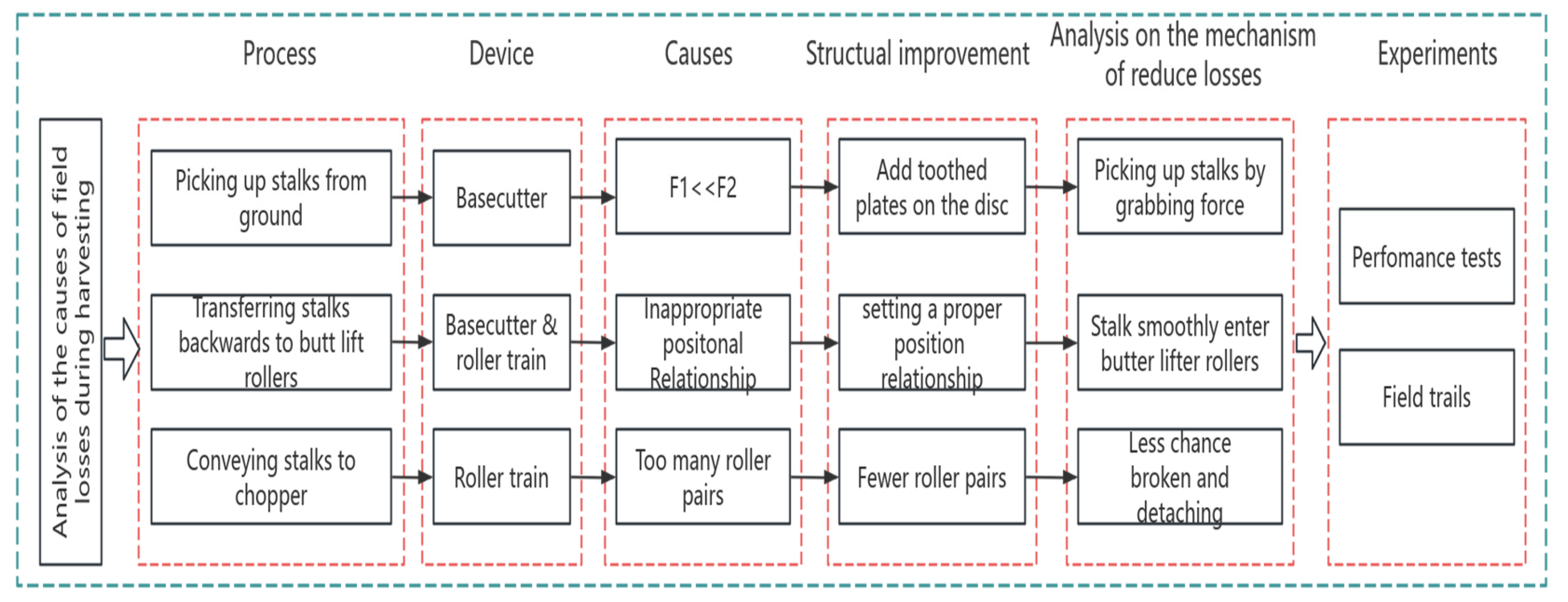
In this study, the authors observed that losses occur primarily during three key operational stages: (1) stalk pickup by the basecutter, (2) stalk transfer to the butt roller train, and (3) stalk conveyance to the chopper. They analyzed the underlying causes of these losses and proposed targeted solutions. Figure 2 illustrates a schematic flow diagram of the developmental framework for the field loss reduction technology investigated in this study.

2.1. Experiment on the Friction Coefficient Between Sugarcane and Soil as Well as Between Sugarcane and Steel Plates

In analyzing the causes of field loss during harvesting, the static friction coefficient (SFC) between sugarcane and soil, as well as between sugarcane and steel plates, was considered. While some studies reported SFC values for sugarcane and steel plates [19], no prior studies were found regarding the SFC between sugarcane and soil. To ensure data comparability, we measured the SFC for both sugarcane–soil and sugarcane–steel interactions in this study.
The sugarcane variety used was Yuetang 55, and the soil type was red soil. Both were obtained from the Suixi Test Station in China on 16 July 2025. The field area measured 10 hectares, with row spacing of 1.2 m. The steel plates used in the experiment were made of Q235A grade steel.
Sugarcane stem samples were prepared by cutting them into 80 mm billets. Two sections were bonded together to form a single sample. A total of six samples was prepared: three with leaves attached (WL) and three de-leafed (DL). The leaves were affixed to the stems using adhesive.
Based on the relevant literature [20], soil samples with three moisture contents (MCs)—5%, 10%, and 15%—were prepared to test the sugarcane–soil SFC. Different moisture levels were achieved by adding water to dry soil. The drying process involved placing soil cakes in a DHG-9073A electric forced air drying oven at 50 °C. The samples were weighed hourly using an RS232 electronic scale (resolution: 0.1 g). Drying was considered complete when the weight difference between two consecutive measurements fell below 1%.
The required water mass for each target MC was calculated based on the dry soil weight. After adding an appropriate amount of water, the soil was thoroughly mixed and finely broken up to ensure a flat surface for testing.
The static friction coefficient (SFC) was determined using the inclined plate method. The samples were placed in both horizontal (H) and vertical (V) orientations on the inclined plate as illustrated in Figure 3.
Soil was filled into a plastic tray, and its surface was leveled into a flat plane. The tray was then fixed onto an inclined plate. The inclination angle of the plate relative to the horizontal plane was gradually increased, and the critical angle (ψ) at which the sample began to slide downward was recorded. The static friction coefficient (SFC) was calculated as SFC = tan(ψ).
The following definitions were established:
f1: SFC between the stalk and steel.
f2: SFC between the stalk and soil.
f1vdl: SFC between the stalk (de-leafed) and steel in the vertical orientation.
f1hdl: SFC between the stalk (de-leafed) and steel in the horizontal orientation.
f2vwl: SFC between the stalk (with leaf) and soil in the vertical orientation.
f2hwl: SFC between the stalk (with leaf) and soil in the horizontal orientation.

2.2. Measurement of Lodged Sugarcane and Definition of Lodging Angle

2.2.1. Measurement of the Spatial Posture of Lodged Sugarcane

Using the method for measuring the spatial posture of lodged canes developed by an author of this article in his previous research [4], the spatial posture of lodged sugarcane in the experimental field was measured.
(1) Testing equipment
The testing equipment included a T-square with a measurement length of 1 m; a tape measure with a length of 3 m; and a flexible ruler with a length of 3 m.
(2) Coordinate system of sugarcane
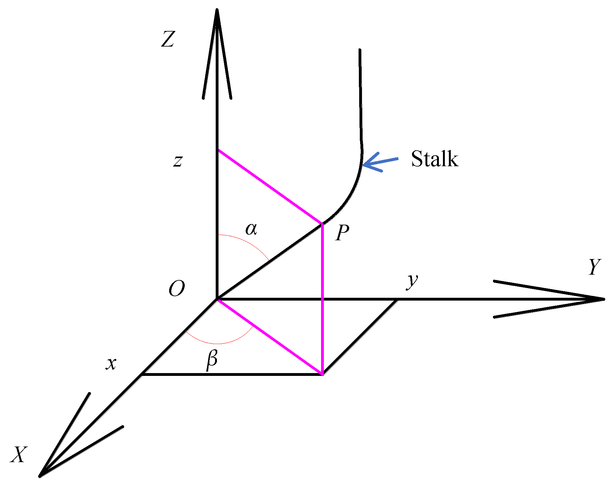
The intersection point of the sugarcane base and the ground was designated as the coordinate origin O. The X-axis was aligned with the sugarcane ridge, while the Y-axis was set perpendicular to the ridge along the ground plane. The Z-axis was defined as the direction orthogonal to the XOY plane, oriented upward. The positive X- and Y-axes were oriented such that the sugarcane lay within the first quadrant of the XOY coordinate system. This configuration facilitated the measurement of coordinate values for points along the sugarcane.
(3) Selection and measurement of key points for lodged canes
Key points were selected to describe the spatial posture of the sugarcane. These points included point O, the two endpoints of a straight section and the two endpoints and three middle points of a curved section. For sugarcane stalks with multiple curved sections, the key points were chosen separately for each curve.

2.2.2. Definition of Lodging Angle (α)

The literature provides definitions of the lodging angle and the lateral deflection angle of the straight lodged cane. There is no definition for the lodging angle or lateral deflection angle of curved stalks. The base of a lodged cane is generally straight. In this study, the angle formed by this straight line segment and the z-axis was defined as the lodging angle, while the angle between this segment and the x-axis was defined as lateral deflection angle, as shown in Figure 4.

2.3. Analysis of the Causes of High Field Loss Ratio During Lodged Sugarcane Harvesting

2.3.1. Understanding Sugarcane Chopper Harvester and Its Field Losses During Harvesting

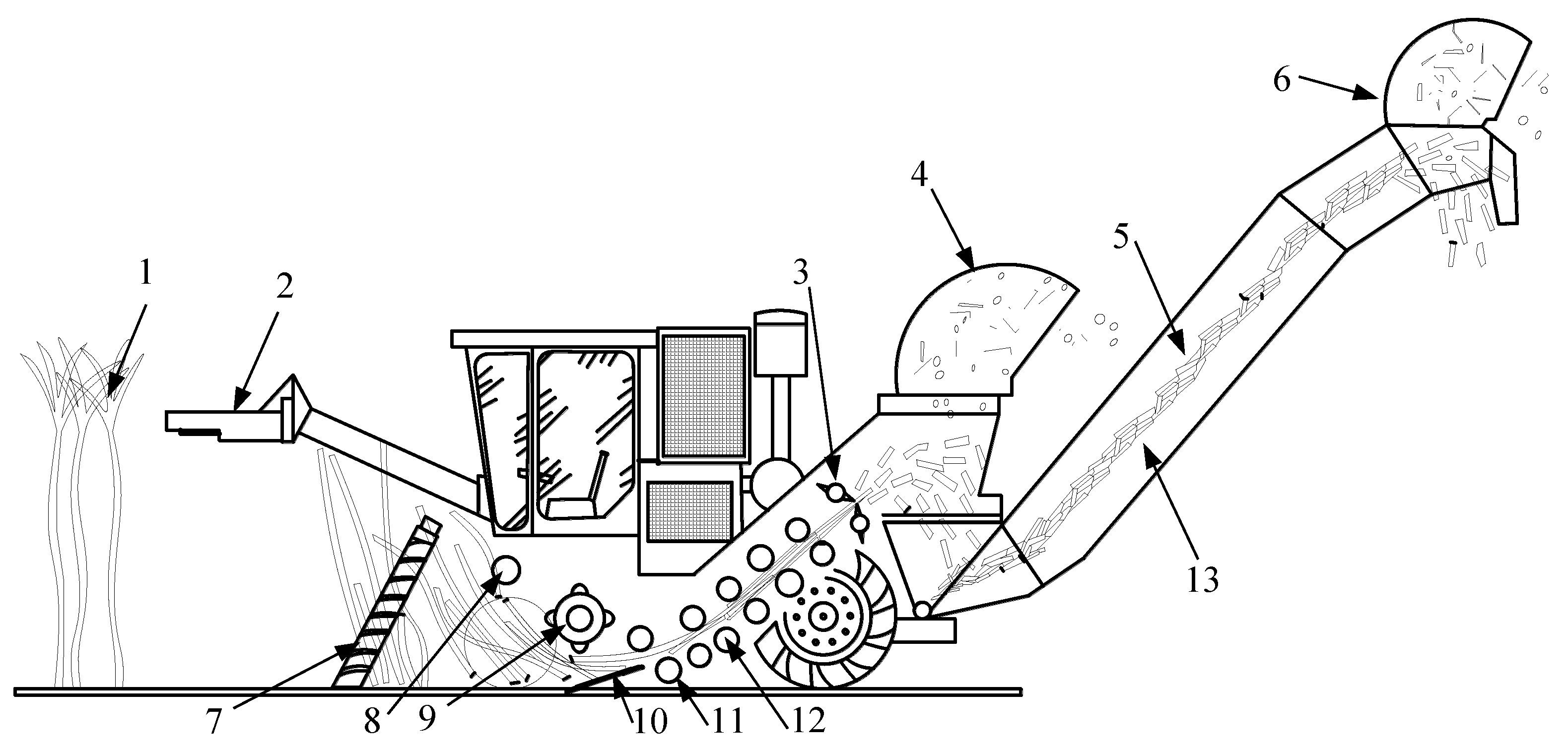
Understanding the harvester’s operational workflow is essential for analyzing the causes of field losses during harvesting. Typically, a sugarcane chopper harvester’s process follows the sequence illustrated in Figure 5 [10].
As shown in Figure 5, the harvesting process begins with the topper cutting off the top of the sugarcane, the dividers separating the adjacent rows of sugarcane, and the knockdown roller pushing over the sugarcane stalks, after which the basecutter cuts them near ground level. Subsequently, the basecutter transfers the stalks backward to the butt lifter roller, from which they are fed into the chopper via a series of rollers (roller train). Finally, the chopped billets are ejected into the extractor for trash removal, and the cleaned billets are transported to the haul vehicle by the elevator.
According to the JB/T 6275-2019 Sugarcane Combine Harvester standard [21], field losses in sugarcane harvesting comprise two primary types: lost losses and stubble losses. Lost losses refer to sugarcane stems and billets that remain in the field after harvest, while stubble losses are defined as stubble segments exceeding 30 mm in height. Additionally, juice losses occur during the chopping of stalks into billets, typically ranging from 2 to 5 tonnes per hectare [10]. Theoretically, if the basecutter blades were able to cut stalks below ground level, stubble losses could be eliminated entirely. Consequently, this study focused on strategies to minimize lost losses.
The elevated field loss ratio observed during the harvesting of lodged sugarcane is attributed to three key factors: (1) severely lodged stalks are challenging for the basecutter to retrieve, (2) some stalks are not effectively conveyed to the butt lifter roller, and (3) bent stalks tend to break and detach from the roller train.

2.3.2. Harvest Losses During Sugarcane Pickup by Basecutter

(1) Mechanism of sugarcane pickup from the ground by basecutter
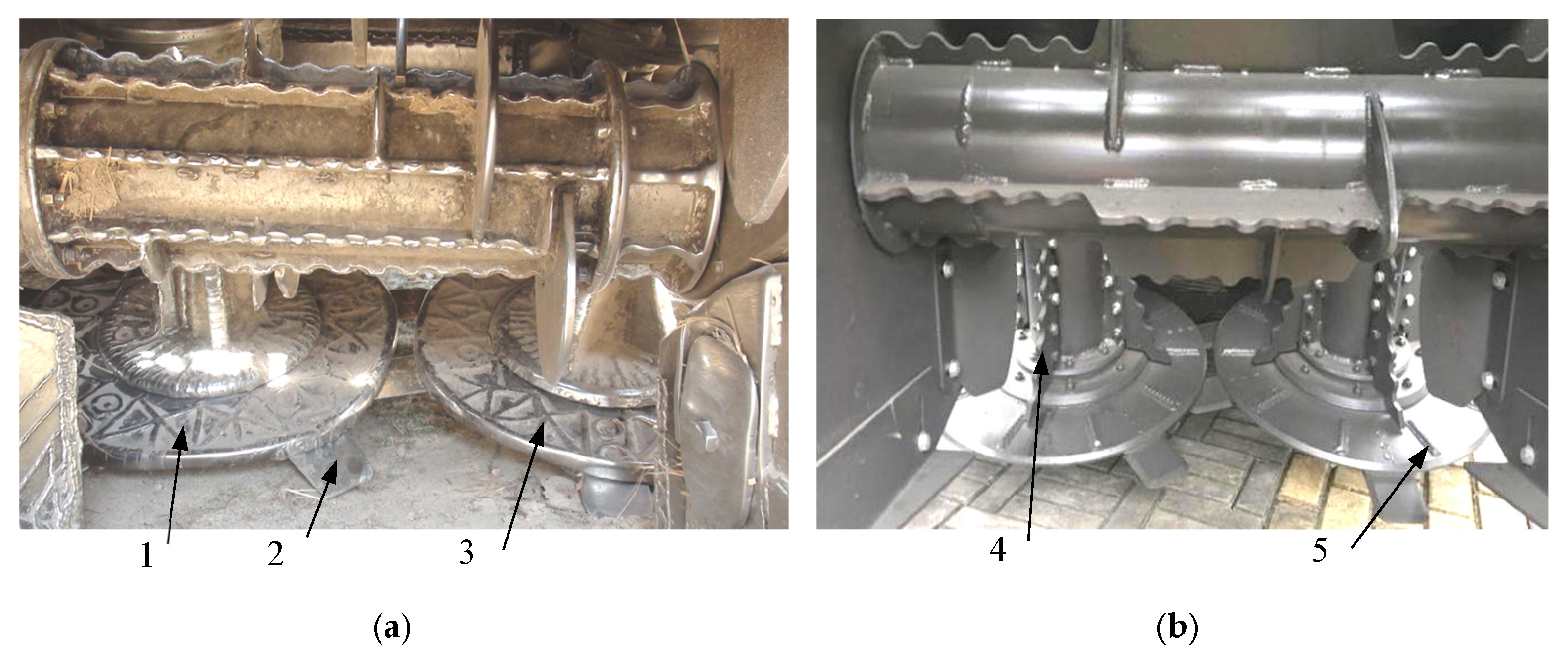
The basecutter is responsible for cutting sugarcane stalks, collecting them from the ground, and transferring the cut canes to the butt lifter roller [10]. Typically, it consisted of a double-disc cutting system, with each disc equipped with from three to six blades [22,23] (Figure 6). Figure 6b displays a basecutter of an AC 60 sugarcane harvester photographed by the authors of this study.
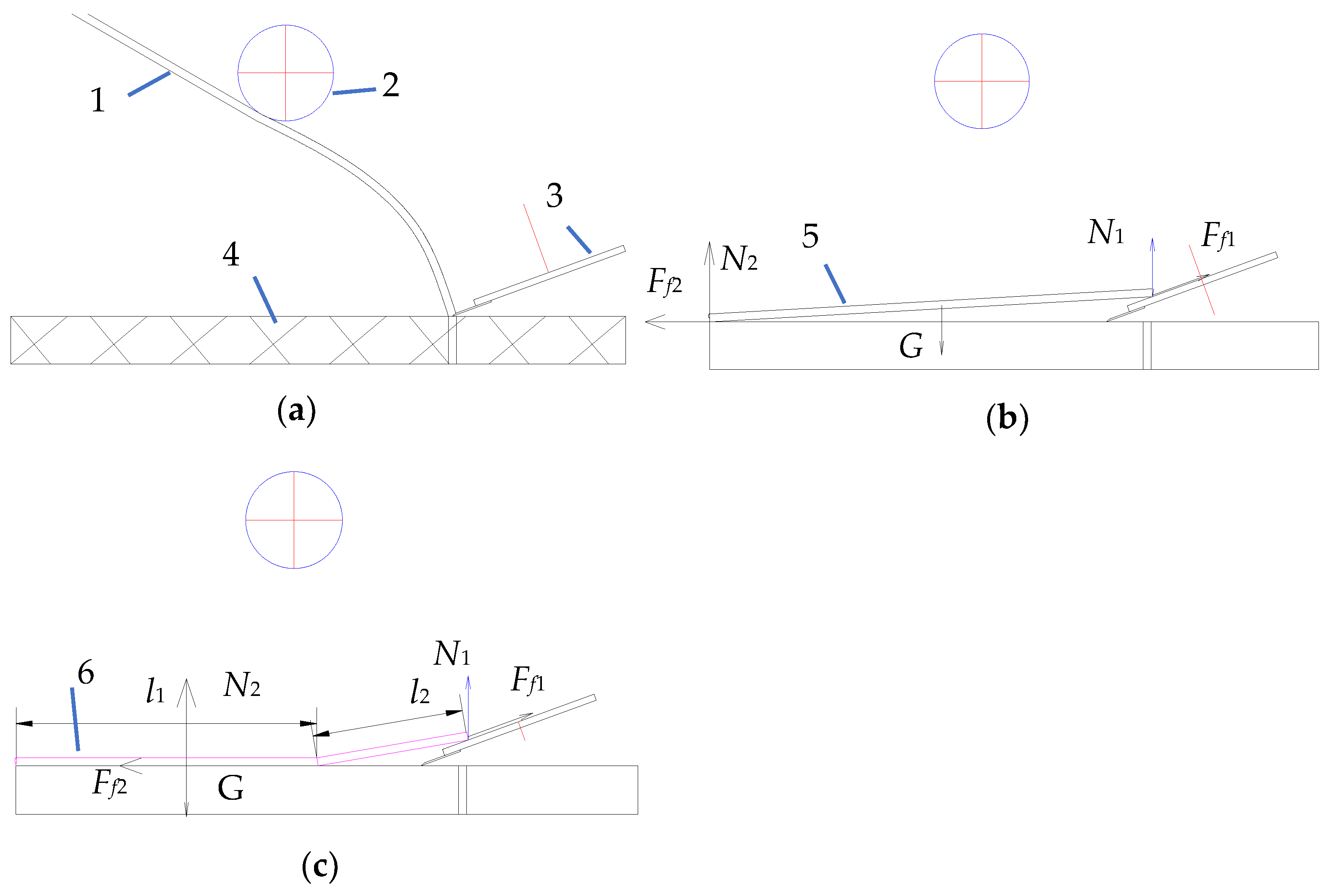
During harvesting, the blades cut the canes close to or below the ground surface, as illustrated in Figure 7a. Subsequently, the stalks are picked up and transferred backward by the upper surface of the disc and the paddles mounted on its spindle. The disc picks up and transfers the sugarcane through friction between its surface and the stalks. Figure 7b,c presents the force analysis of sugarcane being picked up and transferred by the disc. As shown in Figure 7a, the sugarcane stalk was cut at its base. Once severed, the stalk fell downward. During its descent, the harvester continued moving forward, causing the basecutter’s disc to come into contact with the stalk’s base, as illustrated in Figure 7b,c.
Figure 7b,c depicts a straight stalk and a curved stalk, respectively. G represents the gravitational force acting on the sugarcane, while N1 and N2 denote the reaction forces exerted by the disc and the ground, respectively. Additionally, Ff1 corresponds to the frictional force between the sugarcane and the disc, and Ff2 represents the friction between the sugarcane and the ground. The relationship between these forces is as follows:
G = N1 + N2,
Ff1 = N1 × f1,
Ff2 = N2 × f2,
f1 and f2 are the SFCs of stalk–steel and stalk–soil interactions, respectively. For the disc to successfully pick up and transfer sugarcane, the condition Ff1 > Ff2 has to be satisfied.
As shown in Figure 7b, the base end of the sugarcane rested on the disc, while the top end remained on the ground, with N1 = N2. However, as the SFC test results indicate (showed in the Section Results and Analysis, f1 < f2), if the top surface of disc was smooth, Ff1 < Ff2, according to Equations (1)–(3).
To increase Ff1, most conventional sugarcane harvesters incorporate raised patterns or deformed steel bars on the disc’s flat surface (Figure 7). Toothed paddles were also found to enhance backward transferring efficiency.
(2) Reason for losses during sugarcane pickup
Lodged sugarcane stalks are typically curved, with severely lodged stalks lying almost flat on the ground. When the disc makes contact with the base of the stalk, a significant portion of the stalk remains in contact with the soil, as illustrated in Figure 7c. Consequently, N1 is much smaller than N2. Meanwhile, f1 < f2. Based on Equations (1)–(3), Ff1 is much smaller than Ff2.
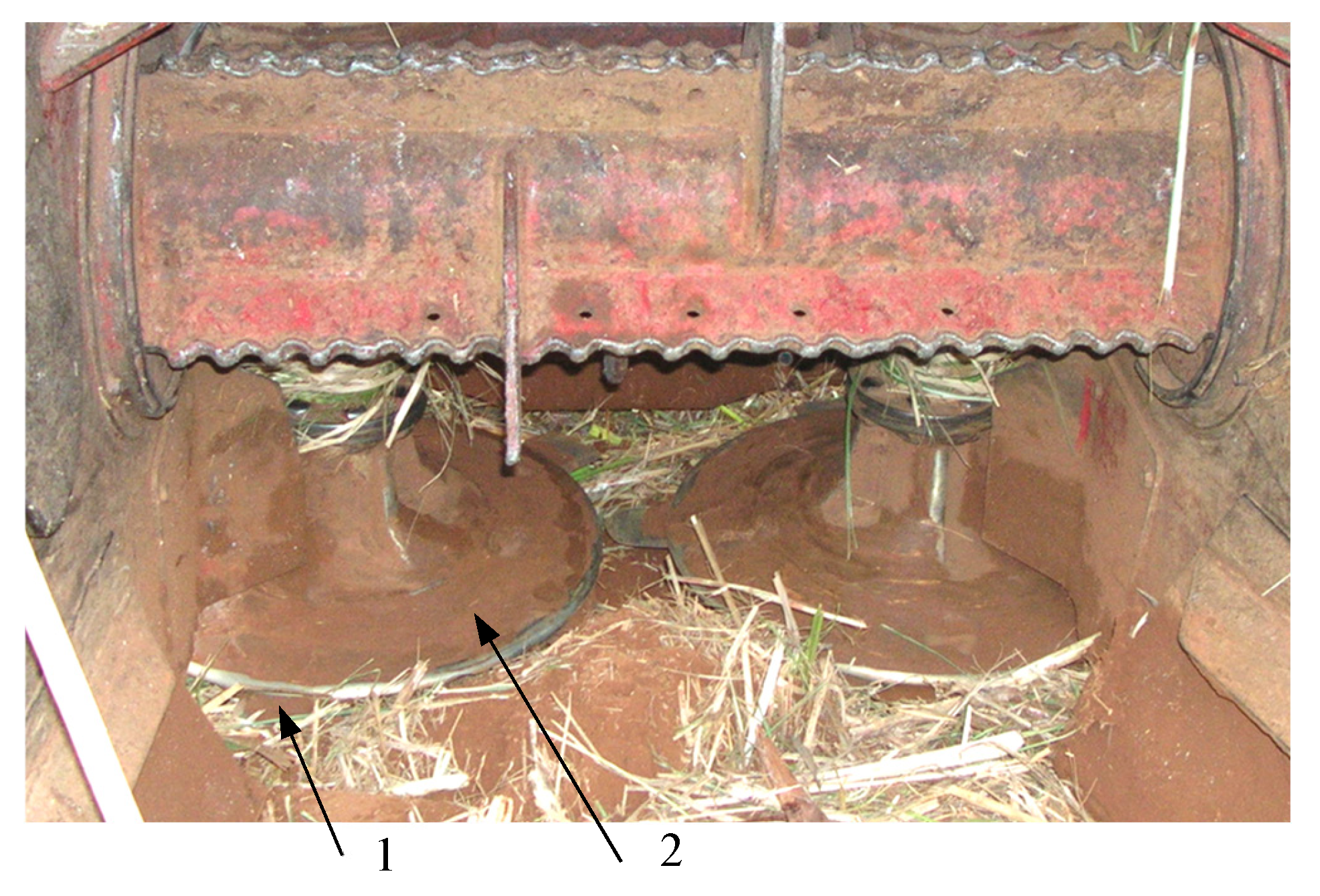
If the raised patterns or deformed steel bars on the disc lack sufficient roughness to ensure Ff1 > Ff2, the disc struggles to lift and convey severely lodged stalks. This issue is particularly pronounced in sticky soil conditions, where soil accumulation on the disc is a problem. When the raised patterns and the steel bars are clogged with sticky soil (Figure 8), their effectiveness is diminished, resulting in f1f2 and Ff1 << Ff2 for severely lodged stalks. This is the primary cause of the high field loss ratio during the harvesting of severely lodged sugarcane. Figure 8 shows the basecutter of a CASE 7000 sugarcane harvester photographed by the authors of this study.

2.3.3. Harvest Loss During the Transfer of Canes Backwards to Butt Lift Roller by Basecutter

(1) Mechanism of transferring canes backwards to butt lift roller by basecutter
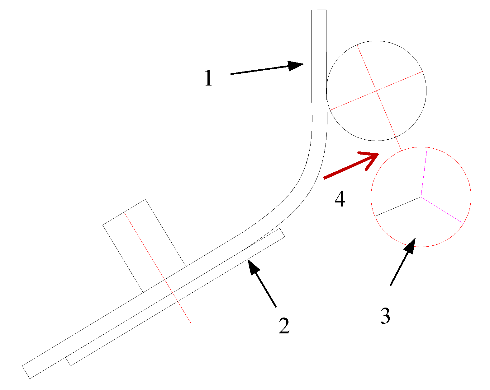
The cut canes are supposed to enter the gap (channel) between the upper and lower butt lift rollers. If they fail to do so, the canes remain in the field, resulting in harvest losses. Due to their naturally bent or curved shape, some stalks have difficulty entering the roller gap, as illustrated in Figure 9. Additionally, an improper positional relationship between the basecutter disc and the butt lift rollers occasionally prevents even straight canes from entering the channel between the rollers. Therefore, establishing the correct geometric alignment between the basecutter and the butt lift rollers is crucial to ensure smooth cane entry into the channel.
(2) Analysis of position relationship between basecutter and butt lift rollers
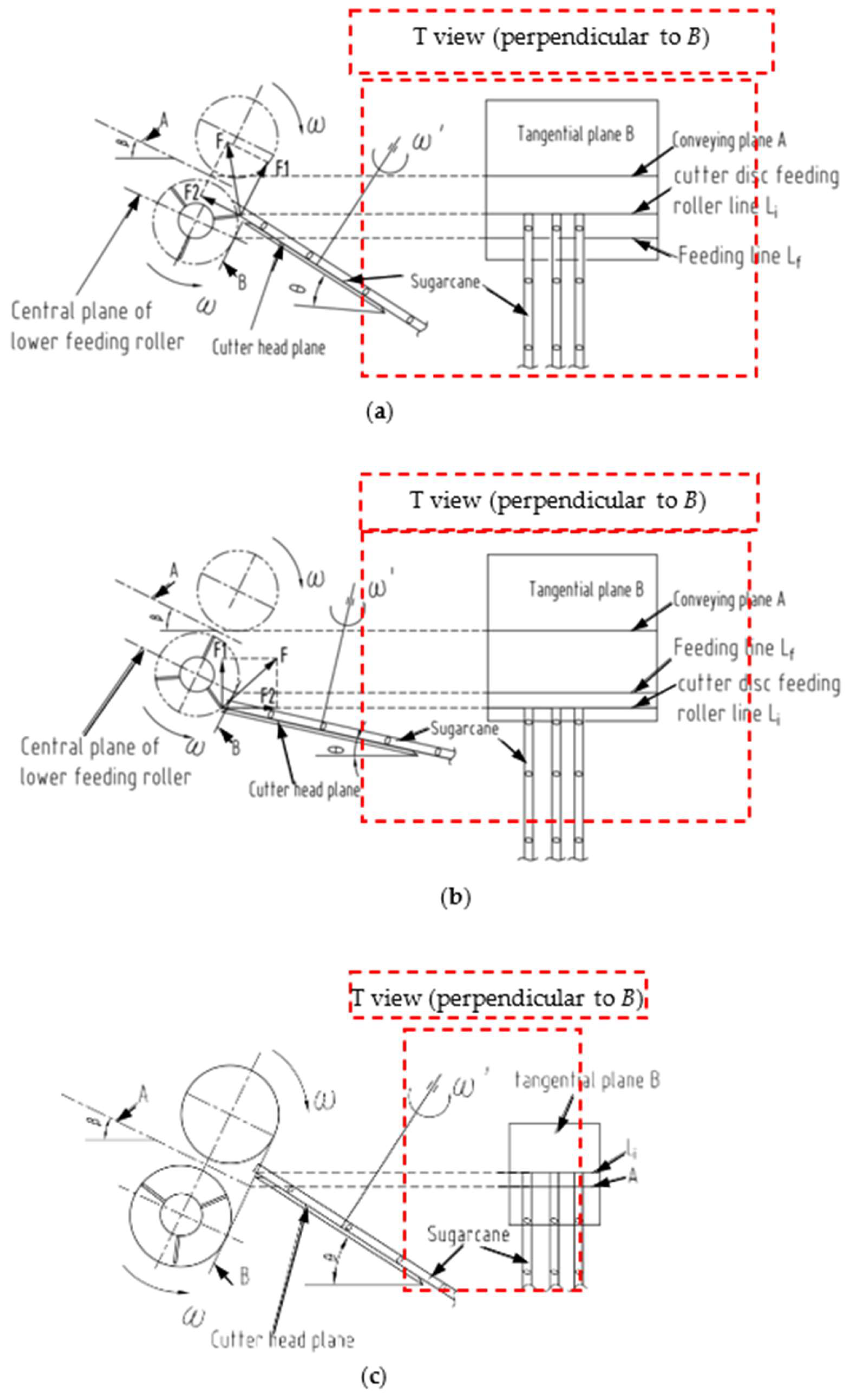
To analyze the positional relationship, several key definitions were established, as illustrated in Figure 10.
Conveying Plane (A): The symmetrical plane between the upper and lower rollers was designated as the conveying plane and labeled A.
Outer Cylindrical Surface: When the lower butt lift roller rotated, the outer edges of its blades formed a cylindrical surface, referred to as the outer cylindrical surface.
Tangential Plane (B): The plane perpendicular to the conveying plane (A) and tangent to the outer cylindrical surface was defined as the tangential plane and labeled B.
Feeding Line (Lf): The line of intersection between the central plane of the lower butt lift roller and the tangential plane (B) was termed the feeding line and denoted Lf.
Cutter Disc Feeding Roller Line (Li): The intersection line between the top surface of the cutter disc and the tangential plane (B) was named the cutter disc feeding roller line and labeled Li.
Position relationship between Li and Lf. In Figure 10a,b, the force F applied to the sugarcane stalk by the blade of the lower butt lift roller is resolved into two components: F1 and F2. The vertical component F1 lifts the stalks upward.
When Li was positioned above Lf (Figure 10a), the horizontal component F2 conveys the stalks toward the butt lift rollers. Conversely, when Li is below Lf (Figure 10b), F2 acts to push the stalks away from the rollers. Consequently, successful feeding of sugarcane into the rollers only occurs when Li is maintained above Lf.
Position relationship between Li and A. When Li is positioned above plane A (Figure 10c), the blades of the lower butt lift roller fail to engage properly with the sugarcane stalks. This ineffective contact prevents successful feeding of the stalks into the roller mechanism. The analysis demonstrated that proper feeding requires Li to be maintained below plane A.

2.3.4. Harvest Losses During Sugarcane Conveyance in the Roller Train

(1) Structure of roller train
Modern sugarcane chopper harvesters typically feature multiple pairs of rollers positioned between the basecutter and the chopper, collectively referred to as the roller train. For instance, the CASE 8000 harvester is equipped with 5.5 pairs of rollers in its roller train, as illustrated in Figure 5.
(2) Structure of butt lift rollers and their sugarcane conveyance mechanism
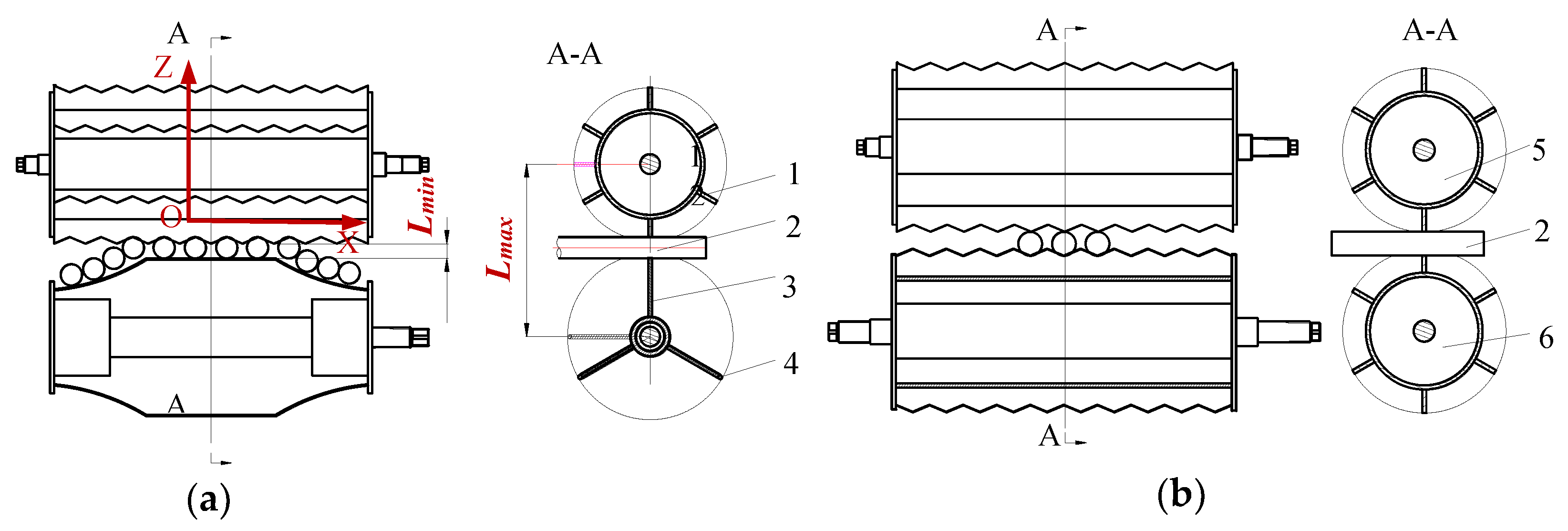
Structure of butt lift rollers. The butt lift rollers are responsible for receiving sugarcane stalks from the basecutter and transporting them to the feed rollers. The system consists of an upper and a lower roller (Figure 11a). The upper butt lift roller was designed as a floating roller, allowing for it to adjust vertically based on the volume of sugarcane passing through. To enhance stalk-gripping efficiency, the lower butt lift roller has rebar rods welded along the outer edges of each blade.
Conveyance Mechanism of the Butt Lift Rollers. As illustrated in Figure 11a, the upper roller consists of six blades, while the lower roller has three. Both the rollers rotate at the same angular velocity, causing the clearance between their blade tips to vary cyclically from the minimum (Lmin) to the maximum (Lmax).
The clearance reaches its maximum when the blades of both rollers are perpendicular to the XOZ plane. At this position, the lower roller blade lifts the cane butt and feeds it into the gap between the upper and lower rollers. Conversely, the clearance minimizes when the blades align parallel to the XOZ plane, causing the upper and lower blades to push the cane backward.
As the clearance transitions from Lmax to Lmin the rollers clamp the stalks and propel them forward toward the subsequent roller pairs.
(3) Structure of feed rollers and their sugarcane conveyance mechanism
The feed rollers are responsible for transporting sugarcane stalks from the butt lift rollers to the chopper. Additionally, they help stabilize the stalks’ moving speed and provided support, ensuring uniform billet length from the chopper.
As shown in Figure 11b, the feed rollers consist of an upper and a lower roller, each equipped with six uniformly spaced wavy blades. The minimum clearance between the crest of one blade and the trough of the opposing blade match the average diameter of sugarcane stalks. The upper roller was designed as a floating roller, using its own weight to press the stalks firmly against the lower roller.
(4) Analysis of curved cane detaching from the roller train
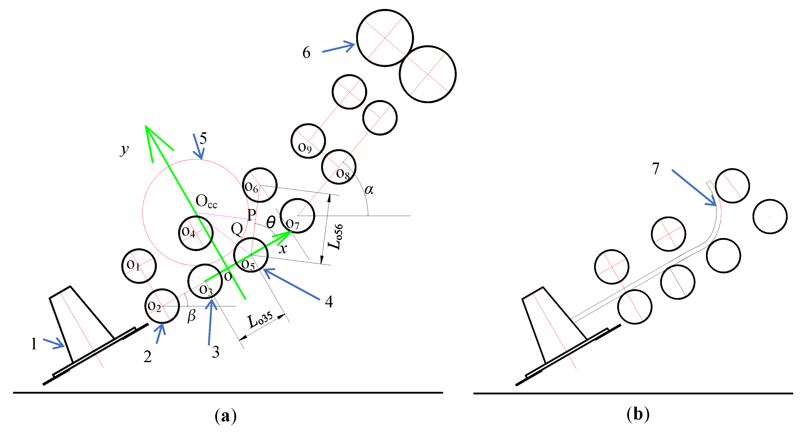
Figure 12a illustrates the common roller train layout of a chopper harvester (i.e., the CASE 7000 chopper harvester). In this figure, om represents the center of the m-th roller, referred to as the om roller. Dom denotes the diameter of the om roller, while Lomn indicates the distance between om and on. The O5 roller serves as a transitional roller.
The angle between the line o2o3 and the horizontal is labeled α, whereas the angle between o7o8 and the horizontal is denoted as β. Additionally, θ represents the angle between o2o3 and line o5o6.
In Figure 12a, since β > α, the distance Lo46 is greater than any other Lomn between the adjacent rollers (m and n). This creates an opportunity for bent stalks to detach from the roller train.
Figure 12a also depicts a circle Occ, which is simultaneously tangent to rollers o3, o5, and o6. This circle is termed the critical circle. If the radius of a stalk’s curved arc exceeds that of the critical circle (Rcc), the stalk could detach from the gap between the o4 and o6 rollers, as demonstrated in Figure 12b.
In Figure 12a, a Cartesian coordinate system xoy is established. The y-axis is perpendicular to and bisected the line o3o5. The X-axis is o3o5. OccP is perpendicular to and bisects o5o6, and point P is the intersection of o5o6 and line OccP. The straight line OccP is denoted by Equation (4). The distance between points Occ and o5 is expressed by Equation (5). The radius of circle Occ (ROcc) was defined by Equation (6).
y = −tan(90° − θ) × (xLo35/2 − Lo56/(2cos(θ))
LOcco5 = Squre(xo52 + yOcc2)
ROcc = LOcco5Ro5
In Figure 12a, xOcc, yOcc, and xo5 represent the coordinate values of the points Occ and o5.
The geometric parameters of the harvester in Figure 12a are as follows: Lo35 = 330 mm, Lo56 = 439.5 mm, Lo14 = 410 mm, Lo46 = 500 mm, Lo12 = 288 mm, α = 30°, β = 50°, and θ = 53°.
Using Equations (1)–(4), the calculated value of ROcc is 327.2 mm.
(5) Analysis of curved cane clogging in the roller train
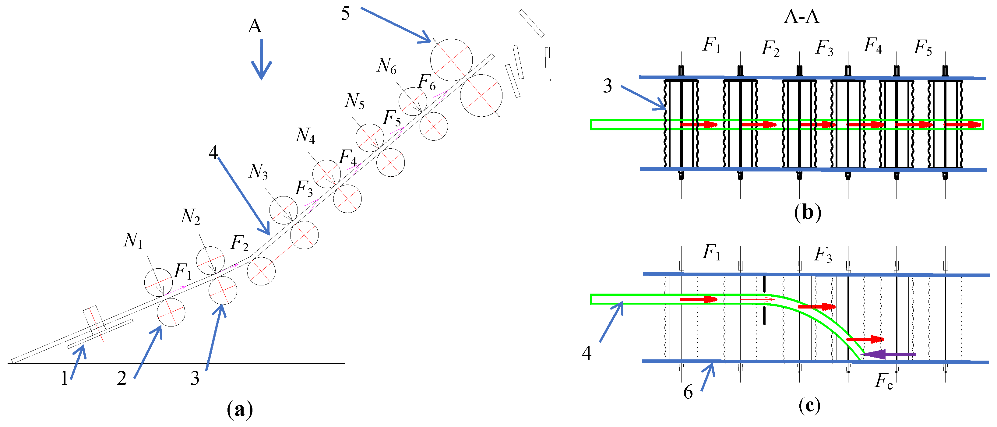
Stalk conveyance is driven by friction between the stalks and the rollers (Figure 13). In this figure, the normal force (N) acting on the cane is generated by the weight of the upper rollers, while F represents the frictional force between the blade of roller and cane. Figure 13b illustrates the forces acting on a straight cane stalk, while Figure 13c shows the forces on a curved cane. When one end of the bent stalk is pressed against the side wall of the channel, the side wall exerts a force (Fc, in Figure 13c) that hinders the movement of the stalk.

2.4. Performance Enhancement of Chopper Harvesters: Structural Improvements and Field Loss Mitigation Mechanisms

2.4.1. Basecutter Structural Modifications and Stalk Pickup Mechanism

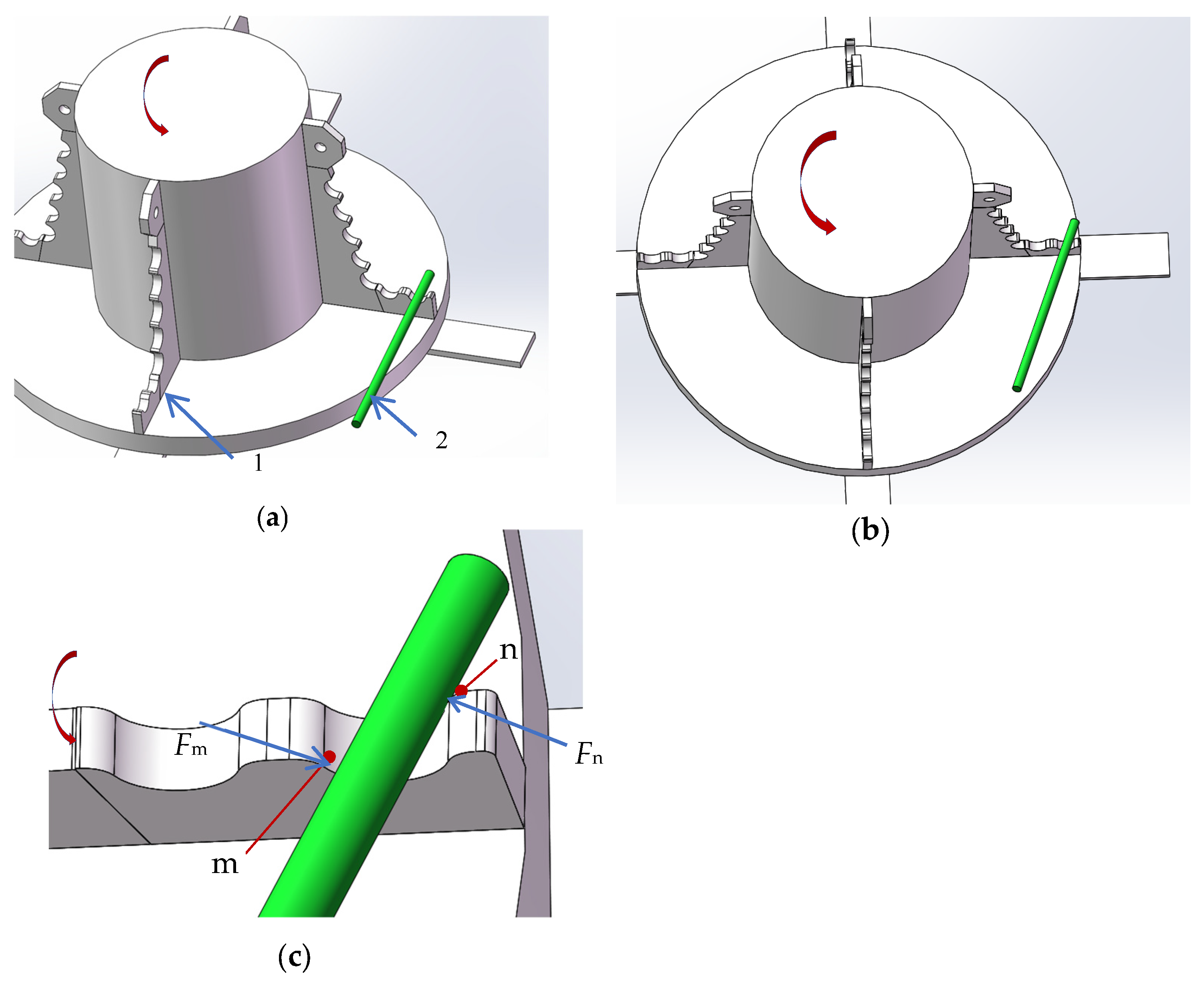
As analyzed in Section 2.2.2, conventional basecutter disc structures struggle to effectively pick up and convey severely lodged sugarcane stalks, particularly in sticky soil conditions. To address this limitation, this study proposed adding small-toothed plates on the upper surface of the disc to enhance lodged stalk recovery. The design and operating mechanism of these toothed plates are illustrated in Figure 14.
During operation, the stalk butt makes contact with a toothed plate after being cut. When the stalk is perpendicular to the plate (Figure 14a), it settles into the groove between the teeth. With the disc rotating, the angular relationship between the stalk and plate changes (Figure 14b), causing the stalk to be gripped by both sides of the groove (Figure 14c). Forces Fm and Fn act backward on the stalk to maintain engagement.
Given typical sugarcane stalk diameters of 20–40 mm [24,25], the groove radius was designed at 22.5 mm to ensure proper stalk containment (exceeding the minimum 20 mm requirement).
Relative to the raised pattern and steel bar configurations shown in Figure 5, the tooth plate’s peak-and-trough design exhibited a superior performance in sticky soil environments.

2.4.2. Position Relationship Between the Disc and Butt Lift Rollers

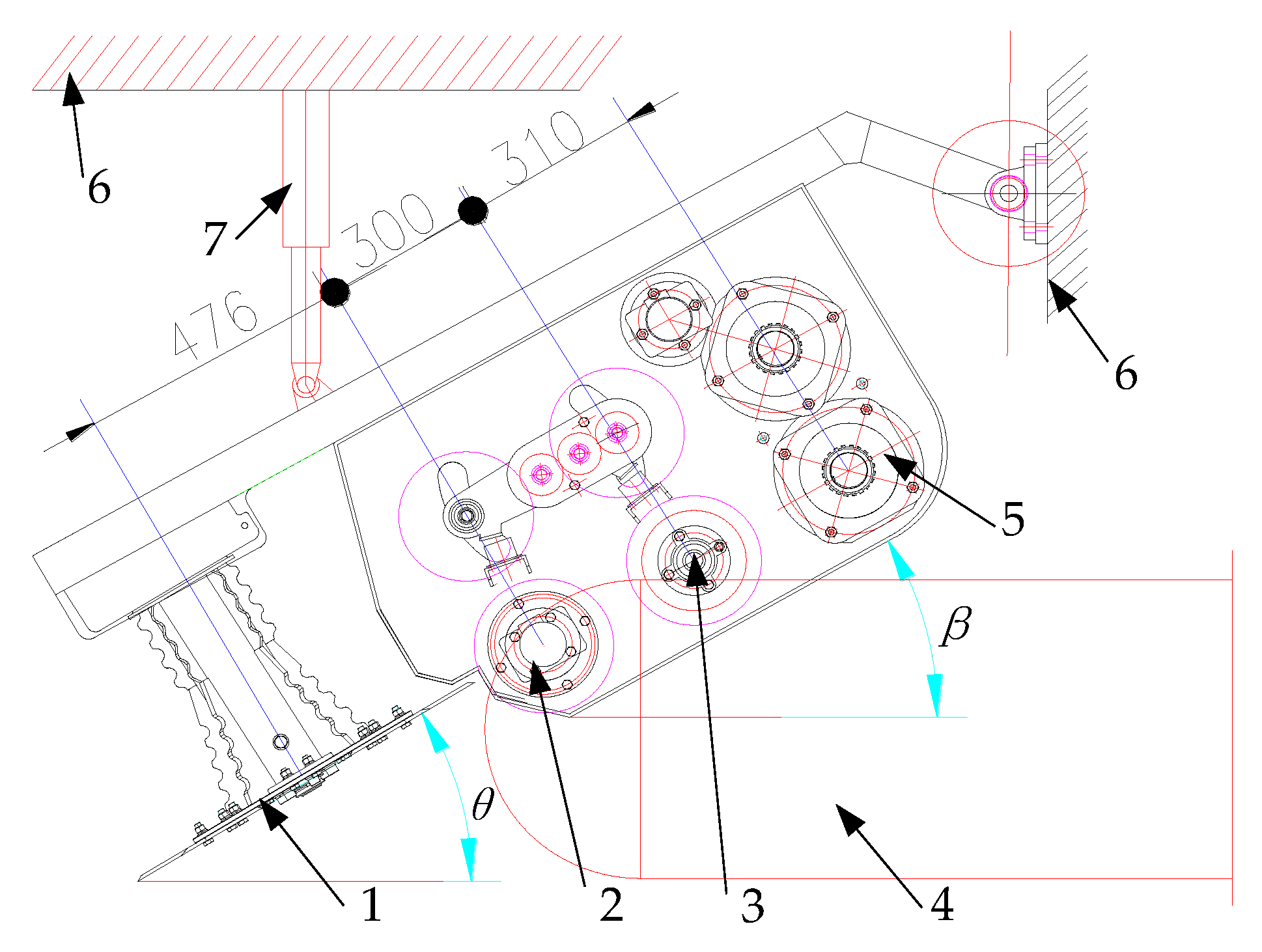
To maintain the fixed positional relationship among Li, Lf, and the conveying plane A, the basecutter, butt lift roller, feed roller, and chopper were mounted on the same frame, as illustrated in Figure 15.
The angles θ and β represent the inclination of the disc and conveying plane A relative to the horizontal plane, respectively. In this study, θ was designed to be 2° greater than β (i.e., θ = β + 2°).
During harvesting, sugarcane was cut at its base, 0–50 mm below the ground level. Previous studies indicated that the disc inclination angle should be maintained within 5–15° [26]. However, to accommodate varying sugarcane row ridge heights across different fields, θ could be adjusted accordingly. A hydraulic cylinder was employed as the adjustment mechanism, as depicted in Figure 15. The hydraulic cylinder enabled real-time angle adjustments during operation.

2.4.3. Structural of Roller Train

Analysis of the Structure Without Roller Train Between Basecutter and Chopper
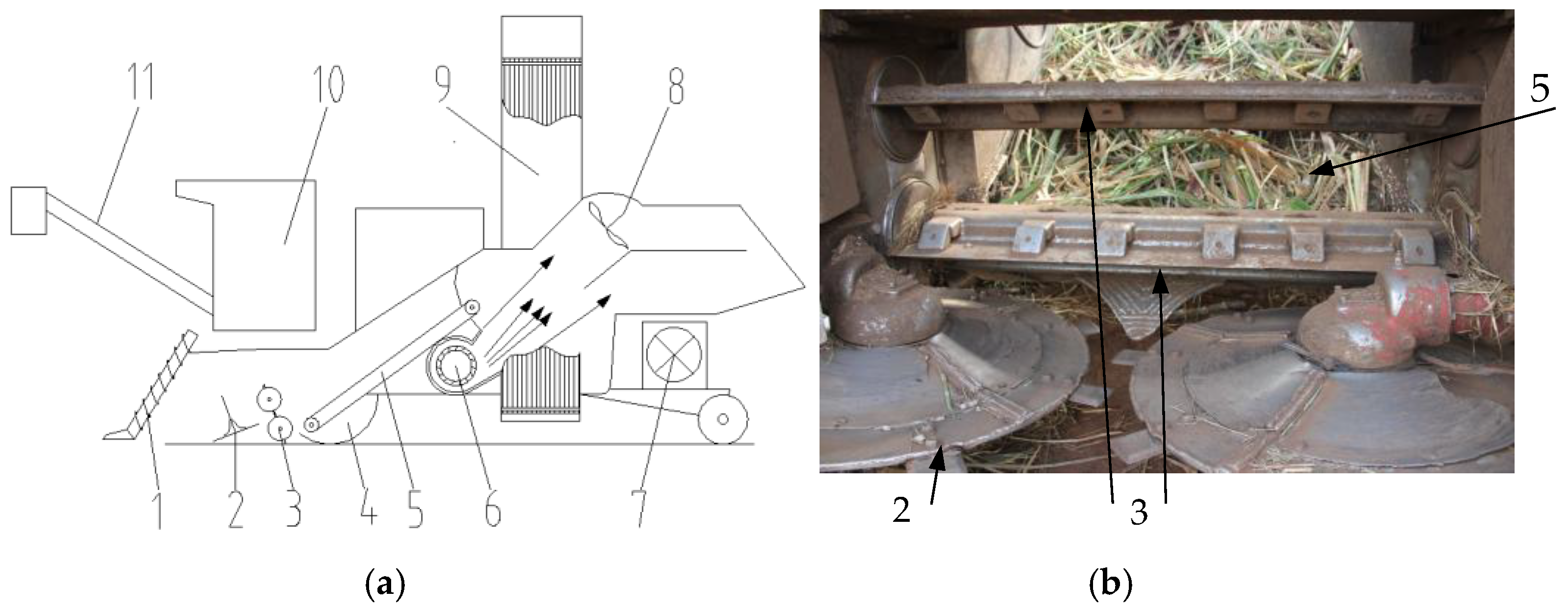
The original CLASS 1400 design featured a sequential arrangement of (1) a basecutter, (2) a chopper, (3) a billet conveying device, and (4) an extractor, without intermediate roller train integration (Figure 16 [11]).
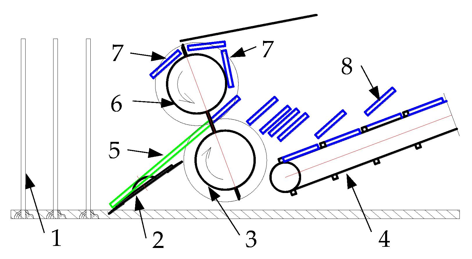
During the harvesting of curved sugarcane stalks, the stalks were directly processed into billets by the chopper without passing through any rollers (Figure 15 and Figure 16). This configuration eliminated the possibility of stalk breakage by the roller train components. However, the chopping process introduced another issue: some billets were frequently recaptured by the blades of the upper chopper roller, leading to significant field losses (Figure 17). The authors observed this phenomenon during field trails at Maui in Hawaii (April 2013).
Structural Improvements of Roller Train
The preceding analysis revealed that an excessive number of rollers between the basecutter and the chopper (Figure 11 and Figure 12) increased the likelihood of curved sugarcane stalks detaching from the roller train or blocking the channel. Conversely, the absence of rollers in this region (Figure 16 and Figure 17) led to a higher probability of billets being recaptured by the blades of the upper chopper roller.
To optimize performance, this study developed an improved roller train configuration consisting of a single pair of butt lift rollers and a single pair of feeding rollers positioned between the basecutter and the chopper (Figure 15).
Compared to the conventional multiple-roller train design (Figure 5), the reduced number of rollers minimized stalk blockage and detachment. Additionally, unlike the roller-free structure (Figure 16 and Figure 17), the new design prevented billet recapture by the chopper blades. These findings suggest that a reduced roller count enhances the chopper harvester performance, a conclusion subsequently validated through further experimentation.

2.5. Development of Improved Sugarcane Harvester

2.5.1. Design of Improved Harvester

Based on the preceding analysis, the research team developed an enhanced sugarcane chopper harvester incorporating the optimized designs of the basecutter, roller train, and billet conveyor systems. The key structural parameters of these components are given as follows.
Basecutter Structural Configuration
The modified basecutter’s dimensional specifications are illustrated in Figure 18.
The disc diameter measured 440 mm, while the blades operated at a maximum rotational radius of 315 mm. Axial spacing between the components was maintained at 540 mm. A vertical clearance of 390 mm was specified between the gearbox’s lower surface and the disc’s upper surface. The small-tooth plate featured a groove radius of 22.5 mm and an overall height of 25 mm.
Structural Dimension of the Roller Train
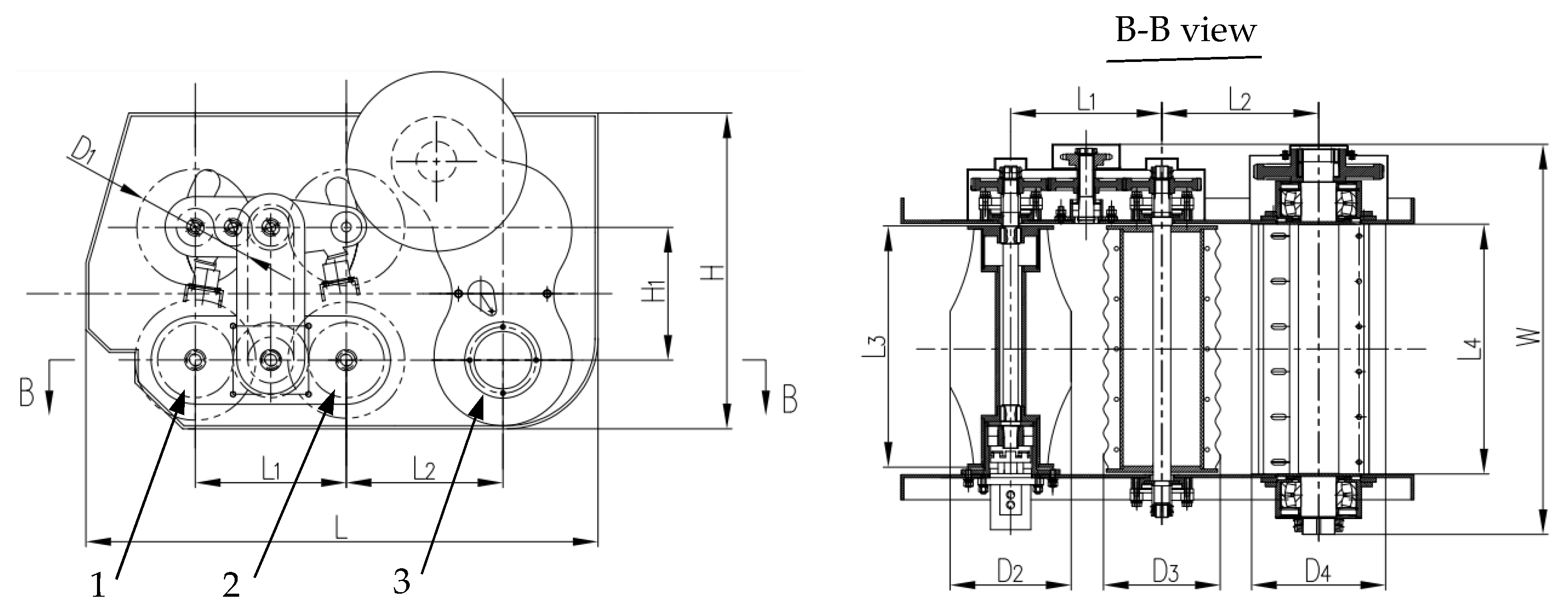
The positional relationship between the basecutter and roller train is illustrated in Figure 15. Figure 19 presents the dimensional specifications of both the roller train and chopper rollers. The key measurements in Figure 19 are as follows: length (L) = 1017 mm, width (W) = 776 mm, total height (H) = 629 mm, H1 = 264.5 mm, L1 = 300 mm, L2 = 310 mm, L3 = 490 mm, L4 = 495 mm, D1 = D3 = 232 mm, D2 = 252 mm, and D4 = 266 mm.
Dimensional Configuration of the Chopper Assembly
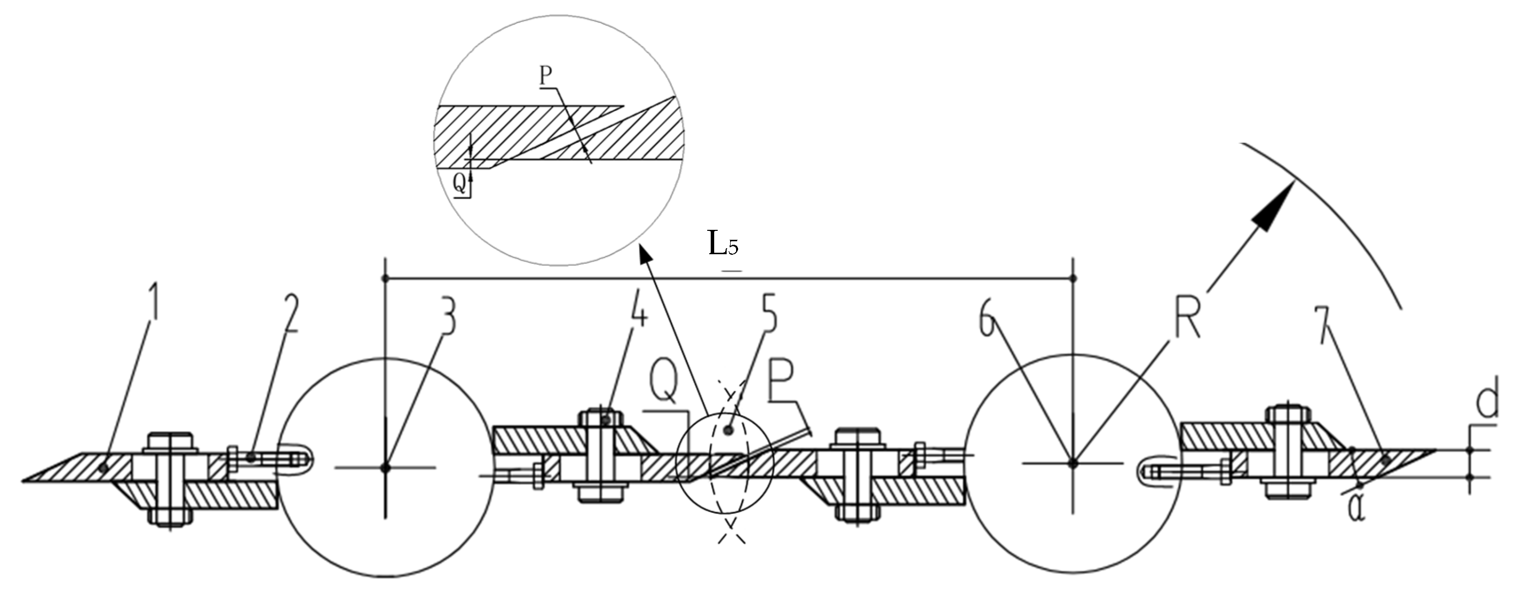
The chopper roller was composed of an upper roller and a lower roller (Figure 19 and Figure 20). The pairing relationship of the upper and lower rollers’ blades is shown in Figure 20 [27].
In this research, the center-to-center distance (L5) between the upper and lower chopping rollers measured 252 mm. Each roller incorporated two symmetrically arranged blades secured using bolt fasteners. The blade geometry was characterized by three critical parameters: gyration radius (R = 133 mm), thickness (d = 10 mm), and edge angle (α = 25°). When the paired blades of the upper and lower rollers were in alignment, inter-blade clearance (Q) was maintained at 6 mm. Additionally, the chopping edges featured a bevel gap (P) of 2 mm.
Structural Dimension of Billet Conveyor System
The billet conveyor was positioned downstream of the chopper rollers, with its complete dimensional specifications detailed in Figure 21. This conveying system operated by transporting billets between uniformly spaced scrapers via continuous chains toward the extractor. The design incorporated several key features: a perforated plate that facilitated soil separation during operation, an effective internal clearance width (W1) of 566 mm, scraper blades with a vertical height (H2) of 160 mm, and consistent inter-scraper spacing (L6) of 450 mm.

2.5.2. Structural Dimensions and Parameters of the Improved Harvester Prototype

A prototype of the improved harvester was developed as a single-row harvester. Designated as the HN4GDL-91 sugarcane harvester, its schematic diagram is presented in Figure 22. The key structural dimensions and design parameters are summarized in Table 1.
Its total weight was 6000 kg, and it was powered by a 97 kW engine. During operation, the maximum ground speed was designed at 5 km/h (1.39 m/s), with a maximum feed capacity of 20 kg/s.

2.6. Performance and Field Test of the Harvester

2.6.1. Experimental Instruments and Equipment

Field performance evaluations were conducted using the HN4GDL-91 sugarcane chopper harvester (Figure 22). The following instruments and tools were employed for data collection and measurements.
(1) Measurement devices:
Electronic balance (precision: ±0.01 kg).
Photoelectric tachometer (DT2234C, measurement range: 2.5–999,999 RPM).
Vernier caliper (resolution: 0.02 mm).
Measuring tape (length: 50 m).
Protractor (angle measurement).
Soil penetrometer (TJSD-750, measurement range: 0–7000 kPa).
Tachometer (EMT260D, measurement range: 1–99,999 rpm).
(2) Supporting equipment:
Digital camera (for photographic documentation).
Agricultural tools (sickle and shovel for field preparation).
A large plastic sheet was placed on the ground to collect the discharged billets, as illustrated in Figure 23.

2.6.2. Field Testing Conditions and Experimental Setup

The field experiments were conducted in January 2018 at the Zhanjiang Test Station of the China Sugarcane Research System. The test site comprised a 100 hectare sugarcane field with the following characteristics.
(1) Soil Properties
Soil type: Red soil. Moisture content: 13–15% at 0–50 mm depth and 18–20% at 50–100 mm depth. Mean soil hardness: 2837 kPa (0–50 mm depth) and 3355 kPa (50–100 mm).
(2) Field Configuration
Dimensions: 330 m (length)×300 m (width). Row spacing: 1.2 m. Total rows: 250.
(3) Crop Status
Severely lodged due to typhoon impact. Sugarcane variety: Yuetang 55. Planting density: 7–9 stalks/m.

2.6.3. Experiment Methods

Field Sampling Methodology
The experimental field contained 250 rows of sugarcane. For testing purposes, 10 rows on one side were reserved for the field test of the harvester. The remaining 240 rows were systematically numbered from 1 to 240. Each row was then subdivided into 33 equal block to establish a sampling grid.
The sampling protocol involved the following steps:
(1) Random selection of both row numbers (1–240) and segment numbers (1–33) for each sample group.
(2) Manual cutting of selected stalks at ground level.
(3) Random allocation of sample groups to experimental treatments.
Performance Evaluation Methodology
To assess the structural improvements’ effectiveness in reducing field losses, key performance indicators were selected in accordance with JB/T 6275-2019 Sugarcane Combine Harvester standard [21], including the following:
(1) Field loss ratio (Sz)
The field loss ratio (Sz, %) was defined as the percentage of total sugarcane stem mass remaining in the field (Wloss) after harvest relative to the harvestable stem mass (Wq) in each test plot. The calculation is given as follows:
S z = W l o s s W q × 100
(2) Feed quantity (Qw)
The feed quantity (Qw, kg/s) was defined as the total mass of sugarcane processed by the harvester per unit time. This parameter was calculated as follows:
Q w = W s + W p a t
where Ws is the total mass of harvested material collected from the harvester’s elevator output in the test plot, kg; Wpa is the processed material obtained from the extractor discharge in the test plot, kg; and t is the total harvesting time recorded for the plot.
Billet Qualification Ratio (Cdh)
The billet qualification ratio (Cdh, %) was defined as the percentage of qualified billet mass (Cdh, kg) relative to the total billet mass (Wdz, kg) collected from the harvester during each test. The qualification criterion followed the JB/T 6275-2019 Sugarcane Combine Harvester standard [21]. The ratio was calculated as follows:
C d h = W d h W d z × 100
Performance Test Methods
(1) Test methods
In the field, sugarcane often grows in clusters due to tillering. Consequently, the harvester needed to be capable of harvesting clustered sugarcane. To simulate severely lodged sugarcane clumps, multiple stalks were placed closely together, with their bases oriented toward the harvester. These stalks were treated as a single group. Three such groups were sequentially arranged in the field as illustrated in Figure 24. Since the stalks entered the roller train base first, all the groups were harvested in the direction from their bases to their tops during the tests.
Test factors and experimental design. The rotational speed of the lift/feed rollers was positively correlated with the moving speed of stalks in the roller train. The moving speed affected the feed quantity (Qw). The ground speed also affected the feed quantity (Qw). The rotational speed of the chopper determined its cutting speed and affected the quality of cutting billets (Cdh). Therefore, the test factors included the chopper’s rotational speed, the number of sugarcane stalks per group, the rotational speed of the butt lift/feed rollers, and the harvester’s ground speed. Prior to the experiment, preliminary field tests were performed to determine the operational ranges of all the conditions under which the harvester functioned smoothly. Based on those results, the specific level values for each factor were established. Table 2 presents the factors and their respective levels. An L27(313) orthogonal array was selected to conduct the tests. Each treatment was replicated three times.
(2) Method for determination of Optimal Factor Combination
The comprehensive balance method was employed to identify the optimal factor combination for improving the harvester performance. The optimization process followed these methodological steps:
Performance Priority Establishment. Based on the study objectives, the performance indicators were prioritized as follows: primary, field loss ratio (Sz); secondary, feed quantity (Qw); and tertiary, billet qualification ratio (Cdh).
Factor Selection Criteria. Statistical analysis revealed that factors showing significant effects (p < 0.05) on Sz and Qw received priority consideration. Interaction effects between factors were incorporated into the optimization model.
Optimization Procedure. The comprehensive balance method integrated the range analysis results from orthogonal testing, the variance decomposition outcomes, and practical operational constraints.
Field Test Methods of the Harvester
During the field test, the harvester reaped lodged sugarcane in the field. In accordance with the sugarcane harvester test standard [21], the test area was divided into a stabilization zone, a measurement zone, and a parking zone, with lengths of 20 m, 10 m, and 10 m, respectively. The harvester traveling in the direction the lodged stalks fell over.
Billets collected from the plastic sheet corresponding to the test area were used as samples (Figure 24). The harvester’s ground speed, chopper rotational speed, and butt lift/feed roller rotational speed were set according to the optimized parameter combination obtained from prior performance tests. Each treatment was replicated three times. The field trials were conducted by Guangdong Provincial Agricultural Machinery Appraisal Station staff.

3. Results and Analysis

3.1. The Results and Analysis of the SFC Tests

The results of the static friction coefficient (SFC) tests are presented in Table 3. The SFC values between the sugarcane stalks (de-leafed) and soil ranged from 0.59 to 0.84 in the vertical direction and 0.5 to 0.8 in the horizontal direction. For the stalks with leaves, the SFC values in relation to soil were 0.50–0.83 (vertical) and 0.64–0.9 (horizontal). Additionally, the SFC between the de-leafed stalks and steel was 0.48, while for the leafed stalks, it ranged from 0.4 to 0.48.
This study investigated the ability of the basecutter to pick up sugarcane. What is needed to be known are the SFC between the sugarcane stalks and soil and the SFC between the stalks and the steel plates. The base of sugarcane stalks in fields sometimes have leaves, and sometimes they do not. Therefore, the results of the experiments in Table 3 could be summarized as follows: the SFC between the stalks and steel was 0.4–0.48, and it was 0.5–0.9 between the stalks and soil.
In another study [19], the SFC between sugarcane stalks (de-leafed) and steel was 0.377–0.515. Overall, the SFC between the sugarcane stalks and steel is lower than that between the stalks and soil, that is, f1 < f2.

3.2. Sugarcane Field Lodging Severity

(1) Dimensions of sugarcane stalk
Sample size: 125.
Diameter (Mean, standard deviation): 23.45, 2.54 mm (at base); 24.48, 3.08 mm (at middle); and 20.94, 2.91 mm (at top).
Length: (Mean, standard deviation): 2.26, 0.276 m.
(2) Sugarcane Field Lodging Severity
Sample size: 2500. Sampling method: Randomly select one 2 m long block per row, with 10 sugarcane stalks in each block.
Lodging percentage in field: slight lodging (0–30°), 15.4%; moderate lodging (30–60°), 47.2%; and severe lodging (60–90°), 37.4%.
Bending status of lodged canes: 73.6% lodged canes had one curved section (Figure 25a), and 26.4% lodged canes had two curved sections (Figure 25b).

3.3. Results and Analysis of the Performance Test

The test results are presented in Table 4, where the values represent the averages of three repeated treatments. Variance analysis of the test results is provided in Table 5. The statistical analysis revealed the following key findings: Factor A had an extremely significant effect (p < 0.01) on indicator Cdh. Factor B showed significant effects (p < 0.05) on indicators Sz and Qw. The interaction effects A×D and B×D exhibited extremely significant influences (p < 0.01) on all the three indicators (Sz, Qw, and Cdh).
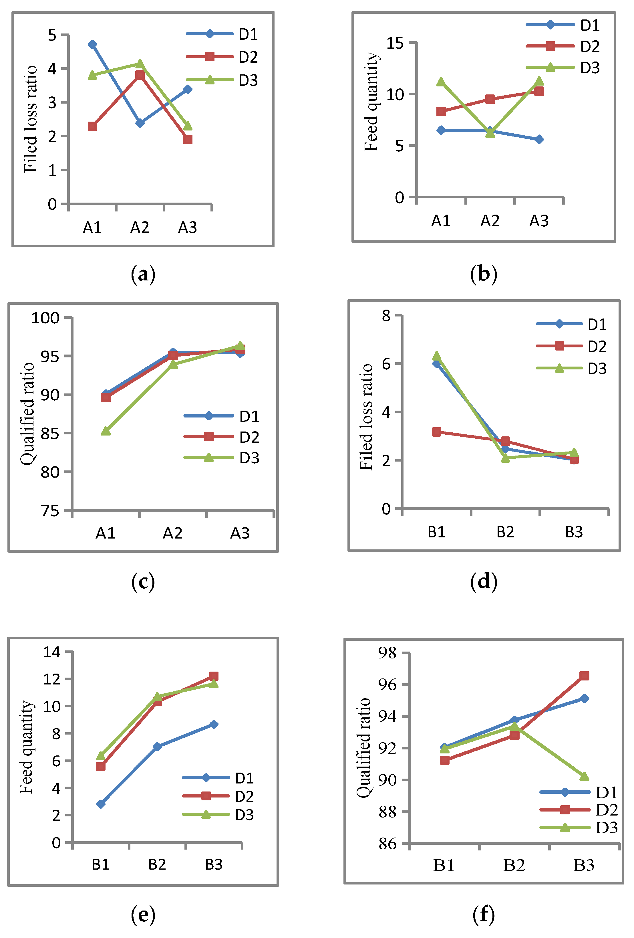
The intuitive analysis of the test results is illustrated in Figure 26, while the interaction effects between D and A, as well as D and B, are graphically represented in Figure 27.
(1) Effects of operational factors on field loss ratio (Sz)
Figure 26a demonstrates that Sz exhibited a decreasing trend with increasing levels of both Factor A and Factor B. When Factor A’s level was elevated, the cutting speed of the chopping blades correspondingly increased. This enhanced cutting speed proved effective in improving the quality of the sugarcane cutting billets [10].
Factor B (number of sugarcane stalks per feeding group) exerted a more pronounced influence on the field loss ratio compared to Factor A. This phenomenon occurred because the basecutter successfully captured nearly all the stalks that came into contact with its disc, subsequently transporting them to the butt lift rollers. Consequently, only minimal billet quantities remained uncollected in the field, resulting in negligible harvest losses.
(2) Effects of factors on the feed quantity (Qw)
Figure 26b illustrates that the feed quantity increased progressively with higher levels of Factors B and D. This observation aligns with the fundamental definition of feed quantity in harvesting operations.
The experimental results demonstrated that the harvester achieved an optimal feeding performance at the tested levels of Factors B and D.
Specifically, Factor B (number of stalks per feeding group) directly influenced the material intake capacity. Factor D (ground speed) affected the continuous flow of feed stock.
The combined effect of these factors ensured efficient material handling throughout the harvesting process.
(3) Effects of factor levels on billet qualification ratio (Cdh)
As shown in Figure 26c, the qualification ratio of billets increased with the increase in levels of Factors A and B. With the level of Factor A increased, the cutting speed of the chopping blades increased. A higher cutting speed was helpful to cutting quality of the billets. As Factor B increases, there were more stalks in the roller train. More stalks was helpful to increase the force of which exerted on the stalks by the upper and lower rollers. This force acted as a support for the chopping blades cutting the stalks. The supported cutting quality usually was better than that of unsupported cutting.
(4) Effects of A×D
When Factors B and C were held constant, the following relationship was observed: increasing factor D (ground speed) resulted in a higher feed quantity (Qw). Higher levels of Factor A (cutting speed) produced the improved cutting quality and reduced the billet length.
As shown in Figure 27c, when Factor A increased from level A1 to A2, the billet qualification rate (Cdh) increased significantly from 85% to 95%. This improvement plateaued near 95% due to random cutting positions along the stalks (including nodal regions and stalk ends).
The mechanisms underlying the results in Figure 25a,b remain unclear and warrant further investigation to better understand the interaction dynamics.
(5) Effects of B×D
When Factor B (stalk grouping number) was maintained at constant levels, the feed quantity (Qw) showed a positive correlation with increasing factor D (ground speed). When the D levels were fixed, Qw increased proportionally with higher B values, as shown in Figure 27e.
This synergistic relationship was attributed to two key mechanical advantages of the harvesting system: the basecutter’s toothed disc assembly exhibited an exceptional lodged cane recovery performance, and the optimized roller configuration demonstrated high conveying efficiency, particularly for densely grouped stalks. Consequently, the combined losses throughout these processes remained consistently low, confirming the strong positive interaction between these operational parameters (Figure 27d).
(6) Determination of Optimal Factor Combination
The optimal treatments for test indicators Sz, Qw, and Cdh shown in Table 4 were A3B2C3D3, A1B3C3D3, and A3B3C1D3, respectively.
The optimal treatments for test indicators Sz, Qw, and Cdh shown in Figure 26a–c were A3B3C2D2, A3B3C3D3, and A3B3C1D1, respectively. Therefore, A3B3 represents the optimal level.
For A×D interaction (Figure 27a–c), A3D2 and A3D3 were better than A3D1 in terms of both Sz and Qw. All the three configurations (A3D1, A3D2, and A3D3) showed an equivalent performance for Cdh.
For B×D interaction (Figure 27d–f), all the three configurations (B3D1, B3D2, and B3D3) showed an equivalent performance for Sz. Both B3D2 and B3D3 were better than B3D1 for Qw. Both B3D1 and B3D2 were better than B3D3 for Cdh. Therefore, D2 is the optimal choice in the case of considering interaction between A×D and B×D.
In Table 5, C, A×C, B×C, and C×D had no significant effect on the three test indicators. In Figure 26a, C2 was best for Sz. In Figure 26b, C3 was best for Qw In Figure 26c, C1was best for Cdh. In this research, Sz had a highest priority than Qw and Cdh, so C2 was selected as the optimal level.
Based on the comprehensive analysis of factor effects, the combination A3B3C2D2 was identified as the theoretically optimal treatment. However, this specific combination was not included in the original orthogonal array (Table 4).
To validate these findings, additional verification tests were conducted following the experimental methodology described in Section 2.6.3.
The experimental results for treatments A3B3C2D2 and A3B2C3D3 (the latter is included in Table 4) are presented in Table 6. Comparative statistical analysis yielded the following findings:
Sz: t = 6.6421 > t(4)0.01 = 3.7496 (p < 0.01).
Qw: t = 0.8486 < t(4)0.05 = 2.138 (p > 0.05).
Cdh: t = 1.895 < t(4)0.05 = 2.1318 (p > 0.05).
Sz showed highly significant differences between treatments. Neither Qw nor Cdh demonstrated statistically significant differences.
Therefore, A3B2C3D3 is the optimal treatment in this research.

3.4. Results and Analysis of the Field Test

Field testing was conducted under severe sugarcane lodging conditions. The operational parameters of ground speed, rotational speed of chopper, and rotational speed of butt lift/feed rollers were set as 1.1 m/s, 390 r/min, and 230 r/min, respectively. Each treatment was replicated three times. The results are as shown in Table 7.
The field test results demonstrated that the developed harvester operated effectively in severely lodged sugarcane fields.
Under typical conditions in the Zhanjiang region, the lodged field yield average is 45,000–60,000 kg/ha, and the conventional field losses during harvesting by a chopper harvester range from 7500 to 12,000 kg/ha. The field loss ratio is about 16–20%.
Comparative analysis revealed that the prototype harvester achieved a significantly lower field loss ratio than the commercial harvesters under identical conditions.

4. Discussion and Conclusions

4.1. Discussion

This study categorized sugarcane harvesting losses into lost losses (unrecovered stalks) and stubble losses (remaining stalk portions) in accordance with the JB/T 6275-2019 Sugarcane Combine Harvester Standard [21]. However, an additional loss mechanism—juice loss during billet chopping—was identified, with the reported losses ranging from 2 to 5 tonnes per hectare [10].
The row profile significantly influenced the field loss ratios during harvesting. Based on prior research [28], the optimal configuration was a slightly rounded mound (100–150 mm elevation above flat inter-rows). In contrast, crater-shaped rows increased the cane losses due to uneven cutting dynamics.
In this study, the test field featured a 150 mm mound profile. This design enabled subsurface cutting (blades operating below ground level), zero stubble loss (complete stalk recovery), and isolation of lost losses (primary focus of optimization). Consequently, the measured field loss ratio exclusively reflected lost losses, aligning with the research objective of minimizing the amount of unrecovered cane.
The experimental results demonstrated that cane losses were primarily governed by two operational parameters of extractor speed (air velocity) and harvester pour rates. In this research, the harvester maintained an average extractor air velocity range of 14–18 m/s during testing, which consistently achieved the target trash content of about 5%.
The current standard chopper harvester configuration utilized an axial flow exhaust fan extractor system. This design required a specific vertical elevation (about 1–2 m) between the billet intake and the elevator billet collection box. As illustrated in Figure 4 and Figure 12, conventional multi-roller systems serve two primary functions of pre-chopping stalk elevation and soil separation prior to extraction.
In this study, the prototype incorporated only two roller pairs, relying instead on an extended billet conveyor for material transport to the extractor. This configuration demonstrated two key characteristics of being beneficial for reducing the harvester length and increasing complexity in conveyor routing. How to reduce the conveyor length, while meeting the impurity removal requirements is the key to realizing the miniaturization of harvesters.
When blades cut stalks beneath the surface of the ground, some soil is carried into the roller train. Multiple rollers were beneficial for discharging the soil before it entered the chopper rollers. Using fewer rollers was not conducive to the removal of soil. This requires the blade to cut stalks at the surface of the ground rather than beneath it.
In China, sugarcane is mainly harvested by hand. The high cost of manual cutting leads to a higher production cost. It further leads to a decrease in planting areas. As a result, sugar mills have not been able to obtain enough sugarcane in recent years. Mechanized harvesting is one of the important measures used to reduce the production cost of sugarcane. However, field losses during mechanized harvesting reduce the available yield. This is a key drawback for farmers and sugar mills when deciding whether to adopt mechanized harvesting. Compared with the existing field loss rate of 15–20% for sugarcane chopper harvesters, the 2% loss rate in this study was beneficial for encouraging farmers and sugar mills to adopt mechanical harvesting. Since 2022, sugarcane chopper harvesters have been difficult to sell in China. The main reason was also the high field loss rate. The technology used in this research is expected to solve this problem.
These sugarcane harvesters have a structural complexity that is basically the same as that of traditional harvesters. Therefore, their durability and manufacturing cost are also basically the same.

4.2. Conclusions

(1) Analysis of high field losses revealed they are caused by three factors: picking up stalks from the ground and conveying them backwards to the butt lift rollers by the basecutter, and conveying them by the roller train.
When the raised patterns and the steel bars on the basecutter disc were covered by sticky soil, they no longer functioned effectively. As a result, the disc failed to lift severely the lodged sugarcane. Additionally, due to their bent shape, curved stalks exiting the basecutter sometimes struggled to enter the gap between the upper and lower butt lift rollers. When these bent stalks passed through multiple roller pairs, they were more likely to contact the side walls of the roller train and detach from it. These issues led to channel blockages, stalk breakage, and stalks being left in the field.
(2) Structural improvements were proposed for the chopper harvester, including installing toothed plates on the upper surface of the cutter disc, establishing an optimal positional relationship between the disc and the butt lift rollers, and reducing the number of roller pairs between the basecutter and the chopper to just one pair of butt lift rollers and one pair of feed rollers.
The mechanisms for reducing field loss were analyzed. The theoretical analysis results indicated the following: The conventional basecutter disc relied on friction force to pick up stalks, whereas the small-toothed plates utilized grabbing force, enabling smoother pickup of severely lodged cane. The disc’s inclination angle needed to be 2° greater than that of the roller train. When Li (the intersection line between the top surface of the cutter disc and the tangential plane) was above Lf (the line of intersection between the central plane of the lower butt lift roller and the tangential plane), but below A (The symmetrical plane between the upper and lower rollers), the stalks could smoothly enter the butt lifter rollers. Using fewer rollers reduced the likelihood of curved canes blockage or detaching from the roller train.
(3) After implementing the above improvement measures, a prototype sugarcane harvester was designed and developed. Four-factor, three-level orthogonal tests were conducted to evaluate its performance in harvesting severely lodged sugarcane. Severely lodged sugarcane was simulated by stalks laid on the ground in the field. Field tests were carried out to assess the harvester’s effectiveness in harvesting growing lodged cane.
The performance test results showed that under the optimal parameter combination—a chopper rotational speed of 390 r/min, 10 sugarcane stalks per group, a butt lift/feed roller rotational speed of 230 r/min, and a ground speed of 1.41 m/s—the field loss ratio, feed quantity, and the billet qualification ratio were 1.21%, 13.09 kg/s, and 95.82%, respectively.
The field tests demonstrated that the harvester could smoothly harvest severely lodged sugarcane. In these tests, the field loss ratio, feed quantity, and the billet qualification ratio were 2.0%, 10.05 kg/s, and 94.2%, respectively. Compared to the 15–20% field loss ratio demonstrated by existing sugarcane chopper harvesters when harvesting lodged cane, the proposed structural improvements significantly reduced the field losses.

Author Contributions

Conceptualization, J.J. and Q.L.; validation, X.H., H.X. and T.W.; formal analysis, X.H.; investigation, J.J., J.F., Y.L. and X.Z.; resources, X.H.; data curation, J.F. and Y.L.; writing—original draft preparation, J.J.; writing—and editing, J.J., H.X. and Q.L.; visualization, X.H.; supervision, Q.L.; project administration, Q.L.; funding acquisition, T.W. All authors have read and agreed to the published version of the manuscript.

Funding

This research was funded by the “China National Major Agricultural Research Project” and the “China National Modern Agricultural Industry Technology System”, grant number 170402.

Data Availability Statement

This experiment was conducted in January 2018. The data presented in this study are available on demand from the communication author at qingting@scau.edu.cn.

Conflicts of Interest

The authors declare no conflicts of interest.

References

  1. Younos, M.A.; Embaby, E.M. Natural occurrence of fungi and aflatoxins associated sugarcane plant and sugarcane juice and their Control. Indian J. Microbiol. 2024, 64, 500–510. [Google Scholar] [CrossRef] [PubMed]
  2. Wen, C.; Yan, Y.; Wu, W.; Li, J.; Hou, B.; Cui, W.; Huang, Y.; Li, K.; Long, X.; Nong, H. Height detection of crop divider toes of sugarcane harvester based on Kalman adaptive adjustment. Sci. Rep. 2023, 13, 16817. [Google Scholar] [CrossRef] [PubMed]
  3. Bai, J.; Ma, S.; Wang, F.; Xing, H.; Ma, J.; Wang, M. Performance of crop dividers with reference to harvesting lodged sugarcane. Sugar Tech 2020, 22, 812–819. [Google Scholar] [CrossRef]
  4. Liu, Q.; Chen, J.; Ou, Y. Spatial attitude of lodged sugarcane stalk in field. In Proceedings of the ASABE’s Annual International Meeting 2012, Dallas, TX, USA, 29 July–1 August 2012. [Google Scholar]
  5. Bai, J.; Ma, S.; Wang, F.; Xing, H.; Ding, Z.; Hu, J. Lifting performance of crop dividers with variable pitch spiral scrolls. Sugar Tech. 2022, 24, 1877–1886. [Google Scholar] [CrossRef]
  6. Wu, T.; Ren, J.; Liu, Q.; Zou, X.; Zhang, Z.; Zhou, S.; Feng, J.; He, L. Development of the 4GDZ-132 sugarcane chopper combine harvester. Trans. Chin. Soc. Agric. Eng. 2022, 38, 30–38. (In Chinese) [Google Scholar]
  7. Ma, S.; Scharf, P.A.; Karkee, M.; Zhang, Q. Performance evaluation of a chopper harvester in Hawaii sugarcane fields. In Proceedings of the 2014 ASABE International Annual Meeting, Montreal, Canada, 13–16 July 2014; American Society of Agricultural and Biological Engineers: St. Joseph, MI, USA, 2014; p. 1. [Google Scholar]
  8. Lu, H.; Wu, T. Reflection on development status of mechanized sugarcane harvesting in Guangxi. Sugarcane Canesugar 2023, 52, 53–59. [Google Scholar]
  9. Jiang, J.; Yang, Y.; Wu, C.Y.; Liu, Q.T.; Ou, Y.G.; Mo, Q.G.; Xia, M.; Wu, T.; Liang, S. Analysis on reasons for the slow advance of sugarcane harvesting mechanization in China. Sugarcane Canesugar 2022, 51, 1–5. [Google Scholar]
  10. Gary, S.; John, A. The Harvesting Best Practice Manual for Chopper-Extractor Harvester; Bureau of Sugar Experiment Station: Brisbane, Australia, 2002. [Google Scholar]
  11. Kerr, B.; Blyth, K. 100 Years of Mechanical Cane Harvesting; Canegrowers: Ingham, Australia, 1993. [Google Scholar]
  12. Dias Neto, A.F.; Albiero, D.; Rossetto, R.; Biagi, J.D. Modeling of Mechanized Sugarcane Harvesting to Support Decision-Making on Asset Management. Sugar Tech. Int. J. Sugar Crops Relat. Ind. 2022, 24, 798–812. [Google Scholar] [CrossRef]
  13. Wang, Q.; Zhou, G.; Huang, X.; Song, J.; Xie, D.; Chen, L. Experimental research on the effect of sugarcane stalk lifting height on the cutting breakage mechanism based on the sugarcane lifting-cutting system (SLS). Agriculture 2022, 12, 2078. [Google Scholar] [CrossRef]
  14. Qiu, M.; Meng, Y.; Li, Y.; Shen, X. Sugarcane stem cut quality investigated by finite element simulation and experiment. Biosyst. Eng. 2021, 206, 135–149. [Google Scholar] [CrossRef]
  15. Qian, J.; Ma, S.; Xu, Y.; Liang, W.; Zhou, B.; Li, W. Analysis of crack stress intensity factor of sugarcane cutting based on fracture mechanics. Trans. Chin. Soc. Agric. Mach. 2023, 54, 101–109. (In Chinese) [Google Scholar]
  16. Ding, Z.; Ma, S.; Zhang, X.; Liang, W.; Li, L.; Su, C. Ultrasonic sensor-based basecutter height control system of sugarcane harvester. Sugar Tech 2023, 25, 453–459. [Google Scholar] [CrossRef]
  17. Li, H.; Yang, J.; Song, J.; Sun, M.; Wei, W.; Zhang, S.; Wu, T.; Li, Y. Stem base detection in sugarcane plants using improved YOLOv5m model. Sugar Tech 2025, 1–11. [Google Scholar] [CrossRef]
  18. Davis, R.J.; Norris, C.P. Improving the feeding ability of sugarcane harvesters. In Proceedings of the 2002 Conference of the Australian Society of Sugar Cane Technologists, Cairns, Australia, 29 April–2 May 2002; pp. 190–198. [Google Scholar]
  19. Wang, M.; Liu, Q.; Ou, Y.; Zou, X. Determination of physical and mechanical properties of sugarcane single-bud billets. J. ASABE 2022, 65, 1029–1038. [Google Scholar] [CrossRef]
  20. Ma, L.; Huang, W.; Li, S.; Huang, Z.; Teng, X. Parameters calibration of discrete element model for latosolicred soil of sugarcane in Guangxi Autonomous Region. J. Agric. Mech. Res. 2023, 45, 18–26. [Google Scholar]
  21. JB/T 6275-2019; Sugarcane Combine Harvester. Ministry of Industry and Information Technology of the People’s Republic of China: Beijing, China, 2019.
  22. CASE A8000 and A8800 Cane Harvesters Operator’s Manual, 84158982-01; Case IH: Sydney, Australia, 2009.
  23. Available online: https://www.deere.com/en/search/?term=Sugar+Cane+Harvester (accessed on 10 April 2025).
  24. Wang, F.; Ma, S.; Xing, H.; Bai, J.; Ma, J.; Hu, J.; Yang, Y. High-speed photography analysis on sugarcane base cutting process of contra-rotating basecutters. Sugar Tech 2021, 23, 1118–1125. [Google Scholar] [CrossRef]
  25. Qiu, C.; Mo, H.; Li, S.; He, G.; Zeng, B.; Yang, D. Experimental research on influence factors of the sugarcane ratoon cutting quality undervibration conditions. In Proceeding of the IncoMe-VI and Tepen 2021, Tianjin, China, 20–23 October 2021; Springer: Cham, Switzerland, 2023. [Google Scholar] [CrossRef]
  26. Wang, F.L.; Ma, S.C.; Xing, H.N.; Bai, J.; Ma, J.-Z.; Wang, M.-L. Effect of contra-rotating basecutter parameters on basecutting losses. Sugar Tech Int. J. Sugar Crops Relat. Ind. 2021, 23, 278–285. [Google Scholar] [CrossRef]
  27. Xie, L.; Wang, J.; Cheng, S.; Zeng, B.; Yang, Z. Performance evaluation of a chopper system for sugarcane harvester. Sugar Tech. 2019, 21, 825–837. [Google Scholar] [CrossRef]
  28. Hogarth, D.M.; Allsopp, P.G. Manual of Canegrowing; Sugar Research Australia: Brisbane, Australia, 2000. [Google Scholar]
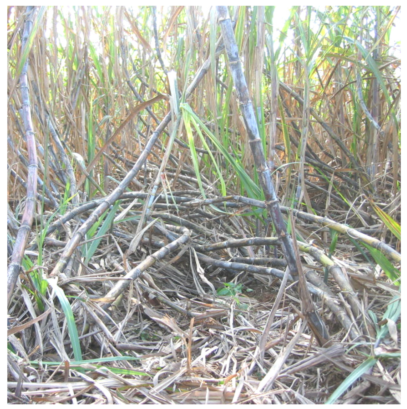
Figure 1. Canes exhibiting severe lodging in field conditions.
Agriculture 15 01759 g001
Figure 2. Methodology followed for the development of technology for reducing field losses during lodged sugarcane harvesting.
Agriculture 15 01759 g002
Figure 3. Experimental device and samples: (a) samples placed horizontally; (b) samples placed vertically.
Agriculture 15 01759 g003
Figure 4. The definitions of the lodging angle and lateral deviation angle of sugarcane.
Agriculture 15 01759 g004
Figure 5. Operational workflow of CASE A8000 sugarcane harvester. 1—sugarcane. 2—topper. 3—chopper rollers. 4—primary extractor. 5—billets. 6—extractor. 7—crop divider. 8—knock down roller. 9—power feed roller. 10—basecutter. 11—butt lifter roller. 12—roller train. 13—elevator.
Agriculture 15 01759 g005
Figure 6. Structure of basecutter: (a) raised patterns on upper surfaces; (b) deformed steel bars on upper surfaces. 1—disc. 2—blade. 3—raised patterns. 4—toothed paddle. 5—deformed steel bar.
Agriculture 15 01759 g006
Figure 7. Force analysis of sugarcane being picked up and transferred by disc of basecutter: (a) stalk was cut at its base; (b) force analysis of straight stalk; (c) force analysis of curved stalk. 1—sugarcane. 2—knock down roller. 3—disc of basecutter. 4—ground of field. 5—straight stalk. 6—curved stalk.
Agriculture 15 01759 g007
Figure 8. Upper surface of disc with sticky soil: 1—blade; 2—sticky soil.
Agriculture 15 01759 g008
Figure 9. Cane that failed to enter channel between upper and lower rollers. 1—curved cane. 2—basecutter. 3—butt lift roller. 4—channel.
Agriculture 15 01759 g009
Figure 10. Analysis of the positional relationship between the basecutter and butt lift rollers. (a) Li was above Lf. (b) Li was below Lf. (c) position relationship between Li and A. A, conveying plane; B, tangential plane; Lf, feeding line; Li, cutter disc feeding roller line.
Agriculture 15 01759 g010
Figure 11. Schematic diagram of butt lift rollers and feed rollers: (a) butt lift rollers; (b) feed rollers. 1—blade of upper roller. 2—sugarcane. 3—blade of lower butt lift roller. 4—rebar rod along edge. 5—upper roller. 6—lower roller.
Agriculture 15 01759 g011
Figure 12. Schematic of curved sugarcane stalk detachment from roller train: (a) roller arrangement and positional relationships; (b) detachment process of curved stalk. 1—basecutter; 2—butt lift roller; 3—feed roller; 4—transitional roller; 5—critical circle; 6—chopper; 7—sugarcane stalk.
Agriculture 15 01759 g012
Figure 13. Schematic diagram of force analysis of cane in roller train: (a) forces on cane from roller train; (b) forces on straight cane; (c) forces on bending cane. 1—basecutter. 2—butter lift roller. 3—feed roller. 4—cane. 5—chopper. 6—side wall of roller train.
Agriculture 15 01759 g013
Figure 14. Mechanism of lodged sugarcane stalk engagement using toothed plates: (a) stalk is perpendicular to toothed plate; (b) stalk is not perpendicular to toothed plate; (c) contact points between stalk and toothed plate. 1—small-toothed plate. 2—sugarcane.
Agriculture 15 01759 g014
Figure 15. Geometric relationship between basecutter orientation and roller train configuration. 1—disc of basecutter. 2—butter lift roller. 3—feed roller. 4—crawler wheel. 5—chopper roller. 6—fixed frame. 7—hydraulic cylinder.
Agriculture 15 01759 g015
Figure 16. Schematic diagram of CLASS 1400 sugarcane harvester’s structural layout: (a) structure diagram; (b) structure image. 1—divider. 2—basecutter. 3—chopper. 4—walking wheel. 5—billet conveyor. 6, 8—extractor fan. 7—engine. 9—billet elevator. 10—cab. 11—topper.
Agriculture 15 01759 g016
Figure 17. Schematic diagram of cane base cutting and chopping. 1,5—sugarcane. 2—basecutter. 3—lower chopper roller. 4—billet conveyor. 6—upper chopper roller. 7—billets brought back by blade. 8—billets fallen onto the conveyor.
Agriculture 15 01759 g017
Figure 18. This figure illustrates key dimensional parameters of basecutter assembly: (a) structural dimensions of basecutter; (b) A-A view; (c) small-toothed plate. 1—gear box. 2—axis of disc. 3—toothed paddle. 4—small-toothed plate. 5—blade.
Agriculture 15 01759 g018
Figure 19. Dimensions schematic of roller train and chopper rollers. 1—butter lift rollers. 2—feed rollers. 3—chopper rollers.
Agriculture 15 01759 g019
Figure 20. Dimensional drawing of chopper assembly. 1—blade. 2—adjusting bolt. 3—upper chopper roller. 4—fastening bolt. 5—overlap area. 6—lower chopper roller. 7—blade.
Agriculture 15 01759 g020
Figure 21. Structure dimension of billet conveyor: (a) structure of billet conveyor; (b) isometric views of scraper; (c) structural dimension of scraper. 1—scraper. 2—lower chain track. 3—upper chain track. 4—porous plate. 5—bed of conveyor. 6—hydraulic motor.
Agriculture 15 01759 g021
Figure 22. Design diagram of HN4GDL-91 sugarcane harvester.
Agriculture 15 01759 g022
Figure 23. HN4GDL-91 harvester field test configuration illustrating standardized billet collection method.
Agriculture 15 01759 g023
Figure 24. Layout schematic of sugarcane laying in field.
Agriculture 15 01759 g024
Figure 25. Lodged stalks with curved sections: (a) one curved section; (b) two curved sections.
Agriculture 15 01759 g025
Figure 26. Influence trends and range analysis of factors on indicators: (a) factor effects on field loss ratio; (b) factor effects on feed quantity; (c) factor effects on qualification rate of billets.
Agriculture 15 01759 g026
Figure 27. Effects of A×D and B×D interactions on performance indicators: (a) effects of A×D on Sz; (b) effects of A×D on Qw; (c) effects of A×D on Cdh; (d) effects of B×D on Sz; (e) effects of B×D on Qw; (f) effects of B×D on Cdh.
Agriculture 15 01759 g027
Table 1. Parameters of HN4GDL-91 sugarcane harvester.
ParametersValues
Overall size L × W × H (mm)6355 × 1780 × 2940
Track length L1/track gauge L2 (mm)3480/1230
Engine rated power (kW)91
Displacement of the motor of knockdown roller (mL/r)160
Displacement of the motor of basecutter (mL/r)80
Displacement of the motor of butt lift/feed roller (mL/r)200
Displacement of the motor of chopper (mL/r)200
Displacement of the motor of billet conveying device (mL/r)125
Table 2. Factors and level assignments for L27(313) orthogonal test.
A: Rotational Speed of Chopper (r/min)B: Numbers of Stalks in a GroupC: Rotational Speed of Butt Lift/Feed Rollers (r/min)D: Ground Speed
(m/s)
12305150slow (0.65)
231010190medium (1.09)
339015230fast (1.41)
Table 3. Test results of the static friction coefficient (SFC) between sugarcane and soil/sugarcane and steel.
OrientationSampleMC123MeanStandard Error
SoilVerticalDL5%0.70.790.710.730.03
10%0.80.80.910.840.04
15%0.590.620.560.590.02
WL5%0.740.730.850.770.04
10%0.790.880.820.830.03
15%0.410.510.560.50.04
HorizontalDL5%0.720.760.80.760.02
10%0.690.790.930.80.07
15%0.40.560.530.50.05
WL5%0.920.930.840.90.03
10%0.620.710.590.640.03
15%0.750.730.720.730.01
SteelVerticalDL 0.480.460.490.480.01
WL 0.40.390.420.40.01
HorizontalDL 0.510.440.490.480.02
WL 0.470.490.470.480.01
Note: DL was sample de-leafed, WL was sample with leaves attached.
Table 4. Results of orthogonal test of performance.
No.ABA×BCA×CB×CDA×DB×DC×DSz/%Qw/kg/sCdh/%
111111111119.002.3089.90
211112222221.766.0287.21
311113333336.305.6590.66
412221122232.559.5086.29
512222233312.959.1786.48
612223311123.307.6187.57
713331133322.1818.7778.71
813332211131.849.5492.78
913333322212.579.4095.39
1021231213313.443.1295.24
1121232321126.115.4192.20
1221233132238.326.0090.24
1322311221133.819.4196.10
1422312332212.129.8595.99
1522313113321.926.6996.45
1623121232222.002.7995.53
1723122313331.809.4494.76
1823123121111.5113.6796.91
1931321312215.573.0091.01
2031322123321.645.2494.30
2131323231134.347.4294.95
2232131323332.0112.0496.02
2332132131111.2113.0997.65
2432133212222.196.7697.26
2533211331121.3713.3496.43
2633212112232.417.0297.83
2733213223312.0713.5297.36
Note: The factors and their levels are as shown in Table 3.
Table 5. Analysis of variance (ANOVA) for orthogonal test results.
Performance IndicatorsSz, %Qw, kg/sCdh,%
Sourcesigsigsig
A0.4210.5400.004 **
B0.010 *0.011 *0.435
A×B0.6790.8580.575
C0.7740.5120.442
A×C0.3280.9820.394
B×C0.6180.5880.610
D0.570.0980.516
A×D0.0 **0.0 **0.0 **
B×D0.0 **0.0 **0.0 **
C×D0.3670.9430.428
Note: * represents a significant impact with a 95% confidence interval; ** represents a significant impact with a 99% confidence interval.
Table 6. Test results of treatments A3B3C2D2 and A3B2C3D3.
Sz, %Qw, kg/sCdh,%
A3B3C2D211.81,13.4197.81
21.7414.598.28
31.5812.9296.85
Mean1.7113.6197.65
Standard error0.0650.4670.421
A3B2C3D311.2613.2995.62
21.1513.6597.41
31.2212.3494.42
Mean1.2113.0995.82
Standard error0.0320.3910.869
t-test value6.64210.8486−1.8958
Table 7. Results of field test.
Parameters123MeanStandard Error
Feed quantity, kg/s10.111.210.210.50.287
Ratio of stubble broken, %12.913.212.312.80.215
Ratio of trash content, %5.94.244.70.492
Field loss ratio, %2.11.72.22.00.125
Qualification rate of the billets, %92.995.194.694.20.544
Unit diesel consumption ratio, kg/ha125.8127.2127.4126.80.411
Disclaimer/Publisher’s Note: The statements, opinions and data contained in all publications are solely those of the individual author(s) and contributor(s) and not of MDPI and/or the editor(s). MDPI and/or the editor(s) disclaim responsibility for any injury to people or property resulting from any ideas, methods, instructions or products referred to in the content.