Abstract
During high-speed corn sowing at 10 km/h, the rapid seed discharge resulting from the high rotation speed of the seed disc escalates the impact force of seeds as they are released from the seed metering device into the seed guiding apparatus, consequently diminishing the overall seeding efficiency of the seeder. This study employed high-speed videography to conduct experiments and optimize parameters for the seed-receiving mechanism of a belt-driven seed guide tube. By changing the clamping wheel speed and seed-receiving angle, the speed change curve and displacement trajectory of seeds under different conditions were obtained and analyzed. The findings demonstrate that the seed speed fluctuation is more stable, and the seed displacement trajectory achieves greater stability at a clamping wheel speed of 560 r·min−1. When the seed-receiving angle is set at 85°, the seed speed fluctuation becomes less apparent, resulting in a smoother seed displacement trajectory. Finally, the experimental results of high-speed cameras are confirmed by field tests. The findings of this study can act as a theoretical basis for the further optimization of the experimental belt-driven seed guide tube.
1. Introduction
More than 170 countries and regions cultivate corn, which is the highest-yielding cereal crop and the most significant feed grain [1]. The top three producers, the United States, China, and Brazil, together accounted for more than 60% of the world’s corn production in 2020, when it was estimated to be 1.2039 billion tons [2]. The main corn-growing regions in the United States are concentrated along the Great Lakes, and those in China are primarily dispersed in the Northeast, North China, and Southwest regions [3]. High-speed sowing is a practical method for reducing sowing time, lowering labor costs, enhancing sowing quality and uniformity, and raising yield and revenue. Therefore, the importance of high-speed sowing for corn cultivation is self-evident [4,5,6]. To facilitate high-speed seed guiding and minimize seed collisions, the belt-driven seed guide tube employs a seed belt for comprehensive seed constraint, ensuring a consistent and orderly discharge of seeds from the seed metering apparatus. This kind of seed guiding mode meets the working requirements of the seeder under high-speed sowing conditions [7,8]. However, the transfer of seeds from the seeding apparatus to the guiding belt’s seed cavity experiences instability [9]. As a result, this study concentrates on improving the operational stability of a belt-driven seed guide tube through the optimization of critical elements within its seed-accepting mechanism.
The optimal design and testing of belt-driven seed guide tubes is one of the hot topics of current research, mainly involving the structural parameters, transmission mechanism, motion characteristics, seeding quality, and other aspects of belt-driven seed guide tubes [10,11]. Chen Xuegeng et al. devised a belt seed guiding apparatus associated with the disc speed and seeder walking speed and integrated with the transmission and seeding mechanisms based on the analysis of the hole-forming time balance of an air suction seeder. They determined the main structural parameters of the air suction seeder belt-driven seed guide tube [12]. Ma Chengcheng et al. utilized discrete element method simulation software to emulate the receiving capabilities of the high-speed belt-driven seed guide tube. They analyzed the stress variations on seeds under different conditions, including the presence of a herringbone pattern, varying wheel center distances, etc. This paper discusses the influence of the above parameters on the stress and speed change in seeds [13]. Tang Han et al. improved and designed a finger-clamp precision corn seed metering device by means of clamping seed filling, vibrating seed cleaning, and flexible seed guiding, analyzed its working principle, optimized the structural parameters of key components, and obtained its best working combination parameters through bench tests, so as to achieve the operation requirements of high single seed rate, high-speed uniformity, and low damage [14]. Lü Jinqing et al. evaluated the performance of belt-type seed metering mechanisms based on theoretical analysis, numerical simulation, and field test methods [15]. They established a mathematical model for calculating the theoretical single-seed plant rate, reseeding rate, miss-seeding rate, coefficient of variation (CV) for plant spacing, and theoretical seeding amount per unit area under different working conditions. They utilized EDEM 2020 software to simulate the motion attributes of seeds within belt-type seed metering mechanisms across various operational scenarios, deriving insights into seed distribution on the belt surface, seed-to-belt surface contact forces, and other pertinent factors.
In addition to the advancements made by Chinese scholars, researchers from the United States, Kocher, Michael F., et al., researched how the condition of the seed tube impacts the uniformity of corn seed spacing. Through experiments and analyses, they provided valuable insights into understanding the relationship between seed tube characteristics and the crucial aspect of seed spacing uniformity during the corn seeding process [16]. Furthermore, Karayel D. et al. have developed an innovative helicoidal seed tube. This helicoidal tube is designed to be affixed to the end of a conventional delivery tube in a seed drill, with the objective of regulating the flow of seeds as they are dispensed into the soil. The helicoidal design operates by utilizing the frictional reaction generated as the falling seeds traverse through the helix. This mechanism effectively modulates the velocity of the descending seeds, thereby enhancing the uniformity of seed distribution [17]. Another study was conducted by Daniel Savi et al., which aimed to evaluate the impact of seed tube curvature on the longitudinal distribution of corn and soybean seeds at varying sowing speeds. The results of this research indicated that the curved seed tube exhibited the highest efficiency concerning the measured parameters for both corn and soybean. Furthermore, it was noted that an increase in sowing speed adversely affected the evaluated parameters, particularly in soybean cultivation [18].
In conclusion, the quality of high-speed seeding operation depends largely on the structure and working performance of the seed guide device of the seeder. The belt-driven seed guide tube is a practical way to increase the seeding efficiency of seeders, with a wide range of potential applications and research value. At present, there are many studies on the optimization and design of simple seed guide tubes or seed-conveying belts, but few on seed-receiving mechanisms. As a transitional part between the seed metering device and the seed-conveying belt, the seed-receiving mechanism is directly related to the subsequent seed guiding effect. Therefore, based on high-speed videography technology, this study tested the working parameters of the main and secondary clamping wheels of the seed-receiving mechanism and explored the influence law of the changes in these parameters on the seed-receiving effect, providing an experimental basis for the structure and parameter optimization of the seed guide tube in the future. This study aims to enhance the stability of corn seed transition from the seed metering device to the belt-driven seed guide tube during high-speed sowing, thereby enabling efficient and rapid sowing operations.
2. Materials and Methods
2.1. Structure and Operational Principles of the Belt-Driven Seed Guide Tube
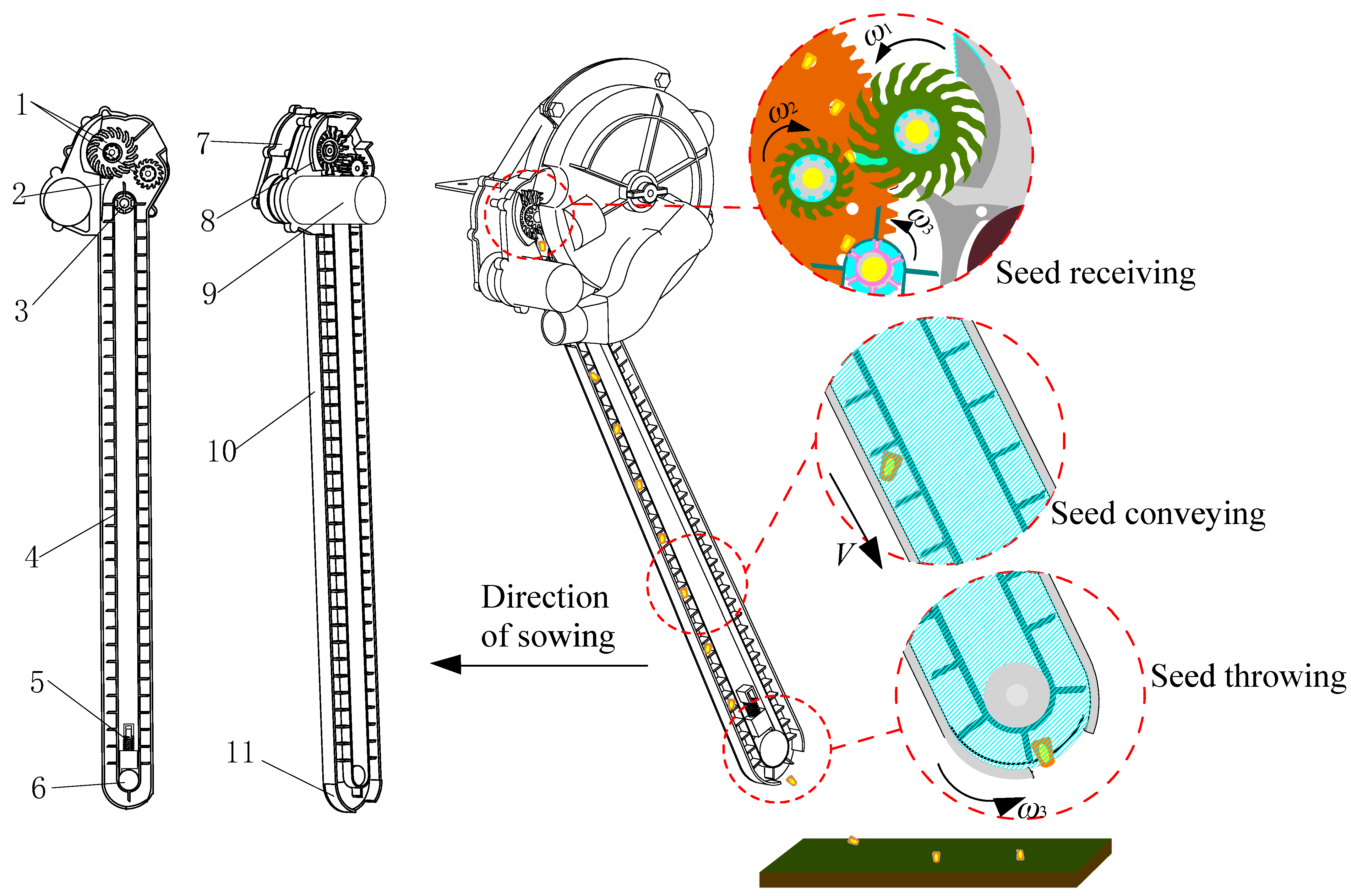
Figure 1 illustrates the structural layout of the belt-driven seed guide tube. It comprises crucial parts, including a clamping wheel, cleaning seed parts, a driving/driven band wheel, a seed-conveying belt, a tightener, a transmission gearbox, a shield, a casing, and a servo actuator.
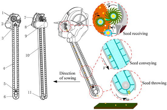
Figure 1.
Diagram showcasing the configuration of the belt-driven seed guide tube: 1. Clamping wheel 2. Cleaning seed parts 3. Driving band wheel 4. Seed-conveying belt 5. Tightener 6. Driven band wheel 7. Transmission gearbox 8. Shield 9. Servo-actuator 10. Casing 11. Seed throwing plate.
This belt-driven seed guide tube replaces the seed discharge port and traditional seed guide tube of the air-suction corn precision seed metering device. The seed guide tube can quickly and accurately clamp the seeds from the disc-shaped hole of the seed disc and send them into the seed-conveying belt cavity by means of rotating the clamping wheel, which not only greatly improves the speed of the seed-guiding operation but also ensures the uniformity and accuracy of the seeding process and improves the working performance of the whole machine under high-speed seeding operation [19,20,21,22].
2.2. Configuration and Operational Concept Regarding Seed-Receiving Mechanism
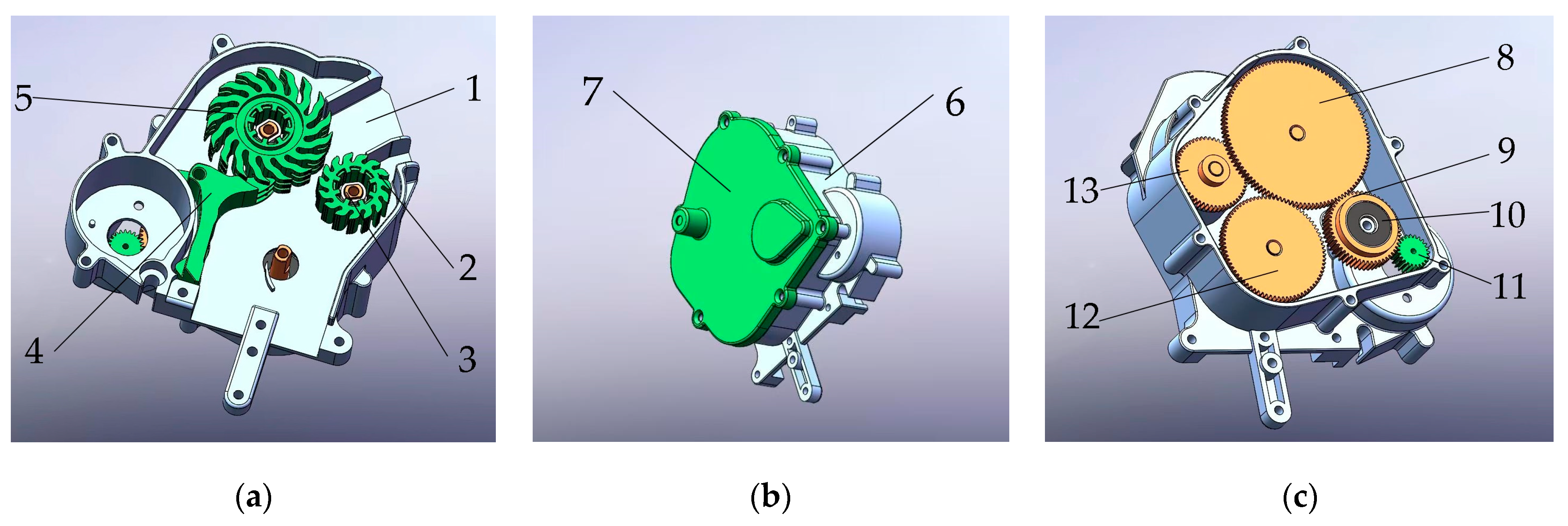
Compared with other conventional seed-guiding devices, the seed guide tube is equipped with a seed-receiving mechanism, and the movement of the seeds is constrained by the rotation and pinch of the clamping wheel so as to improve the stability and accuracy of the seeds entering the seed-conveying belt cavity from the seed disc in the process of high-speed sowing and effectively reduce the bouncing collision of the seeds during the movement. The seed-receiving mechanism of the seed guide tube is mainly composed of the main and secondary clamping wheels, cleaning seed parts, the shaft body, the transmission gearbox, the servo actuator, and the back cap (Figure 2). Among them, the main and secondary clamping wheel is one of the core components of the mechanism, which effectively restricts the movement of seeds through rotation and pinch. When the seed disc sends the seeds to the seed-receiving mechanism, it is driven by the high-speed rotating main and secondary clamping wheel to clamp the seeds and control their movement direction, which directly affects the stability and accuracy of the seeds’ transition from the seed disc to the seed-conveying belt cavity. The clamping wheel is made of rubber material, and the cleaning seed parts are arranged at the lower side of the main clamping wheel to avoid the seed-receiving work being affected because the seeds are stuck between the fingers of the main clamping wheel. The radius ratio of the main clamping wheel and the secondary clamping wheel is 1.7:1, and fingers with inclined arc structure are evenly distributed around the clamping wheel, of which 17 fingers are distributed on the main clamping wheel, and 15 fingers are distributed on the secondary clamping wheel.
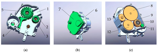
Figure 2.
Schematic representation of the seed-receiving mechanism: 1. Seed collection port 2. Secondary clamping wheel 3. Shaft body 4. Cleaning seed parts 5. Main clamping wheel 6. Shell 7. Back cap 8. Drive main clamping wheel gear 9. Transition gear 10. Ball bearing 11. Servo motor gear 12. Drive pulley gear 13. Drive secondary clamping wheel gear. (a) Front of the device; (b) Back of the device; (c) Gear transmission layout.
According to the operation process of the seed-receiving mechanism, it is divided into three working stages: clamping seeds, transporting seeds, and discharging seeds. When the seed disc carries a single seed to the seed-receiving port, the flexible main and secondary clamping wheels “pick” the seed by rotating and clamping, and the working process is to clamp the seed. The clamped seeds move under the rotating clamping of the main and secondary clamping wheels, and the working process is to transport the seeds. Then, the clamping wheel discharges the seeds into the seed cavity of the lower seed-conveying belt, and the working process is to discharge the seeds. The method of “picking” and then “releasing” the seeds by using the clamping wheel can stably transfer the seeds from the seed metering device to the belt-driven seed guide tube without damaging the seeds.
2.3. Design and Analysis for Seed-Receiving Mechanism
2.3.1. Geometric Parameters of Corn Seed
The design of the seed-receiving mechanism is heavily influenced by the geometric characteristics of corn seed [23,24,25]. In designing the parameters for the receiving mechanism, the geometric characteristics of different corns are essential reference points. Demiya No. 1, Heyu 187, and Fenghe No. 7—three widely grown varieties in northern China—were chosen as the measurement objects. Table 1 displays the findings after measuring their length, width, and thickness.

Table 1.
Three-dimensional measurement of different seeds.
Table 1 shows that there are significant size variations between various corn seed varieties as well as some variations within the same variety. The biggest difference between them is in their length, while their differences in width and thickness are generally smaller.
2.3.2. Seed-Receiving Gap of Main and Secondary Clamping Wheels
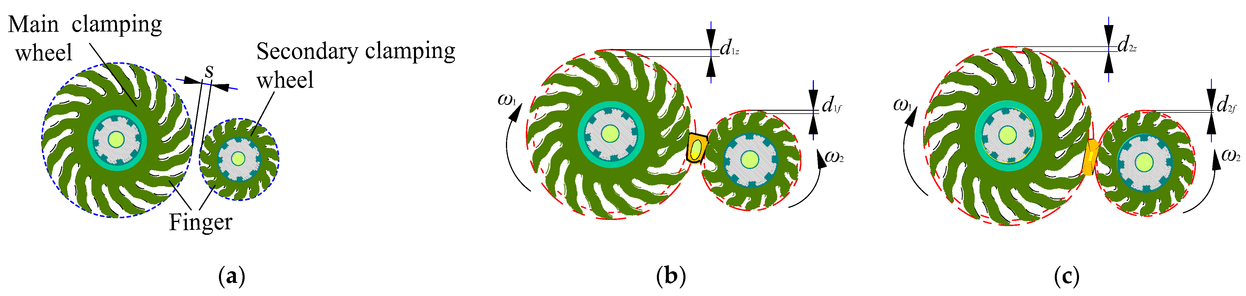
The effectiveness of seed reception is notably impacted by the width of the seed-receiving clearance between the main and secondary clamping wheels. As shown in Figure 3a, ‘s’ represents the gap width between the main and secondary clamping wheels. The clamping wheels will lose their ability to clamp the seeds if the gap width is too large, which can lead to issues like natural seed drop and disruption of the initial seed flow [26]. Problems like seed being bounced by the clamping wheels will happen if the gap width is too small. The width of the seed-receiving gap in this section is created using the shape and adsorption posture of corn seed as a guide. The two main categories of the seed adsorption posture are vertical and lateral [27]. To ensure full clamping of lateral seeds (as depicted in Figure 3b) and unimpeded passage of upright seeds (as shown in Figure 3c), it is imperative for the seed-receiving clearance width to be adequate. As a result, the clamping wheels should be equipped with elastic fingers to receive the seeds by rotating and clamping. If the center of the hole contains the adsorbed corn seed, then:
where ta is the height at the tip of the upright seed, typically ranging from 1 to 1.5 mm; where ta = 1.5 mm is used, tb is the height at the bottom of the upright seed, usually between 2.5 and 3 mm, with tb = 3 mm chosen, s is the gap width.

Figure 3.
Various adsorption postures of corn seeds passing through the gap between the clamping wheels: (a) Gap width between the main and secondary clamping wheels; (b) lateral seeds pass through the gap of the clamping wheels; (c) upright seeds pass through the gap of the clamping wheels.
The result of Equation (1) is 1.5 ≤ s ≤ 3 mm; s is chosen as the intermediate value of 2.3 mm to ensure that the clamping wheels can adapt to most corn seeds as much as possible.
2.3.3. Deformation Parameters of Finger
According to the schematic diagram of Figure 3, the formulas of the largest and smallest total shape variable of fingers on the main and secondary clamping wheel can be expressed as follows:
where wb is the width of the end of the lateral seed, which is generally 7–8.5 mm, and here 8.5 mm is taken, d1z is the largest shape variable of the main clamping wheel’ finger, d2z is the smallest shape variable of the main clamping wheel’ finger, d1f is the largest shape variable of the secondary clamping wheel’ finger, d2f is the smallest shape variable of the secondary clamping wheel’ finger, dmax is the largest total shape variable parameters of the main and secondary fingers, and dmin is the smallest total shape variable parameters of the main and secondary fingers.
From Equation (2), the smallest shape variable value of the finger (dmin) is calculated as 0.7 mm, while the largest total shape variable value (dmax) amounts to 6.2 mm.
2.3.4. Clamping Wheel Speed
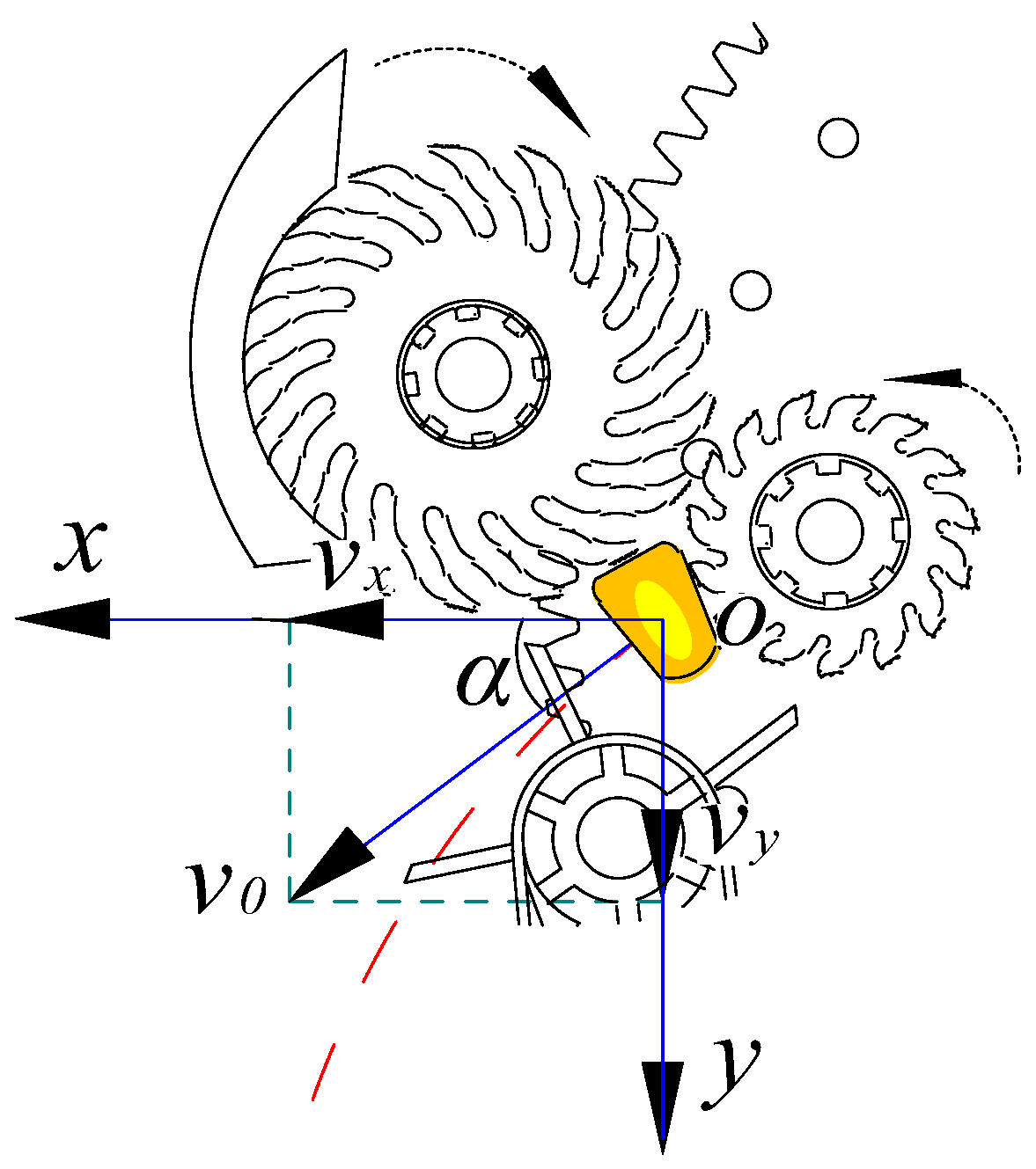
The seeds are discharged into the seed-conveying belt cavity after being moved by the clamping wheel, and Figure 4 depicts the speed of the seeds during this process.

Figure 4.
Schematic diagram of the gap width between the main and secondary clamping wheels.
When the seeds enter the seed-conveying belt cavity, they make a parabolic motion in the downward-inclined speed direction, and the formula is as follows:
Among them,
where vx is the abscissa component velocity, vy is the ordinate component velocity, R is the clamping wheel radius, n2 is the clamping wheel rotation speed, v0 is the total seed velocity, α is the incident angle, a is the acceleration of the seed falling after it is released by the clamping wheel, and t is the time when the seed enters the conveying belt cavity.
Combining Equations (3) and (4) results in Equation (5).
According to Equation (5), the speed at which seeds fall into the cavity is associated with the rotation speed and radius of the clamping wheel. The initial velocity of the downward oblique parabolic trajectory and the entry speed into the seed-conveying belt cavity escalate in tandem with the clamping wheel’s rotational speed. If this speed is too high, the seeds will collide violently when they come into contact with the seed-conveying belt and then pop out of the seed cavity, which will affect the subsequent seed guide effect and reduce the sowing accuracy of the whole seeder. The fingers made of rubber on the surface of the clamping wheel will bend when they come into contact with the seeds during the seed-receiving process so that the radius of the clamping wheel will change at any time. To improve the operability and accuracy of the experiment, this paper conducts high-speed videography experiments and analyzes the clamping wheel speed.
2.3.5. Finger Structure
Through a series of pre-experiments, the optimal parameters for the design of the clamping wheel fingers were determined. The inclined arc structure is selected as the finger shape of the clamping wheel. In order to clamp seeds conveniently, the initial inclination angle of the main wheel fingers is 30°, the spacing angle between fingers is 21°, and the number of main wheel fingers is 17. With the secondary wheel finger inclined at 30°, an inter-finger spacing of 24°, and 15 fingers on the secondary wheel, the main wheel finger thickness is 2.5 mm, while the secondary wheel finger is 2 mm thick. During seed reception, the maximum total deformation of both main and secondary fingers reaches 6.2 mm. The total deformation value is distributed, assuming that the main wheel deformation value is 5 mm, the secondary wheel deformation value is 1.2 mm, then the main wheel finger length is 10 mm, and the secondary wheel finger length is 3 mm. Figure 5 shows the design and structure of the finger.
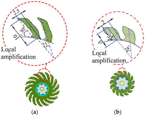
Figure 5.
Outline structure and dimension diagram of fingers of main and secondary clamping wheel: (a) Main wheel finger size; (b) secondary wheel finger size.
2.3.6. Seed Picking Angle
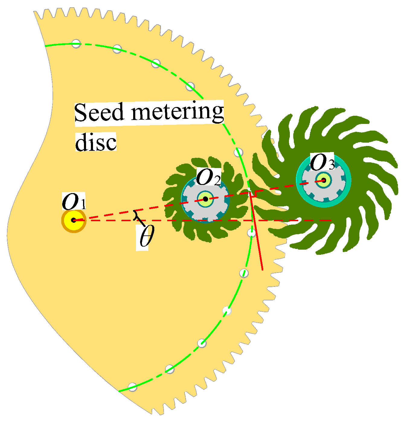
The main and the secondary clamping wheels are the core working parts of the seeding mechanism, which cooperate with each other to realize clamping, conveying, and seeding. In order to make the clamping wheel grip corn seeds effectively, it is necessary to determine the appropriate inoculation angle, that is, the included angle between the connecting line between the main clamping wheel and the secondary clamping wheel shaft and the horizontal plane. This angle should meet the following conditions. When the corn seeds are transported from the hole of the seed disc to the port of the inoculation mechanism, the seeds can stably and accurately enter the spiral clamping position between the main clamping wheel and the secondary clamping wheel and will not deviate. In this case, the inoculation mechanism can make the clamping wheel have a good screw-clamping effect on the corn seeds. In order to achieve this goal, the geometric relationship can be used to deduce that when the center line of the main clamping wheel and the secondary clamping wheel are perpendicular to the tangent of the intersection point of the center of the die hole, the included angle between the straight line and the horizontal plane is the best inoculation angle. That is, when the axes O2 and O3 of the main and secondary clamping wheels are three points and one line with the axis O1 of the seed disc, θ is the angle between the straight line and the horizontal plane, as shown in Figure 6. This angle parameter needs to be further studied through high-speed videography tests.
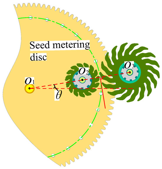
Figure 6.
Location diagram of main and secondary clamping wheels and seed disc.
2.4. Acquisition and Analysis of Seed Displacement Trajectory Based on High-Speed Videography
2.4.1. Experimental Conditions and Materials
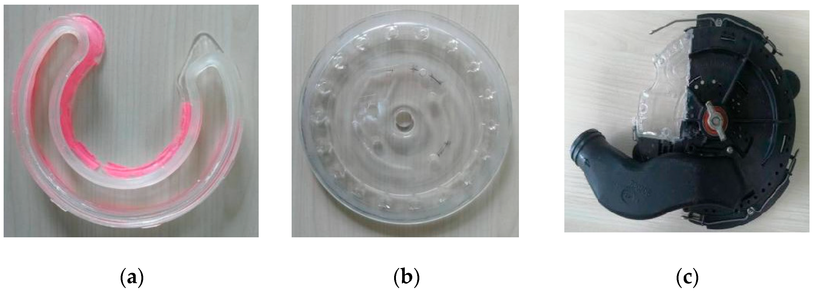
A precision seed metering tool for air suction was used in the experimental setup. The seed metering device’s shell, sealing chamber, and seed disc were all made transparent using transparent 3D printing technology to make it easier to monitor the clamping wheel’s seed-picking status (Figure 7). The DimaxCS 3 high-speed camera, sourced from PCO.DIMAX GmbH in Kelheim, Bayern, Germany, and its supporting PC, sourced from Hewlett-Packard (HP) in Palo Alto, CA, USA, were used.
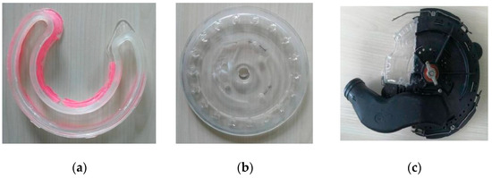
Figure 7.
Transparent seed metering device components: (a) Sealing ring; (b) seed disc; (c) shell.
The high-speed digital videography was set to 600 frames in order to obtain a resolution of the seed displacement trajectory graph suitable for this study when the seed is received at high speed—1920 × 1440 pixels were chosen as the image size. The videography was positioned with the transparent shell of the seed-receiving mechanism in line with it and at the same horizontal height as the seed-receiving mechanism. Figure 8 depicts the test bench that was built in this manner. The seed type selected in the experiment was Demiya No. 1, characterized by a yellow hue and a semi-horseshoe shape. It has a thousand kernel weight of 286.3 g and a moisture content of 13.4%. The negative blower pressure used during the test was 7 kPa.
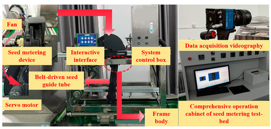
Figure 8.
High-speed videography seed-receiving test bench.
2.4.2. Experimental Method
During the process of measuring seed trajectories, the rotational speed and angle of the clamping wheel were adjusted to the experimentally specified values. The camera captured and stored the seed trajectory images in real-time on the computer. After the experiment, these images were saved as a .avi format video file. The TEMA Classic control software was utilized to track the seeds within the video file, extracting the coordinates of the center of mass of corn seeds from different frames. Subsequently, displacement trajectories of seeds under various conditions were plotted. During data collection, the seed disc rotates at the speeds of 39, 42, 47, 50, and 53 r·min−1, which is equivalent to the planting speeds of 12, 13, 14, 15, and 16 km/h, respectively. These specific rotational and corresponding planting speeds were determined through a series of pre-experiments prior to the formal experiment. The pre-experiments aimed to explore different speed settings to identify the ones that could comprehensively reflect the performance of the seed-guiding device under various working conditions, thus ensuring the validity and representativeness of the subsequent data collection. Repeat three times for each experimental group.
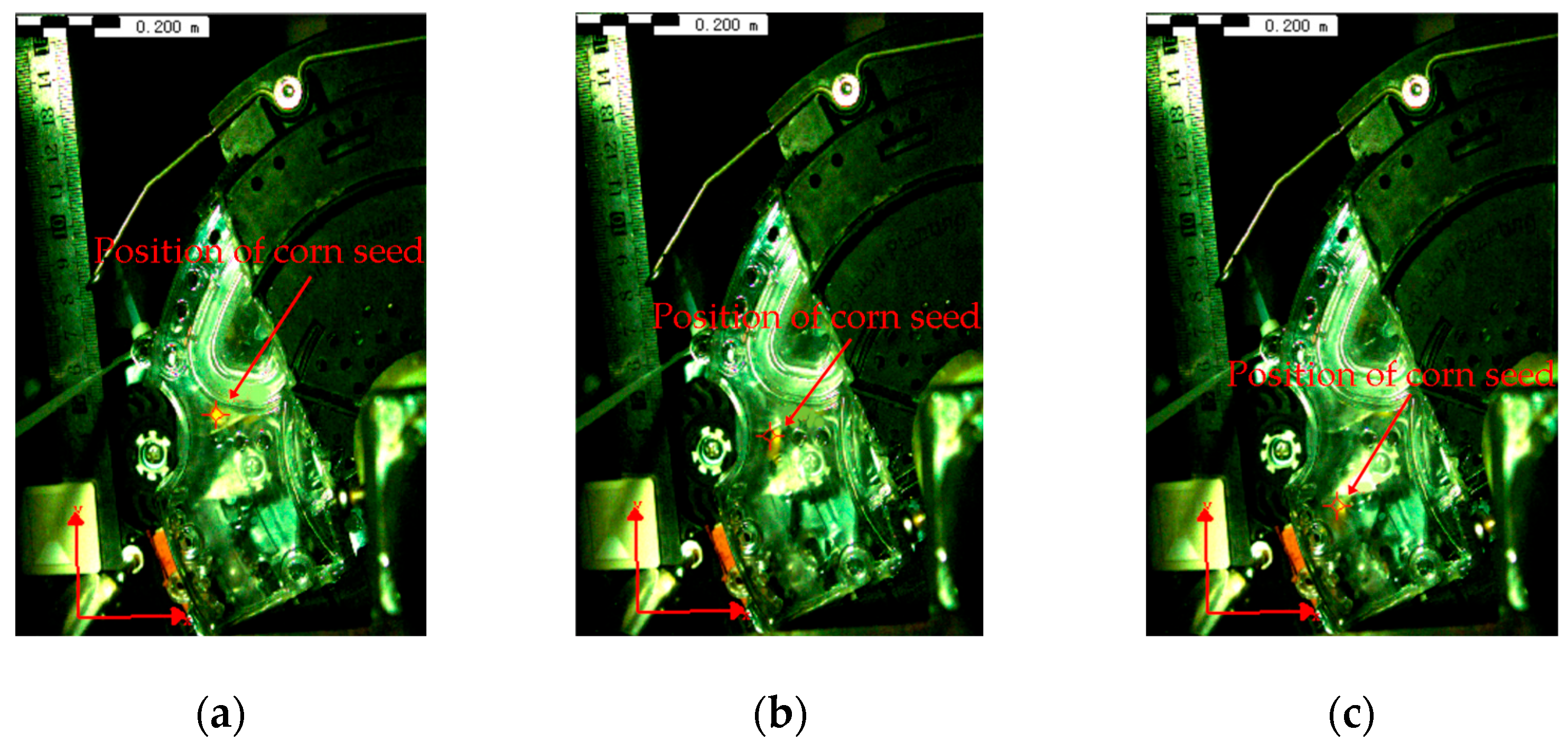
Figure 9 illustrates the high-speed videography’s capture of the clamping wheel’s actual impact on the seed clamping, transporting, and discharging.
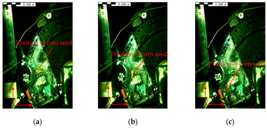
Figure 9.
Seed-receiving process diagram under high-speed videography: (a) Clamping seed; (b) transporting seed; (c) discharging seed.
3. Results and Discussion
3.1. Effect of Clamping Wheel Speed on Corn Seed Speed and Displacement Trajectory
3.1.1. Effect of Clamping Wheel Speed on Corn Seed Speed
The speed of the corn seed can be directly impacted by changing the clamping wheel’s speed. Within a certain range, as the clamping wheel speed rises, the seed’s linear speed rises as well, increasing the seed’s overall speed. Higher speed is beneficial to shorten the time when seeds fall into the seed-conveying belt cavity, but it will increase the collision degree between seeds and the seed-conveying belt and reduce the stability of seeds in the guide transportation. Therefore, studying the trend of seed speed change under different clamping wheel speeds is of great significance in improving the seed-receiving performance of the clamping wheel. To mitigate the collisions between the clamping wheel and the seed and ensure that the clamping wheel has a seed-receiving effect, the range of clamping wheel speed change was determined to be 500–620 r·min−1, so high-speed videography tests were conducted with clamping wheel speeds of 500, 560, and 620 r·min−1, respectively. Figure 10 is the schematic diagram of the broken line change in seed speed under different clamping wheel speeds obtained by the data acquisition system.
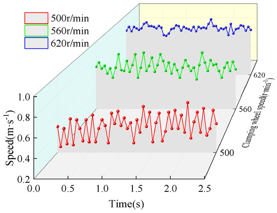
Figure 10.
Impact of varying clamping wheel speeds on seed speed.
As can be seen from Figure 10, with the increase in the rotation speed of the clamping wheel, the movement speed of corn seeds shows an overall increasing trend. When the speed of the clamping wheel is 500 r·min−1, the movement speed of the seeds fluctuates greatly. With the increase in clamping wheel speed to 560 r·min−1, the fluctuation of seed movement speed is further reduced. However, when the rotation speed of the clamping wheel is increased to 620 r·min−1, the fluctuation of the seed movement speed tends to be stable. According to the data change rules, the slower the clamping wheel speed and the linear speed are, the smaller the seed motion speed. This results in significant fluctuations in seed velocity, diminishing the stability of the seed reception process and reducing the inertial force of the clamping wheel on the seed. The faster the clamping wheel spins, the faster it moves linearly, which causes the seed to move faster. As the clamping wheel’s inertial force increases on the seed, the seed speed change becomes more stable. Therefore, in the follow-up study, the speed of corn seeds can be changed by changing the rotation speed of the clamping wheel, which provides the experimental basis for determining the use data of the rotary clamping seed-receiving mechanism.
3.1.2. Effect of Clamping Wheel Speed on Corn Seed Displacement Trajectory
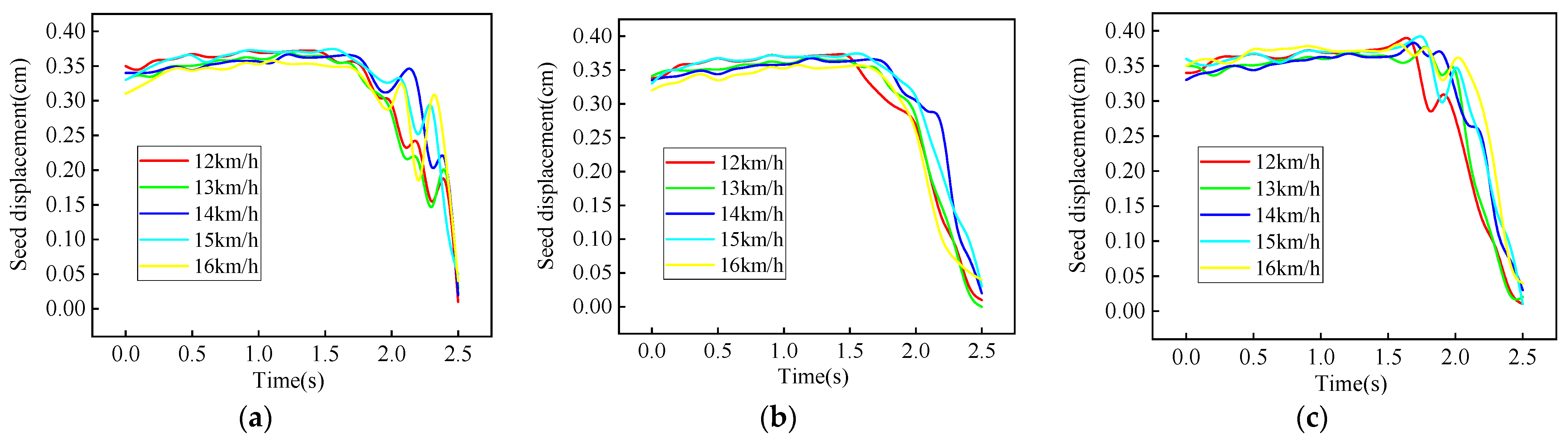
By using the image target tracking technology in high-speed videography, the coordinate values of the seeds in each frame picture can be recorded in Excel 2018 software, and the seed displacement trajectory can be obtained. Figure 11 depicts the displacement trajectories of five groups of seeds at speeds of 500, 560, and 620 r·min−1 for the clamping wheels, respectively.
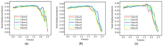
Figure 11.
Effect of clamping wheel speed on the displacement trajectory of seeds: (a) Displacement trajectory of seeds at a clamping wheel speed of 500 r·min−1; (b) displacement trajectory of seeds at a clamping wheel speed of 560 r·min−1; (c) displacement trajectory of seeds at a clamping wheel speed of 620 r·min−1.
As seen in Figure 11, the seed moves with the seed disc in the time period of 0–1.5 s, and the seed displacement trajectory changes at the moment of 1.5 s. This turning point is the seed being received, so 1.5–2.5 s is the seed-receiving stage. Figure 11a shows that under the condition of clamping wheel speed at 500 r·min−1, the seed displacement trajectory fluctuates up and down in 1.5–2.5 s, indicating that the seed is very unstable in the receiving process. Then, the speed of the clamping wheel was adjusted by the governor to 560 r·min−1; the seed displacement trajectory is relatively smooth, indicating that the seed is smooth in the receiving process. With an increase in clamping wheel speed to 620 r·min−1, the seed displacement trajectory fluctuates up and down around 1.5 s, which indicates that the clamping wheel speed is too high and will have an impact effect on the seed. In summary, when the clamping wheel speed is 560 r·min−1, the seed-receiving effect is the best, and the seed displacement trajectory is the smoothest.
3.2. Effect of Seed-Receiving Angle on Corn Seed Speed and Displacement Trajectory
3.2.1. Effect of Seed-Receiving Angle on Corn Seed Speed
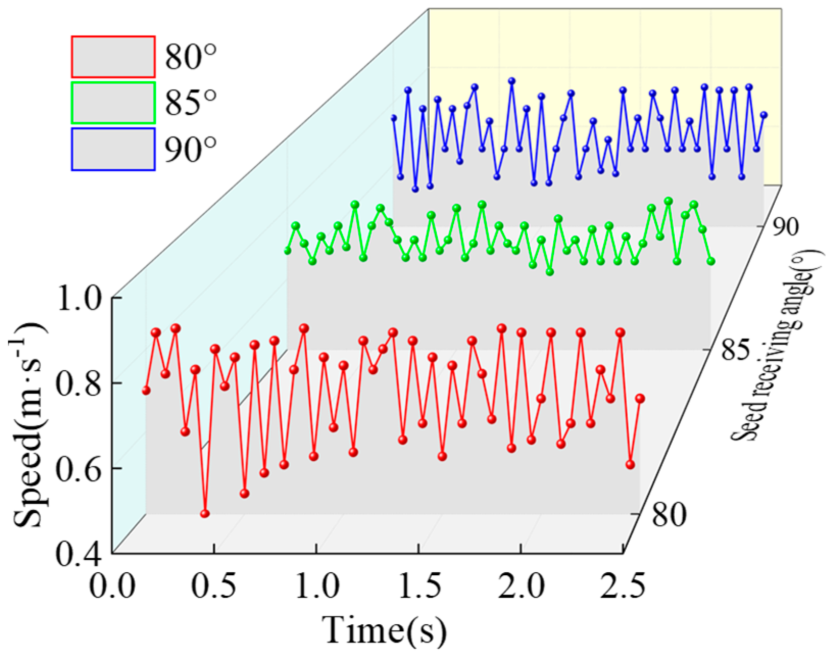
In order to explore the trend of corn seed speed change under different seed-receiving angles, the clamping wheel speed was adjusted to 560 r·min−1. To align with the practical demands of the sowing process and consider the seed reception efficacy of the clamping wheel, the range of seed-receiving angle change in the clamping wheel was determined to be 80–90°. Therefore, high-speed videography tests were conducted with seed-receiving angles of 80°, 85°, and 90°, respectively. Figure 12 shows the variation law of seed speed at different seed-receiving angles obtained by the post-processing module of high-speed videography.
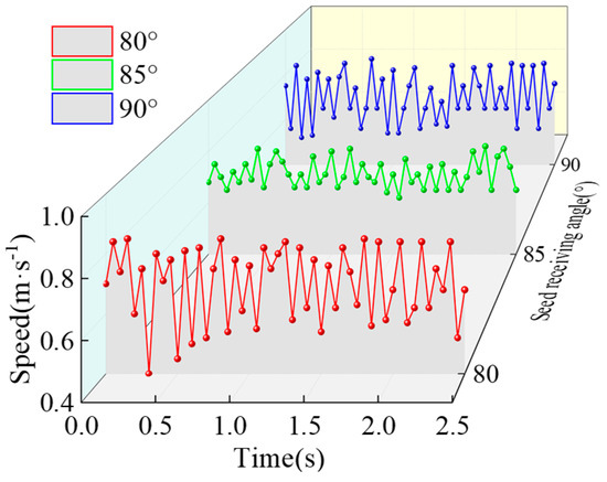
Figure 12.
Impact of varying seed-receiving angles on seed speed.
From Figure 12, it can be calculated that the seed’s average speed is 0.7 m·s−1, which is not obviously affected by the seed-receiving angle, but the fluctuation of speed value is significantly affected. The seed motion speed fluctuates greatly when the seed-receiving angle is 80° or 90°; however, when the seed-receiving angle is 85°, the seed motion speed fluctuates fairly smoothly. By examining the data change rules, it can be determined that a smaller seed-receiving angle will cause the seed to contact the secondary clamping wheel first, producing an unbalanced force that will reduce the stability of the seed motion speed; a larger seed-receiving angle will cause the seed to contact the main clamping wheel first, creating a problem that is similar to the one described above. Therefore, a more stable seed motion speed can be achieved by altering the seed-receiving angle.
3.2.2. Effect of Seed-Receiving Angle on Corn Seed Displacement Trajectory
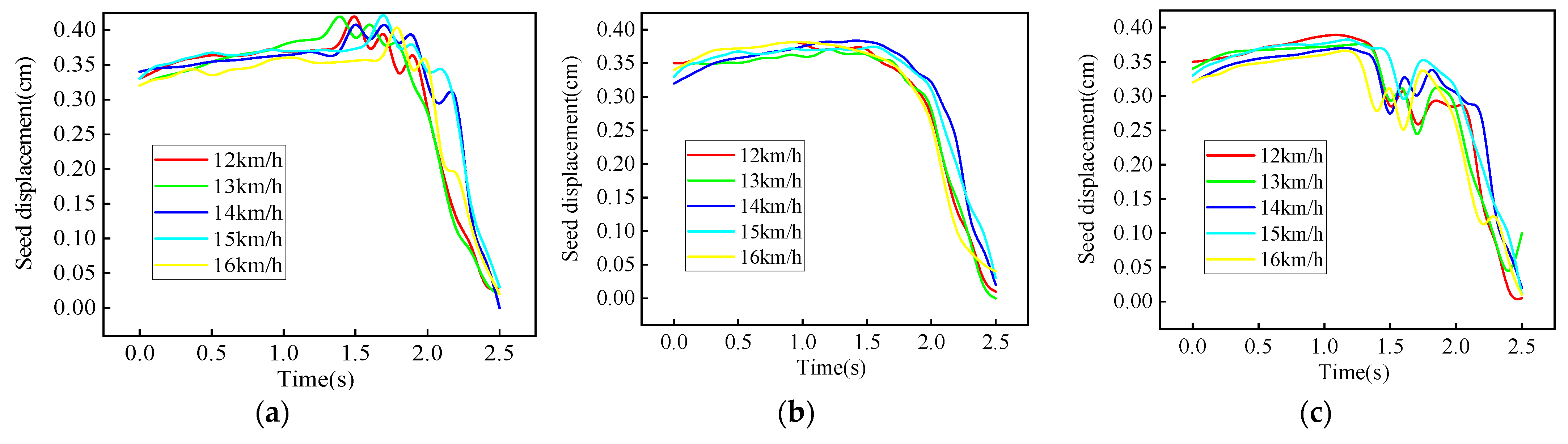
By using the image target tracking technology in high-speed videography, the coordinate values of the seeds in each frame picture can be recorded in Excel software, and the seed displacement trajectory can be obtained. Figure 13 depicts the seeds’ displacement trajectories at sowing speeds of 12 to 16 km/h and seed-receiving angles of 80°, 85°, and 90°, respectively.
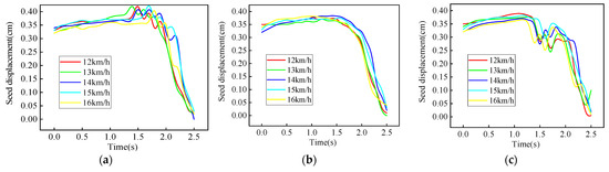
Figure 13.
Effect of seed-receiving angle on the displacement trajectory of seeds: (a) Displacement trajectory of seeds at a seed-receiving angle of 80°; (b) displacement trajectory of seeds at a seed-receiving angle of 85°; (c) displacement trajectory of seeds at a seed-receiving angle of 90°.
As seen in Figure 13, the seed moves with the seed disc between 0 and 1.5 s, and at 1.5 s, the seed displacement trajectory changes. Additionally, 1.5–2.5 s is the seed-receiving stage, and this turning point is when the seed is received. When the seed-receiving angle is 80°, Figure 13a demonstrates that the seed displacement trajectory fluctuates upward in 1.5–2.5 s, indicating that the seed is out of balance in force and strikes the secondary clamping wheel first. The seed displacement trajectory fluctuates downward in 1.5–2.5 s when the seed-receiving angle is 90°, indicating that the seed is out of balance in terms of force and first collides with the main clamping wheel. When the seed-receiving angle is 85°, the displacement trajectory of the seed in 1.5–2.5 s is relatively smooth, indicating that the seed was received smoothly. In conclusion, the seed displacement trajectory is smoothest when the seed-receiving angle is 85°.
3.3. Verification Test
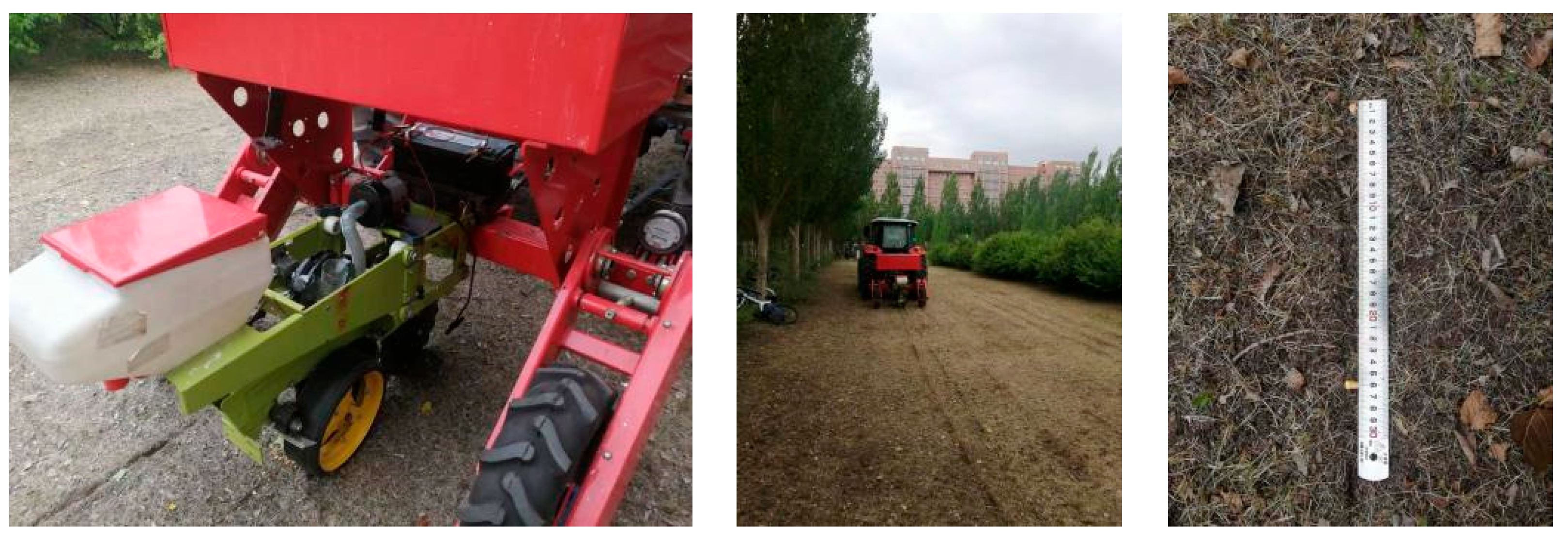
To validate the outcomes of the high-speed videography examination, a field trial was executed. The tractor Aike MF2204, manufactured by AGCO (Changzhou) Agricultural Machinery Co., Ltd. in Changzhou, China, is selected as the traction machine, and the air-suction corn precision seed metering device and the belt-driven seed guide tube are hung on the DEBONT 1405 no-tillage precision seeder unit of Debon Dawei, which can complete the work of straw cutting, ditching and soil covering at one time. The test variables consisted of the clamping wheel speed and seed-receiving angle, while the plant spacing compliance rate, repeated sowing rate, and missed sowing rate of the belt-driven seed guide tube served as the performance evaluation metrics for the field verification experiment [28,29]. The test process is shown in Figure 14.

Figure 14.
Field experiment.
Each group underwent three repetitions, and the test outcome was determined using the statistical processing data’s average value, as shown in Figure 15.
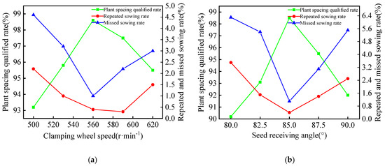
Figure 15.
Line chart of sowing field test data: (a) Impact of clamping wheel speed on sowing indicators; (b) impact of seed-receiving angle on sowing indicators.
As observed in Figure 15a, with the rise in clamping wheel speed, the plant spacing compliance rate initially ascends before declining, and the repeated-missed sowing rate decreases first and then increases, which is consistent with the change rule of seed speed and trajectory under different clamping wheel speeds in the high-speed videography. As depicted in Figure 15b, with the augmentation in seed-receiving angle, the plant spacing qualified rate increases first and then decreases, and the repeated-missed sowing rate decreases first and then increases, which is consistent with the change rule of seed speed and trajectory under different seed-receiving angles of the clamping wheel in the high-speed videography.
4. Conclusions
(1) The clamping wheel speed and seed-receiving angle were established as the primary test factors after structural optimization and analysis of the seed-receiving mechanism for the belt-driven seed guide tube.
(2) Under various clamping wheel speeds and seed-receiving angles, the speed change trend and displacement trajectory of the seeds were examined using high-speed videography technology. The results showed that the displacement trajectory was smoother at a clamping wheel speed of 560 r·min−1; the seed speed exhibited improved stability and reduced fluctuation. The displacement trajectory was also smoother when the seed-receiving angle was 85°.
(3) The results of the field verification tests revealed that the field test outcomes largely matched the change rule of the high-speed videography test data, allowing the high-speed videography technology to be used to examine the operation of the belt-driven seed guide tube’s seed-receiving mechanism.
Author Contributions
Conceptualization, C.M. and Z.Z.; data curation, X.C., Y.T. and N.S.; formal analysis, X.Y. and Y.X.; funding acquisition, Z.Z.; investigation, C.M. and Z.Z.; methodology, C.M. and Z.Z.; project administration, Z.Z. and Y.X.; resources, X.C. and Y.T.; software, C.M.; supervision, X.C. and C.M.; validation, X.Y., and Y.X.; visualization, C.M. and N.S.; writing—original draft, C.M. and Z.Z.; writing—review and editing, C.M. and X.C. All authors have read and agreed to the published version of the manuscript.
Funding
This research was funded by the Program for Innovative Research Team in SDAEU, grant number sgykycxtd2020-03.
Institutional Review Board Statement
Not applicable.
Data Availability Statement
The data presented in this study are available on request from the corresponding author (The data are not publicly available due to privacy restrictions).
Conflicts of Interest
The authors declare no conflicts of interest.
References
- Liu, J.; Tian, Q.; Huang, Y.; Du, L.; Wang, L. Extraction of the corn planting area based on multi-temporal HJ-1 satellite data. In Proceedings of the 2011 19th International Conference on Geoinformatics, Shanghai, China, 24–26 June 2011; p. 4. [Google Scholar] [CrossRef]
- Virk, S.S.; Fulton, J.P.; Porter, W.M.; Pate, G.L. Row-crop planter performance to support variable-rate seeding of maize. Precis. Agric. 2020, 21, 603–619. [Google Scholar] [CrossRef]
- Lobell, D.B.; Schlenker, W.; Costa-Roberts, J. Climate trends and global crop production since 1980. Science 2011, 333, 616–620. [Google Scholar] [CrossRef] [PubMed]
- Tigchelaar, M.; Battisti, D.S.; Naylor, R.L.; Ray, D.K. Future warming increases probability of globally synchronized maize production shocks. Proc. Nat. Acad. Sci. USA 2018, 115, 6644–6649. [Google Scholar] [CrossRef] [PubMed]
- Erenstein, O.; Jaleta, M.; Sonder, K.; Mottaleb, K.; Prasanna, B.M. Global maize production, consumption and trade: Trends and R&D implications. Food Secur. 2022, 14, 1295–1319. [Google Scholar] [CrossRef]
- Grote, U.; Fasse, A.; Nguyen, T.T.; Erenstein, O. Food security and the dynamics of wheat and maize value chains in Africa and Asia. Front. Sustain. Food Syst. 2021, 4, 617009. [Google Scholar] [CrossRef]
- Wang, S.; Yi, S.; Zhao, B.; Li, Y.; Wang, G.; Li, S.; Sun, W. Photoelectric sensor-based belt-type high-speed seed guiding device performance monitoring method and system. Comput. Electron. Agric. 2024, 227, 109489. [Google Scholar] [CrossRef]
- Liu, Z.; Xia, J.; Hu, M.; Du, J.; Luo, C.; Zheng, K. Design and analysis of a performance monitoring system for a seed metering device based on pulse width recognition. PLoS ONE 2021, 16, e0261593. [Google Scholar] [CrossRef]
- Tang, H.; Xu, F.; Guan, T.; Xu, C.; Wang, J. Design and test of a pneumatic type of high-speed maize precision seed metering device. Comput. Electron. Agric. 2023, 211, 107997. [Google Scholar] [CrossRef]
- Zhang, J.; Hou, Y.; Ji, W.; Zheng, P.; Yan, S.; Hou, S.; Cai, C. Evaluation of a Real-Time Monitoring and Management System of Soybean Precision Seed Metering Devices. Agronomy 2023, 13, 541. [Google Scholar] [CrossRef]
- Badua, S.A.; Sharda, A.; Strasser, R.; Ciampitti, I. Ground speed and planter downforce influence on corn seed spacing and depth. Trans. ASABE 2021, 22, 1154–1170. [Google Scholar] [CrossRef]
- Chen, X.; Zhong, L. Design and test on belt-type seed delivery of air-suction metering device. Trans. CSAE 2012, 28, 8–15. [Google Scholar] [CrossRef]
- Ma, C.; Yi, S.; Tao, G.; Li, Y.; Wang, S.; Wang, G.; Gao, F. Research on receiving seeds performance of belt-type high-speed corn seed guiding device based on discrete element method. Agriculture 2023, 13, 1085. [Google Scholar] [CrossRef]
- Tang, H.; Xu, C.; Wang, Z.; Wang, Q.; Wang, J. Optimized design, monitoring system development and experiment for a long-belt finger-clip precision corn seed metering device. Front. Plant Sci. 2022, 13, 814747. [Google Scholar] [CrossRef]
- Lü, J.; Yang, Y.; Li, Z.; Tian, Z.; Shang, Q.; Wu, J.E. Design and experiment of cup-belt type potato seed-metering device. Trans. CSAE 2016, 32, 17–25. [Google Scholar] [CrossRef]
- Kocher, M.F.; Coleman, J.M.; Smith, J.A.; Kachman, S.D. Corn seed spacing uniformity as affected by seed tube condition. Appl. Eng. Agric. 2011, 27, 177–183. [Google Scholar] [CrossRef]
- Karayel, D.; Šarauskis, E.; Aktaş, A. Design and Experiment of a Helicoidal Seed Tube to Improve Seed Distribution Uniformity of Seed Drills. Processes 2022, 10, 1271. [Google Scholar] [CrossRef]
- Savi, D.; Kmiecik, L.L.; Neto, L.S.; da Silva, T.X.; Jasper, S.P. Influence of seed tube curvature on seed longitudinal distribution. Eng. Agríc. 2020, 40, 732–739. [Google Scholar] [CrossRef]
- Wang, B.; Liao, Q.; Wang, L.; Shu, C.; Cao, M.; Du, W. Design and test of air-assisted seed-guiding device of precision hill-seeding centralized seed-metering device for sesame. Agriculture 2021, 13, 393. [Google Scholar] [CrossRef]
- Li, Y.; Zhou, W.; Ma, C.; Feng, Z.; Wang, J.; Yi, S.; Wang, S. Design and optimization of the seed conveying system for belt-type high-speed corn seed guiding device. Int. J. Agric. Biol. Eng. 2024, 17, 123–131. [Google Scholar] [CrossRef]
- Zhu, H.; Zhang, S.; Wang, W.; Lv, H.; Chen, Y.; Zhou, L.; Li, M.; Zhao, J. Design and Testing of Soybean Double-Row Seed-Metering Device with Double-Beveled Seed Guide Groove. Agriculture 2024, 14, 1595. [Google Scholar] [CrossRef]
- Li, H.; Liu, H.; Zhou, J.; Wei, G.; Shi, S.; Zhang, X.; Zhang, R.; Zhu, H.; He, T. Development and first results of a no-till pneumatic seeder for maize precise sowing in Huang-Huai-Hai plain of China. Agriculture 2021, 11, 1023. [Google Scholar] [CrossRef]
- Wen, W.; Wang, Y.; Wu, S.; Liu, K.; Gu, S.; Guo, X. 3D phytomer-based geometric modelling method for plants—The case of maize. AoB Plants 2021, 13, plab055. [Google Scholar] [CrossRef]
- Tang, H.; Xu, C.; Jiang, Y.; Wang, J.; Wang, Z.; Tian, L. Evaluation of physical characteristics of typical maize seeds in a cold area of north China based on principal component analysis. Processes 2021, 9, 1167. [Google Scholar] [CrossRef]
- Wang, B.; Zhang, Y.; Hao, B.; Xu, X.; Zhao, Z.; Wang, Z.; Xue, Q. Grain Yield and Water Use Efficiency in Extremely-Late Sown Winter Wheat Cultivars under Two Irrigation Regimes in the North China Plain. PLoS ONE 2016, 11, e0153695. [Google Scholar] [CrossRef]
- Guo, H.; Cao, Y.; Song, W.; Zhang, J.; Wang, C.; Wang, C.; Yang, F.; Zhu, L. Design and simulation of a garlic seed metering mechanism. Agriculture 2021, 11, 1239. [Google Scholar] [CrossRef]
- Ding, Y.; Li, H.; Gao, J.; Yu, H.; Wang, Y.; Feng, D. Parameter Optimization of Finger Clip Plate Garlic Seed-Metering Device. Agriculture 2023, 13, 2071. [Google Scholar] [CrossRef]
- Cui, X.; Wang, Z.; Zhuang, T.; Sun, J.; Song, Y. Improving wheat seedling quality through deep ploughing and soil compaction at sowing in lime concretion black soil. PLoS ONE 2023, 18, e0288459. [Google Scholar] [CrossRef]
- Bai, S.; Yuan, Y.; Niu, K.; Shi, Z.; Zhou, L.; Zhao, B.; Wei, L.; Liu, L.; Zheng, Y.; An, S.; et al. Design and experiment of a sowing quality monitoring system of cotton precision hill-drop planters. Agriculture 2022, 12, 1117. [Google Scholar] [CrossRef]


Disclaimer/Publisher’s Note: The statements, opinions and data contained in all publications are solely those of the individual author(s) and contributor(s) and not of MDPI and/or the editor(s). MDPI and/or the editor(s) disclaim responsibility for any injury to people or property resulting from any ideas, methods, instructions or products referred to in the content. |
© 2025 by the authors. Licensee MDPI, Basel, Switzerland. This article is an open access article distributed under the terms and conditions of the Creative Commons Attribution (CC BY) license (https://creativecommons.org/licenses/by/4.0/).