Article

Discrete Element-Based Design of a High-Speed Rotary Tiller for Saline-Alkali Land and Verification of Optimal Tillage Parameters

1
College of Mechanical and Electrical Engineering, Qingdao Agricultural University, Qingdao 266109, China
2
Yellow River Delta Intelligent Agricultural Machinery Equipment Industry Academy, Dongying 257300, China
3
Academician Workstation of Agricultural High-tech Industrial Area of the Yellow River Delta, National Center of Technology Innovation for Comprehensive Utilization of Saline-Alkali Land, Dongying 257345, China
4
Qingdao Agricultural Machinery Production and Distribution Association, Qingdao 266109, China
5
College of Mechanical and Electronic Engineering, Shandong Agricultural University, Taian 271018, China
*
Authors to whom correspondence should be addressed.
Agriculture 2025, 15(3), 269; https://doi.org/10.3390/agriculture15030269
Submission received: 23 December 2024 / Revised: 20 January 2025 / Accepted: 24 January 2025 / Published: 26 January 2025
(This article belongs to the Section Agricultural Technology)

Abstract

:
Aiming at the saline soil in Binhai New Area, which is solid and sclerotic, and addressing the problem of poor quality and low efficiency of traditional rotary tillage, this research designed a high-speed rotary tiller that can realize the high-speed rotation of knife rollers to cut. The average operating speed is higher than that of the ordinary rotary tiller. We analyzed the rotary tiller operating conditions and rotary tiller knife cutting process and conducted a movement trajectory theoretical analysis to determine the rotary tiller’s high-speed operating speed relationship. The working process of a high-speed rotary tiller was simulated using EDEM software. The experimental indicators included the soil-crushing rate and surface smoothness after tilling. The experimental factors included the forward speed of the machine, the rotational speed of the blade roller, and the tilling depth. An orthogonal experiment was performed to establish regression equations for the soil-crushing rate and surface smoothness. Using Design-Expert analysis software, we obtained the following optimal combination of parameters: a knife roller speed at 310 r/min, tillage depth of 13.2 cm, and machine forward speed of 4.8 km/h. At this time, the simulation values of the soil fragmentation rate and surface flatness were 90.6% and 18.2 mm, respectively. When determining the optimal knife roller speed of 310 r/min, a transient structural simulation under the mesh bevel gear transient was conducted. The simulation analysis showed that the maximum equivalent stress value was 584.57 MPa, which was smaller than the permissible stress of 695.8 MPa, meeting the bevel gear meshing strength requirements. Under the optimal combination determined by a field comparison test, the results show that the values of the high-speed rotary tiller operation after the soil-breaking rate, tillage depth, the tillage depth stability coefficient, and vegetation cover were 89.3%, 14.2 cm, 92.8%, and 90.3%. The land surface flatness was 16.4 mm, which is superior to the ordinary rotary tiller operation effects, meeting the agronomic requirements for pre-sowing land preparation for peanuts in the saline land of Binhai New Area.

1. Introduction

Rotary plowing is an important part of crop cultivation, and the quality of its operation directly affects the growth and yield of crops in the following season [1]. Rotary plows can efficiently break and turn the soil, improve the physical properties of the soil, increase soil permeability and water retention capacity, and—at the same time—have a beneficial effect on crop residue breakage and burial [2,3,4,5]. The saline land in Binhai New Area is mainly plowed using a rotary tiller to build up the seedbed before planting peanuts. The soil in this area has a high degree of salinity and is hard and crusty, leading to poor crushing effects, requiring rotary plowing to prepare the seedbed required for sowing, seriously affecting the efficiency of rotary plowing operations. Therefore, developing rotary plowing machines that can improve the efficiency of land preparation and the soil-breaking effect in saline soils is important for improving the quality and efficiency of rotary plowing operations in saline soil.
Research studies conducted by scholars at home and abroad mainly focus on soil disturbance and displacement changes after plowing. There is even less research on saline rotary tiller operation effects and saline rotary tiller discrete element model operation analysis. It is difficult to come up with the actual saline rotary tiller operation effect, so it is necessary to improve the design of the rotary tiller for the seedbed preparation requirements of saline land.
Among them, Zhao et al. designed a dual-axis-stratified rotary tiller for saline and alkaline land, with positive rotation on the front axle and reverse rotation on the rear axle, to address the problems of poor straw mulching performance and low soil fragmentation rate in traditional rotary tillers for saline and alkaline land. They carried out tests using the method of discrete meta-modeling and field tests, which showed that the dual-axis-stratified rotary tiller for saline and alkaline land had improved the soil fragmentation rate and the effect of straw mulching. This design could provide a good reference for the R&D of cultivation and preparation equipment in saline and alkaline land [6]. Li et al. conducted tests on soil disturbance and the distribution of water and salinity in saline and alkaline land, using different tillage depths of traditional rotary tillers and vertical rotary tillers. The test results showed that a deep vertical rotary tiller could cut off the soil capillaries, weaken the evaporation of soil water, and effectively control the salinization of the soil [7]. Upadhyay et al. conducted performance tests on three kinds of offset disc harrows at different forward speeds. The test results showed that increasing the forward speed and the rotation speed of the harrows had good effects on crop stubble burial efficiency and soil breakage [8]. Salokhe et al. experimented with different forward speeds of a reverse rotary tiller in a clay soil environment; the results showed that the forward speed of the rotary tiller decreased soil adhesion when it increased [9]. Jafar Habibi Asl, Surrender Singh, and colleagues conducted a study on rotary tillage blades by optimizing three existing forms—C-shaped, L-shaped, and RC-shaped rotary tillage blades—for laboratory soil slot experiments to determine the relationship between the structural parameters of the various blades and the forward speed, rotational speed, speed ratio, and the distance of the soil cut into the soil [10]. Tian et al. studied the power consumption, soil-breaking rate, and plowing depth qualification rate of rototiller as test indexes, as well as the rotary roll rotation speed, unit advance speed, and rotary tiller blade arrangement as test factors. Finally, it was determined that the unit’s advance speed had the greatest impact on the operation performance of the rotary tiller, followed by the rotary roll speed and the rotary tiller blade arrangement [11]. Zheng et al. designed a rotary plowing knife roller with a combination of long and short knives, according to the distribution characteristics of soil compactness after the operation of a deep pine rotary plowing-combined machine; the experimental results showed that the knife roller design reduces the vibration of the machine tool and improves the ground surface flatness [12].
In terms of the design of the rotary tillage knife axis, soil throwing, and soil-breaking using a rotary tillage knife, Yang et al. designed a combined rotary tillage knife and telescopic rod cutter roller to achieve the effective burial of corn stalks, and installed four rotary tillage knives arranged at equal spiral elevation angles in the same soil plot [13]. Zhang et al. developed a six-head spiral straw return plowing machine knife roller, rotary plowing knives using a four-head helix arrangement, and a secondary cutter using a two-head helix arrangement, although the test showed that the knife roller speed and operating speed had significant effects on the crushed soil [14]. Zheng et al. designed an axial soil-leveling cutter roller with a gradual spiral lift angle, which increased the inward conveying amount of accumulated soil on both sides of the cage of the combined trenching rotary tillage machine and improved the surface flatness and soil axial distribution uniformity [15]. Matin et al. tested rotary tiller blade rollers at different speeds, showing that the increased speed of the blade rollers increased the soil-breaking effect and was not affected by the blade geometry [16].
In order to improve the efficiency of rotary plowing in saline land, this paper presents the design of a high-speed rotary tiller that combines the requirements of peanut planting in the saline agricultural area of Binhai New Area. This paper includes a theoretical analysis of the rotary tiller’s trajectory and soil-cutting operation, design, and the key components of the rotary tiller roller, combined with a discrete element simulation and orthogonal center combination test to obtain the optimal parameter combination of the high-speed rotary tiller and verify the field comparative test, providing a reference for the preparation technology of the peanut seedbed in saline-alkaline land in Binhai New Area.

2. Machine Structure and Working Process

2.1. Complete Machine Structure

As shown in Figure 1, the high-speed rotary tiller structure features a rotary plowing knife roller that is symmetrically mounted on the output shafts of both sides of the gearbox and fixed on the frame. The rotary plowing knives are arranged in a symmetrical helix on the knife axis. The helix angle of adjacent rotary plowing knives on the same helix is 15°. The soil plane has four rotary plowing knives, each separated by an angle of 90 degrees, and the rotation direction of the knife roll is positive, that is, the rotation direction of the knife roll is consistent with the direction of the tractor.

2.2. Working Process

From the working process diagram of the high-speed rotary tiller in Figure 2—when the rotary tiller is working, the front end of the high-speed rotary tiller is connected to the power output shaft of the tractor through the drive shaft. The tractor transmits power to the gear gearbox through the rear output shaft, and the gearbox transmits power decomposition to the rotary tiller cutter roller. In order to adapt to the forward speed of the tractor, the gearbox of the ordinary rotary tiller is designed systematically, so that it can meet the requirements of the high-speed operation of the machine and drive the rotary tiller cutter roller to rotate the soil [16,17,18].
The rotary tillage knife continuously cuts, breaks, mixes, and throws back the soil and straw in the untilled area, gradually dividing the soil into three parts: the waiting area, the tilled area, and the untilled area. The pallet continuously scrapes and breaks the soil in the tilled area, ensuring that the soil in the tilled area forms a fine and flat soil surface along the direction of the rotary tiller.

3. Design of Key Mechanism Parameters

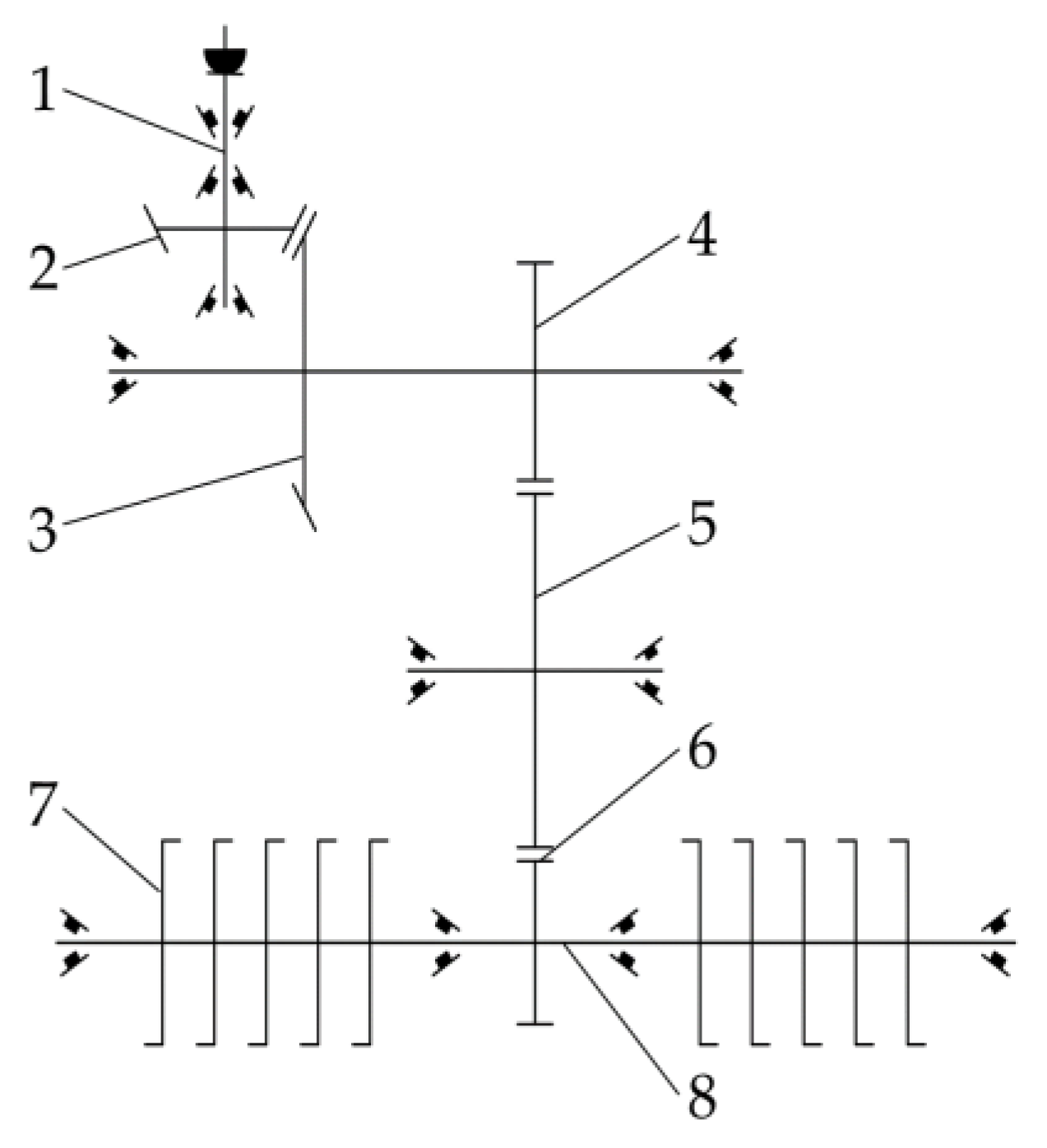
3.1. Drive Train Design

The rotary speed of the rotary cutter plays a vital role in the soil-breaking rate and land surface flatness. In order to meet the requirements of the soil-breaking rate and land surface flatness after rotary plowing in high-speed forward-working conditions, the system design of the rotary tiller gearbox was carried out. The design and analysis of the gearbox ensure that the rotary cutter roller obtains sufficient rotational speed, maintaining the quality of soil processing by the rotary tiller in the state of high-speed forwarding. The gearbox transmission program shown in Figure 3 features shaft 1 as the power input shaft, from the tractor rear output shaft to the small bevel gear 2; small bevel gear 2 and the slave shaft bevel gear 3 mesh to transfer power; spur gear 4 and bevel gear 3 are coaxial, so spur gear 4 and the main shaft spur gear 5 mesh to transfer power; knife roller shaft 5, spur gear 6, and the main shaft spur gear 5 mesh to transfer the power to the knife rollers, driving knife roller rotation.
In order to meet the knife roller speed required for the rotary tiller’s high-speed forward speed, the gearbox structure remains unchanged under the premise of this paper’s systematic design of a high-speed rotary tiller transmission system. The main transmission gear ratio is improved in order to meet the requirements for the high-speed operation of the rotary tiller. The gear ratio in the gearbox is shown in Formula (1), as follows:
i = n i n n o u t = z 2 z 1
where nin is the input shaft speed; nout is the output shaft speed; z2 is the number of teeth on the driven gear; and z1 is the number of teeth on the driven gear.

3.2. Mechanical Analysis and Parameter Design of the Rotary Tiller

The absolute motion of the rotary tiller’s blade in the rotary tiller’s working process involves the synthesis of two kinds of motion—one is the linear motion of the rotary tiller roller when it is pulled forward with the tractor implements, and the other is the circular motion of the rotary tiller blade rotating around the rotary cutter axis in the rotary tillage process. The absolute motion of the rotary tillage knife is synthesized by these two motions, i.e., the trajectory of the tip of the knife is a coswing line [19].
When the radius of the rotation of the blade is R, the angular speed of rotation is ω, the forward speed of the machine is υm, the initial rotation center O of the knife roller is the coordinate origin, the forward direction of the machine is aligned with the x-axis, and the y-axis corresponds to the direction of gravity, establishing the rotary tillage knife coordinate system as shown in Figure 4.
From Figure 4 the parametric equation for the trajectory of the rotary cutter endpoint is given by the following:
x = R c o s ω t + v m t y = R   s i n   ω t
where vm is the forward speed of the machine, m/s; ω is the rotary angular speed of the rotary plow blade, rad/s; and t is the time of blade movement, s.
The speed of motion of the blade endpoint is as follows:
v x = d x / d t = v m R ω   s i n ω t v y = d y / d t = R ω   c o s   ω t
Therefore, the absolute speed of motion at the endpoint of the blade is as follows:
v = v x 2 + v y 2 = v m 2 + R 2 ω 2 2 v m R ω   s i n   ω t
The blade endpoint circumferential velocity is as follows:
v p = R ω
Let λ = vp/vm = /vm, the size of λ has an important effect on the rotary plow knife trajectory and operating conditions, λ refers to the rotary plow speed ratio, which is obtained by bringing it into Equation (6), as follows:
v x = v m R ω   s i n   ω t = v m 1 λ   s i n   ω t
When λ < 1, i.e., vp < vm, no matter what state the rotary plow knife moves to, the horizontal speed of the endpoint of the blade is always the same as the forward direction of the tiller. At this time, the trajectory of the rotary plow knife is a short pendulum line. The rotary plow knife cannot cut the soil backward, leading to the congestion and pushing of the soil, and the rotary tiller cannot work properly.
When λ > 1, the horizontal speed of the blade’s endpoint is opposite to the forward direction of the tiller, and the trajectory of the tiller blade follows a pendulum line. At this time, the tiller blade can cut the soil backward in a normal fashion, allowing the tiller to work normally.
Therefore, the condition that ensures the normal operation of the rototiller is λ > 1, i.e., the circumferential speed is greater than the forward speed of the rototiller.
In order to cut the soil effectively, the trajectory of the rotary tillage knife is a synthesis of the forward and rotary motion and meets the requirements of the cospline [20]. As shown in Figure 5, for the rotary cutter soil-cutting operations, the soil-cutting area S in the working cycle of each rotary tiller includes the curved triangle area S1, surrounded by points x1, x2, and x4; the rectangular area S2, surrounded by points x1, x3, x4, and x5, minus the curved triangle area S3, surrounded by points x2, x3, and x5.
Point x1 is the first entry point in the work cycle of the rotary cutter end, point x3 is the second entry point in the work cycle of the rotary cutter end, and point x2 is the intersection point of the two cuts in the work cycle of the rotary cutter, which cuts down the soil and completes one work cycle. Let the equation of the curve at point x1x2 be f1(x), the equation of the curve at point x2x3 be f2(x), and the area of soil cut by a single rotary cutter S be as follows:
S = S 1 + S 2 S 3 = X 3 X 1 d x R f 1 x d y + H x 2 x 1 x 2 x 3 d x R f 2 x d y
The parametric equation for the soil cut area S during the working cycle of a single rotary tiller can be obtained from Equation (5) as follows:
S = t 2 t 1 R R   s i n ω t v m R   s i n ω t d t + H R   c o s ω t 3 + v m t 3 R   c o s ω t 4 v m t 4 t 4 t 3 v m R   s i n ω t R R   s i n ω t d t
The equation for the moment of passage of the rotary cutter through each endpoint is given by the following:
ω t 1 = a r c s i n 1 H R R   c o s ω t 2 + v m t 2 = 3 π v m 2 ω t 3 = 2 π ω + t 1 t 4 = 3 π ω t 2
The cutting pitch has a greater impact on the quality of rotary tillage knives by breaking up the soil, the plowing depth stability, the flatness of the furrow bottom, and the flatness of the ground surface. The cutting area between two neighboring rotary tillage knives is related to the time and distance at which the blades enter the soil successively during the working cycle [21,22]. The soil-cutting pitch S relational equation is as follows:
S = v m t
The relationship between the moments when the soil cuts intersect during the working cycle of the rotary tiller can be derived as follows:
R   c o s ω t 2 + s z ω t 2 2 π = 3 s z 4
where s is the cut pitch, and z is the number of blades in the same soil plane.
The quality of the rotary plow’s work in the state of the high-speed forward operation has an important relationship with the rotational speed of the knife roller and the number of blades in the same soil plane. According to the agronomy of peanut cultivation in the Yellow River Delta region, in order to improve the structure of the soil tillage layer, increase the soil porosity, and improve the rooting and germination rate of peanuts, when rotary plowing, the best plowing depth of about 10~14 cm is selected. At the same time, to ensure peanut yield, rotary tillage operations need to be performed immediately after the previous crop is harvested. At this time, the soil moisture content is generally in the range of 20~25% or so, and the seriousness of the land plate is significant. To appropriately reduce the pitch of the cut soil to improve the effect of soil crushing, the pitch of the soil, S, cut by the rotary tillage knives takes the value in the range of 6 m~10 cm. The IIT195 rotary tillage knife was selected for this test, which has better slip-cutting performance and anti-weed and straw entanglement characteristics. According to GB T5669-2017 [23]: Rotary Tiller—Rotary Blades and Blade Holders (National Technical Committee for Standardization of Agricultural Machinery: Beijing, China, 2017), the working width is 50 mm, the rotary radius of the knife roller is 195 mm, and the bending angle of the positive cutting surface is 120°. According to GB T5668-2017 [24]: Rotary Tiller (Standardization Administration of China: Beijing, China, 2017), the value of n ranges from 150 to 350 r/min.
Comprehensively analyzing the above, the knife roller speed (150~350 r/min), tillage depth (10~14 cm), and machine forward speed (4~8 km/h) were selected as the performance test factors of the high-speed rotary tiller.

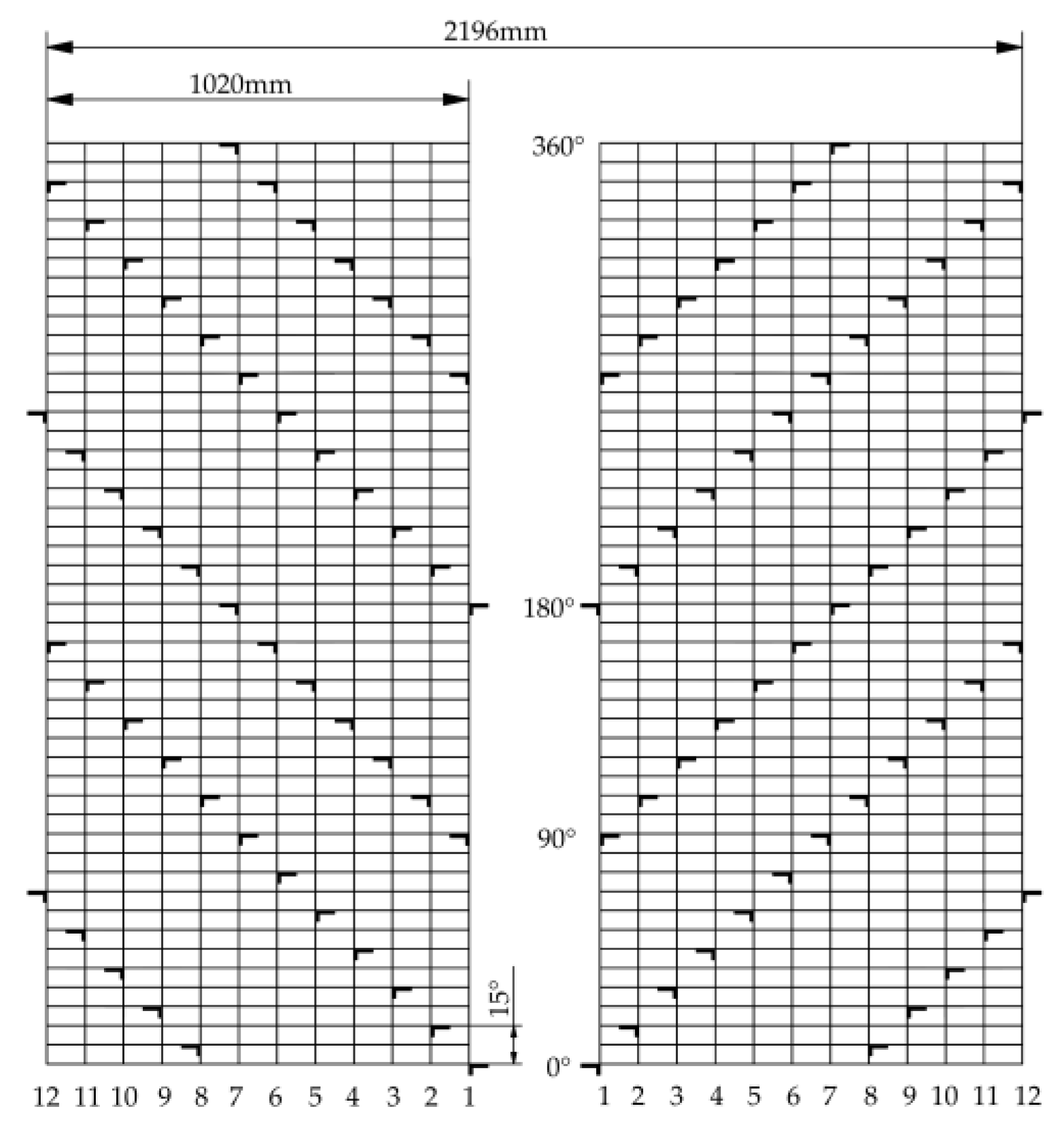
3.3. Analysis of Rotary Cutter Arrangement and Helical Rise Angle

The rotary tillage knife roller is divided into left and right knife rolls, with the gearbox as the reference. The rotary tillage knives are arranged on the knife shaft in a helical way, so the rotary tillage knives are in helical motion during the operation. According to the research, different spiral arrangement angles of rotary plowing knives have different effects on soil disturbance [25]. For this reason, the spiral rise angle and arrangement of rotary knives are determined according to the operational requirements of high-speed rotary tillers.
For large fields, the number of blades in the same installation plane should not be too many, otherwise, the blades will be entangled with the straw, resulting in excessive resistance to rotary plowing and the congestion-blocking phenomenon, ultimately leading to increased rotary plowing power consumption and poor plowing results.
The arrangement of rotary blades on the cutter roll is one of the most important factors affecting the quality of tillage and power consumption.
The rotary tillage speed ratio and cutting pitch are the main indexes used for evaluating the rotary tiller’s operational performance and soil crushing quality. The rotary tillage speed ratio λ is as follows:
λ = R ω v m
where R is the rotary radius of the rotary tiller, mm; ω is the rotary angular speed of the rotary tiller, rad/s.
From Equation (10), the cut-soil pitch is defined as follows:
S = 6000 v m n z = π R 5 λ z
where n is the rotational speed of the knife roller, measured in r/min; and z is the number of rotary knives, one.
Due to λ > 1, usually, the number of rotary tillage knives installed in the same plane is generally z ≥ 2. With the increase in the number of rotary tillage knives, the pitch of the soil cutter is reduced, and the effect of soil crushing is also good, so z = 4, 4 rotary tillage knives are installed uniformly, and the blades are spaced 90° apart from each other.
While the rotary tiller cuts the soil, the end of the blade tears the soil in its vicinity, and the longitudinal mounting distance, b′, of the rotary tiller should be greater than the working width, b, of the rotary tiller [26]. The width of the rotary plow blade operation is shown in Figure 6.
b = b + Δ b
where b′ is the longitudinal installation spacing of the rotary cutter, mm; b is the working width of the rotary cutter, mm; and Δb is the longitudinal adjustment clearance of the adjacent rotary cutter, mm.
Δb is commonly used in the range of 15~20 mm; this paper selected the IIT195 rotary plowing knife with a working width, b, of 50 mm, in order to avoid blade interference; Δb was set to 20 mm.
The total number of blades installed on the rotary cutter rolls is calculated in Equation (17).
Z = 2 × B z / b
where Z′ is the total number of rotary tillage knives; B is the effective length of the unilateral rotary tillage knife roller, mm; and z is the number of rotary tillage knives in the same installation plane, one.
The total working width of the implement is 2150 mm, and the working width, B, of the single-side working knife roller is 1020 mm. Bringing in Equation (17), the total number of rotary knives to be installed is 96, i.e., 48 rotary knives are installed on each side of the knife roller.
For a high-speed rotary tiller to meet the soil-breaking requirements, the number of blades increases at the same time, the spiral angle of lift changes directly affect the energy consumption of the rotary tiller studio, and the soil resistance is the main reason for the increase in rotary tillage power consumption [27].
The soil resistance, P, to the rotary tiller can be expressed by Equation (16) as follows:
P = x i i + y j j + z k k
where P is the soil resistance of the rotary cutter, N; xi, yj, and zk are the horizontal component forces in the three directions of the rotary cutter; i, j, and k are the unit vectors.
The rotary plow knife in the knife shaft installation is in the form of a helix, with the two knife rollers symmetrical installed. The tool’s helix rise angle is the same; at this time, the rotary plow knife operation is subjected to instantaneous horizontal component forces in three directions, as shown in Formula (17):
x i = i = 1 z 2 z 1 x i 1 y j = i = 1 z 2 z 1 y j 1 z k = i = 1 z 2 z 1 z k 1
where z1 and z2 are the numbers of left and right curved knives at the instantaneous work; xi1, yj1, and zk1 are the horizontal component forces of soil resistance in three directions on a single rotary tiller knife, respectively.
As the rotary plow knives are symmetrically arranged, the lateral horizontal component forces can offset each other. But as the blade spiral rise angle increases, the number of times the blade cuts the soil per unit time decreases, which can easily make the machine vibrate, resulting in a decline in the quality of cutting soil. Taking into account that the number of rotary knives on the same mounting plane of the blade is four, it can be appropriate to select a spiral rise angle that is slightly smaller [27]. However, if the helix angle is too small, it will cause the soil-cutting resistance to increase, and it is easy to be blocked during operation, so the helix angle of neighboring rotary knives on the same helix is selected to be 15°. In order to avoid the alternating load on the rotary cutter when cutting soil and the impulse vibration of the machine when working, when installing the rotary cutter, take the gearbox as the center, use the symmetric helix arrangement of the rotary cutter to install and fix the rotary cutter. On the same installation plane, four rotary cutters are installed uniformly, and the angle of installation is 90°. The rotary cutter installation arrangement is shown in Figure 7.

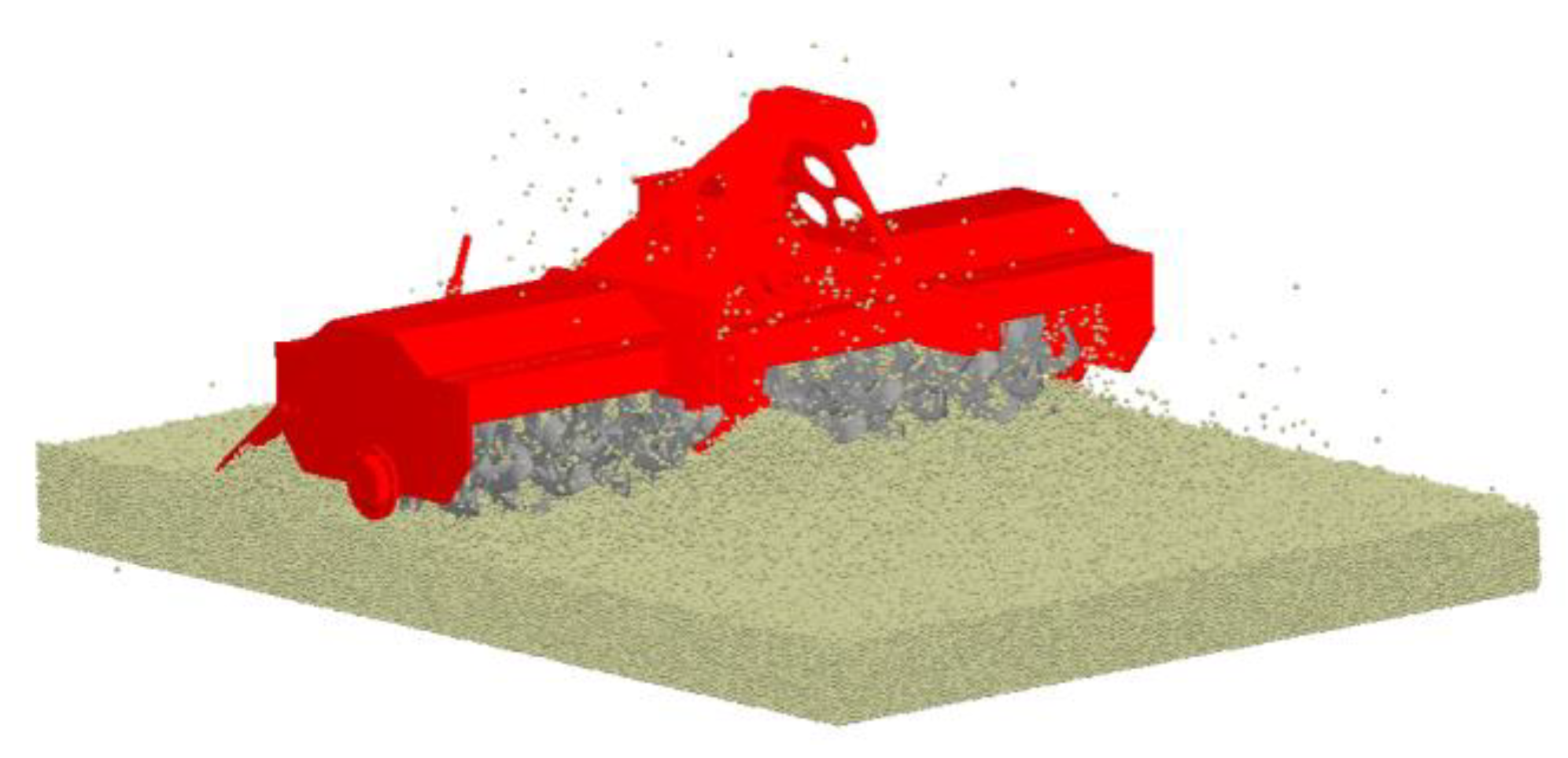
4. Discrete Element Simulation

Using EDEM 2023 software, the discrete element simulation model of the high-speed rotary tiller was established. The regression equations of the key factors of the high-speed rotary tiller obtained from the above analysis, the soil-breaking rate, and land surface flatness after operation were established through an orthogonal test, so as to analyze the effects of the interactions of various factors on the soil-breaking rate and land surface flatness, obtaining an optimal combination of factors, which provides the basis for the subsequent trial production of the rotary tiller.

4.1. Simulation Modeling and Experimental Design

This simulation test mainly simulated the tillage operation of alkaline soil in the experimental field of the National Agricultural High-Tech Industry Demonstration Area of the Yellow River Delta of Dongying City, Shandong Province. The soil particle contact model selected was Hertz–Mindlin with bonding; this model can simulate the bonding of soil particles and the formation of bonds between the particles until it reaches the bonding rupture limit [28,29].
The Hertz–Mindlin with bonding model can withstand the tangential force, Ft, normal force, Fn, normal moment, Tn, and tangential moment, Tt, on the particles until the bond breaks, i.e., the bond is damaged. The bond force is gradually adjusted from the 0 time step; the bond is subjected to the tangential force and normal force until it reaches the critical value of fracture, with the critical tangential and normal stresses, as shown in Equation (18).
σ m a x < F n A + 2 T t J R B τ m a x < F t A + 2 T n J R B
where A is the contact area; J is the moment of inertia; RB is the bond radius; Ft is the tangential force between particles; Fn is the normal force between particles; Tn and Tt are the normal and tangential moments between particles.
The radius of soil particles is set to 5 mm, and the radius of the bonding key is set to 5.1 mm. The material of the rotary tiller knife is 65 Mn steel, and the rotary tillage depth is set to 14 cm according to the working condition. A soil trough with dimensions of (length × width × height) 3000 mm × 2200 mm × 300 mm was built into the model, a particle factory was set up above the soil trough, and the gravitational deposition method was used to generate 5,792,000 soil particles, imported into the simplified rotary tiller model. For simulation parameters, through preliminary research on the mechanical properties and contact parameters of saline soil, the intrinsic parameters and contact parameters of each material required for the simulation model were selected for experimental determination [30,31,32,33,34,35,36,37,38]. The simulation contact model parameters and simulation contact parameters are shown in Table 1 and Table 2.
In order to ensure the continuous movement of soil particles in the machine simulation process, a fixed time step of 3.74 × 10⁻⁵ was set, which is 15% of the Rayleigh time step, with the size of the grid cell being 2.5 times the radius of the smallest particles. The rotary tiller was simulated for the field operation simulation; the simulation process is shown in Figure 8. Figure 9 shows the effects of the rotary tiller soil-cutting operation at different moments in the simulation test. Figure 9a shows the moment of operation of the rotary tiller at 1 s; Figure 9b,c show the moment of soil penetration of the rotary tiller at 2 s and the moment of stabilized operation of the rotary tiller at 3 s.
We used Design-Expert13 experimental design software to carry out the response surface method, central combination experimental design (CCD). Based on the previous analysis, the rotary tillage knife roller speed, n, tillage depth, h, and implement forward speed, vm, were selected as the experimental factors. A ternary quadratic regression orthogonal rotary combination design was carried out; the experimental factor coding and levels are shown in Table 3. In the simulation, the soil-breaking rate and land surface flatness were selected as the test indexes.
According to the requirements for determining the soil-breaking rate, the rotary tiller works to break the internal bonding ring of the soil block, so that the soil block is broken into small soil pieces, where the maximum side length of the soil block is less than 40 mm for qualified soil blocks [26]. In the EDEM particle setup, soil particles are bonded to each other using bonding bonds, and after the simulation is completed, the total number of bonding bonds versus the total number of ring-breaking bonding bonds is calculated to compute the soil-breaking rate.
The post-tillage land surface flatness was determined by using the Clipping module of EDEM software to randomly select a 100-mm-thick slice at the back of the rotary tiller, as shown in Figure 10, the random slice data collection method. The surface particle coordinates of this slice were extracted and imported into CAD 2021 software to connect the surface particle coordinates with a spline curve to draw the surface line after plowing [15]. A horizontal straight line was made over the highest point as the reference line, and the measuring points were marked in 50 mm equal parts within the working width of 800 mm. The vertical distance from the horizontal datum line to the surface line was measured at each point and recorded as ai. We calculate the mean value of the vertical distance, am, and the standard deviation, U, for each point.
a m = i = 1 a a i n U = i = 1 n a i a m 2 n 1
where n is the number of points per measurement.
Each set of tests was measured three times, and the land surface flatness is expressed as the standard deviation mean, Um.

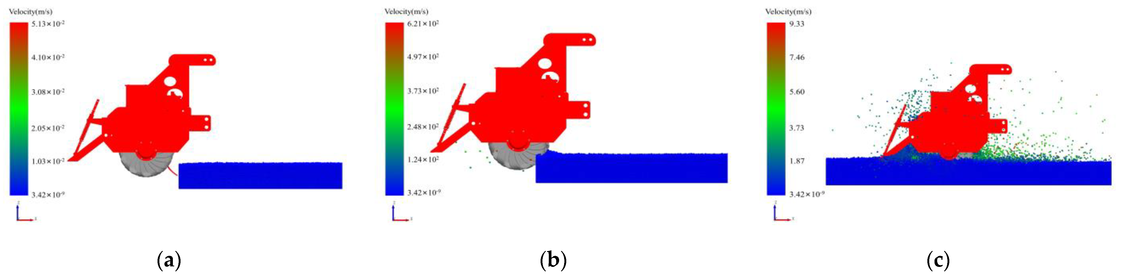
4.2. Simulation Results Analysis

The soil-breaking rate and ground leveling of the rotary tiller were obtained by performing 20 sets of simulation tests on the EDEM. The results of the measurements are shown in Table 4, where A, B, and C are the coded values of the knife roller speed, rotary tillage depth, and machine forward speed test factors. The experimental results were processed using Design-Expert13 software to analyze the significance of the effects of the knife roller speed, n/r·min, tillage depth, h/cm, and unit forward speed, v/km·h on the soil-breaking rate % and land surface flatness mm; the regression equations were fitted to obtain the response model of the measured indexes.
The test results in Table 4 were tested for significance and analyzed by analysis of variance. A quadratic polynomial regression equation was chosen to obtain the significance test results of the regression models of the soil-breaking rate in Table 5 and land surface flatness in Table 6. The regression coefficients in the regression models were subjected to the F-test and analysis of variance to establish the quadratic polynomial regression equations of the soil-breaking rate, Y1, and land surface flatness, Y2, on the speed of cutter rollers, t, the tillage depth, and the forward speed of the implements, respectively:
Y 1 = 85.07 + 5.10 A 0.3455 B 6.04 C + 2.31 A B + 1.36 A C + 1.54 B C 3.65 A 2 + 0.5367 B 2 0.8422 C 2
Y 2 = 24.17 5.76 A 0.4254 B + 8.27 C 3.64 A B 1.66 A C 1.96 B C + 4.42 A 2 + 1.33 B 2 + 2.00 C 2
As can be seen in Table 5, the model significance p-value for the objective function Y1 is <0.0001, which is less than 0.01, indicating that the regression model is highly significant. The p-value of the misfit term is 0.9949, which is greater than 0.05, proving that no misfit factor exists and the model is well-fitted. The items analyzed—A, C, AB, and A2—had a highly significant impact on the soil fragmentation rate. AC and BC were significant terms, and B, B2, and C2 were non-significant terms.
As can be seen from Table 6, the model significance p-value for the objective function Y2 is <0.0001, which is less than 0.01, indicating that the regression model is highly significant. The p-value of the misfit term is 0.6322, which is greater than 0.05, proving that no misfit factor exists and the model is well-fitted. The items analyzed—A, C, AB, BC, A2, C2—had a highly significant effect on surface leveling. The terms B, AC, and B2 were significant terms.
The F value in the table indicates the influence of each influencing factor on the test indexes; the larger the F value, the greater the influence on the test indexes. As can be seen in Table 5 and Table 6, the influence of each test factor on the soil-breaking rate, Y1, and the land surface flatness, Y2, is in the following order from the largest to the smallest, as follows: C—machine forward speed, A—knife roller rotary speed, and B—tillage depth.

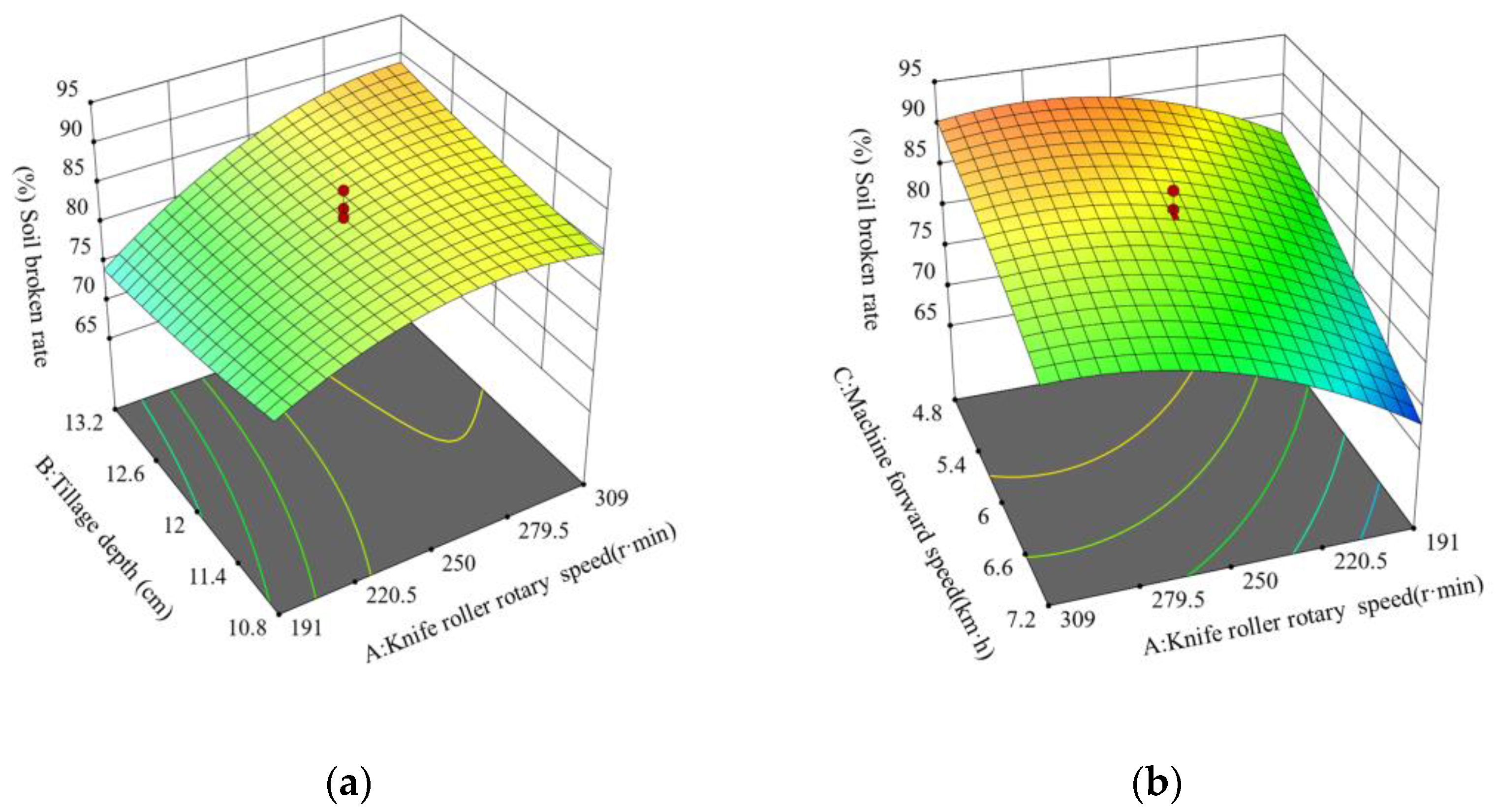
Response Surface Analysis

From the regression significance analysis of the soil fragmentation rate and surface flatness, it can be seen that the knife roller speed and tillage depth, tillage depth and unit forward speed, and unit forward speed and tillage depth have interaction effects on the soil fragmentation rate; the knife roller speed and tillage depth, knife roller speed and unit forward speed, and tillage depth and unit forward speed have interaction effects on surface flatness; the response surfaces of the plotted interactions are shown in Figure 11.
From Figure 11a, it can be seen that at the center level of the forward speed of the unit, when the plowing depth is certain, there is a significant increase in the soil-breaking rate with the increase in the knife roller’s rotational speed; when the knife roller’s rotational speed is certain, with the decrease in the plowing depth, the soil-breaking rate increases as a consequence. As can be seen in Figure 11b, when the plowing depth is at the center level, the soil-breaking rate increases with the decrease in the unit forward speed and the increase in the cutter roll speed. As can be seen in Figure 11c, at the center level of the knife roller speed, there is a significant increase in the soil fragmentation rate as the forward speed of the unit decreases and the depth of tillage decreases. From Figure 11d, it can be seen that at the center level of the forward speed of the unit, when the rotational speed of the knife roller is certain, there is a significant decrease in the surface flatness with the reduction in the plowing depth and the increase in the rotational speed of the knife roller. From Figure 11e, it can be seen that there is a significant decrease in the surface flatness when the rotational speed of the knife rollers is increased, and the forward speed of the unit is decreased when the tillage depth is at the center level. From Figure 11f, when the rotational speed of the knife roller is at the center level, it can be seen that when the forward speed of the unit and the plowing depth are reduced, the surface flatness tends to decrease and then increase.

4.3. Optimal Parameter Combinations for High-Speed Rotary Tillers

By means of the quadratic orthogonal rotary combination test, it is necessary to determine the optimal combination of parameters affecting the rate of soil-breaking and land surface flatness, thus improving the quality of rotary plowing and land preparation. We determine the objective function and constraint function equation as follows:
m a x Y 1 A , B , C m i n Y 2 A , B , C s . t . 150 r / m i n A 350 r / m i n 10 c m B 14 c m 4 k m / h C 8 k m / h
where maxY1(A,B,C) is the objective function and minY2(A,B,C) is the constraint function.
According to the objective function and constraint function model, the regression equation, Equation (21), was optimized using Design-Expert13 software to obtain the optimal parameter combinations of the factors affecting the soil-breaking rate and surface flatness. When the rotational speed A of the knife roller is 309 r/min, the plowing depth is 13.2 cm, the forward speed of the unit is 4.8 km/h, the soil fragmentation rate is 91.3%, and the land surface flatness is 17.4 mm. Considering that a knife roller speed of 309 r/min is not easy to set (regarding gearbox transmission), the knife roller speed was determined to be 310 r/min. In order to verify the accuracy of the optimization results, the optimal combination of parameters was used to re-carry out the simulation. The average values from three times were determined, resulting in an optimal crushing rate of 90.6% and a surface flatness of 18.2 mm. The simulation test results were basically the same as the theoretical results, indicating that the regression equation is accurate.

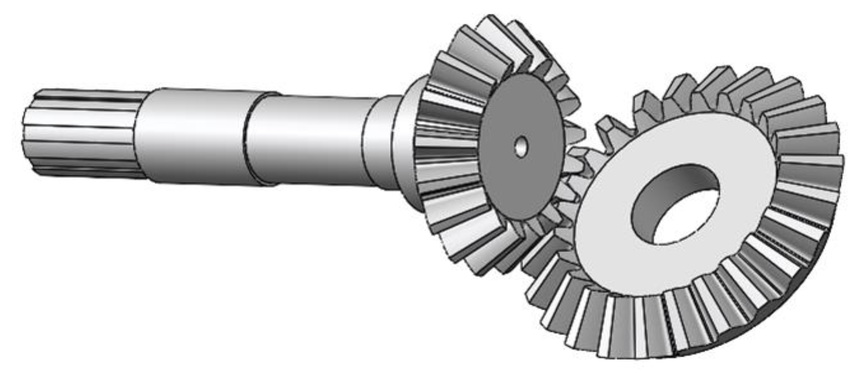
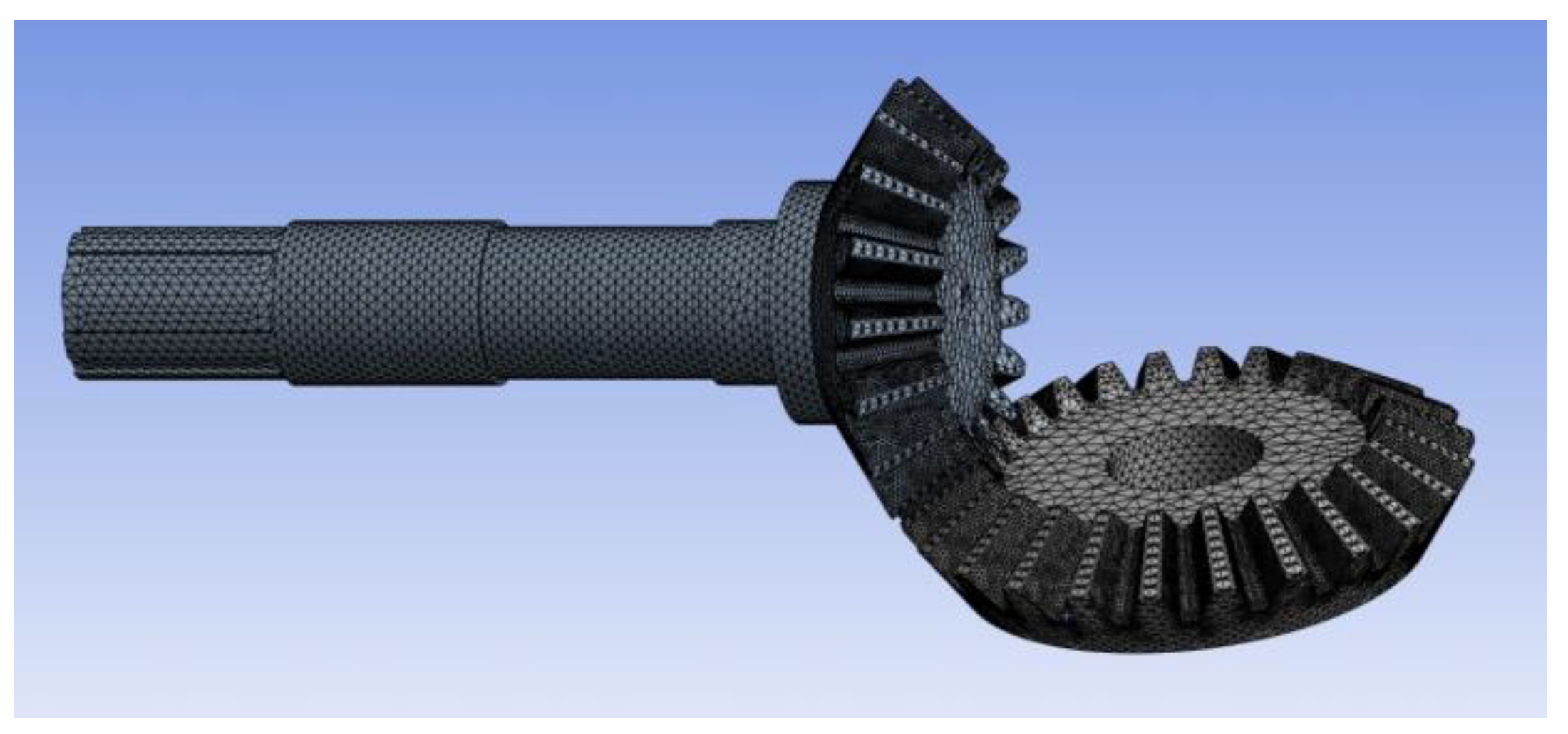
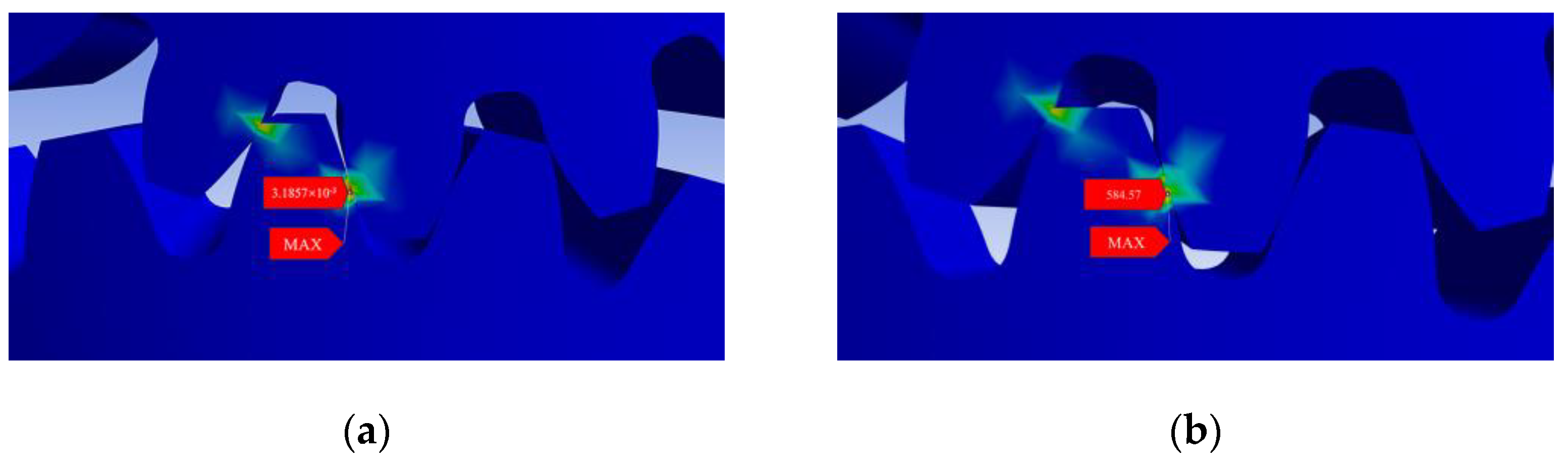
4.4. Transient Analysis of Gearbox Meshing Bevel Gears

We determined the knife roller speed to be 310 r/min and rematched the gears in the gearbox in order to change the transmission ratio and achieve a consistent knife roller speed. According to the rotary tillage operation process, the transmission parts of the force situation show that straight-toothed bevel gears and the main shaft meshing with bevel gears are the most likely to fail. The main vibration load source is the bevel gear. Due to its transmission ratio changes, the bevel gear undergoes significant changes. Therefore, the dynamic loads are mainly affected by the bevel gears, while the influences of other gears in this analysis are negligible. Therefore, a transient structural simulation of bevel gears during meshing was carried out.
We separately established each part of the parts model and then assembled them. The bevel gear and spindle, after assembly, are shown in Figure 12. The bevel gear and spindle materials used in this test were 20CrMnTi, with a material density of 7800 kg/m3, a modulus of elasticity of 2.07 × 10¹¹ Pa, and a Poisson’s ratio of 0.25. The material properties of the bevel gear and the spindle are defined in the ANSYS Workbench materials engineering database [39].
The meshing accuracy determines the accuracy of the finite element analysis results, and due to the complex structure of the bevel gear, a tetrahedral mesh was used for the division in this test [40]. Bevel gear meshing mainly relies on the tooth surface to transfer motion and force; therefore, the meshing tooth profile needs mesh refinement; in order to more accurately derive the stress distribution between the tooth profile, the mesh cell division size of the tooth profile is set to 1.5 mm. By controlling the division of the overall and local meshes, the final number of mesh nodes is 322,068 and the number of mesh cells is 186,889. The three-dimensional model of the bevel gear assembly after meshing is shown in Figure 13.
Finite Element Result Analysis
The transient dynamics simulation of the bevel gear pair is analyzed and solved. The maximum equivalent force cloud (Figure 14a) and maximum equivalent strain cloud (Figure 14b) at 310 r/min were obtained, as shown in Figure 14.
From the mechanics of the materials, it is known that in order for the structure to have sufficient strength, the actual working stress of the structure under load should be lower than its ultimate stress. In the strength calculation, a factor greater than 1 is used to divide the ultimate stress, and the result is called the permissible stress [σ].
σ = σ s / S
where S is the safety factor and σs is the material yield strength.
From the maximum equivalent stress cloud and maximum equivalent strain cloud, it can be seen that their maximum values both appeared at the large end of the meshing of the bevel gear. At a rotational speed of 310 r·min, the maximum equivalent force value was 584.57 MPa and the maximum equivalent strain value was 3.1587 × 10⁻³ mm. As the material of the bevel gear is 20CrMnTi, its yield strength is 835 MPa, the safety factor is 1.2, and its allowable stress is 695.8 MPa. From the maximum equivalent force cloud diagram of the bevel gear, it can be seen that the maximum equivalent force value of the bevel gear pair is 584.57 MPa, which is less than the allowable stress of the material and meets the strength requirements [41].

5. Field Trials

5.1. Experimental Condition

The field test was conducted on a high-speed rotary tiller on 26 October 2024, in the Yellow Triangle Agricultural High-altitude Zone, Dongying City, Shandong Province, and the field test site is shown in Figure 13. The test equipment mainly consisted of a DEUTZ-FAHR CD1804 tractor, a high-speed rotary tiller prototype, an ordinary rotary tiller (1GKN-200), a ring cutter, a tape measurer (1–5 m), a steel plate ruler (1–300 mm), an electronic scale, a sealed bag, a leather tape measurer (1–50 m), a 0.5 m × 0.5 m square box, a soil firmness tester (ZHENJIANG TOP CLOUD-AGRI TECHNOLOGY CO., Zhenjiang, China; TJSD-750-II), and a soil moisture tachymeter (ZHENJIANG TOP CLOUD-AGRI TECHNOLOGY CO., TZS-1K-G).
Soil firmness is a reflection of the ability of soil to resist external compaction and fragmentation, which directly affects the resistance to tillage. In this paper, the soil firmness of the experimental field at a depth of 0–300 mm was measured by the five-point method using the TOP CLOUD soil firmness sensor, as shown in Figure 15a. The measured values of surface firmness are shown in Table 7. At the same time, the average soil moisture content was 23.6%, determined by using a TOP CLOUD Environmental Monitor with a soil moisture sensor, as shown in Figure 15b. The measured data are shown in Table 7. Soil samples were taken from a 0 to 300 mm soil layer using a five-point sampling method via a ring knife; the measured soil bulk density was 2.13 g·cm−3. The soil pH value was measured using a TOP CLOUD soil pH sensor, and the average of the measurements was taken in three trials. The measured soil pH value is shown in Table 7. The rest of the experimental plots were characterized, as shown in Table 7.

5.2. Test Methods

For the field test, the test field was divided into three plots that were 50 m long and 1.5 times wider than the machine, with the first 10 m of each plot being the machine acceleration zone and the middle 20 m being the machine forward stabilization zone. According to the optimized high-speed rotary tiller, at a cutting pitch of 6.9 cm, the forward speed of the implement was 5.2 km·h, and the rear output shaft of the tractor was 760 r·min, so the rotational speed of the cutter shaft was stabilized at 310 r·min, and the plowing depth was controlled at 14 cm; the test was repeated three times. For the machine test method—according to the NY/T499-2013 [42], Operating Quality for Rotary Tillers (Ministry of Agriculture of the People’s Republic of China: Beijing, China, 2013) and the GB T5668-2017, Quality Standard for Rotary Tiller Operation (Standardization Administration of China: Beijing, China, 2017), the depth of tillage, tillage stability, soil fragmentation rate, vegetation cover, and surface leveling were used as test indicators.

5.2.1. Tillage Depth and Tillage Depth Stability

In the measurement area after the machine tool operation, along the forward direction of the machine tool, points were selected every 2 m along both the right and left sides, each trip involving a measurement of 20 points. A steel plate ruler was inserted into the soil to measure the depth of rotary plowing at each measurement point, across a total of three trips [40]. The plowing depth was calculated according to Equations (23) and (24); the stability of the plowing depth under working conditions was calculated according to Equations (25) and (26). When calculating, the left and right measuring points of a stroke are each counted as separate strokes.
a j = i = 1 n j a j i n j
j = 1 N a j N
where aj is the average value of plowing depth for the jth stroke, cm; aji is the plowing depth value of the ith measuring point in the jth trip, cm; nj is the number of measurement points in the jth stroke; a is the average value of working plowing depth, cm; N is the number of strokes in the same operating condition.
S j = i = 1 n j a j i a n j 1
S = j = 1 N S j 2 N
Z = S a × 100
U = 1 Z
where Sj is the standard deviation of the plowing depth of the jth trip, cm; S is the standard deviation of working plowing depth, cm; Z is the coefficient of variation of working condition tillage depth, %; U is the working condition tillage depth stabilization factor, %.

5.2.2. Soil-Breaking Rate

The soil-breaking rate was determined using a five-point sampling method, where the full tillage soil within a 0.5 m × 0.5 m area was measured in the measurement area after the machine operation, and the percentage of the mass of soil blocks smaller than 4 cm to the total mass of soil blocks was taken as the broken rate; one point was measured in each stroke, and the test was repeated three times to obtain the mean value [41].
G r = G b G t × 100 %
where Gb is the mass of soil blocks smaller than 4 cm in the full tillage layer, kg; Gt is the total mass of soil blocks in the full tillage layer, kg.

5.2.3. Vegetation Coverage Rate

Five points were selected in the measurement area to measure the mass of straw on the ground surface before and after the operation in an area of 1 m × 1 m, and the average value of the five points was calculated to obtain the vegetation cover rate according to Formula [43,44].
F b = W q W h W q × 100 %
where Fb is the vegetation coverage rate, %; Wh is the average value of vegetation mass on the surface after plowing, g; Wq is the average value of vegetation mass on the surface before plowing, g.

5.2.4. Test Method for Land Surface Flatness

Along the direction perpendicular to the forward direction of the machine, above the highest point of the ground surface, a horizontal datum line was selected, the same width as the machine, and divided into 10 equal points. This was to determine the vertical distance from each equal point to the ground surface, calculate the standard deviation according to Formula (26), measure three groups of data for each stroke, and express the levelness of the surface of the ground after plowing as the average of the standard deviation [45].

5.3. Test Results and Analysis

According to the optimization results, after the second orthogonal rotary combination test, the optimal parameter combination values were selected for the rotary tiller, as follows: a knife roller rotational speed of 310 r/min, tillage depth of 13.2 cm, and a forward speed of 4.8 km/h; a validation test was carried out. In addition to the soil fracture rate and surface leveling, three tillage indexes, namely, tillage depth, tillage depth stability coefficient, and straw cover, were examined in order to test the overall effects of the analyzed optimal parameter combinations on the stability of machine tillage. The field test is shown in Figure 16. A total of five replicated tests were conducted, and the average values were taken after the tests. The results of the prototype and the ordinary rotary tiller after the field tests are shown in Table 8.
A comparison of the field test results and simulation test results of the high-speed rotary tiller shows that the simulation soil fragmentation rate is approximately the same as the field test results, with a difference of 1.3%; the simulation surface flatness is slightly larger than the field test results, with a difference of 2.2 mm. Considering that the floating action of the rototiller drag plate could not be realized during the simulation, resulting in a surface-leveling error, the simulation basically reflects the surface effect after the implements are operated.
The results of the field test show that the soil-crushing rate, plowing depth, and surface leveling after the high-speed rotary tiller operation are 89.3%, 14.2 mm, and 16.4 mm, and the stability of the plowing depth and the vegetation coverage rate has reached more than 90%, i.e., the machine can complete the soil crushing, surface leveling and stubble returning to the field in multiple operation processes at one time, meeting the requirements of the local agronomy.
The results of the test against the ordinary rotary tiller showed that, at the level of operation quality, the high-speed rotary tiller operation was better than the ordinary rotary tiller in terms of the soil-breaking rate, surface flatness, plowing depth, plowing depth stability coefficient, and straw coverage rate. Regarding economic benefits, the operating speed of the high-speed rotary tiller in the field test was 4.8 km/h, while the operating speed of the ordinary rotary tiller was 3.5 km/h. The operating speed of the high-speed rotary tiller compared with the ordinary rotary tiller increased by 1.3 km/h and above; the operating efficiency per unit of the operating area increased by 37.1%; and the operation quality and operating efficiency were much better than those of the ordinary rotary tiller. The replacement of more wear-resistant rotary plow knives can improve the blade life by more than 30% and reduce daily maintenance costs [46,47].
As can be seen from the operation effect comparison chart in Figure 17, a high-speed rotary tiller can meet the agronomic requirements in one operation, so that the soil reaches the state to be sown; the ordinary rotary tiller needs two operations to achieve the above effect.

6. Conclusions

Aiming at the problems of solid and sclerotic soil in the saline lands of Binhai New Area, along with the poor quality and low efficiency of traditional rotary tillage operations, we designed a high-speed rotary tiller that can meet the operating requirements of saline land through theoretical analysis, orthogonal experiments, discrete element simulation, and other methods. The findings are summarized as follows:
(1)
Aiming at the problem of efficiency of land preparation in saline land in Binhai New Area, a high-speed rotary tiller is designed to increase the number of successive cuts of rotary tiller knives per unit of time by determining the number of rotary tiller knives in the same plane and rotational speed of the knife axle, to reduce the time of soil cutting, improve the quality of rotary tillage and operational efficiency, and meet the requirements of local agronomic techniques in a single operation.
(2)
The theoretical analysis focused on the rotary tillage knife trajectory, the number of blades, and the arrangement of the helix rising angle, to determine the main factors affecting the quality of operation for the knife roller speed, plowing depth, and unit forward speed. Combined with the central orthogonal test and discrete element simulation, the optimal parameter combination for the high-speed rotary tiller is determined as follows: a knife roller speed at 310 r/min, tillage depth of 13.2 cm, and forward speed of the unit at 4.8 km/h. At this time, the simulation values of the soil-breaking rate and the land surface flatness were 90.6% and 18.2 mm, respectively.
(3)
Under the optimal combination established through field comparison tests, the results for the high-speed rotary tiller compared to the ordinary rotary tiller operation for the soil-breaking rate, tillage depth, tillage depth stability coefficient, and vegetation cover were 89.3%, 14.2 cm, 92.8%, 90.3%. The land surface flatness was 16.4 mm, which is superior to the ordinary rotary tiller operation effect, meeting the peanut pre-sowing preparation agronomic requirements for saline land in Binhai New Area.
(4)
The high-speed rotary tiller designed in this study performed remarkably in field trial operations in coastal saline soils, meeting the local agronomic requirements. However, its performance in other soil types (e.g., clay, sand, etc.) and under different humidity conditions needs to be verified. Differences in the physicochemical properties of soils may affect operating results, and soils that are too wet or too dry may require modifications to the machine construction to accommodate varying moisture working conditions. High-speed rotary tiller blades are prone to faster wear at high rotational speeds, requiring the use of wear-resistant materials or coatings to extend blade life. In the future, field tests will be conducted under different soil types and humidity conditions to optimize blade materials, and fatigue life tests will be conducted on key components to improve their reliability under long-term high loads. In addition, the matching of high-efficiency power systems with tractors will be studied to optimize energy consumption, reduce tractor power requirements, and improve overall operating efficiency.

Author Contributions

Conceptualization, S.Z. and Z.Z.; methodology, S.Z.; software, T.L. (Tong Lu) and J.L.; validation, S.Z. and Z.Z.; formal analysis, S.Z.; investigation, M.H. and M.T.; data curation, Z.Z., S.Z. and T.L. (Tao Liu); writing—original draft preparation, S.Z.; writing—review and editing, D.W., Z.Z. and Y.T.; visualization, S.Z. and S.G.; supervision, Z.Z. and Y.T.; project administration, Y.T. and S.G.; funding acquisition, Y.T., S.G. and D.W. All authors have read and agreed to the published version of the manuscript.

Funding

This research obtained funding from the National Key Research and Development Plan (Project number: 2022YFD2300089); the Shandong Key Research and Development Plan (project number: 2021CXGC010813); the Shandong Key Research and Development Plan (Science and Technology Demonstration Project) (project number: 2024SFGC0405); and the Saline Land Tillage Mechanization Equipment Research and Development, Manufacturing, and Popularization of Application (project number: NJYTHSD-202314). The project was also supported by the Science & Technology Specific Projects in Agricultural High-tech Industrial Demonstration Area of the Yellow River Delta (project number: 2022SZX07).

Institutional Review Board Statement

Not applicable.

Data Availability Statement

The data presented in this paper are available upon request from the authors.

Conflicts of Interest

The authors declare no conflicts of interest.

References

  1. Qin, K.; Ding, W.M.; Fang, Z.C.; Du, T.T.; Zhao, S.Q.; Wang, Z. Design and experiment of plowing and rotary tillage combined machine. Trans. Chin. Soc. Agric. Eng. 2016, 32, 7–16. [Google Scholar]
  2. Zhu, Q.Z.; Wu, G.W.; Chen, L.P.; Meng, Z.J.; Shi, J.T.; Zhao, C.J. Design of Stratified and Depth-Fixed Application Device of Base-fertilizer for Winter Wheat Based on Soil-covering Rotary Tillage. Trans. Chin. Soc. Agric. Eng. 2018, 34, 18–26. [Google Scholar]
  3. Gao, J.M.; Zhou, P.; Zhang, B.; Li, F.Y. Development and Test of High Speed Soil-cutting Simulation System Based on Smooth Particle Hydrodynamics. Trans. Chin. Soc. Agric. Eng. 2007, 8, 20–26. [Google Scholar]
  4. Liu, G.Y.; Xia, J.F.; Zheng, K.; Cheng, J.; Wei, Y.S.; Guo, L.W.; Li, X.F.; Zhang, J.M. Design and Experiments of the Barrier Type Rotary Anti-adhesion Blade Roller with Vibration Crosspiece. Trans. Chin. Soc. Agric. Eng. 2022, 38, 29–40. [Google Scholar]
  5. Fang, H.M.; Ji, C.Y.; Zhang, Q.Y.; Guo, J. Force Analysis of Rotary Blade Based on Distinct Element Method. Soc. Agric. Eng. 2016, 32, 54–59. [Google Scholar]
  6. Zhao, Z.; Wang, D.W.; Shang, S.Q.; Guo, P.; Gao, Z.H.; Xia, C.; Yan, H.P.; Hou, J.L. Design and Test of a Dual-axis Layered Rotary Tillage Stubble Exterminator in Saline-alkali Land based on Discrete Elements. Int. J. Agric. Biol. Eng. 2024, 17, 163–175. [Google Scholar] [CrossRef]
  7. Li, W.; Yang, J.; Tang, C.; Liu, X.; Xie, W.; Yao, R.; Wang, X. The Temporal–Spatial Dynamic Distributions of Soil Water and Salt under Deep Vertical Rotary Tillage on Coastal Saline Soil. Water 2022, 14, 3370. [Google Scholar] [CrossRef]
  8. Upadhyay, G.; Raheman, H. Effect of Velocity Ratio on Performance Characteristics of an Active-passive Combination Tillage Implement. Biosyst. Eng. 2020, 191, 1–12. [Google Scholar] [CrossRef]
  9. Salokhe, V.M.; Ramalingam, N. Effects of Direction of Rotation of a Rotary Tiller on Properties of Bangkok Clay Soil. Soil Tillage Res. 2001, 63, 65–74. [Google Scholar] [CrossRef]
  10. Asl, J.H.; Singh, S. Optimization and Evaluation of Rotary Tiller Blades: Computer Solution of Mathematical Relations. Soil Tillage Res. 2009, 106, 1–7. [Google Scholar] [CrossRef]
  11. Tian, Y.; Jin, L.; Zhao, Y.X. Experimental Research on the Paraments Impacted Homework PerFormance of Rotary Cultivator. J. Chin. Agric. Mech. 2016, 37, 1–4. [Google Scholar]
  12. Zheng, K.; McHugh, A.D.; Li, H.W.; Wang, Q.J.; Liu, C.Y.; Hu, H.N.; Liu, W.Z.; Zhang, Z.Q.; Liu, P.; He, J. Design and Experiment of Anti-vibrating and Anti-wrapping Rotary Components for Subsoiler Cum Rotary Tiller. Int. J. Agric. Biol. Eng. 2019, 12, 47–55. [Google Scholar] [CrossRef]
  13. Yang, Q.L.; Chen, G.B.; Xie, L.J.; Wang, Q.J.; He, J.; Li, H.W. Design and Experiment of Telescopic Finger Stalk of Maize Straw Burying Machine. Trans. Chin. Soc. Agric. Mach. 2020, 51, 35–45. [Google Scholar]
  14. Zhang, C.L.; Xia, J.F.; Zheng, J.M.; Zhou, H.; Zhu, Y.H.; Wang, J.W. Design and Experiment of Knife Roller for Six-head Spiral Straw Returning Cultivator. Trans. Chin. Soc. Agric. Mach. 2019, 50, 25–34. [Google Scholar]
  15. Zheng, K.; Li, Y.F.; Xia, J.F.; Liu, G.Y.; Cheng, J.; Kang, Q.X. Design and Experiment of Land Leveling Blade Roller of Ditching and Rotary Tiller with Gradual Spiral Angle. Trans. Chin. Soc. Agric. Mach. 2021, 52, 63–73. [Google Scholar]
  16. Matin, M.A.; Desbiolles, J.M.A.; Fielke, J.M. Strip-tillage using Rotating Straight Blades: Effect of Cutting Edge Geometry on Furrow Parameters. Soil Tillage Res. 2016, 155, 271–279. [Google Scholar] [CrossRef]
  17. Shi, J.Y.; He, R.Y.; Tao, S.K.; Xu, G.M.; Fan, C.; Ding, Q.S. Design and Operation Parameter Optimization of Plowing-Rotary-Leveling Compound Tiller; Nanjing Agricultural University: Nanjing, China, 2024. [Google Scholar]
  18. Qin, K.; Ding, W.M.; Fang, Z.C.; Du, T.T.; Zhao, S.Q.; Wang, Z. Analysis and Experiment of Tillage Depth and Width Stability for Plowing and Rotary Tillage Combined Machine. Trans. Chin. Soc. Agric. Eng. 2016, 32, 1–8. [Google Scholar]
  19. Li, B.F. Agricultural Mechanics; China Agricultural Press: Beijing, China, 2017. [Google Scholar]
  20. Yang, Y.W.; Tong, J.; Ma, Y.H.; Jiang, X.H.; Li, J.G. Design and Experiment of Biomimetic Rotary Tillage Blade Based on Multiple Claws Characteristics of Mole Rats. Trans. Chin. Soc. Agric. Eng. 2019, 35, 37–45. [Google Scholar]
  21. Yang, Y.; Hu, Z.; Gu, F.; Ding, Q. Simulation and Experimental Study of the Tillage Mechanism for the Optimal Design of Wheat Rotary Strip–Tiller Blades. Agriculture 2023, 13, 632. [Google Scholar] [CrossRef]
  22. Zhang, X.; Zhang, L.; Hu, X.; Wang, H.; Shi, X.; Ma, X. Simulation of Soil Cutting and Power Consumption Optimization of a Typical Rotary Tillage Soil Blade. Appl. Sci. 2022, 12, 8177. [Google Scholar] [CrossRef]
  23. GB T5669-2017; Rotary Tiller—Rotary Blades and Blade Holders. National Technical Committee for Standardization of Agricultural Machinery: Beijing, China, 2017.
  24. GB T5668-2017; Rotary Tiller. Standardization Administration of China: Beijing, China, 2017.
  25. Zhai, S.; Shi, Y.; Zhou, J.; Liu, J.; Huang, D.; Zou, A.; Jiang, P. Simulation Optimization and Experimental Study of the Working Performance of a Vertical Rotary Tiller Based on the Discrete Element Method. Actuators 2022, 11, 342. [Google Scholar] [CrossRef]
  26. Zhao, J.G.; Wang, A.; Ma, Y.J.; Li, J.C.; Hao, J.J.; Nie, Q.L.; Long, S.F.; Yang, Q.F. Design and Test of Soil Preparation Machine Combined Subsoiling, Rotary Tillage and Soil Breaking. Trans. Chin. Soc. Agric. Eng. 2019, 35, 46–54. [Google Scholar]
  27. Xiao, M.H.; Niu, Y.; Wang, K.X.; Zhou, J.B.; Ma, R.Q. Design of Self-excited Vibrating Rotary Tiller and Analysis of Its Performance in Reducing Torsion and Consumption. Trans. Chin. Soc. Agric. Mach. 2022, 53, 52–63. [Google Scholar]
  28. Guo, L.; Fang, Q.M.; Li, M.F.; Wang, Z.; Wang, C.; Zhang, L.Y. Parameter Calibration for Discrete Element Simulation of Red Clay Soils in Sloping Cropland in Central Yunnan. Trans. Chin. Soc. Agric. Mach. 2024, 55, 185–193+285. [Google Scholar]
  29. Adajar, J.B.; Alfaro, M.; Chen, Y.; Zeng, Z.W. Calibration of discrete element parameters of crop residues and their interfaces with soil. Comput. Electron. Agric. 2021, 188, 106349. [Google Scholar] [CrossRef]
  30. Mak, J.; Chen, Y.; Sadek, M.A. Determining Parameters of a Discrete Element Model for Soil–tool Interaction. Soil Tillage Res. 2012, 118, 117–122. [Google Scholar] [CrossRef]
  31. Wu, Z.Y.; Wang, X.S.; Liu, D.W.; Xie, F.P.; Ashwehmbom, L.G.; Zhang, Z.Z.; Tang, Q.J. Calibration of Discrete Element Parameters and Experimental Verification for Modelling Subsurface Soils. Biosyst. Eng. 2021, 212, 215–227. [Google Scholar] [CrossRef]
  32. Sun, J.B.; Liu, Q.; Yang, F.Z.; Liu, Z.J.; Wang, Z. Calibration of Discrete Element Simulation Parameters of Sloping Soil on Loess Plateau and Its Interaction with Rotary Tillage Components. Trans. Chin. Soc. Agric. Mach. 2022, 53, 63–73. [Google Scholar]
  33. Wang, D.W.; Lu, T.; Zhao, Z.; Shang, S.Q.; Zheng, S.; Liu, J. Calibration of Discrete Element Simulation Parameters for Cultivated Soil Layer in Coastal Saline alkali Soil. Trans. Chin. Soc. Agric. Mach. 2024, 55, 240–249. [Google Scholar]
  34. Liu, M.; Wang, J.; Feng, W.; Jing, H.; Wang, Y.; Guo, Y.; Xu, T. Calibration of Model Parameters for Soda Saline Soil-Subsoiling Component Interaction Based on DEM. Appl. Sci. 2023, 13, 11596. [Google Scholar] [CrossRef]
  35. Li, M.L.; Wang, L.Z.; Liao, Q.X.; Liao, Y.T.; Xiao, W.L.; Zhang, Q.S. Calibration of Rototilled Soil Discrete Element Parameters after Rotary Tillage in the Preparation Process of Rapeseed Mechanized Direct Seeding Micro-ridge Seed Bed. Trans. Chin. Soc. Agric. Eng. 2023, 39, 10–19. [Google Scholar]
  36. Xiang, W.; Wu, M.L.; Lü, J.N.; Quan, W.; Ma, L.; Liu, J.J. Calibration of Simulation Physical Parameters of Clay Loam Based on Soil Accumulation Test. Trans. Chin. Soc. Agric. Eng. 2019, 35, 116–123. [Google Scholar]
  37. Li, J.W.; Tong, J.; Hu, B.; Wang, H.B.; Mao, C.Y.; Ma, Y.H. Calibration of Parameters of Interaction between Clayey Black Soil with Different Moisture Content and Soil-engaging Component in Northeast China. Trans. Chin. Soc. Agric. Eng. 2019, 35, 130–140. [Google Scholar]
  38. Siddique, M.A.A.; Baek, S.-Y.; Baek, S.-M.; Jeon, H.-H.; Lee, J.-H.; Son, M.-A.; Yoon, S.-Y.; Kim, Y.-J.; Lim, R.-G. The Selection of an Energy-Saving Engine Mode Based on the Power Delivery and Fuel Consumption of a 95 kW Tractor during Rotary Tillage. Agriculture 2023, 13, 1376. [Google Scholar] [CrossRef]
  39. Tian, Y.; Jin, L.; Liu, X.W.; Zhao, Y.X. Model Analysis of the Assembly of Spindle and Straight Tooth Bevel Gear Based on Ansys Workbench. J. Chin. Agric. Mech. 2015, 36, 6–8. [Google Scholar]
  40. Sun, Y.T.; Tian, G.F.; Fu, Y.B. Research on Contact Performance of Spiral Bevel Gear Based on Finite Element Method. J. Mach. Des. 2023, 40, 62–67. [Google Scholar]
  41. Wang, J.Z. Transient Dynamics Analysis of Straight Bevel Gear Mechanisms. J. South. Agric. Mach. 2023, 54, 133–135+156. [Google Scholar]
  42. NY/T499-2013; Operating Quality for Rotary Tillers. Ministry of Agriculture of the People’s Republic of China: Beijing, China, 2013.
  43. Guan, C.S.; Cui, Z.C.; Gao, Q.S.; Wang, S.L.; Chen, Y.S.; Yang, Y.T. Design of Biaxial Rotary Tillage Soil Test Bench and Layered Tillage Test. Trans. Chin. Soc. Agric. Eng. 2021, 3, 28–37. [Google Scholar]
  44. Wang, J.F.; Yang, D.Z.; Fu, Z.D.; Wang, J.W.; Weng, W.X. Design and Experiment of Rice Straw Biaxial Deep-buried Returning Machine. Trans. Chin. Soc. Agric. Mach. 2023, 54, 21–30. [Google Scholar]
  45. Chinese Academy of Agricultural Mechanization Sciences. Agricultural Machinery Design Manual (Part 1); China Agricul-tural Machinery Press: Beijing, China, 2007. [Google Scholar]
  46. Zheng, H.H.; Du, N.; Wei, C.B.; Zhang, C.; Xu, Y. Mechanical Tillage Efficiency of Land Consolidation Based on Plot Area and Shape Trans. Chin. Soc. Agric. Mach. 2024, 55, 232–240+259. [Google Scholar]
  47. Hao, J.J.; Zhan, Z.G.; Hou, J.Y.; Zhao, J.G.; Liu, J.C.; Yin, C.F. Preparation and Microstructure Properties of Fe/WC/CeO2 Plasma Surfacing Layer for Rotary Blades. Chin. Soc. Agric. Eng. 2021, 37, 1–8. [Google Scholar]
Figure 1. Structure of the high-speed rotary tiller. (1) Frame; (2) right knife roller; (3) same cut soil plane; (4) left knife roller; (5) suspension frame; (6) drag plate; (7) gearbox; (a) principal viewpoint; (b) side view.
Agriculture 15 00269 g001
Figure 2. Working process diagram of the high-speed rotary tiller. (1) Soil block; (2) drag plate; (3) blade; and (4) frame.
Agriculture 15 00269 g002
Figure 3. Schematic diagram of the transmission drive. (1) Power input shaft; (2) small bevel gear; (3) large bevel gear; (4–6) drive spur gear; (7) blade; and (8) knife shaft.
Agriculture 15 00269 g003
Figure 4. Coordinate system of the rotary cutter.
Agriculture 15 00269 g004
Figure 5. Rotary cutter soil-cutting operation.
Agriculture 15 00269 g005
Figure 6. Arrangement of rotary knives.
Agriculture 15 00269 g006
Figure 7. Installation arrangement of the rotary cutter.
Agriculture 15 00269 g007
Figure 8. Simulation of the rotary tiller.
Agriculture 15 00269 g008
Figure 9. The effects of different moments in the work of a rotary tiller. (a) 1 s; (b) 2 s; (c) 3 s.
Agriculture 15 00269 g009
Figure 10. Schematic diagram of the data acquisition method for randomly selected slices. (a) Slice position; (b) measurement method.
Agriculture 15 00269 g010
Figure 11. Response surfaces for the effects of factor interactions on the soil-breaking rate and land surface flatness. (a) Response surface plot of the interaction of factors A and B on soil broken rate. (b) Response surface of the interaction of factors A and C on soil broken rate. (c) Response surface of the interaction of factors B and C on soil broken rate. (d) Response surface plot of the interaction of factors A,B on land surface flatness. (e) Response surface plot of the interaction of factors A,C on land surface flatness. (f) Response surface plot of the interaction of factors B,C on land surface flatness.
Agriculture 15 00269 g011aAgriculture 15 00269 g011b
Figure 12. Geometrical model of the assembly of the bevel gear and the main shaft.
Agriculture 15 00269 g012
Figure 13. Meshing of the assembly.
Agriculture 15 00269 g013
Figure 14. Transient simulation cloud map. (a) Maximum equivalent force maps; (b) maximum equivalent variation cloud map.
Agriculture 15 00269 g014
Figure 15. Measurement chart of physical properties of soil. (a) Soil firmness measurement chart; (b) soil moisture content measurement chart.
Agriculture 15 00269 g015
Figure 16. High-speed rotary tiller fieldwork.
Agriculture 15 00269 g016
Figure 17. Comparison of operating effects. (A) High-speed rotary tiller operation effect. Forward speed 4.8 km/h, knife roller speed 310 r/min. (B) Ordinary rotary tiller operation effect. Forward speed 3.5 km/h, knife roller speed 240 r/min.
Agriculture 15 00269 g017
Table 1. Simulation model parameters.
MaterialSoil65 Mn
Density/(kg·m−3)2.27 × 1037.865 × 103
Poisson’s ratio0.320.30
Shear modulus/Pa1.25 × 1067.90 × 109
Table 2. Simulation contact parameters.
ParametricNumerical Value
Soil–soil recovery factor0.35
Soil–soil static friction factor0.5
Soil–soil rolling-friction factor0.15
Soil–steel recovery factor0.3
Soil–steel static friction factor0.5
Soil–steel rolling friction factor0.15
Normal rigidity/N·m−35 × 108
Tangential rigidity/N·m−35 × 108
Critical normal stress/Pa3 × 106
Critical tangential stress/Pa3 × 106
Table 3. Coding of test factors.
EncodingKnife Roller Speed/r·minTillage Depth/cmMachine Forward Speed/km·h
−1.68150104
−119110.84.8
0250126
130913.27.2
1.68350148
Table 4. Experimental program and results.
Serial NumberFactorSoil-Breaking Rate Y1/%Land Surface Flatness Y2/mm
A/r·minB/cmC/km·h
1−1−1−187.322.4
21−1−190.121.8
3−11−178.732.4
411−191.219.1
5−1−1169.444.6
61−1178.139.2
7−11167.448.6
811184.926.8
9−1.680066.747.9
101.680083.425.6
110−1.68087.529.4
1201.68086.326.6
1300−1.6893.415.2
14001.6872.644.6
1500083.424.8
1600086.226.5
1700084.625.1
1800082.622.3
1900088.421.5
2000085.124.8
Table 5. Significance analysis of regression model for the soil-breaking rate.
SourceSum of SquaresFreedomMean SquareFp-Value
Model1139.579126.6255.22<0.0001 **
A354.561354.56154.62<0.0001 **
B1.6311.630.71080.4189
C498.151498.15217.24<0.0001 **
AB42.78142.7818.660.0015 **
AC14.85114.856.480.0291 *
BC18.91118.918.250.0166 *
A2192.301192.3083.86<0.0001 **
B24.1514.151.810.2082
C210.22110.224.460.0609
Residual22.93102.29
Lack of Fit1.4650.29120.06780.9949
Pure Error21.4854.30
Cor Total1162.5119
Note: ** means very significant difference (p < 0.01), * means significant difference (0.01 ≤ p ≤ 0.05).
Table 6. Significance analysis of the regression model for land surface flatness.
SourceSum of SquaresFreedomMean SquareFp-Value
Model1872.919208.1068.00<0.0001 **
A452.421452.42147.84<0.0001 **
B2.4712.470.80750.3900
C934.071934.07305.24<0.0001 **
AB105.851105.8534.590.0002 **
AC22.11122.117.230.0228 *
BC30.81130.8110.070.0099 **
A2281.581281.5892.02<0.0001 **
B225.37125.378.290.0164 *
C257.56157.5618.810.0015 **
Residual30.60103.06
Lack of Fit12.8952.580.72760.6322
Pure Error17.7153.54
Cor Total1903.5119
Note: ** means very significant difference (p < 0.01), * means significant difference (0.01 ≤ p ≤ 0.05).
Table 7. Test environment characteristics.
Measurement ItemArgument
Test plot area/hm22.34
Soil moisture content/%23.6
Volume weight of soil/(g·cm−3)1.92
Soil compactness/N
Soil pH value
249.6
7.8
Average weed height/cm10–15
Table 8. Test indicator.
Test IndicatorHigh-Speed Rotary TillerOrdinary Rotary Tiller
Forward speed/km·h
Tillage depth/cm
4.8
14.2
3.5
10.5
Tillage depth stability factor/%92.882.8
Soil-breaking rate/%89.379.4
Vegetation cover rate/%90.381.2
Land surface flatness/mm16.434.6
Disclaimer/Publisher’s Note: The statements, opinions and data contained in all publications are solely those of the individual author(s) and contributor(s) and not of MDPI and/or the editor(s). MDPI and/or the editor(s) disclaim responsibility for any injury to people or property resulting from any ideas, methods, instructions or products referred to in the content.

